1. Introduction
Conceptual design is a process to generate a conceptual design solution to meet customer needs or realize desired functions. It is an important vehicle for meeting the increasingly specialized demands of customers, and it also has a powerful impact on manufacturing productivity and product quality (Wang et al., 2002) [
1]. The concept generated at this stage affects the basic shape generation and material selection of the product concerned [
2]. In the subsequent detailed design phase, it is extremely difficult or even impossible to overcome the shortcomings of a poor design concept that is formulated in the conceptual design phase [
3].
Functional design is a significant activity during conceptual design, and it is primarily responsible for analyzing customer needs and developing possible solution concepts for a desired product or system. Since functional design can provide a systematic approach for transforming functions into structural solutions, many researchers in the engineering design community have conducted considerable functional design research, yielding the development of many valuable approaches (e.g., Gero, 1990 [
4]; Cole, 1998 [
5]; Suh, 2001 [
6]; Gero and Kannengiesser, 2004 [
7]; Pahl and Beitz, 2007 [
3]; Erden et al., 2008 [
8]; Aurisicchio et al., 2013 [
9]; Booth et al., 2015 [
10]).
However, most of the existing functional design approaches mainly focus on how to assist designers in searching for design solutions for desired functions, and rely too much on established design knowledge. This type of approach is usually characterized by design analogy, especially case analogy, or structure analogy. Such an approach cannot generate new design solutions if there is little established design knowledge in the field. Therefore, it is increasingly necessary to develop a functional design approach that can assist designers to generate new design structure solutions without relying too much on established design knowledge. This paper chooses working principle and property as intermediate transformation variables, integrates them into the function-to-structure mapping process, and develops an extended functional design approach for generating new design structure solutions. The rest of this paper is organized as follows.
Section 2 reviews the related work. In
Section 3, the reason for choosing the working principle and relevant property is elaborated, and their contents are analyzed explicitly. Then, an extended functional design approach (function–working principle–property–structure) is proposed in
Section 4.
Section 5 illustrates the conceptual design of a self-adaptive luggage transfer device. Finally,
Section 6 concludes this paper.
2. Background
Conceptual design is a solution process that analyzes functional requirements to generate product solutions; it is innovative, complex, and cognitive [
11]. Since functional design is a significant activity in conceptual design, a plethora of studies has been conducted on the theory of functional design methodology. A brief review is given below to illustrate the related work.
Among the existing functional design approaches, the systematic design approach proposed by Pahl and Beitz (2007) [
3] is the most significant; it regards functional design as a process that involves decomposing an overall function into sub-functions, searching for suitable solution principles for the sub-functions, and combining the solutions of the sub-functions into a complete technical solution to achieve the desired function. Based on the functional decomposition idea, Chakrabarti and Bligh (1996) [
12] developed a function-based approach for generating principle solutions for mechanical devices; Stone et al. (2000) [
13] used formal functional decomposition and three heuristic methods to identify modules for product architectures; Campbell et al. (2003) [
14] proposed the A-design approach to achieve the functional design of electromechanical systems, which combines multi-objective optimization, multi-agent systems, and automated design synthesis; Chen et al. (2012) [
15] developed a knowledge-based framework for the functional design of multi-disciplinary systems; Yuan et al. (2016) [
16] proposed a hybrid approach to automate the process of functional decomposition of complex mechatronic systems to obtain function structure and solutions; Fiorineschi presented a literature review of functional decomposition and morphology (FDM). Elsewhere, a new conceptual design approach was presented that can overcome the drawbacks of FDM; the authors suggested combining creativity-enhancing tools or methods with the FDM process [
17,
18].
In addition to the above functional decomposition approaches, several other functional design approaches have been developed. Umeda et al. (1990, 1996) [
19,
20] proposed the function–behavior–state model, where the functions are decomposed into sub-functions until they can be associated with physical features. Knowledge of the decomposition of functions and alternative solutions can also be retrieved from a knowledge base; Suh (2001) [
6] proposed the axiomatic approach for functional design, where functional design is regarded as a zigzag mapping process between functional requirements and the design parameters of solution concepts; Kitamura et al. (2004) [
21] developed a knowledge-based function decomposition system called the “function way server”, which provides various decomposition solutions to assist designers to decompose the function; Mhenni et al. (2014) [
22] proposed a systems modeling language (SysML)-based methodology for mechatronic system architectural design, which can assist designers to establish the requirements, identify candidate solutions, and select the final physical architecture of the system; Chen et al. (2015) [
23,
24] established a new process model of conceptual design (the need–function–principle–system model, NFPS) based on the proposed conceptual foundation, which elaborates a conceptual design process with five major stages; Ma et al. (2016) [
25] presented a constrained function–behavior–structure knowledge cell (CFBS) model to provide a consistent knowledge representation model for the conceptual design process. Ma et al. also proposed a CFBS-based integrated approach for design knowledge reuse, while Hu et al. (2017) [
26] introduced a function–behavior–structure knowledge cell as a unified consistent design knowledge representation model. Meanwhile, they proposed a hybrid similarity measure to increase the overall possibility of obtaining useful design knowledge, by considering semantic understanding ability; Li et al. (2019) [
27] proposed an extended case-based reasoning (ECBR) approach, based on a three-level case base knowledge model and a quintuple product case knowledge model. The ECBR approach can assist designers in searching for the relevant function units or designing cases to generate creative conceptual design solutions.
It can be seen from the above works that most of the existing functional design studies focus on analyzing and realizing functional decomposition and searching for design solutions via the function reasoning process, based on existing design knowledge. These studies do not involve the transformation mechanism from function to structure if there is no such established design knowledge, design case resources, etc. Therefore, it is important to explore a new functional design approach that could offer a good supplement to the existing functional design approach.
3. Working Principle and Property
In affordance design theory [
28], design represents the specification of a system structure that possesses certain desired affordances to support certain desired behaviors. It is a system structure that determines the affordances describing what behaviors are possible. By changing the structure of a system, designers can change the system’s affordances. However, there are still some obvious challenges in implementing affordance-based design and identifying affordances. From the perspective of affordance-based design or function-based design, the importance of structure has never changed. Therefore, how to generate a feasible structure for the desired function or affordance is still crucial and necessary.
Brian Arthur (2009) [
29] believed that novel technologies or inventions use new principles. A principle is a concept, the idea of some effect or phenomenon in use. Inventions arise from linking the needs of some purpose with an exploitable effect (or set of effects) conceptually and in a physical form. He pictured this linkage as a chain. At one end of the chain is the need or purpose to be fulfilled; at the other is the base effect that will be harnessed to meet it. Linking the two ends is the overall solution, the new principle, or the concept of the effect to accomplish that purpose. Invention falls into two broad patterns: it may start from one end of the chain, from a given purpose or need, and find a principle to accomplish this; it may start from the other end, from a phenomenon or effect, usually a newly discovered one, and envisage some principle of use in it. From this viewpoint, conceptual design is similar to invention. Meanwhile, designers are required to find suitable principles to realize the desired functions. Compared to the existing discussion on principles, e.g., the physical law in General Design Theory (GDT) (Tomiyama and Yoshikawa 1985, 1994) [
30,
31], the physical effect in engineering design (Pahl and Beitz, 2007) [
3], and the abstract principle in NFPS (Chen Y., et al., 2015) [
23,
24], some other necessary knowledge besides the idea of effect or phenomenon is still not considered. Therefore, the working principle is employed to integrate the necessary principle knowledge involved in functional design.
A working principle is a type of abstract knowledge resource that needs to be transformed into a single or a very small number of physical structures (whether conceptual or materialized). An intermediate transformation variable is still lacking. This variable can establish a direct mapping relationship with the working principle, such as Hooke’s law and the elastic coefficient. The variable can also be an inherent property or designed property of a specific physical structure. The current understanding of “function to structure” does not realize this linkage. Therefore, the property is also adopted as the intermediate transformation variable between the working principle and the structure.
Based on the above discussion, the following content of this section will focus on the working principle, property, and structure.
3.1. Working Principle (WP)
The working principle is the basic principle that provides the theoretical feasibility for realizing the function of a product system, and it is used to illustrate how a function can be realized from theoretical perspectives. Working principles can be divided into two categories: scientific principles and technical principles. Scientific principles represent scientific knowledge gained from the extensive exploration of natural phenomena and objective things, including physical effects, chemical effects, biological effects, etc. (e.g., the magnetic field effect, heat conduction, oxidation reactions, respiration, and photosynthesis). From this perspective, the scientific principle is similar to the physical effect or phenomena mentioned by Pahl and Beitz [
3]. The representation template of a scientific principle is described in
Table 1. Technical principles are the design rules and empirical formulas that gradually form during human practice, such as gear transmission rules, hydraulic transmission rules, gear and shaft connection rules, etc. The representation template of a technical principle is described in
Table 2.
Usually, scientific principles are obtained through discovery, and technical principles are obtained through creation. The working principle is a necessary condition to realize the desired functions. A function could be realized by a certain working principle or the combination of several working principles. The relationship between the function and working principle can be a one-to-one or one-to-many mapping relationship. For example, to realize the “heat generation” function, there are many working principles to choose from, such as combustion, current thermal effect, friction, exothermic reaction (chemistry), etc.
The abstract principle proposed by Chen Yong and the working principle proposed by Pahl and Beitz are different from the working principle adopted in this paper. There is a relationship between the scientific principle and human action or structure object behavior, but it cannot be regarded as the combination of that action and behavior. The combination is variable, but the scientific principle is constant. A working principle is an important part of the design knowledge involved in conceptual design. The working principle basis is also an important part of the knowledge resource layer in a future CAD system.
Although the working principle theoretically guarantees the possibility that the desired function can be realized, it needs to be built on the appropriate property so that it can work. For example, the successful application of Hooke’s law to a material must be based on an appropriate level of stiffness in that material. The choice of working principle also indicates the choice of the available properties of a structure.
3.2. Property (P)
To answer the question, “What concepts shall be used to reason about the synthesis and structure of mechanical products?”, Andrease (2011) [
32] proposed that the system’s attributes in four domains (i.e., activity system, function system, organ system, and part system) should be distinguished as separate structural characteristics, which define or specify the system and behavioral properties. Weber (2005) [
33] introduced this terminology into the CPM/PDD theory, which is based mainly on the distinction between the characteristics and properties of a product. The characteristics describe the structure and the shape of a product. The properties describe the product’s behavior; they are composed of the eigen property, relational property, and allocated property. These characteristics are very similar to those called “internal properties” by Hubka and Eder and those called “design parameters” by Suh, i.e., the structure, geometry, material, and surface characteristics of a product. The properties are related to those called “external properties” by Hubka and Eder and those called “functional requirements” by Suh (e.g., weight, safety, reliability, and aesthetic properties), as well as properties such as “manufacturability”, “assembleability”, “testability”, “environmental friendliness” and the cost of a product [
34].
Based on the above understanding of properties, it is difficult to identify a reasonable category of properties by which to establish the mapping relationship between the working principle and structure. Therefore, a new understanding of properties is discussed in this work.
Properties include the inherent property (IP) and designed property (DP) of the entity object, and environmental property (EP), as given by the environment. The general property composition of a designed object is shown in
Figure 1.
Inherent properties refer to the physical and chemical properties of the designed object’s base material, including its physical properties (such as thermal expansion, conductivity, magnetism, density, etc.) and chemical properties (such as oxidation, reduction, etc.). The inherent properties determine the potential use of the base material or the feasibility of the design from the root. In the design process, designers will usually only select pre-developed materials instead of designing base materials with the appropriate inherent properties from existing resources, according to the design requirements. For example, for thermal conductivity (TC), under the same conditions, TCcopper > TCiron > TCaluminum. When designing heat-dissipation structures, copper is usually selected as the base material and is processed into copper tubes or multilayer copper sheet arrays to realize the heat dissipation function. For example, a gear’s base material is selected according to the load of the gear, mainly considering the strength and hardness of the tooth surface, as well as the toughness of the tooth core. The outer dimensions of the gear and the strength of the material will together determine the load that the gear can withstand.
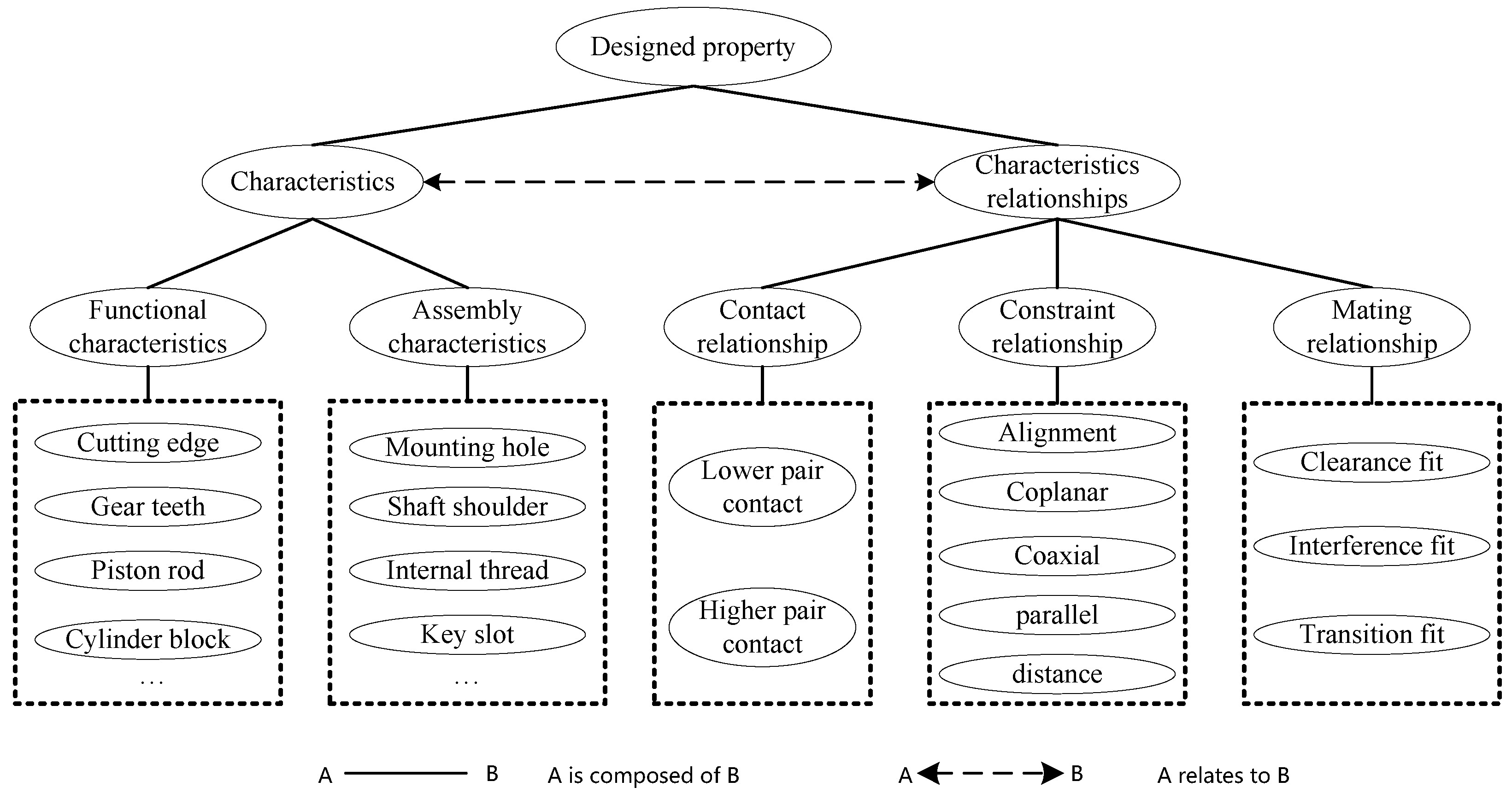
Designed properties refer to the designed characteristics of the base material of the designed object, also known as its geometric features, including functional features and assembly features, as shown in
Figure 2. A functional feature refers to a feature by which the designed object directly interacts with the acting object, such as the cutting-edge feature of the drill bit, the gear tooth feature, etc.; the assembly feature refers to the actual feature by which the designed object associates with other objects in the system, such as hole features, thread features, groove features, etc. These assembly features include three characteristic relationships, namely, contact relationships, constraint relationships, and mating relationships. Specifically, contact relationships include both low-pair contact relationships and high-pair contact relationships. Constraint relationships include alignment relationships, coplanar relationships, coaxial relationships, parallel relationships, distance relationships, etc. Matching relationships include clearance-fit relationships, interference fit relationships, and transition fit relationships. The designed properties are the main design objects in the design process. The designer needs to create a suitable geometric shape for the selected base material, according to the relevant technical principles. For example, it is possible to determine the main tooth-profile characteristic parameters of a gear according to the gear design principle (such as the number of teeth, modulus, tooth width, standard pitch diameter, etc.).
Environmental properties refer to the properties that are naturally given by the environment when the designed object is in the corresponding external environment, such as ambient temperature, humidity, air pressure, and gravity. Some of the inherent properties or designed properties of the designed object may interact with the environmental properties. Since the designed object ultimately has a specific application environment, environmental properties can be regarded as elements of the working conditions that the designed object needs to face. This presents a good supplement to considering environmental properties in the conceptual design process.
Some inherent properties of the designed object may not be stable and will be more susceptible to environmental properties. For instance, the temperature of the environment may affect the ductility of the metal and the solubility of salt in water. Therefore, the inherent properties that can produce changes under the action of environmental properties are called influential properties. Influential properties are often the key objects by which the designed object can play a role. Therefore, the influential properties that are used to achieve the expected purpose are referred to as functional properties. For example, the thermal expansion of metal sheets will change with the ambient temperature. As the temperature increases, the expected deformation of the metal sheet will be generated as a corresponding displacement in the specified direction, acting to control the switch of the circuit. This thermal expansion is the physical property of the metal sheet, and it can be affected by the environmental property. The property (temperature) produces a certain change, and this change is used to achieve the desired purpose. Therefore, thermal expansion is regarded as a functional property of the metal sheet.
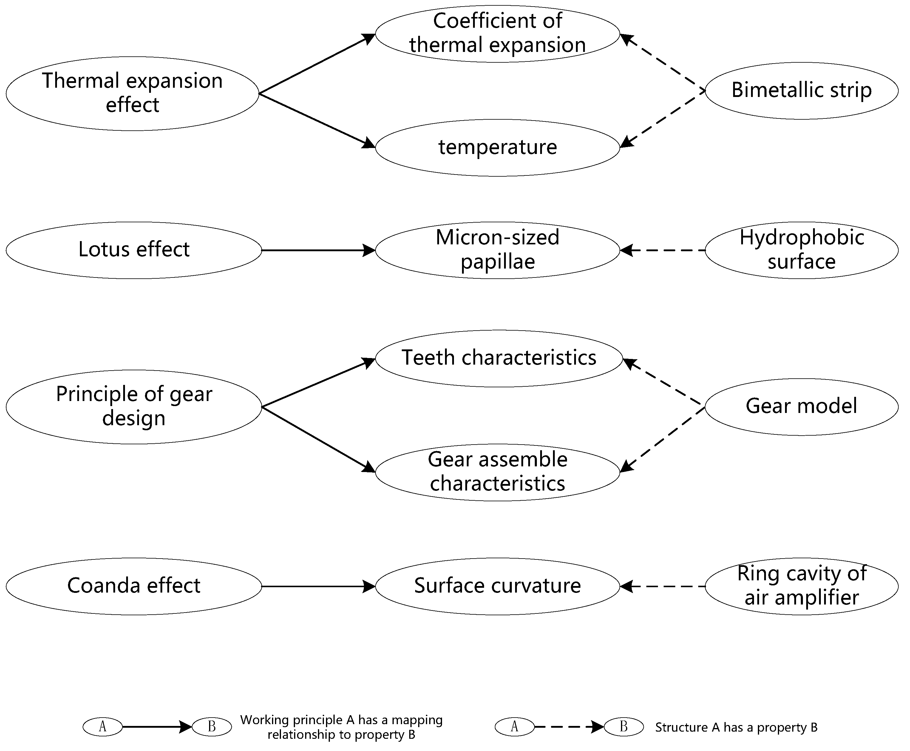
The mapping model between the working principle and the property is shown in
Figure 3, and several specific mapping examples are presented in
Figure 4.
3.3. Property Relationship
The reason why a cutting tool used in machining can be employed to remove material from the machined object is that there is an obvious difference in hardness between the cutting edge of the cutting tool and the machined object. In this case, the realization of function (remove + material) is mainly related to the different values of a common property (hardness). The property and the property relationship are vital to realizing a function. The property relationship describes how two design objects interact with each other. For property i of object A and property j of object B, the relationship between property i and property j can help to realize the goal function. For example, the external thread of the screw and the internal thread of the screw hole can only screw together to realize their connection function when the characteristic parameters of the external thread and the internal thread are the same.
In the following section, this paper will discuss the property relationship between inherent properties and designed properties.
The property relationship of an inherent property includes the comparison relation (CR) and existence relation (ER). The former indicates that the value of the same inherent property of two design objects can be compared numerically; the latter indicates whether two design objects have a certain common property.
CR can be described as a triple:. It includes the inherent property i of design object A (), the same inherent property i of design object B (), and a comparison operator. The comparison operator has three forms (>, <, and =).
ER is a binary group and can be described as: . The existence of is described by , where 1 represents the fact that design object A has property i, while 0 indicates that design object A does not have property i.
The property relationship of designed properties includes the geometric dimension constraint relationship (GDCR) and the spatial position constraint relationship (SPCR). GDCR indicates that there should be an appropriate geometric dimension relationship between directly related designed properties, such as the dimensional constraint relationship between the key and keyhole. GDCR aims to ensure the assembly rationality between design objects. SPCR refers to the appropriate relative spatial position relationship between two directly related designed properties, such as the coaxial constraint relationship between the hole and the axis. SPCR aims to limit the spatial degree of freedom of the design object, to ensure that the object has definite action opportunities. Once the relative spatial position relationship between two directly related design objects is effectively limited (i.e., the spatial degree of freedom of the design object is limited), the action object will naturally produce the expected execution action, given the input variable.
GDCR can be described as a triple: . It includes the associated parameter of the designed property , a comparison operator, and the associated parameter of the designed property . The comparison operator has three forms (>, <, and =).
SPCR can also be described as a triple: . This includes the associated feature of the designed property , the associated parameter of the designed property , and a position relation element, . is used to describe the spatial position of two associated features. It incorporates coaxial, coincident, parallel, collinear, aligned, linear, angular distance, etc.
The purpose of design is to find or create a group of components with specific associations to meet the design requirements and the user’s needs. In terms of FBS, researchers basically reach a consensus on the definition of structure, i.e., “Structure is the component or element of artificial objects and the relationship between them”. In addition to this approach, there are several other understandings of the definition of structure. The structure of an object is the union of the object and the relations on the object (Zeng Yong, 2002) [
35]. Artificial devices enable the transformation of artifacts to carry functional and physical information in a structured manner (Mckay, A., et al., 2016) [
36]. Based on the above definition, Chen Yong et al. (2015) [
23,
24] introduced the auxiliary environment elements of the product system, proposed the triple definition of the structure, and put forward the argument that the structure of the product system should include the components of the product system, the auxiliary environment of the product system, and the correlation between all objects in the product system. For example, in addition to the washing machine itself, the washing machine system also needs to include auxiliary environmental objects, such as water, detergent, and electricity. This type of definition highlights the constituent elements of the product system from the super system wherein the product is located. However, this paper focuses on the design objects involved in the design process, especially the conceptual design process, and mainly focuses on the constituent elements of the product system. Considering this, the structural concepts are presented as follows.
3.4. Structure (S)
From the three perspectives of the materiality, functionality, and relevance of the design object, the structure is understood as material composition (MC), technical characteristics (), and affiliation (Af), i.e., Material composition refers to what a structure is made of, which determines the inherent property elements of the design object. For example, the material composition of a gear refers to the base material used for manufacturing the gear, such as medium carbon steel. Technical characteristics refer to the appearance characteristics that are artificially given to the structure to realize the desired function, based on material composition. Technical characteristics directly constitute the designed properties of a structure. For example, the technical characteristics of a gear include the gear tooth characteristics, mounting hole characteristics, keyway characteristics, etc. Affiliation refers to the external relationships between structures, which mainly involve assembly relations. Meanwhile, this association refers to the assembly relationship of certain technical characteristics of a structure. For example, the affiliation of the gear includes the assembly relationship between the gear and the shaft. Furthermore, it includes the assembly relationship between the mounting hole feature of the gear and the support shoulder feature of the shaft.
If the product system is separated from the perspective of parts and components, the structure in the product system can be roughly divided into two categories: the part structure and the component structure. The part structure includes the material composition, technical features, and affiliation. The component structure includes the part structures constituting the component, the correlations between the part structures, and the correlations between the component and other components. For example, the component structure–reducer structure includes the shell, bearing, shaft, gear, and other structures, along with the correlation between these structures, such as the assembly relationship between the shaft and bearing, gear and shaft, and the input shaft and the external structure, etc. The relationship between structures, whether a part structure or a component structure, is mainly manifested in the assembly relationship between the structures and the action–trigger relationship between the structures. The part structure–gear structure relationship includes the characteristic parameters of the gear, the connection relationship between the gear and shaft, the meshing relationship between the gear and its corresponding gear, etc.
Based on the above analysis of the structure concept, referring to the description of the matter–element relationship in extenics (Li, W.J., et al., 2018) [
37], the structural element (Se) and relationship element (Re) are expressed as follows:
In the structure element,
is the abbreviation of the structure name, and relationship element is chosen to establish the relationship between this structure element and other structure elements. A relation element can be described by a quintuple of five elements, including the relation element number (
), relation type (
), specific relation (
), associated
, and associated
:
4. The Extended Functional Design Approach
In this section, the extended functional design approach is proposed, as shown in
Figure 5, which follows some representations of the FBS model [
4,
7]. Generally, the approach includes five processes (1–5) and integrates two design strategies. Specifically, strategy 1 is represented by process 1 (from function to structure), which could be realized via most of the existing functional design approaches discussed in
Section 2. Meanwhile, strategy 2 is represented by processes 2, 3, and 4 (if necessary, one can also include process 5), which is characterized by the integration of the working principle and the property to realize the transformation from the desired function to the possible structure.
Process 1—Design reuse process, from function to structure (F–S):
This is a recalling and reusing process to find a structure solution to the desired function by function-oriented searching, a structure analogy, a bio-inspired analogy, etc. This process could be completed using most of the existing functional design approaches discussed in
Section 2. Therefore, it will not be described in detail in this paper.
Process 2—Mapping process, from function to working principle (F–WP):
This is a divergent process to find the available working principles for the desired function. Some functions cannot be realized by direct design reuse or adaptation, which makes it necessary to consider how to generate a new structure solution, based on a working principle. There may be a one-to-many mapping relationship between a function and the working principles, and several working principles that have the possibility to achieve the desired goal may be found. For example, the function “change position” may correspond to working principles, including “thermal expansion and contraction”, “Hooke’s law”, “hydraulic transmission”, “pneumatic transmission”, “electromagnetic effect”, etc. For each trial, only one working principle should be selected as a step into the next process. If the selected working principle does not result in a satisfactory structure, then the designers can return to this process and select a different candidate working principle.
Process 3—Analysis process, from working principle to property (WP–P):
This is an analytical process to derive the appropriate properties, according to the selected working principle in Process 2. The working principle only has a chance to realize the desired function when it is applied to the correct property. For example, the thermal expansion and contraction principle is closely related to the thermal expansion property, which can be quantified by the thermal expansion coefficient. The larger the value of the coefficient, the more sensitive the material is to a temperature rise, and the more obvious the volume expansion. The working principle of a bimetallic strip in a common bimetal thermostat is the thermal expansion and contraction principle; metal sheets with different thermal expansion coefficients are deformed and displaced to connect or disconnect the circuit, thereby controlling the circuit.
Process 4—Synthesis process, from property to structure (P–S):
This is a synthesis process. After identifying the property, it is necessary to consider how to integrate this property into a complete structure. The identified property is necessary for realizing the desired function; a complete structure must have some other auxiliary properties. Referring to the bimetal mentioned above, in addition to its thermal expansion property, designers must consider other properties that are also needed.
Process 5—Reformulation process, from structure to working principle (S–WP):
This is an iterative process. Because Process 2 is a divergent process, there may be many available working principles for a function, and only one candidate working principle can be selected at a time. If the selected working principle does not lead to a good structure, the designers could return to Process 2 and select other candidate working principles, continuing until a feasible structure is generated.
The extended functional design approach provides a new way of thinking about the transformation from function to structure, which has no conflict with the existing functional design approach. For a design task, when the function tree is finished, it is available for designers to choose a strategy to realize one function. The proposed approach aims to generate a feasible structure for the desired function, based on the working principle and property. It provides another choice for designers if they cannot obtain suitable design solutions from the existing approaches. Some closely related issues in functional design, i.e., the transformation from customer to function, function decomposition, the coupling and decoupling issues between functions, etc., are not considered in this work; they will be investigated in future research.
Additionally, when compared with the FBS model of John S. Gero (1990) [
4,
7], one of the most obvious differences is that the ‘
Formulation (F to Be)’ and the ‘
Evaluation (between Be and Bs)’ are not involved in
Figure 5. In the proposed functional design approach, there is no expected behavior
(Be) or actual behavior
(Bs) in the transformation process from function to structure. When reasonable working principles are selected and the corresponding properties are identified, the so-called behavior of a structure will be determined accordingly. Therefore, a one-way transformation process (
F to WP to P to S) is proposed, and a reformulation process from S to WP is regarded as the start of an iterative design process if a good structure could not be generated from the former working principle. Meanwhile, there is no direct conflict between the FBS model and the proposed model. The goal of this proposed model is to provide a new understanding of the transformation from function to structure by employing the working principle and property as immediate transformation variables. They do not challenge the role of behavior in the FBS model; instead, they provide a supplementary explanation of that behavior.
Figure 6 illustrates the analytical process in the functional domain, the synthesis process in the structural domain, and the mapping relationships between functions and structures. This is an improvement to the zigzag mapping model [
6]. The function–structure mapping step is divided into direct mapping and indirect mapping. Direct mapping refers to Strategy 1, by which the existing structures can be directly retrieved through a function without any major modifications. Indirect mapping refers to Strategy 2, which needs to undergo the transformation process of function–working principle–property–structure, to generate new and appropriate structures. In conceptual design, the two mapping relationships are complementary.
5. Case Study
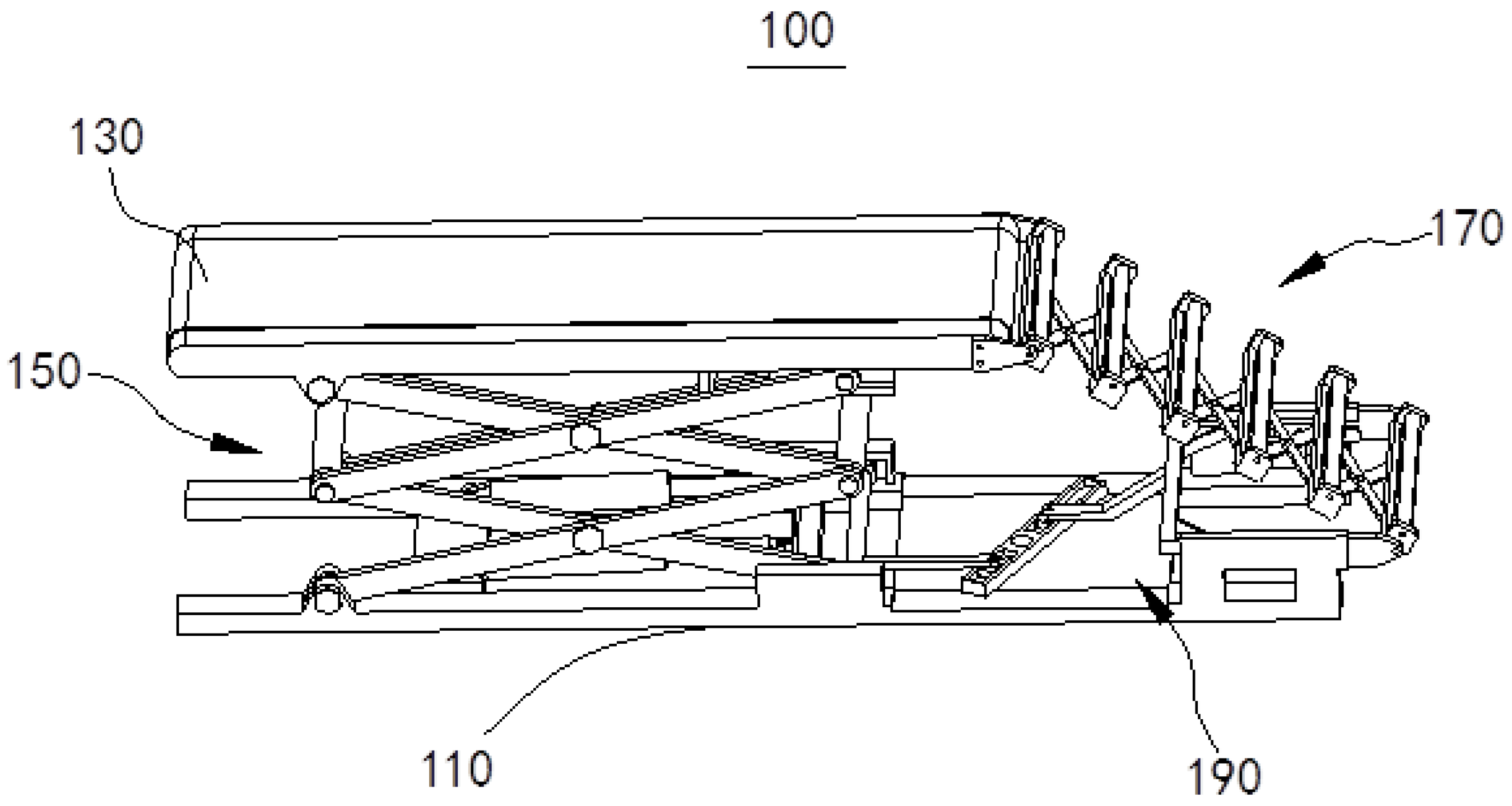
In this section, the conceptual design of a self-adaptive luggage transfer device will be taken as an example and discussed using the method proposed above. The conceptual design solution is shown in
Figure 7, and has already been granted a Chinese invention patent (No. ZL 201910830749.1) and a United States invention patent (No. US 10968047B2). Generally, passengers’ luggage needs to be manually transferred to travel centers, such as airports or ports. For example, after the arrival of flights, the passengers’ luggage is stacked on luggage cars; at this time, ground service staff need to carry the stacked luggage one by one from the top of the stack to the ground conveyor belt. The transfer process involves strong working intensity and high labor costs.
(In the model shown inFigure 7: 100, the self-adaptive luggage transfer device; 110, the base; 130, the conveyor mechanism; 150, the lifting mechanism; 170, the self-adaptive extendable transfer mechanism; 190, the reverse displacement amplification mechanism).
According to the above consideration, in this conceptual design task, the overall function is to transfer luggage from one place to another, and two primary functions are clarified. First, the designed device should relocate the luggage to the designated position, which process comprises horizontal transfer and inclined transfer. Second, the expected device could adjust the horizontal height of the conveyor mechanism to accommodate the luggage being located at different heights.
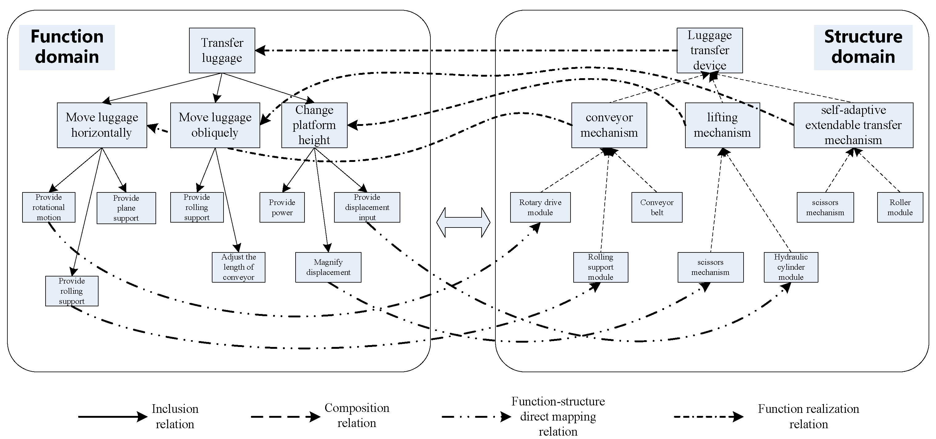
Figure 8 shows the simplified function–structure mapping relation of this self-adaptive luggage transfer device. In the left function domain, the total function “transfer luggage” is decomposed into a three-layer function tree. Function modules are located in the middle level, while function units are located in the bottom level. In the right structure domain, specific structure units are mapped to the function units; they are directly generated according to the function units. The structure modules in the middle level are composed of specific structure units. In the middle level, the function modules are realized by structure modules. In the concept generation stage, designers focus on the bottom level—how to generate an available structure unit according to an expected function unit.
In this case, the conceptual solutions to the lifting mechanism (150) are chosen to explain the proposed approach, based on Strategy 2 (Processes 2, 3 to 4).
The Conceptual Design of the Lifting Mechanism
When considering the function of the lifting mechanism, it is expected to flexibly raise and lower the height of the conveyor mechanism (130). The realization of this function should be dependent on a principle that allows a reciprocating displacement change.
Process 2 (F–WP): To realize a reciprocating displacement change, several available working principles could be considered; i.e., the principle of hydraulic transmission, the principle of thermal expansion and contraction, the principle of variable triangles, etc. The principle of hydraulic transmission will directly map onto a hydraulic cylinder device. In a real working space, if a multi-stage hydraulic cylinder is used, it may cause the hydraulic cylinder piston to travel too far and may also lead to a complex structure. Regarding the principles of thermal expansion and contraction, it will not be able to bear the actual workload. Therefore, the above two principles are not selected. Regarding the principle of variable triangles, this could ensure the stability of the structure and provide variable displacement. In addition, the structure’s input displacement and output displacement are not in the same direction, which helps to reduce the volume of the structure. Hence, the variable triangles principle can be selected as a candidate working principle to progress to the next design process.
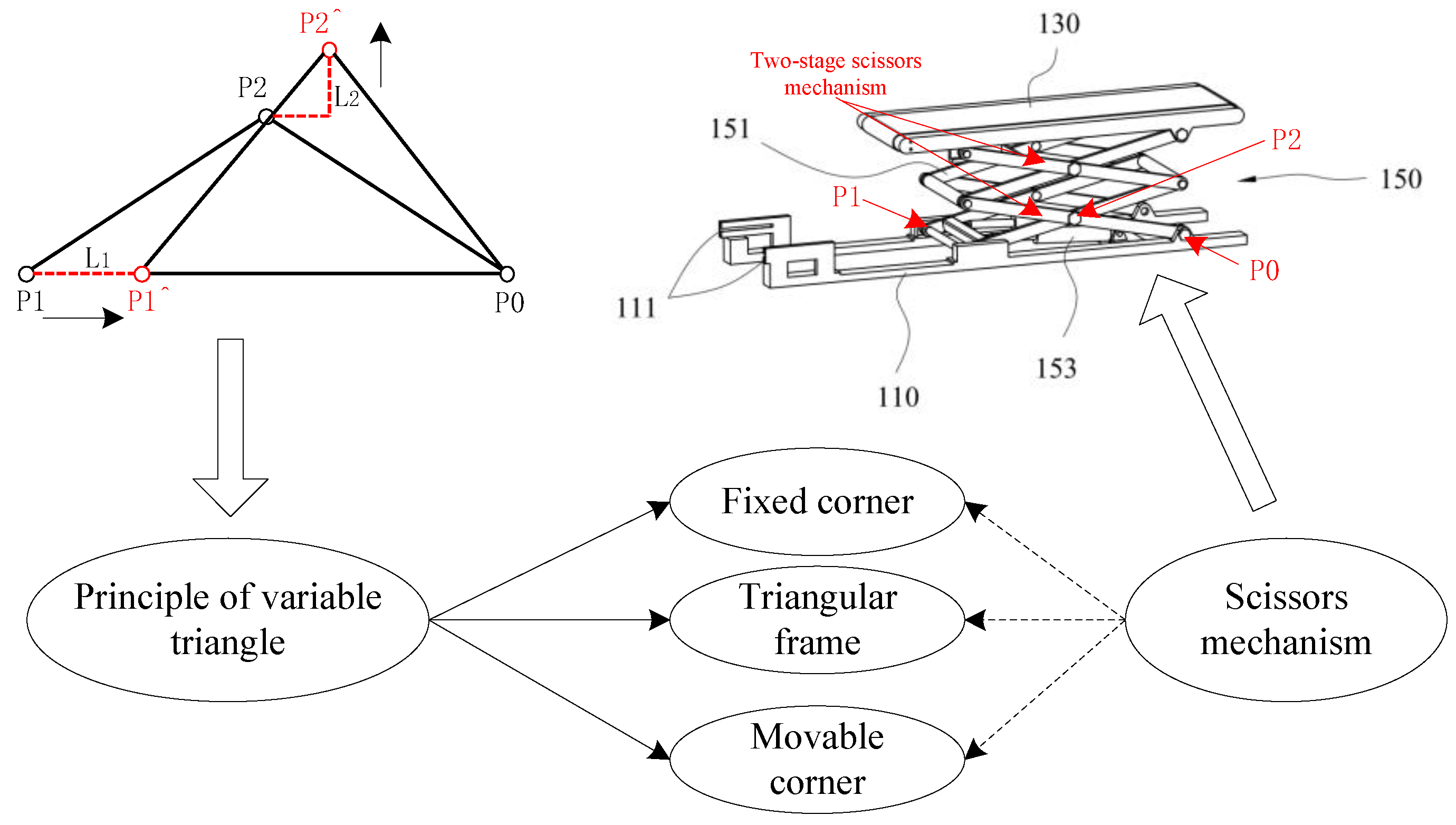
Process 3 (WP–P): As shown in the schematic diagram in the upper left-hand corner of
Figure 9, the principle of variable triangles requires a fixed corner (P0), an active moving corner (P1), and a passive moving corner (P2), to form two fixed-length edges (P2P1 and P2P0) and one variable-length edge (P0P1), creating an isosceles triangle. The active moving corner is taken as the displacement input and the passive moving corner is taken as the displacement output, which realizes the need for switching from horizontal displacement (L1) to vertical displacement (L2). According to these key properties, the corresponding structure will be generated in the next design process.
Process 4 (P–S): After the key properties in the principle of variable triangles are identified, the actual structure is generated, as shown in the upper right-hand corner of
Figure 9. To improve the device’s lifting height range, a multi-stage variable triangle structure is designed, which is called the scissors mechanism.


