
Optimal Path Configuration with Coded Laser Pilots for Charging Electric Vehicles Using High Intensity Laser Power Beams


Abstract
:1. Introduction
- A power reception model of the PRX using coded laser pilot is proposed and validated through extensive simulations.
- A novel model is proposed for selecting appropriate transmitters from several PTXs, where the PRX uses various wireless power channels (WPC) and coded laser pilots. The proposed algorithm enables developing a simple system because it does not require the PTX to perform a series of processes for positioning the PRX.
- The performance of three different schemes for WPC is analyzed with the proposed algorithm, including PTX selection using the highest PTE first, the least PTE first, and PTX selection based on the best PTE first.
- The photovoltaic (PV) model is validated through simulations and experiments while the path configuration model through simulations using a multi-channel WTP system comprising several PRXs and several PTXs that employ a coded laser pilot and received channel power indicator (RCPI)-based selection system.
2. Background and Related Work
3. Received Power Model of a PV Array with Experimental Validation
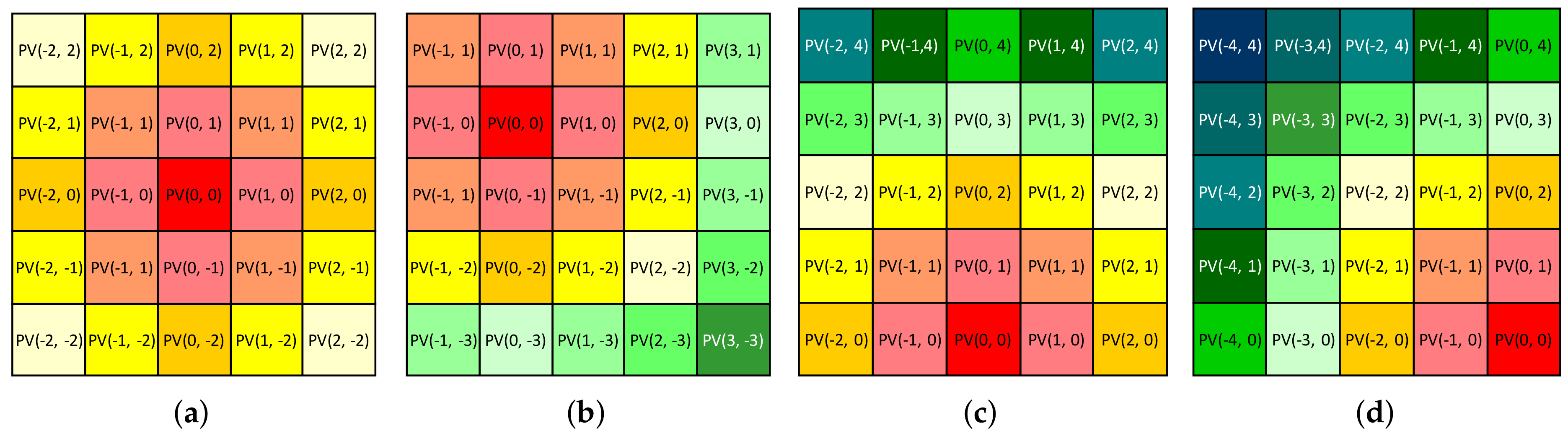
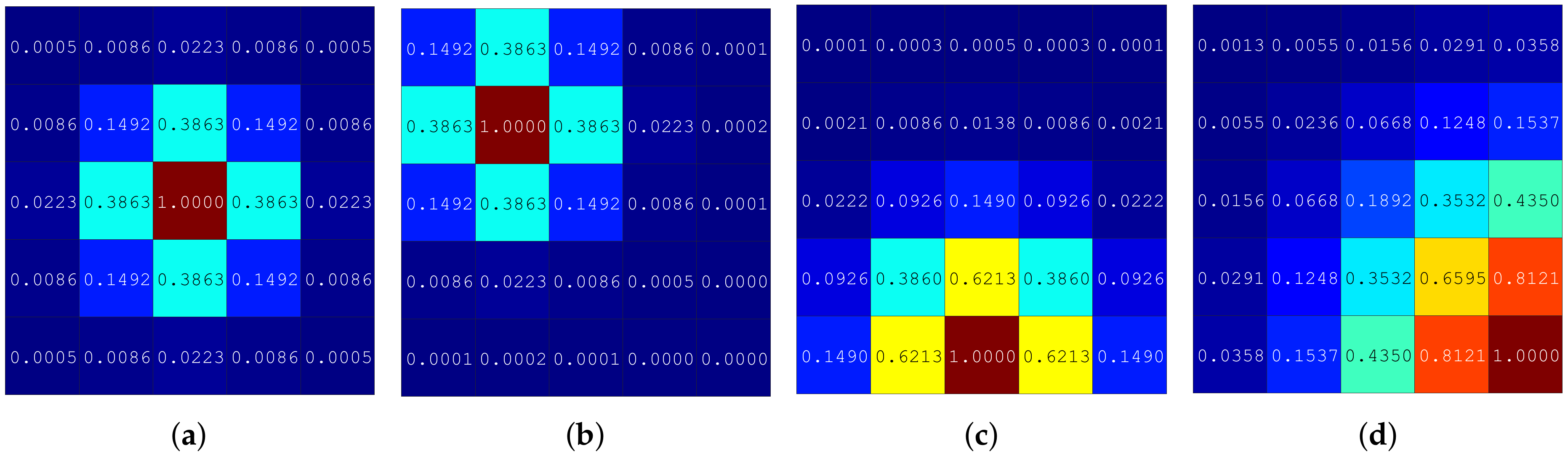
3.1. Modeling of Received Power at PV Array
- : diameter of the transmitted laser beam ();
- : divergence angle of the transmitted laser beam ();
- : distance between PTX and PRX ();
- : incident angle of the laser beam on the PV array (°).
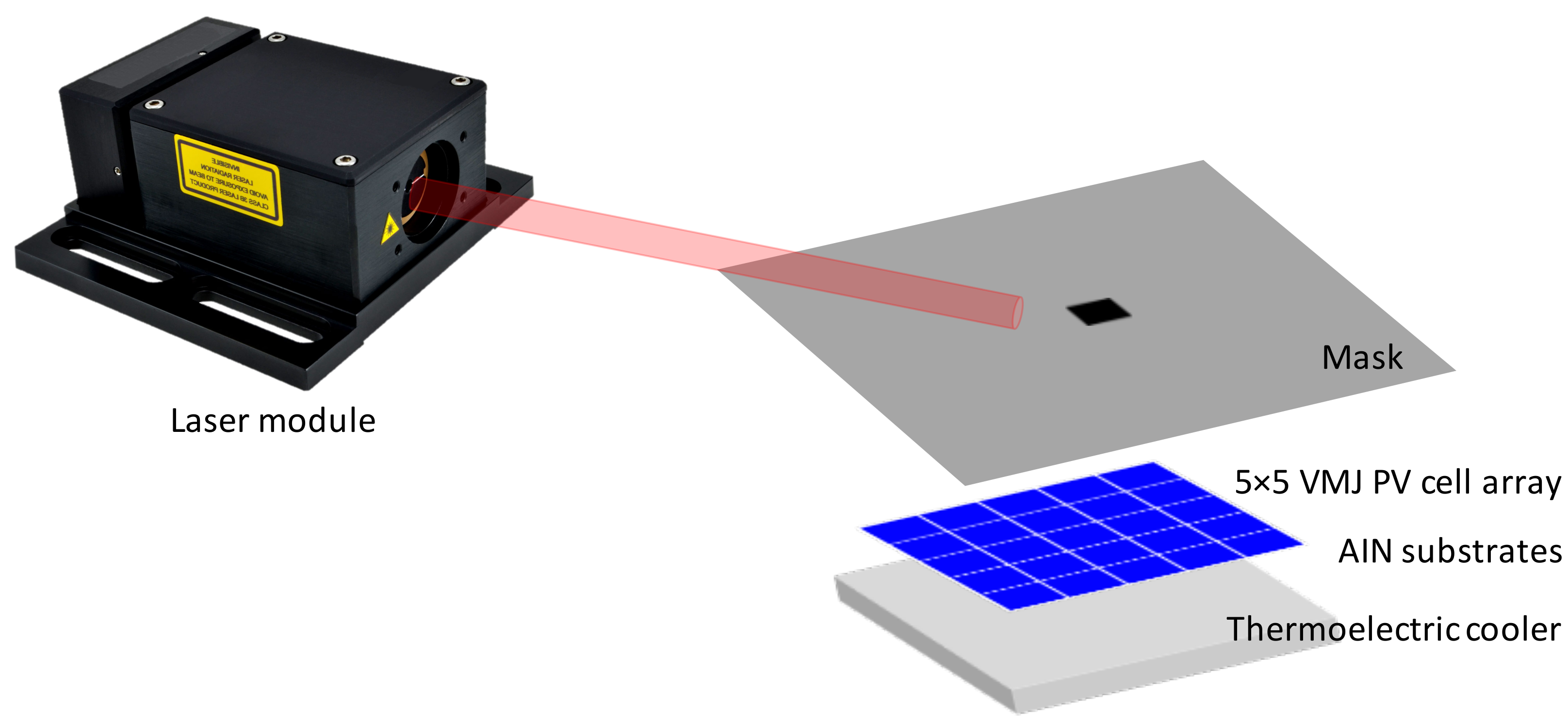
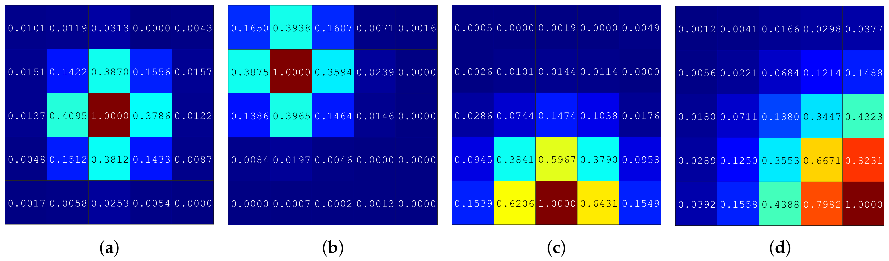
3.2. Experimental Validation of Received Power Model
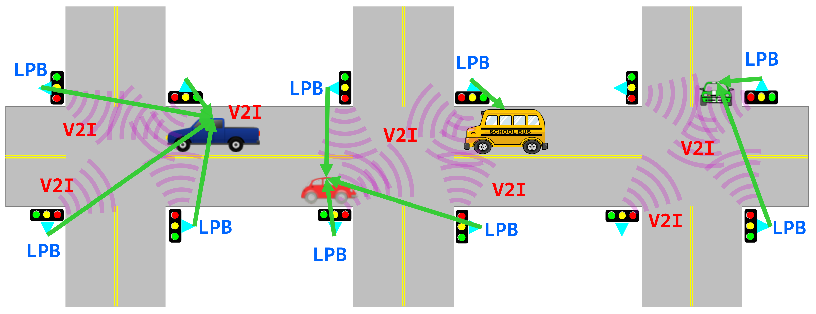
4. Structure and Operation of Coded Laser Pilots-Based HILPB WPT System
4.1. Power Transmitter (PTX)
| Algorithm 1 PTX operation algorithm. |
|
4.2. Power Receiver (PRX)
| Algorithm 2 PRX operation algorithm. |
|
5. Simulation of Coded Laser Pilots-Based HILPB WPT System
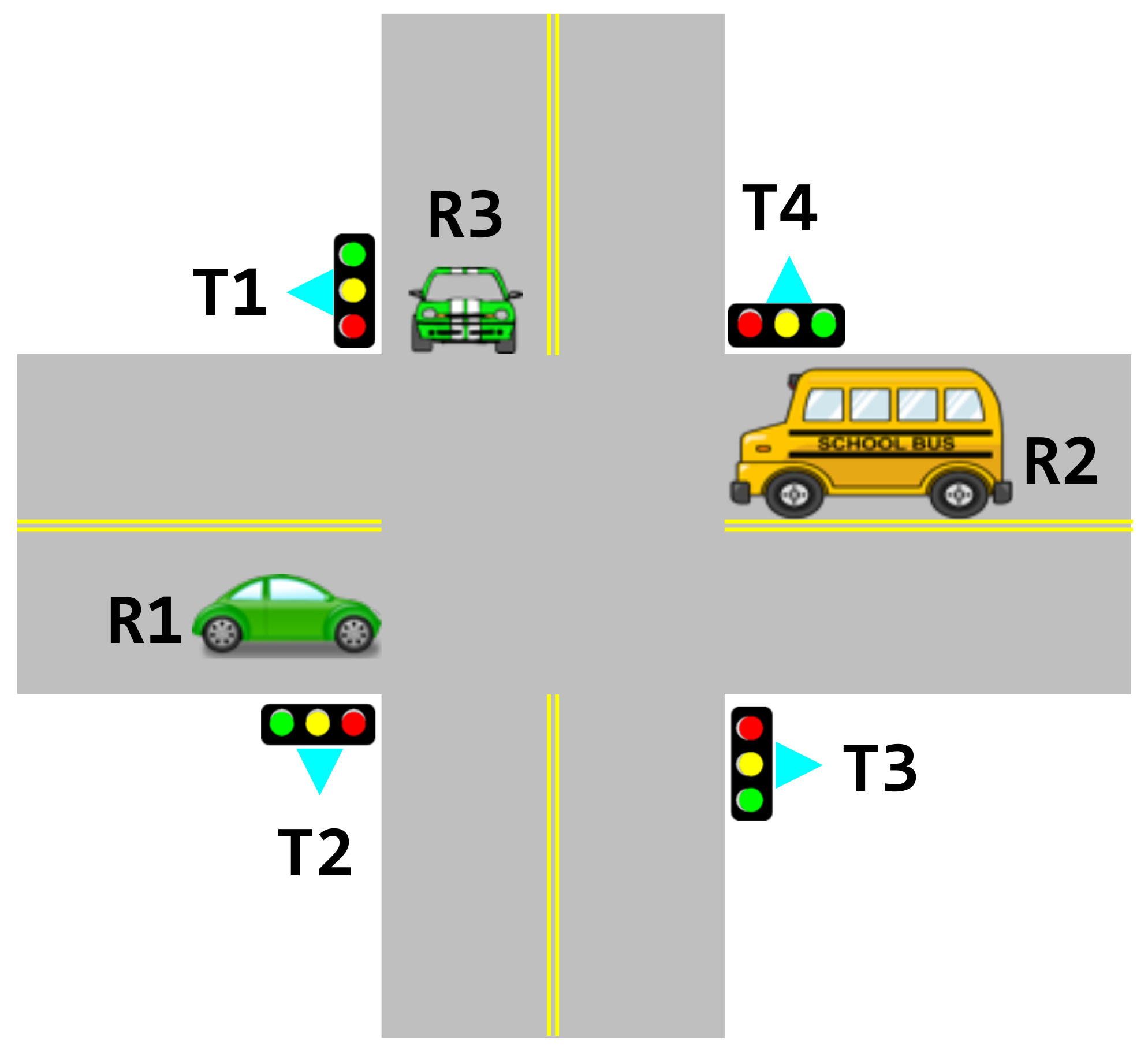
5.1. Simulation Environment
5.2. Simulation Results
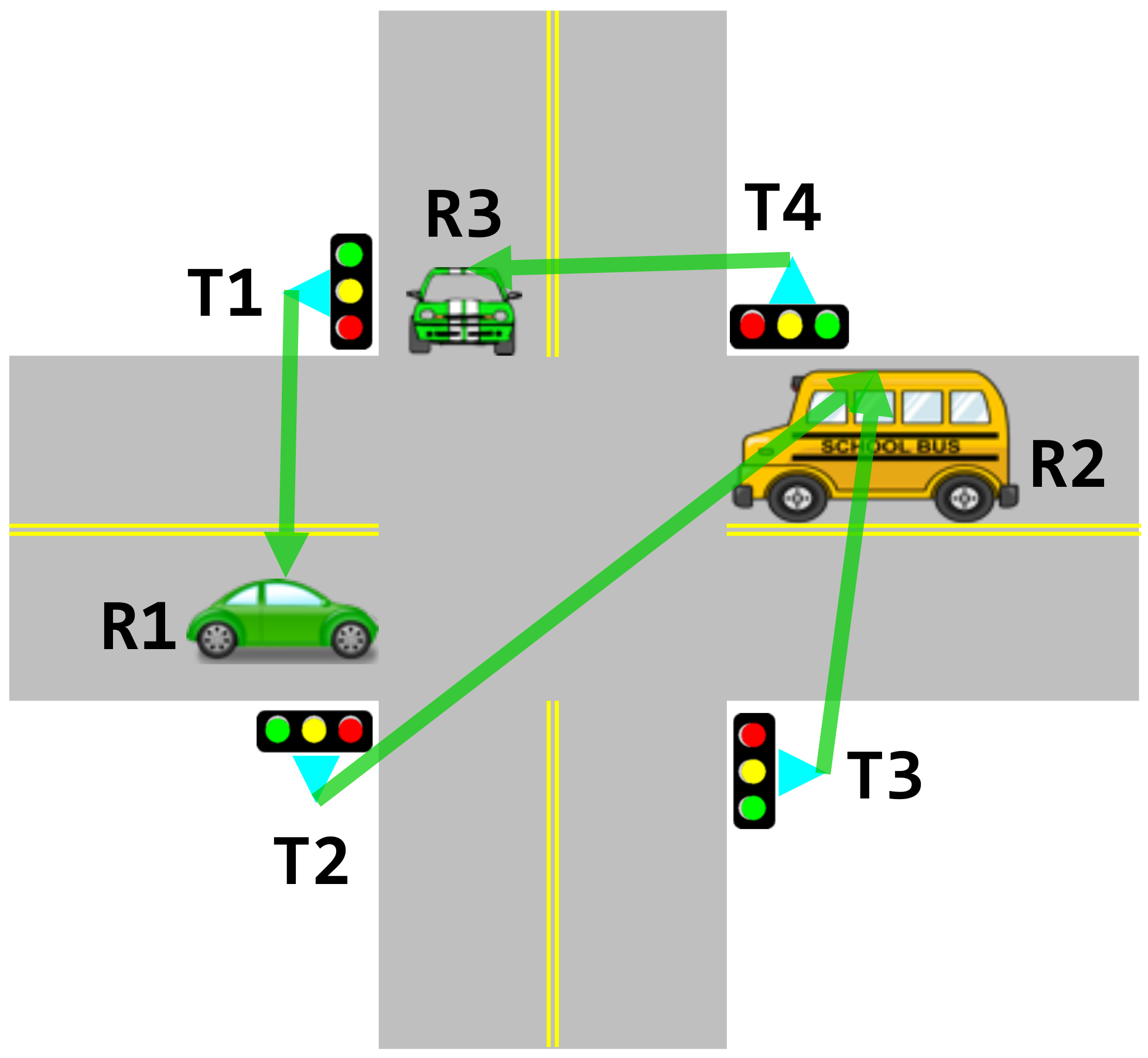
5.2.1. Pairing Algorithm Based on Maximum Receivable Power

| PRX-PTX Pairing Sequences | ||||
|---|---|---|---|---|
| First Round | Second Round | Third Round | ||
| PRX | R1 | 289.8 kW, 200 kW | 289.8 kW, 200 kW | 289.8 kW, 200 kW |
| R2 | - | 433.65 kW, 300 kW | 433.65 kW, 300 kW | |
| R3 | - | - | 129.9 kW, 150 kW | |
| PTX | T1 | (162, 189), 300 kW | (162, 189), 300 kW | (162, 189), 300 kW |
| T2 | - | (173, 333), 250 kW | (173, 333), 250 kW | |
| T3 | - | (154, 283), 200 kW | (154, 283), 200 kW | |
| T4 | - | - | (150, 236), 150 kW | |

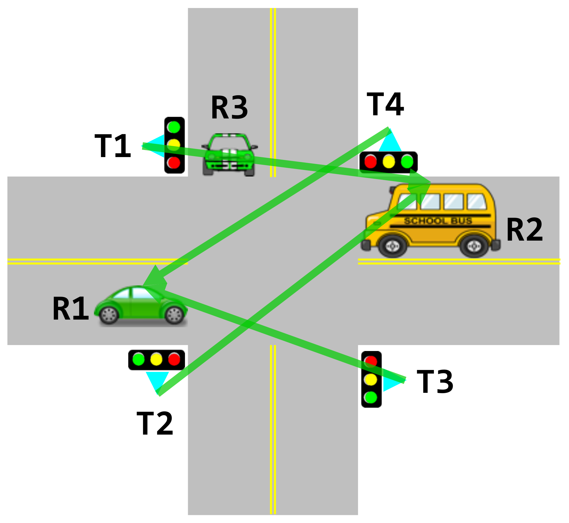
5.2.2. Pairing Algorithm Based on Least Receivable Power
| PRX-PTX Pairing Sequences | ||||
|---|---|---|---|---|
| First Round | Second Round | Third Round | ||
| PRX | R1 | 315.3 kW, 200 kW | 315.3 kW, 200 kW | 315.3 kW, 200 kW |
| R2 | - | 492.8 kW, 300 kW | 492.8 kW, 300 kW | |
| R3 | - | - | 0 kW, 150 kW | |
| PTX | T1 | - | (153, 103), 300 kW | (153, 103), 300 kW |
| T2 | - | (149, 56), 250 kW | (149, 56), 250 kW | |
| T3 | (161, 283), 200 kW | (161, 283), 200 kW | (161, 283), 200 kW | |
| T4 | (173, 153), 150 kW | (173, 153), 150 kW | (173, 153), 150 kW | |

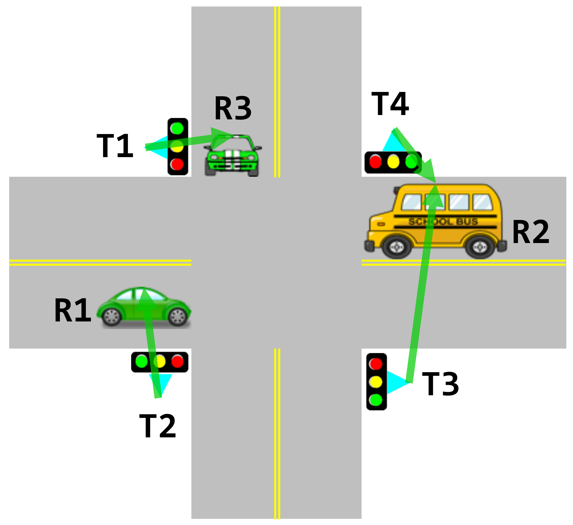
5.2.3. Pairing Algorithm Based on the Best PTE Power
| PRX-PTX Pairing Sequences | ||||
|---|---|---|---|---|
| First Round | Second Round | Third Round | ||
| PRX | R1 | 231.75 kW, 200 kW | 231.75 kW, 200 kW | 231.75 kW, 200 kW |
| R2 | - | 318.1 kW, 300 kW | 318.1 kW, 300 kW | |
| R3 | - | - | 297.9 kW, 150 kW | |
| PTX | T1 | - | - | (173, 63), 300 kW |
| T2 | (154, 13), 250 kW | (154, 13), 250 kW | (154, 13), 250 kW | |
| T3 | - | (150, 326), 200 kW | (150, 326), 200 kW | |
| T4 | - | (162, 279), 150 kW | (162, 279), 150 kW | |

6. Conclusions
Author Contributions
Funding
Institutional Review Board Statement
Informed Consent Statement
Data Availability Statement
Conflicts of Interest
Abbreviations
| AlN | Aluminum nitride |
| ANSI | American National Standard Institute |
| COTS | Commercial off the shelf |
| DS-OCDMA | Direct-sequence optical code division multiple access |
| EV | Electric vehicle |
| HILPB | High-intensity laser power beaming |
| MPQ | Maximum power requirement |
| MTP | Maximum transmission power |
| PCI | Power channel information |
| PPC | Photovoltaic power conversion |
| PRXs | Power receivers |
| PTE | Power transfer efficiency |
| PTXs | Power transmitters |
| PV | Photovoltaic |
| RCPI | Received channel power indicator |
| TCO | Total cost of ownership |
| TEC | Thermoelectric cooler |
| V2I | Vehicle-to-infrastructure |
| VMJ | Vertical multi-junction |
| WPC | Wireless power channel |
| WPT | Wireless power transmission |
References
- China, M. China Vehicle Environmental Management Annual Report 2016; Ministry of Ecology and Environment of the People’s Republic of China: Beijing, China, 2016. [Google Scholar]
- Ashfaq, M.; Butt, O.; Selvaraj, J.; Rahim, N. Assessment of electric vehicle charging infrastructure and its impact on the electric grid: A review. Int. J. Green Energy 2021, 18, 1–30. [Google Scholar] [CrossRef]
- El-Bayeh, C.Z.; Alzaareer, K.; Aldaoudeyeh, A.M.I.; Brahmi, B.; Zellagui, M. Charging and Discharging Strategies of Electric Vehicles: A Survey. World Electr. Veh. J. 2021, 12, 11. [Google Scholar] [CrossRef]
- Li, S.; Mi, C.C. Wireless Power Transfer for Electric Vehicle Applications. IEEE J. Emerg. Sel. Top. Proc. 2015, 3, 4–17. [Google Scholar] [CrossRef]
- Baronti, F.; Chow, M.Y.; Ma, C.; Rahimi-Eichi, H.; Saletti, R. E-transportation: The Role of Embedded Systems in Electric Energy Transfer from Grid to Vehicle. EURASIP J. Embed. Syst. 2016, 2016, 11. [Google Scholar] [CrossRef]
- Bi, Z.; Kan, T.; Mi, C.C.; Zhang, Y.; Zhao, Z.; Keoleian, G.A. A Review of Wireless Power Transfer for Electric Vehicles: Prospects to Enhance Sustainable Mobility. Appl. Energy 2016, 179, 413–425. [Google Scholar] [CrossRef] [Green Version]
- Shadid, R.; Noghanian, S.; Nejadpak, A. A literature survey of wireless power transfer. In Proceedings of the 2016 IEEE International Conference on Electro Information Technology (EIT), Grand Forks, ND, USA, 19–21 May 2016; pp. 0782–0787. [Google Scholar]
- Di Capua, G.; Sánchez, J.A.; Cabrera, A.T.; Cabrera, D.F.; Femia, N.; Petrone, G.; Spagnuolo, G. A losses-based analysis for electric vehicle wireless chargers. In Proceedings of the 2015 International Conference on Synthesis Modeling, Analysis and Simulation Methods and Applications to Circuit Design (SMACD), Istanbul, Turkey, 7–9 September 2015; pp. 1–4. [Google Scholar]
- Summerer, L.; Purcell, O. Concepts for Wireless Energy Transmission via Laser; Report; Europeans Space Agency (ESA)-Advanced Concepts Team: Noordwijk, The Netherlands, 2009. [Google Scholar]
- Nugent, T.J., Jr.; Kare, J.T. Laser Power Beaming for Defense and Security Applications. Int. Soc. Opt. Photonics 2011, 8045, 804514. [Google Scholar] [CrossRef]
- Bhatti, A.R.; Salam, Z.; Aziz, M.J.B.A.; Yee, K.P. A Critical Review of Electric Vehicle Charging using Solar Photovoltaic. Int. J. Energy Res. 2016, 40, 439–461. [Google Scholar] [CrossRef]
- Sprangle, P.; Hafizi, B.; Ting, A.; Fischer, R. High–Power Lasers for Directed–Energy Applications. Appl. Opt. 2015, 54, F201–F209. [Google Scholar] [CrossRef] [PubMed]
- Triviño-Cabrera, A.; González-González, J.M.; Aguado, J.A. Compensation Networks. In Wireless Power Transfer for Electric Vehicles: Foundations and Design Approach; Springer: Berlin/Heidelberg, Germany, 2020; pp. 69–100. [Google Scholar]
- Hutchinson, L.; Waterson, B.; Anvari, B.; Naberezhnykh, D. Potential of wireless power transfer for dynamic charging of electric vehicles. IET Intell. Transp. Syst. 2018, 13, 3–12. [Google Scholar] [CrossRef] [Green Version]
- Tran, D.H.; Choi, W. Design of a high-efficiency wireless power transfer system with intermediate coils for the on-board chargers of electric vehicles. IEEE Trans. Power Electron. 2017, 33, 175–187. [Google Scholar] [CrossRef]
- O’Neill, M.J.; Piszczor, M.F.; Eskenazi, M.I.; McDanal, A.J.; George, P.J.; Botke, M.M.; Brandhorst, H.W.; Edwards, D.L.; Hoppe, D.T. Ultralight Stretched Fresnel Lens Solar Concentrator for Space Power Applications. Int. Soc. Opt. Photonics 2003, 5179, 116–126. [Google Scholar] [CrossRef]
- Osepchuk, J.M. Microwave Policy Issues for Solar Space Power. Space Policy 2000, 16, 111–115. [Google Scholar] [CrossRef]
- Christ, A.; Douglas, M.; Nadakuduti, J.; Kuster, N. Assessing Human Exposure to Electromagnetic Fields from Wireless Power Transmission Systems. Proc. IEEE 2013, 101, 1482–1493. [Google Scholar] [CrossRef]
- Jiang, H.; Brazis, P.; Tabaddor, M.; Bablo, J. Safety Considerations of Wireless Charger for Electric Vehicles–A review paper. In Proceedings of the 2012 IEEE Symposium on Product Compliance Engineering (ISPCE), Portland, OR, USA, 5–7 November 2012; pp. 1–6. [Google Scholar] [CrossRef]
- Dickinson, R.M. Safety issues in SPS wireless power transmission. Space Policy 2000, 16, 117–122. [Google Scholar] [CrossRef]
- Duncan, K.J. Laser Based Power Transmission: Component Selection and Laser Hazard Analysis. In Proceedings of the 2016 IEEE PELS Workshop on Emerging Technologies: Wireless Power Transfer (WoW), Knoxville, TN, USA, 4–6 October 2016; pp. 100–103. [Google Scholar] [CrossRef]
- Laser Institute of America. ANSI Z136.1–2014: American National Standard for Safe Use of Lasers; Laser Institute of America: Orlando, FL, USA, 2014. [Google Scholar]
- Massa, A.; Oliveri, G.; Viani, F.; Rocca, P. Array Designs for Long–Distance Wireless Power Transmission: State–of–the–Art and Innovative Solutions. Proc. IEEE 2013, 101, 1464–1481. [Google Scholar] [CrossRef] [Green Version]
- Ahn, D.; Hong, S. Effect of Coupling between Multiple Transmitters or Multiple Receivers on Wireless Power Transfer. IEEE Trans. Ind. Electron. 2013, 60, 2602–2613. [Google Scholar] [CrossRef]
- Lee, K.; Cho, D.H. Diversity Analysis of Multiple Transmitters in Wireless Power Transfer System. IEEE Trans. Magn. 2013, 49, 2946–2952. [Google Scholar] [CrossRef]
- Johari, R.; Krogmeier, J.V.; Love, D.J. Analysis and Practical Considerations in Implementing Multiple Transmitters for Wireless Power Transfer via Coupled Magnetic Resonance. IEEE Trans. Ind. Electron. 2014, 61, 1774–1783. [Google Scholar] [CrossRef]
- Mou, X.; Sun, H. Wireless Power Transfer: Survey and Roadmap. In Proceedings of the 2015 IEEE 81st Vehicular Technology Conference (VTC Spring), Glasgow, UK, 11–14 May 2015; pp. 1–5. [Google Scholar] [CrossRef]
- Jin, K.; Zhoum, W. Wireless laser power transmission: A review of recent progress. IEEE Trans. Power Electron. 2019, 34, 3842–3859. [Google Scholar] [CrossRef]
- Ortabasi, U.; Friedman, H.W. PowerSphere: A Novel Photovoltaic Cavity Converter Using Low Bandgap TPV Cells for Efficient Conversion of High Power Laser Beams to Electricity. AIP Conf. Proc. 2004, 738, 142–152. [Google Scholar] [CrossRef]
- Ortabasi, U.; Friedman, H. Powersphere: A Photovoltaic Cavity Converter for Wireless Power Transmission using High Power Lasers. In Proceedings of the 2006 IEEE 4th World Conference on Photovoltaic Energy Conference, Waikoloa, HI, USA, 7–12 May 2006; Volume 1, pp. 126–129. [Google Scholar] [CrossRef]
- Zhou, W.; Jin, K. Optimal Photovoltaic Array Configuration under Gaussian Laser Beam Condition for Wireless Power Transmission. IEEE Trans. Power Electr. 2016. [Google Scholar] [CrossRef]
- MH GoPower Company. MH VMJ PV Cell–Array Datasheet; MH GoPower Company: Kaohsiung City, Taiwan, 2016. [Google Scholar]
- Driggers, R.G.; Hoffman, C.; Driggers, R. (Eds.) Encyclopedia of Optical Engineering; CRC Press: Boca Raton, FL, USA, 2003. [Google Scholar]
- Sabatini, R.; Richardson, M.A. Airborne Laser Systems Testing and Analysis; Report; NATO Science and Technology Organization: Brussels, Belgium, 2010. [Google Scholar]
- Haydaroglu, I.; Mutlu, S. Optical Power Delivery and Data Transmission in a Wireless and Batteryless Microsystem Using a Single Light Emitting Diode. J. Microelectromech. Syst. 2015, 24, 155–165. [Google Scholar] [CrossRef]
- Wu, C.W.; Wang, J.; Huang, C.G. A coupled model on energy conversion in laser power beaming. J. Power Sour. 2018, 393, 211–216. [Google Scholar] [CrossRef]
- Goursaud-Brugeaud, C.; Julien-Vergonjanne, A.; Cances, J.P. Prime Code Efficiency in DS–OCDMA Systems using Parallel Interference Cancellation. J. Commun. 2007, 2, 51–57. [Google Scholar] [CrossRef]
- Yang, G.C.; Kwong, W.C. Prime Codes with Applications to CDMA Optical and Wireless Networks; Artech House: Norwoord, MA, USA, 2002. [Google Scholar]
- Kwong, W.C.; Yang, G.C. Optical Coding Theory with Prime; CRC Press: Boca Raton, FL, USA, 2013. [Google Scholar]
- Ghafouri-Shiraz, H.; Karbassian, M.M. Optical CDMA Networks: Principles, Analysis and Applications; John Wiley & Sons: Hoboken, NJ, USA, 2012. [Google Scholar]
- Kim, G.; Park, Y. LIDAR Pulse Coding for High Resolution Range Imaging at Improved Refresh Rate. Opt. Express 2016, 24, 23810–23828. [Google Scholar] [CrossRef] [PubMed]
- Kim, G.; Park, Y. Independent Biaxial Scanning Light Detection and Ranging System Based on Coded Laser Pulses without Idle Listening Time. Sensors 2018, 18, 2943. [Google Scholar] [CrossRef] [PubMed] [Green Version]
- Kim, G.; Park, Y. Suitable combination of direct intensity modulation and spreading sequence for LIDAR with pulse coding. Sensors 2018, 18, 4201. [Google Scholar] [CrossRef] [Green Version]


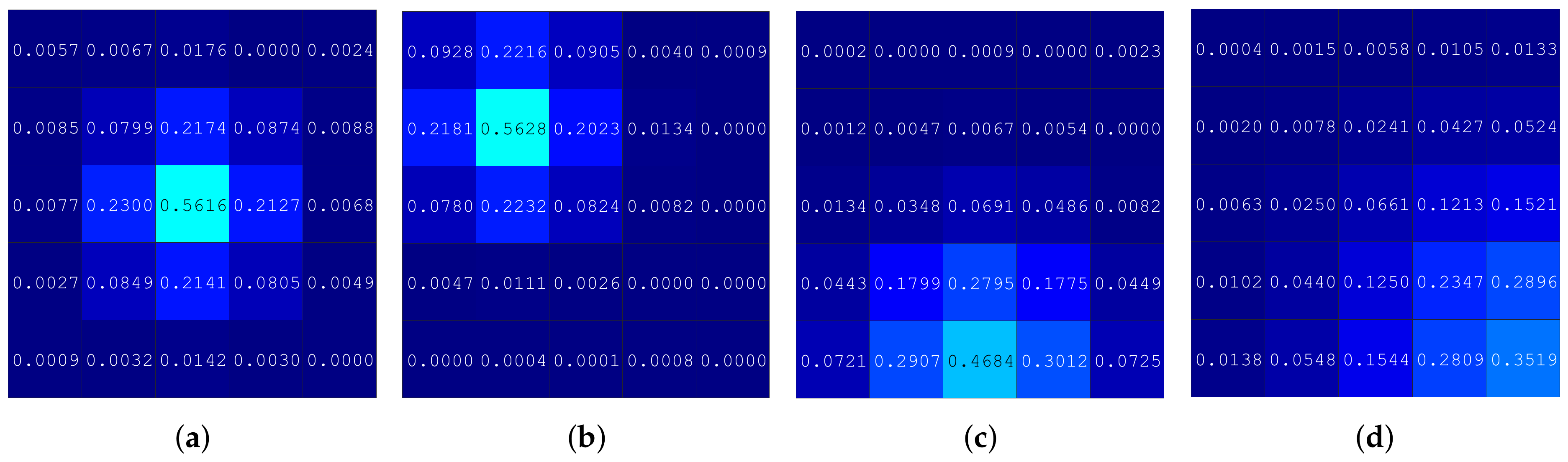
| Parameter | Setup #1 | Setup #2 | Setup #3 | Setup #4 |
|---|---|---|---|---|
| Distance between laser and PV array | 7 m | 7 m | 7 m | 7 m |
| Spot radius on PV array surface | 1.45 cell (29 mm) | 1.45 cell (29 mm) | 1.45 cell (41 mm) | 1.45 cell (62 mm) |
| Laser power | 6 W | 6 W | 6 W | 6 W |
| Location of highest irradiation cell | Center (Figure 1a) | Upper left side (Figure 1b) | Bottom center side (Figure 1c) | Bottom right side (Figure 1d) |
| 5S1010.4-A555555 | |
|---|---|
| Parameter | Value |
| Technology | Photovoltaic receiver |
| Optimal wavelength | 975 nm |
| Input power | Up to 50 W cm−1 |
| Output power | Up to 160 W |
| Power conversion efficiency () | Up to 36% |
| Dimension (A) | 51 mm × 52 mm |
| Unit price | $2000 |
| MDL-H-808 | |
| Parameter | Value |
| Technology | DPSS laser |
| Wavelength | 808 nm |
| Operation mode | Continous wave |
| Output power () | 3 W to 6 W |
| Beam diameter () | 8 mm |
| Beam divergence () | 3 mrad |
| Unit price | $1200 |
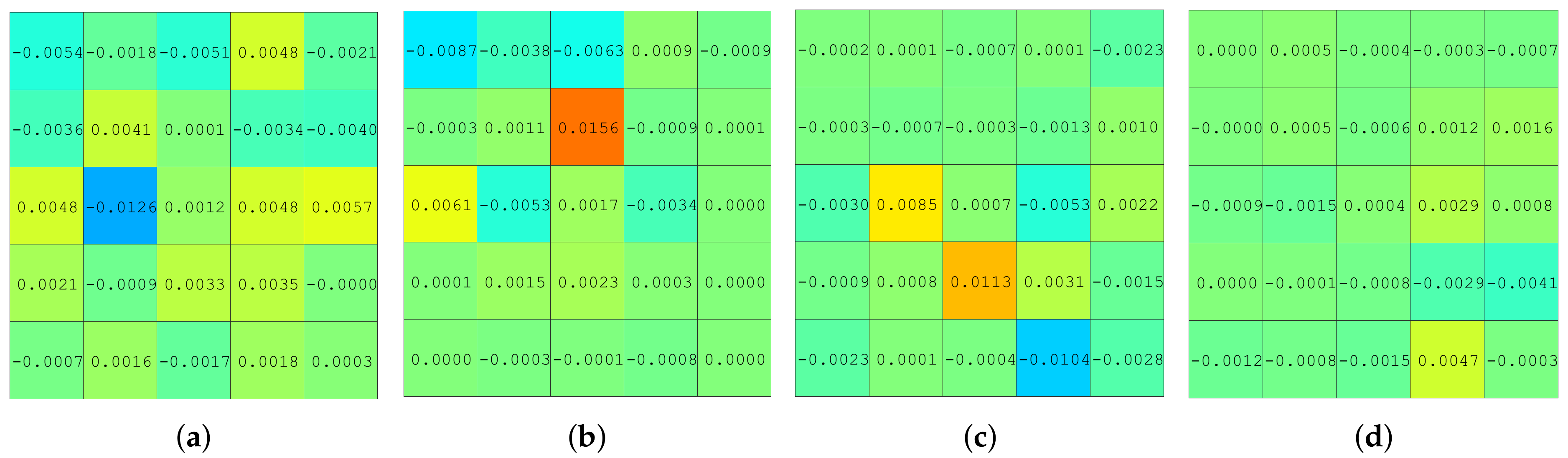
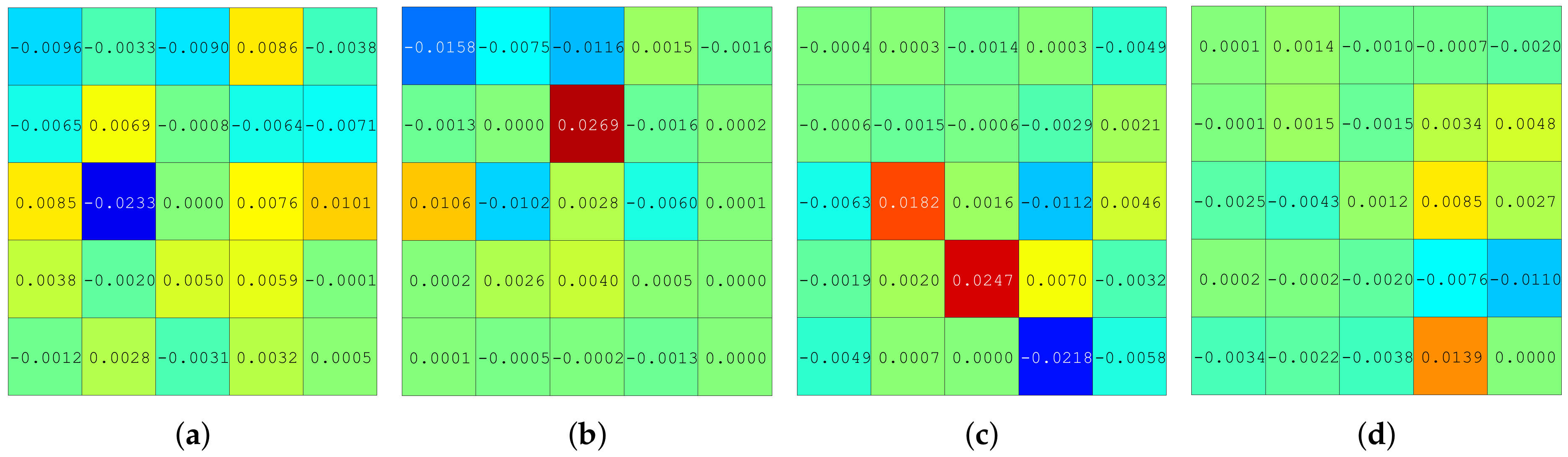
| Suitable Experimental Setup | Setup #1 | Setup #2 | Setup #3 | Setup #4 |
|---|---|---|---|---|
| Standard deviation of irradiation | 0.0098 | 0.0067 | 0.0068 | 0.0052 |
| Standard deviation of power | 0.0053 | 0.0037 | 0.0029 | 0.0019 |
| PTX | T1 | T2 | T3 | T4 | |
|---|---|---|---|---|---|
| MTP (kW) | 300 | 250 | 200 | 150 | |
| Location of the PTX (x, y, z) | (10, 18, 20) | (10, 10, 20) | (18, 10, 20) | (18, 18, 20) | |
| WPC | Range (θ, ϕ), (°) | (90–180, 0–359) | (90–180, 0–359) | (90–180, 0–359) | (90–180, 0–359) |
| Spacing (θ, ϕ), (°) | (1, 1) | (1, 1) | (1, 1) | (1, 1) | |
| HILPB characteristics | Diameter (m) | 0.01 | 0.01 | 0.01 | 0.01 |
| divergence (rad) | 0.01 | 0.01 | 0.01 | 0.01 | |
| PRX | R1 | R2 | R3 |
|---|---|---|---|
| MPQ (W) | 200 | 300 | 150 |
| Location of the PRX (x, y, z) (m) | (7, 12, 1.5) | (20, 16, 2) | (12, 20, 1.5) |
| PV array architecture | 5 × 5 | 5 × 5 | 5 × 5 |
| PV array surface area (m2) | 1 | 1 | 1 |
| Power conversion efficiency | 30% | 30% | 30% |
| Size of PV array | 1 m | 1 m | 1 m |
| Parameter | T1 | T2 | T3 | T4 | |
|---|---|---|---|---|---|
| R1 | WPC | (162, 189) | (173, 333) | (154, 283) | (150, 236) |
| Highest irradiance cell location | PV (0, −1) | PV (0, −1) | PV (−1, −1) | PV (−1, 0) | |
| RCPI of the pilot signal | 44.426 μJ | 46.678 μJ | 42.642 μJ | 39.836 μJ | |
| MDP | 289.8 kW | 248.25 kW | 185.4 kW | 129.9 kW | |
| MTE | 96.6% | 99.3% | 92.7% | 86.6% | |
| R2 | WPC | (153, 103) | (149, 56) | (161, 283) | (173, 153) |
| Highest irradiance cell location | PV (−1, −1) | PV (−1, −1) | PV (−1, −1) | PV (0, −1) | |
| RCPI of the pilot signal | 42.366 μJ | 39.836 μJ | 44.436 μJ | 45.678 μJ | |
| MDP | 276.3 kW | 216.5 kW | 193.2 kW | 148.95 kW | |
| MTE | 92.1% | 86.6% | 96.6% | 99.3% | |
| R3 | WPC | (173, 63) | (154, 13) | (150, 326) | (162, 279) |
| Highest irradiance cell location | PV (0, 0) | PV (0, 0) | PV (−1, 0) | PV (0, 0) | |
| RCPI of the pilot signal | 45.678 μJ | 42.642 μJ | 39.836 μJ | 44.436 μJ | |
| MDP | 297.9 kW | 231.75 kW | 173.2 kW | 144.9 kW | |
| MTE | 99.3% | 92.7% | 86.6% | 96.6% | |
Publisher’s Note: MDPI stays neutral with regard to jurisdictional claims in published maps and institutional affiliations. |
© 2021 by the authors. Licensee MDPI, Basel, Switzerland. This article is an open access article distributed under the terms and conditions of the Creative Commons Attribution (CC BY) license (https://creativecommons.org/licenses/by/4.0/).
Share and Cite
Kim, G.; Ashraf, I.; Eom, J.; Park, Y. Optimal Path Configuration with Coded Laser Pilots for Charging Electric Vehicles Using High Intensity Laser Power Beams. Appl. Sci. 2021, 11, 3826. https://doi.org/10.3390/app11093826
Kim G, Ashraf I, Eom J, Park Y. Optimal Path Configuration with Coded Laser Pilots for Charging Electric Vehicles Using High Intensity Laser Power Beams. Applied Sciences. 2021; 11(9):3826. https://doi.org/10.3390/app11093826
Chicago/Turabian StyleKim, Gunzung, Imran Ashraf, Jeongsook Eom, and Yongwan Park. 2021. "Optimal Path Configuration with Coded Laser Pilots for Charging Electric Vehicles Using High Intensity Laser Power Beams" Applied Sciences 11, no. 9: 3826. https://doi.org/10.3390/app11093826