Article

A UWB-Driven Self-Actuated Projector Platform for Interactive Augmented Reality Applications

School of Integrated Technology, Gwangju Institute of Science and Technology, Gwangju 61005, Korea
*
Author to whom correspondence should be addressed.
Appl. Sci. 2021, 11(6), 2871; https://doi.org/10.3390/app11062871
Submission received: 26 February 2021 / Revised: 17 March 2021 / Accepted: 19 March 2021 / Published: 23 March 2021

Abstract

:
With the rapid development of interactive technology, creating systems that allow users to define their interactive envelope freely and provide multi-interactive modalities is important to build up an intuitive interactive space. We present an indoor interactive system where a human can customize and interact through a projected screen utilizing the surrounding surfaces. An ultra-wideband (UWB) wireless sensor network was used to assist human-centered interaction design and navigate the self-actuated projector platform. We developed a UWB-based calibration algorithm to facilitate the interaction with the customized projected screens, where a hand-held input device was designed to perform mid-air interactive functions. Sixteen participants were recruited to evaluate the system performance. A prototype level implementation was tested inside a simulated museum environment, where a self-actuated projector provides interactive explanatory content for the on-display artifacts under the user’s command. Our results depict the applicability to designate the interactive screen efficiently indoors and interact with the augmented content with reasonable accuracy and relatively low workload. Our findings also provide valuable user experience information regarding the design of mobile and projection-based augmented reality systems, with the ability to overcome the limitations of other conventional techniques.

1. Introduction

Humans always seek to be more engaged with their surroundings to have fun, make social bonds, or gain knowledge. Therefore, different kinds of interface mediums have been developed throughout time to provide the sense of connectivity with different immersive levels [1]. Humans spend most of their time inside indoor spaces (e.g., homes, offices, schools, and cultural and entertainment facilities); therefore, creating interaction channels inside these places is essential.
Nowadays, we find interactive screens in shopping malls for visitors’ guidance [2]. Limiting the interactive experience to a fixed dimension screen could be helpful in a static environment, but it does not meet the dynamic environment requirement that demands interactions in different places. In [3], better utilization of indoor spaces to create more immersive interaction experiences was proposed utilizing spatial augmented reality (SAR), where projection technology was used for SAR applications to render augmented images over real-world surfaces. A commercially available example of a SAR system is ceiling-mounted projectors, which support interactions with projected screens used in schools and companies. This category of interactive projectors needs a special setup to guarantee precise calibration and works by tracking the user’s hand movements [4,5].
Even though using a single and fixed projector enables larger interactive surfaces, researchers have tried to enlarge the interactive envelope by proposing greater mobility in the projector unit. Everywhere Display [6] and similar developed techniques [7,8] proposed a steerable augmented reality platform to map augmented screens over different surfaces in a room-scale area. Image-based techniques are common among these platforms to detect a user’s position or limbs and enable interaction with augmented graphics. Even image-based techniques are one of the most accurate tracking systems; however, it limits users’ freedom in positioning themselves relative to the augmented screen. Thus, the interactive experience is bound by a fixed area in which users must stand to keep a clear line-of-sight with the camera view. This study [8] proposed a technique to use a second Kinect camera to resolve this problem, but still, the user could not move freely because of the physical limitation of the camera field of view (FOV). Moreover, the user could not perform interactions beyond the system’s physical setup.
Where to project is another issue. Researchers in [7] designed augmented graphics to be mapped over a human’s body and to be updated in real-time during their movement. Consequently, in [9], the augmented screens were mapped on the floor based on the interaction progress for single or multiple users as an informative system that helps the user explore effectively augmented surroundings. MeetAlive [10] presents an omni-directional display system considered adequate for a face-to-face meeting in a room, where the user could define the location of the augmented screen to any surface in the room for a more effective display. Some methods limit the users’ ability to choose where to project according to the display context, where others propose to vary the display content and limit the ability to dynamically change the augmented screen’s location (position and size). Not only where to project is important but also designing the projected content is crucial for AR applications. To boost the projected content’s impact, thoughtful design for the projected items plays an essential role in influencing the users’ cognition ability and, accordingly, their visual information’s interpretation and perception [11]. The variation of the spatial cognitive skills between users was found to change the gained benefit from an AR application’s content [12], which implies the importance of carefully designing each item within the projected content.
Interactive technology can be seen in modern museum exhibitions [13,14], where SAR is used widely with different implementation technologies [15,16]. Considering that a museum environment contains several exhibition halls where interactive content needs to be displayed in different locations, using many fixed or steerable projection-based AR could be a good solution. However, it is costly and requires effort for precise setup and calibration. The nature of the cyclic change of in-show content in each exhibition hall may require a continuous displacement of interactive equipment. Therefore, increasing the projector unit mobility may be a suitable solution utilizing only a single project to surpass the room-scale limit. Mobile interactive projection augmentation may be effective for a dynamic and varying-scale interactive environment. An example of using mobile projection indoors is shown in [17] to map accurate images on 3D objects.
In our study, we chose the ultra-wideband (UWB) wireless network to locate objects in 3D with a moderate tracking accuracy as long as these objects are present inside the tracking envelope. This tracking network provides greater freedom for users to move and perform interaction within the tracking envelope and not restrict their movement to a specific area. Besides, the UWB wireless network governs the mobile projector platform’s navigation and widens the interaction area by converting passive indoor surfaces to interactive ones. Following this strategy results in a comprehensive interactive environment within a single room and allows the interaction to be designed in a symmetric way outside room boundaries. We name the described mobile projector platform as a UWB-driven self-actuated projector (USAP). It supports a mobile augmented screen in any position according to the user’s desire. The user could define the interactive window and start interacting with the augmented screen using a hand-held input device. We designed the USAP as an information provider platform, where displayed content changes according to the detected position (e.g., defining hall number, surface ID, and USAP spatial position). Therefore, it could be an effective assisting platform for people such as tour-guides or teachers to present interactive, informative content to an audience or group of students for relatively large-scale indoor spaces.
This study aims to enhance interaction capabilities within a single room and suggest a scheme that can enlarge the interactive area beyond the room-scale systematically using a commercial-of-the-self, cheap, and portable technology to meet the need of large-scale interactive areas. Additionally, we seek to give the user more freedom to use any position to perform interactions without limiting movement. We also seek to support the user with a dynamic ability to define an augmented screen’s position and dimensions within any surface indoors, where a light-computational UWB-based calibration algorithm runs to localize the augmented screen.
To achieve our study goal, we conducted a study to answer the following research questions (RQs):
  • RQ1: How effectively deploying a UWB wireless sensor network help to convert passive surfaces into interactive ones for a dynamically change interactive indoor environment?
  • RQ2: How the deployment of a UWB network propose a solution to overcome limitations in conventional interactive spatial projection systems?
  • RQ3: What does system performance in terms of interaction accuracy, interaction time, workload, and system usability indicate about the system design and a user’s interaction experience?
To address these questions, we recruited 16 participants to experience our system in a laboratory-controlled environment to test the system’s different aspects. The analysis of the collected data alongside participant behavior observations led to the following contributions:
  • We developed an accurate, mobile, user-friendly, and expandable projection-based AR interactive system for indoor environments by deploying a UWB wireless sensor network and designing a UWB-driven self-actuated projector platform.
  • We designed a UWB-based, and light-computation calibration algorithm to enable interaction in any location with projected screens.
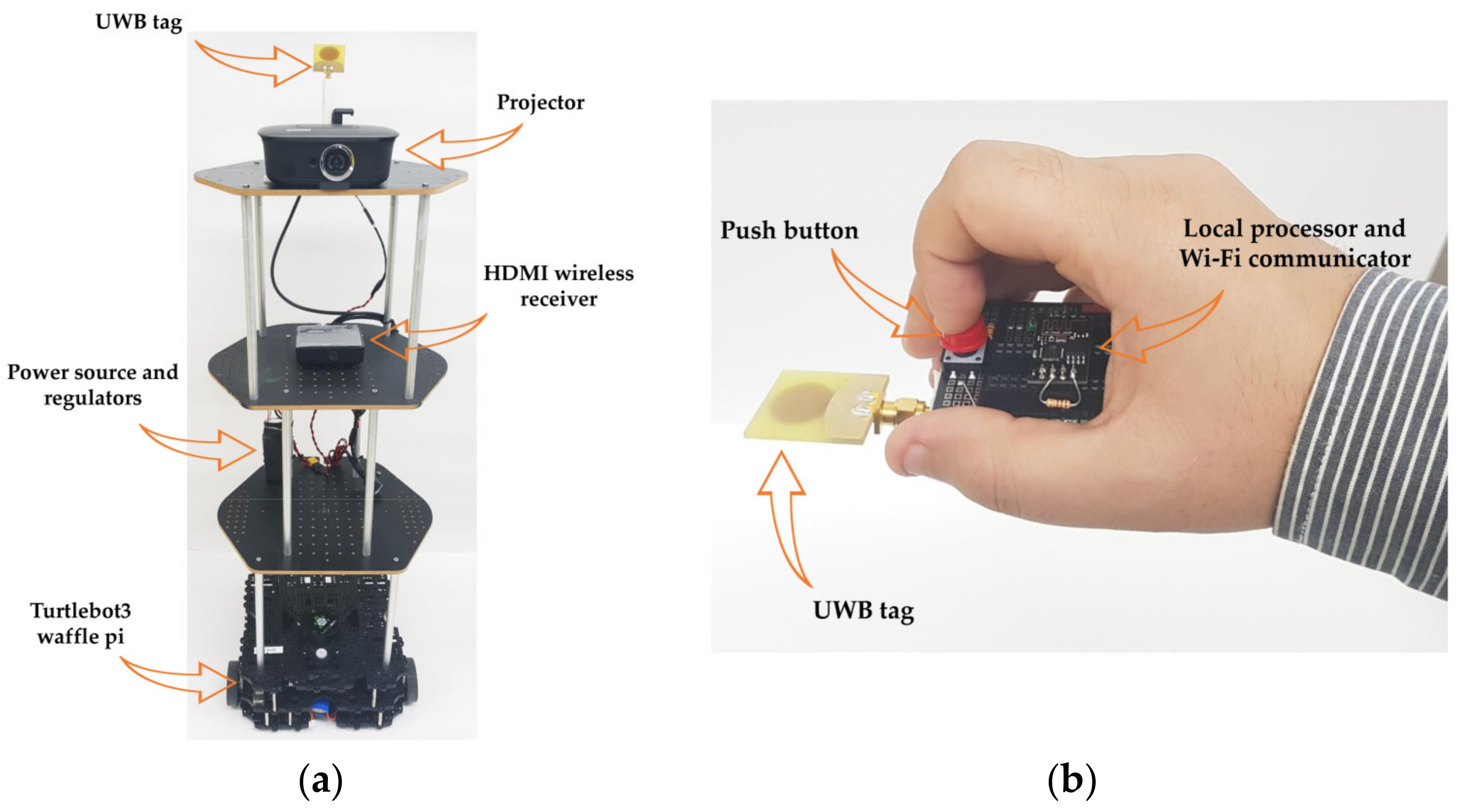
  • We designed a hand-held input device that allows the user to define the projection location and the size in any position indoors and that performs mid-air interaction functions such as pointing, triggering, dragging and dropping, and swiping.
This paper is organized as follows: Section 2 describes related work. Section 3 presents the UWB wireless sensor network ’s deployment to enable interaction over passive surfaces and demonstrates our USAP platform and input device design. The mathematical basis and structural data interaction management scheme are explained in Section 4. The experiment design is found in Section 5. Results are listed in Section 6. Section 7 presents the discussion and candidate system applications. Limitations and future work appear in Section 8. A conclusion is provided in Section 9.

2. Related Work

2.1. Informative Augmented Reality

Augmented reality (AR) is defined as a field where humans can perceive an augmented real-world experience by superimposing digital components over the physical world. Using AR systems appear useful in various fields that deliver information to users. For industrial purposes, AR can assist workers by giving real-time instructions through visual clues. This study [18] designed an AR system that instructs workers on the welding quality assurance process. This system requires a predefined and fixed location for installing the projector unit where the projected content is chosen according to the welded part characteristics. The authors of [19] used an AR system to detect thermal leaks by providing visual data to avoid common accidents in the workplace; similarly, the projector unit headed towards the area of interest. For educational purposes, a famous example of using AR is the interactive board in classrooms [20], where it helps students to become more involved in the in-class activity and increase their attention. However, the projection-based interactive board usually suffers from tracking sensor occlusion and the projection beam’s blockage problems. AR also appears to help in the early stages of the designing process, as presented in [21], where augmenting animated graphics contributes to building up a prototype level of interactive kinetic art. This design affords a limited interaction area due to the use of a stationary and heavy projection unit and the restricted field of view of the tracking camera. Also, some users found it inconvenient to use the mobile device to designate the desired workflow in a small workspace. In the medical field, AR’s influence cannot be denied, as it can assist in medical education [22] by displaying anatomical information over a tracked body-parts. This type of application needs a relatively large installation area because it contains many projection units, making it not preferable to displace this setup if required. For cultural applications (e.g., augmenting a museum’s content), an AR system supports items on display by providing a supplementary explanation in different forms; in [15], the authors placed the projection unit behind a large screen to allow museum visitors to manipulate a detailed 3D model using indirect touch control. A customized and affordable wall where direct touch triggers the display of augmented visual material providing historical information was presented in [16]. In both examples of museum AR systems, the interaction is confined to a single place and servers one interaction purpose. We selected the previously mentioned literature under the category of projection-based AR, as it is the same AR-type as in our study. Most of the presented work has a fixed or limited interactive workspace. Therefore, it is crucial to figure out the different mobility levels of projection-based AR systems looking for expanding the interactive area.

2.2. Mobility Levels of Projection-Based AR

Researchers in [23] summarized the mobility levels of projection-based AR and divided them into four main categories: Environmental projectors, moveable projectors, hand-held and body-worn projectors, and self-actuated projectors.
Environmental projectors are confined to one location with or without the ability to steer them to augment graphics over one or multiple surfaces indoors. Ojer et al. [24], presented an example of a fixed projector installed to support manual component assembly; this technique reduces worker error in assembly, especially when training a new worker or assembling a new board model. A steerable type effectively augments multi-surfaces; in [25,26], the researchers proposed a technique for registering suitable projection surfaces, making it easier for the user to display the graphical content. These environmental projectors suffer from a limited projection area, which is usually not more extensive than a room, which has moved researchers to examine more portable solutions.
Moveable projectors are commercially available through different manufacturers. One example is from the Hachi company [27], whose latest interactive projector allows the user to interact with the displayed augmented screen on a floor or wall, depending on how the projector is set up. Users could carry it and place it at any location. Even though the mobility increases, the user still needs to place the projector in different locations.
For more flexibility, hand-held and body-worn projectors are explored in [28,29]. Combining a pan-tilt actuated projector with the Hololens AR headset enlarges the display field of view [30], where the local augmented display is projected onto the physical world, then various levels of content’s manipulation and sharing are possible. For these projectors, the user must have the projector attached to their body when augmenting a surface is a simple task by directing the projector over that surface; however, hand-held and body-worn projectors cause a burden on the human body that could exhaust the user, mainly if used for a long time.
A self-actuated projector (SAP) can navigate on its own. Usually, a robotics platform is used to provide the required mobility. Tripon [31] is a commercially available projection robot that can project an 80-inch screen from 3 m, and the user can control its movement and change the projection parameters via mobile application. Researchers propose using SAP to scan for the best projection walls [32], allowing humans to better perceive the augmented content. Other studies propose SAP’s usage to guide users reaching their destination by providing visual clues over different surfaces [33,34]. Following the same concept, human-aware path planning has been proposed for a ground robot that can navigate to a target position and avoid harming users if they stand in the projector’s throw field [35]. Besides, the authors propose SAP using image-based tracking for museum-related applications. However, several ambiguities emerge: How can users perceive interactions with such a platform? Where are interactions performed? How can users optimize the interaction location? The same study considered the robot as an initiator that provides augmented information for preplanned places and neglecting the fact that humans may need to ask for supplementary information. Designing an SAP platform in a dynamic environment, such as a museum, requires a focused understanding of human needs and detailed interaction practicality testing.
Like ground robots, flying robots can work as hosts for the projector unit [36]. Drones were used to support indoor and outdoor interactive displays [37,38]. In [37], the user stood under a fling robot and interacted with projected content around them using hand gestures. Using drones has its safety concerns, especially when flying indoors with static and dynamic obstacles. It is obvious how an SAP platform moves projection-based AR beyond room boundaries. Humans do not need to carry or wear anything heavy, as SAP’s automatic ability to navigate makes the interaction experience more fixable without performing any prior setup. The power consumption, general maintenance, and usage context are the main issues to be considered to make an SAP platform commercially available on a wide scale. Our study uses the SAP platform and other proposed study components to have an interactive experience that considers human interaction needs, serves in wide interactive spaces, and supports dynamically changing environments.

2.3. Tracking Systems for Interactive Spatial Projection

Perceiving augmented graphics in the physical world using visual feedback can be combined with the interacting ability using hand movements, leg movements, or body gestures. Different types of sensing technologies exist to afford interactions with projected screens. Camera-based detection is the most commonly used technique for tracking a user’s limbs or body, thus enabling interaction with a projected screen. Gonçalves et al. [39], placed a Kinect camera in front of users to detect their hand pointing or footsteps toward or on a projected screen. In another study, a set of four projectors was placed under the floor [40], and a camera tracked the places where the user’s hands and feet were in contact with the projected content. Interpersonal interactions for children with special needs were studied in [41], where a large interactive floor projection with cameras to detect the interaction was used. Using a camera-based technique guarantees a high detection accuracy, but users must stand within the camera’s field of view, limiting their freedom to move. Users also must take care not to block the camera’s view with their body so that cameras can keep tracking their hands [6,25]. Such restrictions affect the intuitive interactions with the projected screen. To avoid this limitation, the camera and the projector must face different plans [39], which usually requires a particular setup and limits the interaction area.
Another category of the tracking system is capacitive sensing, e.g., Wall++ [42], where walls can be modified to support interactions by spreading, over a wall of interest, an electrode array connected with a control circuit placed outside the wall to detect interaction coordinates. Additionally, the modified wall’s electromagnetic sensing enables this system to detect the appliance’s status and localize people indoors. This infrastructure requires excessive effort and cost to prepare multi-walls. Even though close interaction with the modified wall has good accuracy, it is not the same for far interactions, where accuracy decreases dramatically. The addition of different types of sensors over walls to detect interaction positions is described in [43].
Infrared-based trackers like HTC Vive [44] supports room area tracking with high precision. Using this system requires special cautions when installing lighthouses choosing the proper height and orientation. Also, it requires removing or covering any reflective surface within the tracking envelope to achieve better tracking results. Using the HTC Vive controllers has a dependency on the head-mounted display location, which must stay within the tracking area even though it is not used for interaction purposes. The optimal tracking area is placed on the center of the lightning houses’ setup; therefore, tracking near the edges has relatively noisy measurements [45].
We adapted UWB sensing technology to address the above-mentioned sensory limitations, which is considered one of the best available for indoor tracking [46]. UWB sensing supports utility tracking [47], so available tracking data are not restricted to one room. In this study, a UWB wireless network is used as a tracking system to navigate our USAP platform and enable interaction with the projected content. The ease of deploying UWB sensors supports expanding the interaction envelope systematically if needed. To our knowledge, we are the first to use a UWB positioning system in the room area to enable accurate interactions with projection-based augmented content over a dynamically changing user-defined projection screen utilizing different surfaces around. Then we propose the possibility to expand this concept to create an intuitive interactive environment.

3. System Design

3.1. UWB Wireless Sensor Network Infrastructure Configuration

In this work, the UWB positioning system is composed of 6 anchors (A1–A6), 1 master (M), and 2 tags (one for the USAP platform and one for the user’s hand-held device). The chosen UWB positioning system is developed by Ciholas [48]. The Ciholas UWB module comes in a single hardware unit and plays multiple roles (such as anchor, master, and tag) by means of varying the software, and each module mainly consists of a Decawave’s DW1000 transceiver and an ARM’s 32-bit Cortex-M4 processor. The master is responsible for controlling and collecting the time of flight (TOF) measurements based on the time difference of arrival (TDOA) technique among anchors and tags; after that, it sends the collected TOF values to the server for position processing via serial communication. According to Ciholas, their UWB positioning system can track up to 48 tags with 10 anchors and 1 master at a 20 Hz location update rate and achieve a position accuracy of about +/−0.1 m laterally and about +/−0.2 m vertically in a typical gymnasium-size environment.
We deployed a total of 6 anchors in a room to exhibit 3D position tracking. Anchors were installed over two perpendicular walls; this installation reveals a cost-effective physical effort to track 3D spaces and decreases the non-line-of-sight and multi-path effects while performing UWB signaling among anchors and tags. Only the three anchors are installed on ground corners, while three other anchors are attached on the ceiling parallel to the ground anchors. All six surfaces (S1–S6) can be tracked under the L-shape infrastructure to exhibit reliable user interaction. The UWB position system’s deployment is possible in a similar fashion from a single room to multiple rooms. Only the master of each room needs to be equipped with a Raspberry PI as a local server to communicate with the central server on the WLAN for position processing. Besides, as Ciholas UWB positioning system can track up to 48 tags, multi-agent tracking is also possible when it is required to add more than one USAP platform and multi-users in our presented indoor interactive system. Figure 1 shows the detailed UWB wireless sensor network installation for a single room (Room 1) while proposing a multiple room (Rooms 1–4) configuration concept.

3.2. Design of UWB-Driven Self-Actuated Projector Platform and Input Device

The USAP platform was built with the Turtlebot3 waffle-pi robot [49] as a mobile base. A tower-like structure was formed to create portions for the components, such as the projector, the wireless receiver device, the UWB tag, and the power source. Figure 2a describes the USAP platform, and Table 1 elaborates the specifications of its Components, where a commercial-off-the-shelf projector is placed on the top of the USAP platform and connected to a wireless receiver through an HDMI connection to display content at 720p resolution. The USAP platform navigates between points whenever it receives a new target point utilizing the UWB positioning system. Figure 3 explains the robot operating system (ROS)-based [50] pipeline to navigate the USAP.
A hand-held input device, shown in Figure 2b, is equipped with a standalone UWB tag to track the user’s hand position. Additionally, it integrates a microcontroller to detect push button presses and update its status to the server PC through Wi-Fi communication. The designed input device allows the user to perform pointing, selecting, dragging and dropping, and swiping (based on the user’s hand motion patterns). Both the USAP platform and hand-held input device can run on average more than two hours before replacement of batteries are required.

4. Mathematical Basis and Interaction Management

This section explains the mathematics for estimating the boundaries of variable-size projected screens over different surfaces. Finding the projected screen boundaries helps to localize items within the projected screen and thus enable interaction. Our proposed system allows the user to customize the projected screen’s size and location, so the USAP platform navigates to meet the user’s display desires. The method used for projected screen calibration, the self-actuated projector navigation, and the mid-air user’s hand gesture detection performance are presented in this section. Finally, an interaction management scheme on how users perform interaction and how data handled in central and local servers are illustrated.

4.1. UWB-Based Calibration Algorithm and Interaction Detection

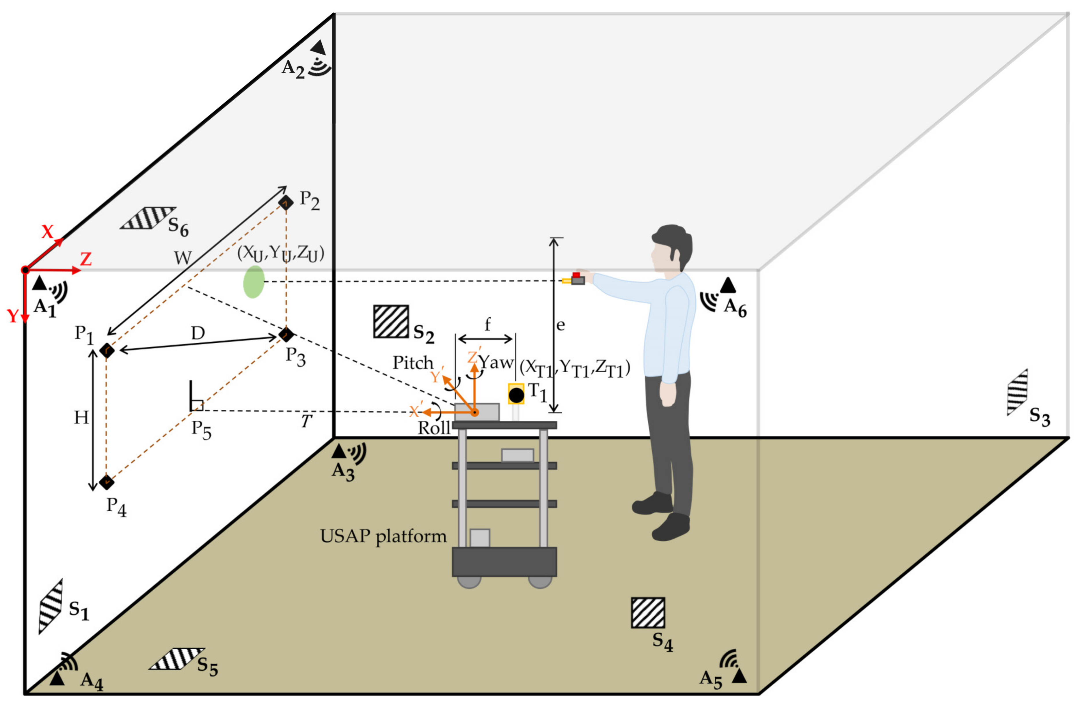
To estimate the projected screen boundaries, the USAP platform needs to be localized within the room by representing Tag 1 (T1) with position coordinates as (XT1, YT1, ZT1). Where defining the interactive surface ID tells about the USAP yaw angle around its local frame Z-axis.
Following the setup in Figure 4, the projector beam source position is (XT1, YT1, ZT1–f), and the Y-axis coordinate for the projected screen points P3, P4, and P5 equal to the vertical distance from the ceiling to the beam source, is (e), given that the throw beam offset is 100%. The throw distance (T) on the Z-axis from the USAP platform defining the diagonal distance of the projected screen (D) by using information given by the projector’s manual (Table 2).
We use the curve fitting function to find the best polynomial representation for the relation between T and D, where c0, c1, c2, and c3 are coefficients of third order polynomial:
D = (c3 × T3) + (c2 × T2) + (c1 × T) + c0.
Using the projector aspect ratio 16:9 and from the projection geometry, we can write two equations as follows:
(9 × W) − (16 × H) = 0
D − √ (W2 + H2) = 0
where W is the projected screen width, and H is its height. By updating the value of D based on the USAP position and solving (2) and (3), we could solve for W and H:
W = √ ((256/337) × D2)
H = (9/16) × √ ((256/337) × D2).
Projected screen boundaries can be defined by finding the coordinates of points P1, P2, P3, and P4:
P1 = [(XT1 − W/2), (e − H)]
P2 = [(XT1 + W/2), (e − H)]
P3 = [(XT1 + W/2), e]
P4 = [(XT1 − W/2), e].
When the user interacts with an augmented image, the user’s hand position can be represented as a pixel location in that image to define the interaction spot. Therefore, mapping each point inside the projected screen from UWB coordinate representation to pixel representation is the next step. If a user interacts with the projected screen at UWB coordinates of (XU, YU, ZU), the pixel location corresponding to the user’s touch is found by the following:
  • First, find the relative displacement of the user’s hand position from point P1.
    Displacement in X direction = XU − (XT1 − W/2)
    Displacement in Y direction = YU − (e − H)
  • Second, map the displacement in each axis to find the corresponding pixel coordinates. Map the projected screen width (W) to the number of pixels in the X-axis direction (M) and the height (H) to the number of pixels in the Y-axis direction (N) (e.g., screen resolution is M × N = 1920 × 1080 pixels). Displacement in the X and Y directions can then be represented as the user’s hand position in pixels (XM, YN).
    XM = Displacement in X direction × Pixels per centimeter in X direction, where Pixels per centimeter in X direction = M/W
    YN = Displacement in Y direction × Pixels per centimeter in Y direction, where Pixels per centimeter in Y direction = N/H
These calculations can be repeated when interacting with S2, S3, and S4, considering the axes’ difference from one wall to another. When projecting on S5 or S6, the same governing equation controls the interaction except for the ability to vary the yaw angle for the USAP freely according to user’s desires.
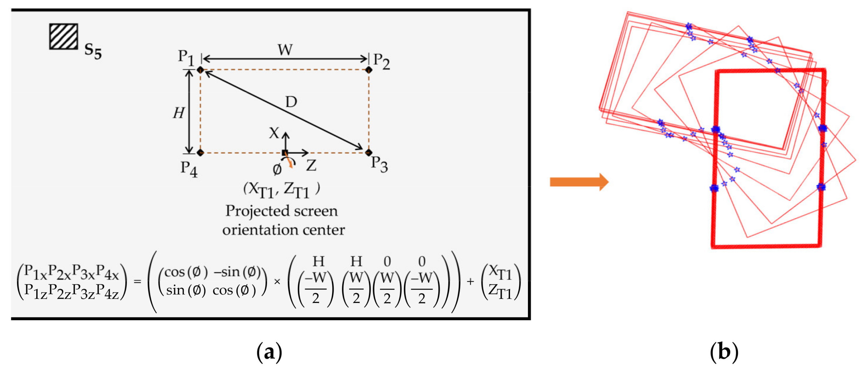
If the user seeks to interact with S5, the orientation angle of the USAP platform around the local Z’-axis influences the location of the projected screen, so a 2D rotation matrix is applied to find the new boundaries for the projected screen (Figure 5).
Four points coordinates = (2D orientation matrix × Displacement matrix from orientation center) + Orientation center coordinates
If the USAP platform is moving continuously between different surfaces and projecting visual contents, the user has the ability to interact directly at any location of the projection. Since the previously written equations can calibrate the display content dynamically for an indoor environment, we call it the UWB-based calibration algorithm.

4.2. Navigate the USAP Platform to Customize the Projected Screen

An important feature in our system is the ability of the user to customize the projected screen. Customizing means finding the proper location on the projection surface and defining the screen size. To illustrate the way it works, first, the user must activate the customization mood by double-clicking using the hand-held input device, where the duration between the two clicks must be less than 2 s. The user defines the projected screen location and size by selecting two diagonal points; however, the system must recognize the selected interaction surface throughout the user’s two designated points. Therefore, the corresponding coordinates of the two diagonal points are then compared (e.g., user input point1 = (XUI1, YUI1, ZUI1); user input point2 = (XUI2, YUI2, ZUI2)). We must then find the displacement in the X, Y, and Z-axes coordinates. For example, if the displacement in the X and Y axes is larger than the threshold1 value (e.g., threshold1 > 0.7 m) and displacement in the Z-axis is less than the threshold2 value (e.g., threshold2 < 0.3 m), then the user is assigning points on S1. Using this information, the USAP platform corrects its heading to this surface and inversely finds its desired spatial location using the user’s two input points, as follows:
  • Find the diagonal distance between the two designated points.
W = |XUI1 − XUI2|, and H = e − min (YUI1, YUI2). then D = √ (W2 + H2)
  • Similar to (1), throw distance (T) can be calculated using the projected screen’s diagonal distance (D). Since X- and Z-axis coordinates must be sent to the USAP to navigate to the target point and project on S1.
USAP X-axis coordinate = USAPX = min (XUI1, XUI2) + W/2
USAP Z-axis coordinate = USAPZ = T + f
A similar calculation is required if the user intends to perform interactions with a different wall in a different room; slight changes must be made for the axes’ change according to the interactive surface.

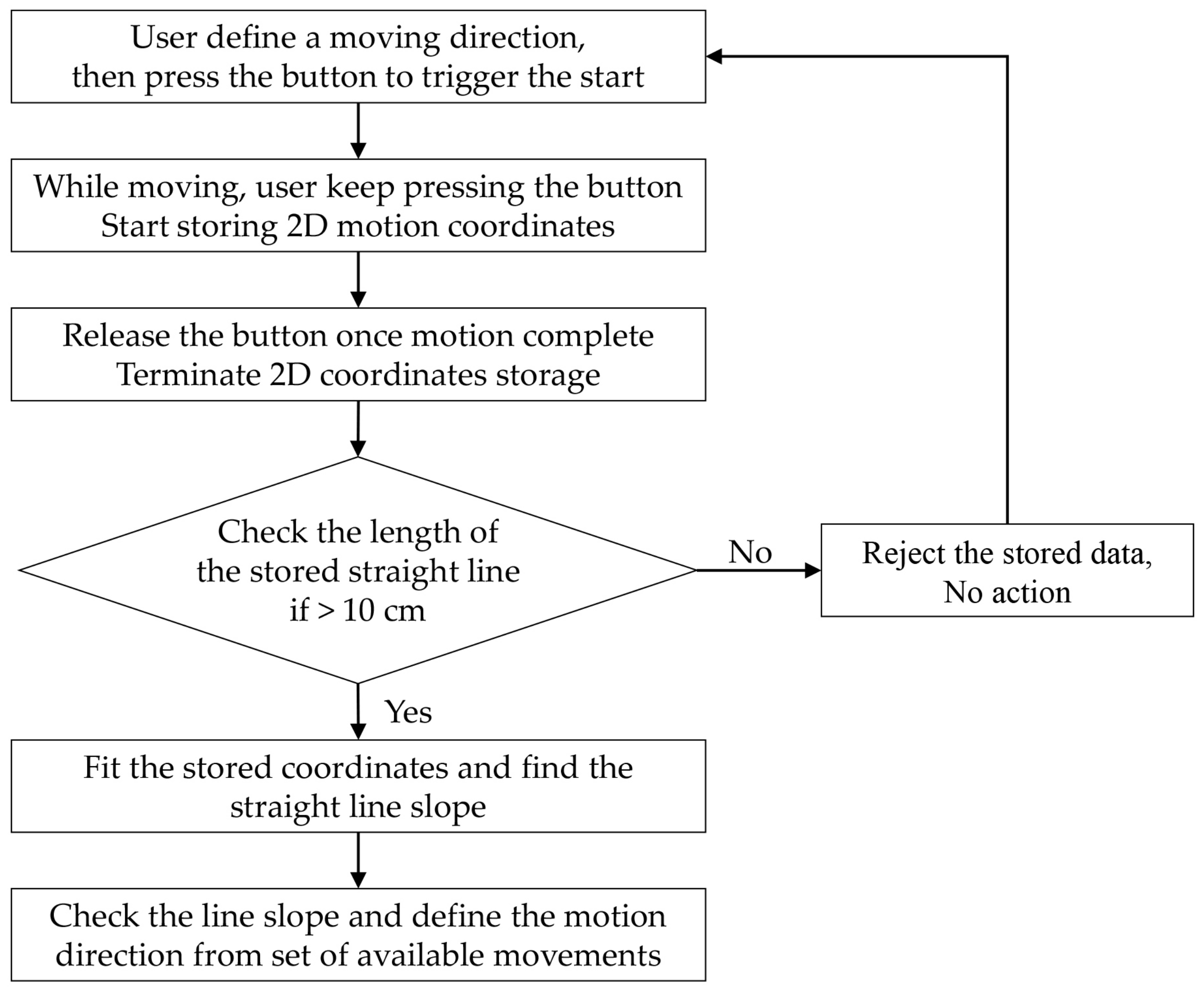
4.3. Algorithm of UWB Based Mid-Air Hand Gesture Detection

Finding the representation of the user’s hand position over the projected screen (Section 4.2) supports functions like pointing, triggering, and dragging and dropping. Moreover, detecting simple hand gestures in the form of straight-line swipes can be achieved using our hand-held input device. Using the push button integrated into our input device, the user can click it to start, then move their hand in four different directions (right, left, up, and down), keeping their finger over the push button. Once the hand motion is complete, the user can release their finger from the push button. While the push button is being pressed, our system stores the 2D coordinates of the moving hand, and once the user releases the button, a fitting algorithm runs to determine the slope of the generated straight-line, which defines the motion pattern. To minimize the error created from UWB positioning accuracy, we discard the stored data when the separation between the start and end points is less than or equal 0.1 m (Figure 6).

4.4. Interaction Management in UWB-Based Pervasive Computing Environment

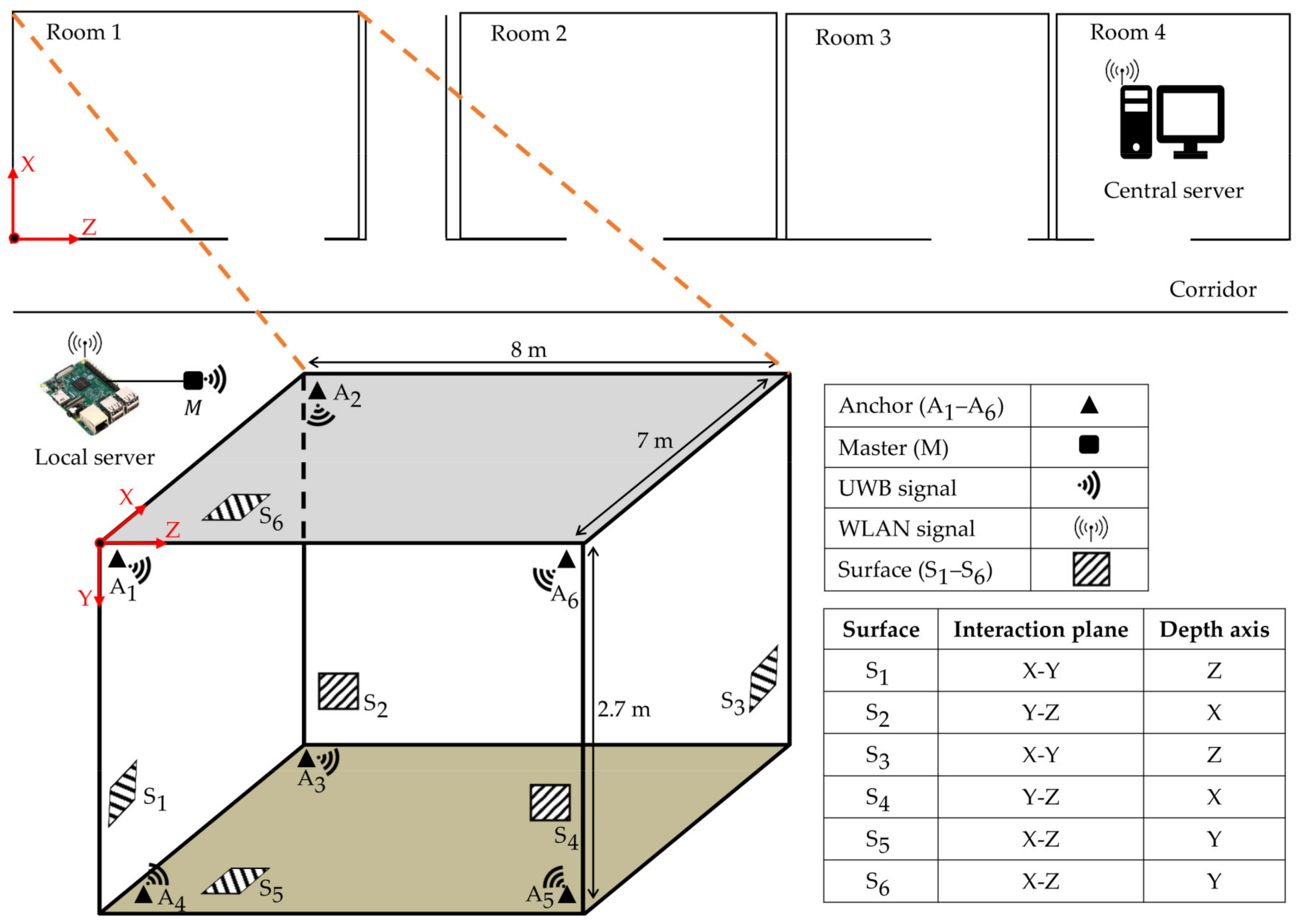
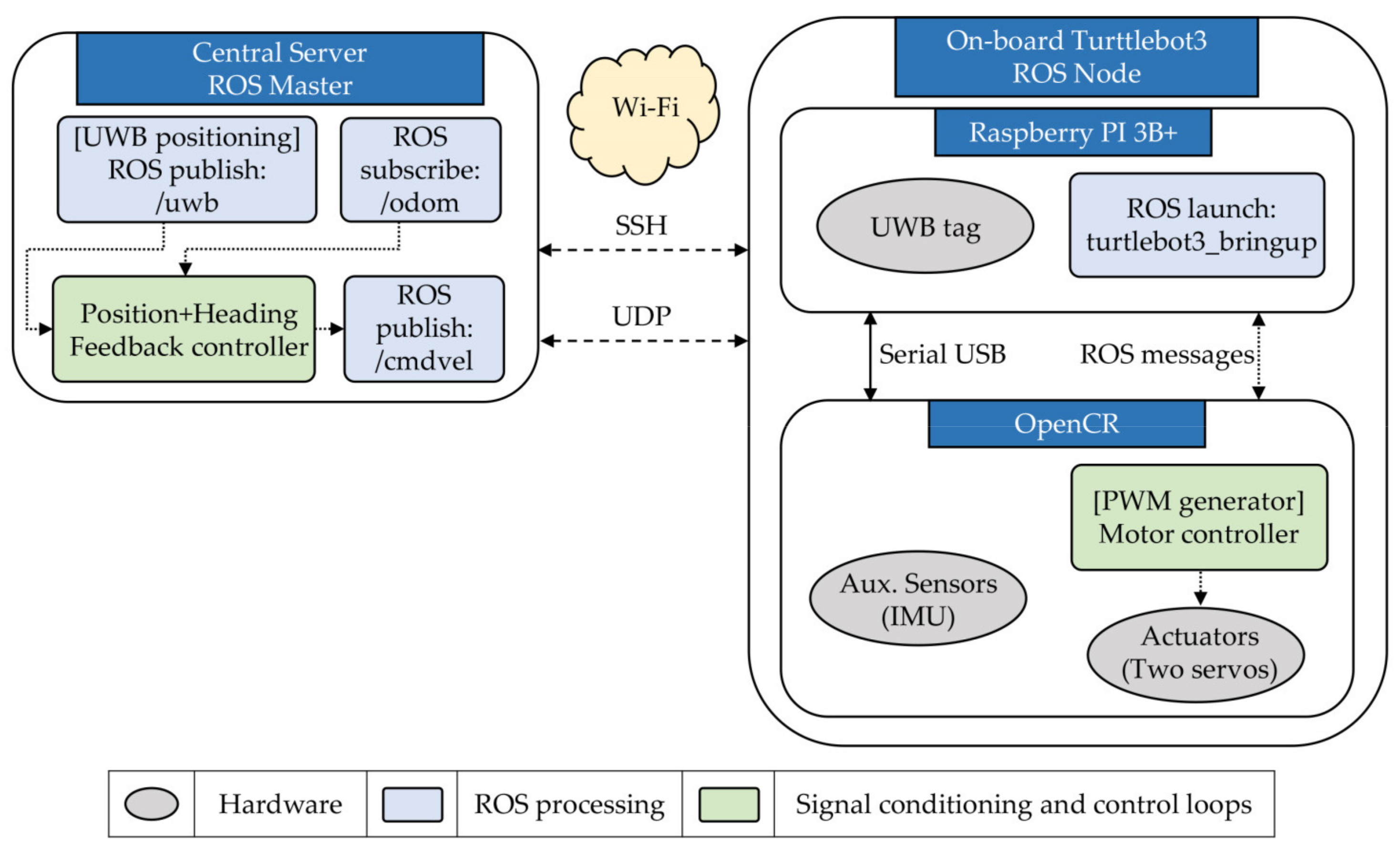
An interaction management scheme needs to be implemented to regulate the interaction process inside different interactive spaces (e.g., rooms or exhibition halls). The central server and the distributed local servers perform data handling and processing among all other system parts. The local servers are connected to the master nodes (Figure 1) and run the UWB positioning algorithm to update both user’s hand and the USAP platform positions. In the meantime, each local server delivers the positioning information to the central server using Wi-Fi communication, where different threads run parallelly to update the display content, control the USAP platform navigation, and perform calibration of the projected screen. The projected content is updated according to the USAP platform’s current position and orientation. Assume the USAP platform can serve in an exhibition environment where a pre-defined interaction content needs to be projected for each artifact. Therefore, the intended projection content can be automatically assigned by switching between different pre-designed interactive user interfaces (UIs) when defining the robot position and orientation inside the central server. The central server transmits the projected image wirelessly to the HDMI wireless receiver. Our system not only provides the possibility to interact with a projected screen but also to customize the location of the screen. The user designates two diagonal points anywhere to define the screen boundaries then the USAP platform navigates to the most proper location to deliver the desired screen (Section 4.2). The central server communicates with the USAP platform using Wi-Fi communication and uses ROS messaging to control its navigation path. With any movement for the USAP platform, a re-calibration for the projected screen is needed. The details of how to perform this UWB-based and light-computational calibration are described in (Section 4.1). 
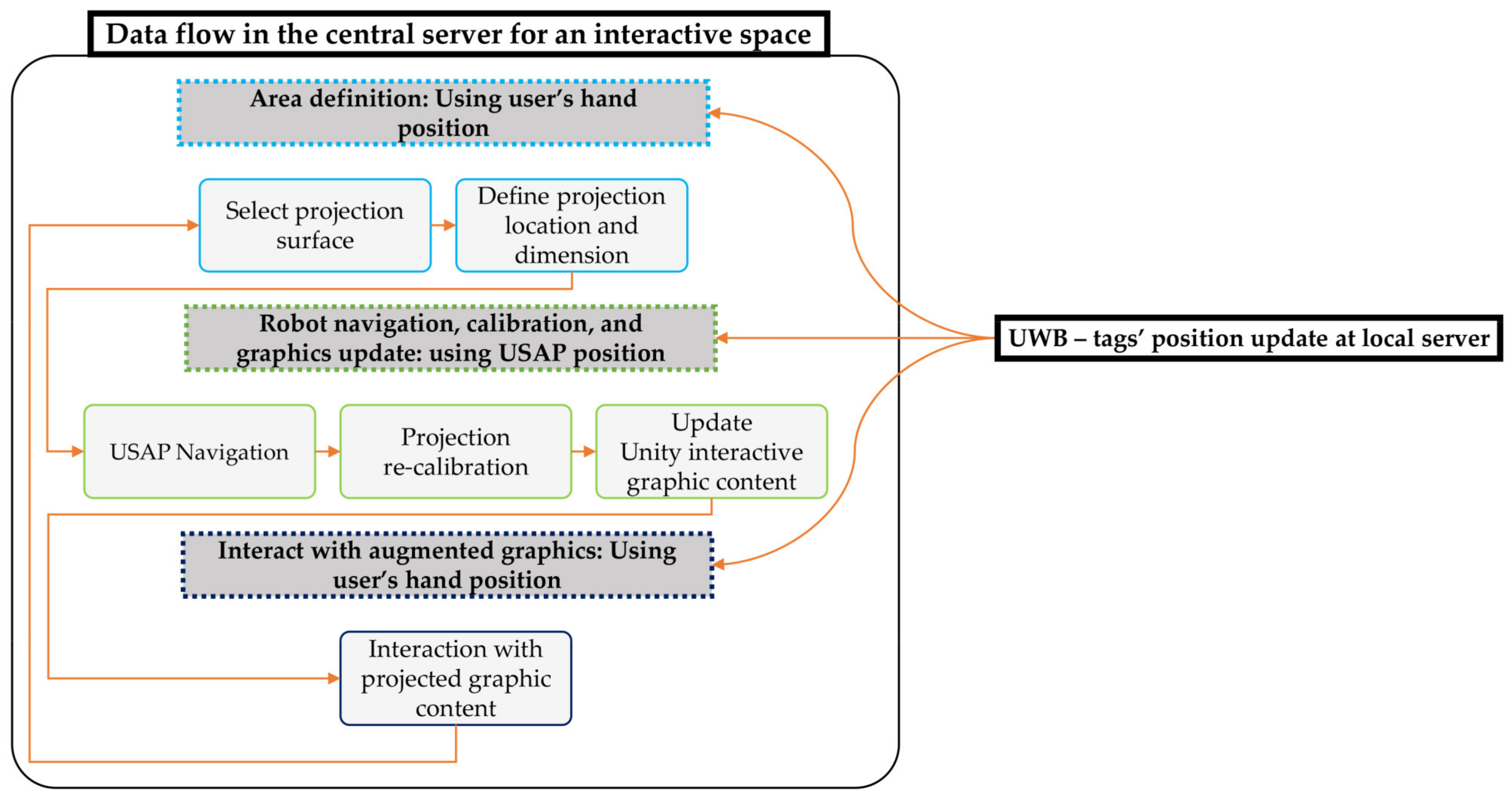
Figure 7 describes the complete data flow inside the central server for an interactive space. It shows the interaction management scheme that combines the user designation of the projection region of interest, navigation of the USAP platform, calibration for the new projected screen, and finally, detecting the interaction according to the user’s intent (Section 4.3). Interaction detection runs through Unity software, which is used as a graphics handler; collisions can be detected between the designed graphics location and user intervention position. The UWB positions of the user and the USAP are crucial information for all sections. Similar data flow can be replicated when required for multi-interactive spaces under the control of both the central server and the distributed local servers.

5. Experimental Design

5.1. Demographic Information and Procedure

Sixteen participants were recruited to perform this experiment. Participants’ age ranged between 25 and 38 years old (M = 28.75; SD = 3.29; Gender: Male = 11; Female = 5). All were postgraduate students with diverse technical backgrounds (engineering, bio-medical, physics, etc.) and nationalities. Participants did not report any mobility problems (e.g., problems using their hands), and all of them used their right hand for performing the interaction. Our system would be used mainly for interactive demonstrations or education purposes and supposed to be used by the trained people. Therefore, testing our system with different population groups was not essential. Each participant was compensated for an hour of their time with a gift that cost on average $10.
An experiment of four stages was designed to evaluate our system performance. In the first stage, interaction accuracy, interaction time, and the user’s workload were tested while varying the user’s relative interactive distance with the projected screen. In the second stage, we tested the projected screen’s customization function and the interaction performance in the presence of UWB-based calibration under the same criteria as in the first stage. The USAP navigation accuracy, navigation time, and the difference between the user’s desired designated screen and the actual projected screen were reported as well. In the third stage, we evaluated the hand-held input device performance by testing its swiping accuracy in different directions and measuring the user’s workload performing this task. In the fourth stage, participants were asked to evaluate our system’s overall experience using a system usability scale. Participants were instructed to take a five-minute break during the transition between experimental stages while the experimenter setup the software and hardware needed for the next stage.
To reduce the learning effect, we designed a counterbalanced within-group experiment by making participants undergo the four stages and shuffling the order of the first stage’s sub-parts (interacting from close and far distances). Before starting the first stage, participants provided their personal information by answering preliminary questions through a pre-designed online survey using the Survey Monkey platform. They were then asked to read an explanation describing the general use of our system, UWB tracking technology, the various hardware components (e.g., the USAP platform and the hand-held input device), and mainly what they will be asked to perform during the experiment.
The experiment was conducted in a controlled laboratory environment, where six UWB anchors were installed in an 8 × 7 m2 room, as illustrated in 
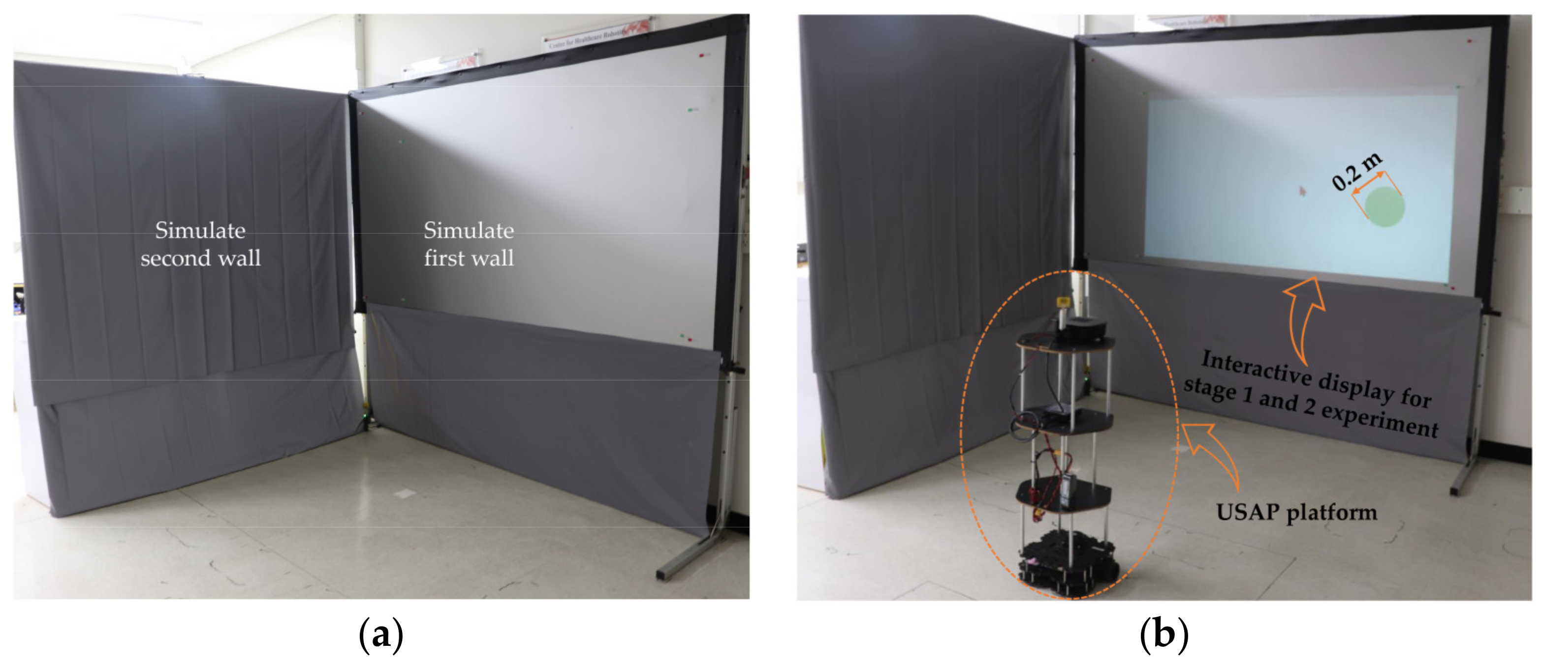
Figure 4. The tracking accuracy given by the UWB sensor’s manufacturer was +/−0.1 m laterally and about +/−0.2 m vertically, where we set the position information update rate to 20 Hz. Most of the time, the tracking accuracy values were lower than the upper accuracy limits provided by the UWB sensor’s manufacturer. Our laboratory walls are not suitable for directly projecting images, so we installed two projector screens in the form of an L-shape to simulate two walls with a size of 2.5 × 2.1 m2 for each (Figure 8a). The USAP platform was positioned at different distances from the simulated walls (Figure 8b).

5.2. Stage 1: On the System’s Interaction Accuracy, Interaction Time, and Workload

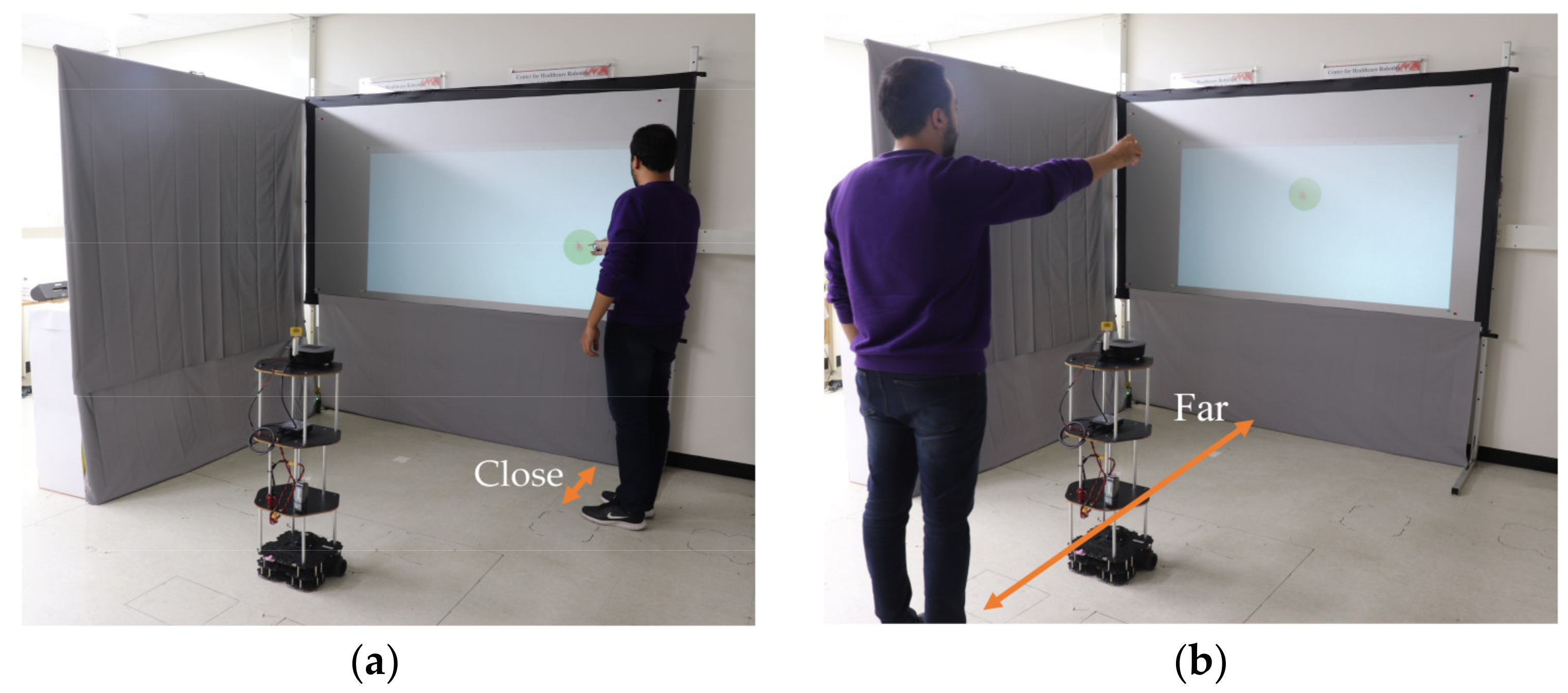
Before starting the main session of Stage 1, each participant had training on using the hand-held input device and experience interacting with the projected screen’s items from varying distances. In the beginning, the USAP platform holds back its position 2 m away opposite to Wall 1 (Figure 8b) while keeping the orientation that placed the projector perpendicular to the horizontal centerline of the same wall. The projected screen was created using Unity software to generate a 2D interactive image of 19 randomly placed circles with a 0.2 m diameter appear on the screen. Each participant was asked to use the input device to click the center of each circle precisely and quickly as much as possible, where visual feedback was given on the user’s hand position in the form of a cursor on the projected screen. One circle stays on display until the participant clicks the input device’s button then a new circle appears in a new location. Participants were asked to stand at different distances opposite to Wall 1. Firstly, they interacted from a close distance by choosing a location between the USAP platform and Wall 1; afterward, they stood behind or beside the USAP platform according to their preference to try the far distance interaction (Figure 9a,b). The participants were free to choose between moving to face the popped-up circle or stretch their hand aside to reach the circle location in both interaction distances. Once the participant had enough experience using our system, we moved forward to the main session.
In the main session, participants tried to reach the randomly popping-up circles and select them by clicking the hand-held input device’s button. Half of the participants start to experience close distance interaction, where the rest of the participants start with far distance interaction. In each case, nineteen circles needed to be reached and selected. Interaction accuracy was calculated when the participant pressed the input device’s button to trigger the target circle. The Euclidian distance was measured by finding the distance between the cursor’s tip and each target circle’s center point positions using Unity engine to measure the interaction accuracy. The calculated Euclidian distance is converted from pixels scale to a meter scale representation using pixels per meter constants (9, 10). Interaction time was also considered as a criterion to evaluate system performance. The elapsed duration between the circle’s appearance and the participant’s selection was measured in seconds to calculate interaction time. Finally, the workload for both interaction distances was measured using the NASA-TLX index [51]; participants were asked to fill out the online survey’s relevant workload parts immediately after they finished each interaction.

5.3. Stage 2: Experience Screen Customization Function and Examine the Influence of UWB-Based Calibration on System Performance

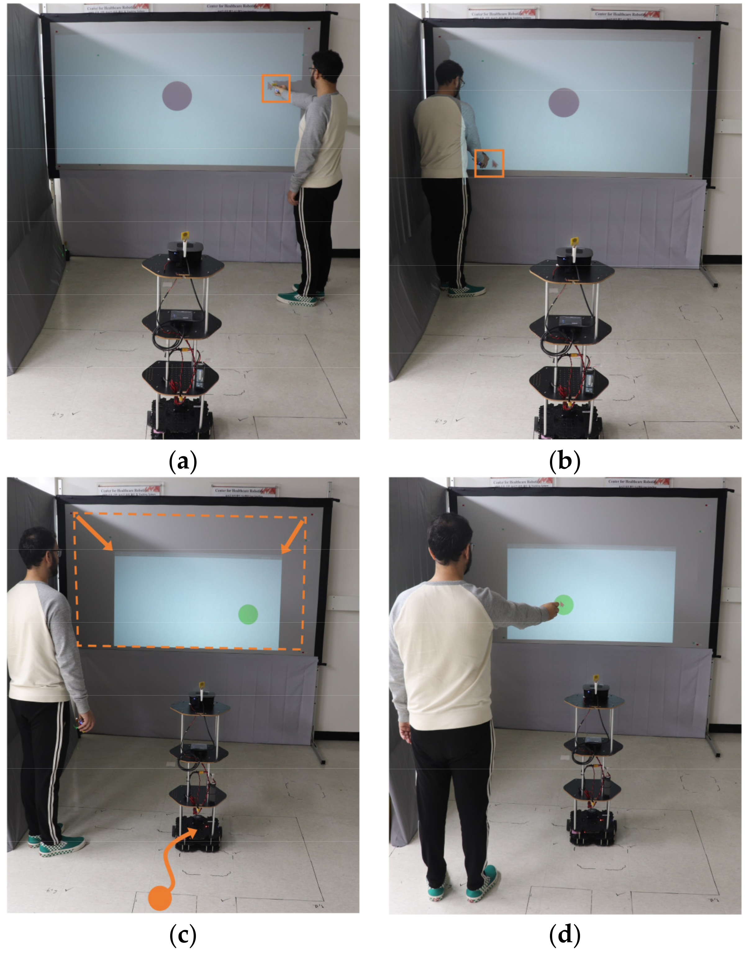
In this stage, customization of the projected screen was tested. Participants designated two diagonal points defining their demanded location and size of the projected screen. In response, the USAP platform moves to deliver the most appropriate display (Figure 10). Subsequently, the participants were asked to perform the same interaction task (to select 19 popped-up circles) as in the first stage. However, participants did this task one time and were free to choose the interaction distance according to their preference. To unify the test condition between the first and the second stages, the popped-up circles kept their 0.2 m diameter by updating their graphical size according to the USAP new position. In the first stage, we defined a pre-calibration measurement for the projection boundaries, as the USAP platform remained static for the entire duration of this stage. Unlike the first stage, the USAP platform was no longer static and was moving around, fulfilling the user’s projection demands. Therefore, the UWB-based calibration algorithm (Section 4.1) needs to be activated. Testing this calibration algorithm’s influence on interaction accuracy, interaction time, and the user’s workload was one of this stage goals, as it is considered key to enabling customized interactions in any location. In the first and the second stages, the success percentage to trigger the popped-up circles was measured, where a false trigger means the participant clicks the input device’s button when the cursor is positioned outside the circle boundaries; in other words, when the interaction accuracy is greater than 0.1 m. Moreover, the undetected triggers were counted to evaluate the efficiency of using our input device for this interaction task. To count these missed triggers, the experimenter asked the participants to inform whenever the projected content does not update (circle does not appear in a new location) after they perform a clicking action.
Evaluating the screen customization process requires answering the following questions: How accurate is the actual customized screen relative to the user’s desired input screen? How accurately can the USAP platform navigate to the target point to customize the projection? How fast can the USAP navigate from the start to the target point? To answer these questions, we stored the participants’ desired input screen dimensions (using the user’s input diagonal points) and compared the virtual screen with the actual screen we obtained after the USAP platform navigated to the target point. Interactions were performed on S1, where the user could define the projected screen over the X-Y plane and the USAP platform navigated within the X-Z plane, as it has a constant height on the Y-axis. Additionally, we stored the navigation path for the USAP platform and recorded the trip duration to the target 2D position.
By the end of Stage 2, participants were asked to share their thoughts about the importance of the projected screen’s customization feature using a 10-point Likert scale question.

5.4. Stage 3: On the Evaluation of the Hand-Held Input Device Interaction Features

In Stage 3, we evaluated other interactive features of the hand-held input device. As discussed before, the input device was equipped with a UWB tag to track the user’s hand movements and a push-button to trigger the selection. In the first and second stages, we used the input device to select the popped-up circles and evaluate various interaction performance aspects. In addition, our customized device could also perform a mid-air drag-and-drop task for a target item (Section 7.4), and it enables the user to perform basic UWB-based mid-air swiping gestures (Section 4.3) for a particular interaction purpose. Drag and drop interaction shares the same mechanism as the normal triggering task in the first and second stages. However, the swiping gestures interaction has a different implementation technique; therefore, we need to evaluate this interaction channel’s performance.
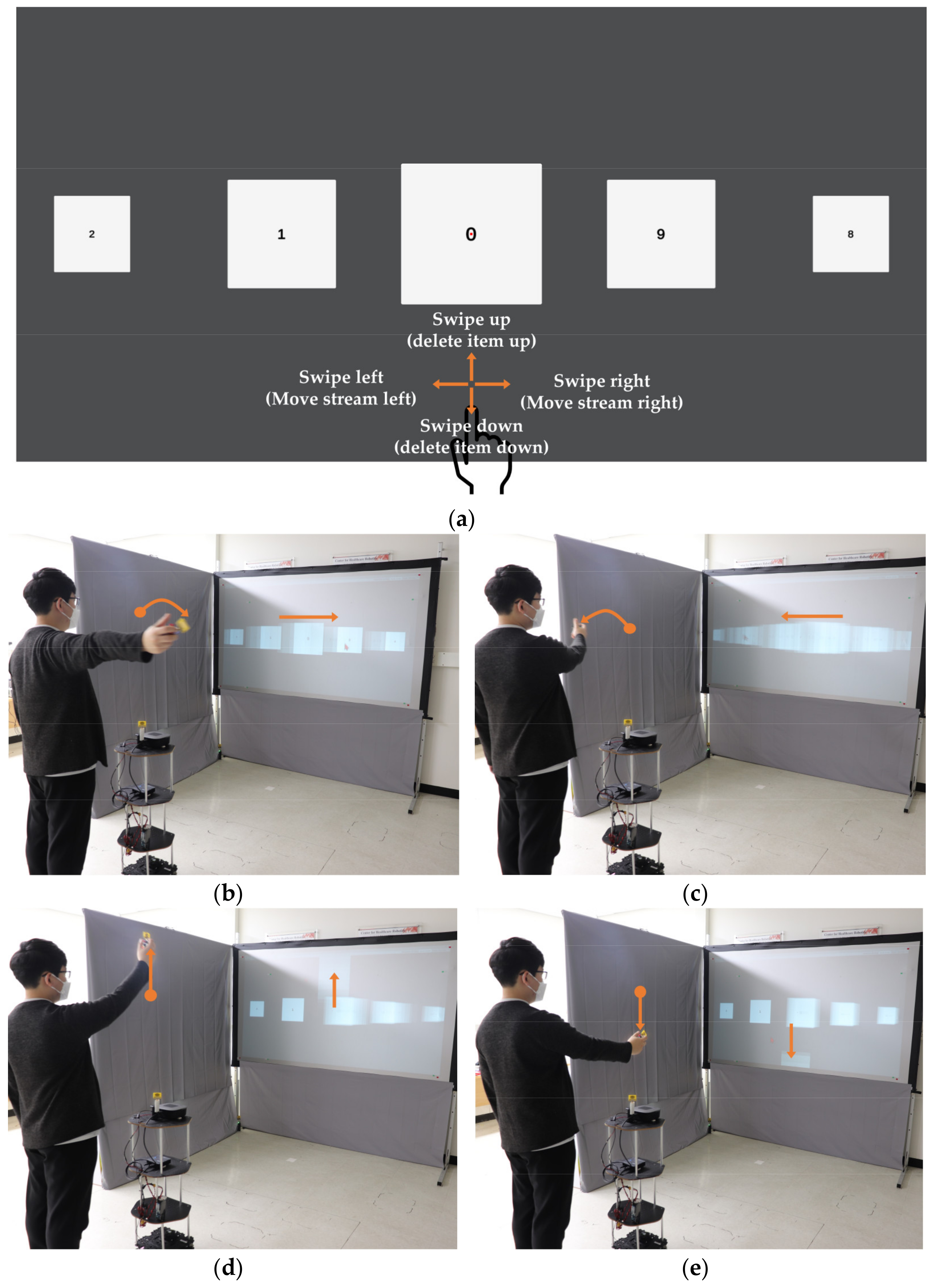
Participants started the third stage learning how to perform swipe gestures in four directions (right, left, up, and down) using the input device. Corresponding to their swipe gestures, they could perceive the motion of a stream of numbered blocks designed by the Unity engine (Figure 11a). The numbered blocks shifted right or left when a participant swipe their hands right or left, respectively. The participant could delete the central block up or down by swiping up or down.
After participants feel familiar with using our device to perform swiping gesture-related interactions, we move forward to the evaluation part. In this stage, we measured the swipe gestures detection accuracy by counting missed or wrong swipes. Missed swipe means that the participant made a swipe gesture in a specific direction, but it does not reflect any movement in the numbered blocks stream. The wrong swipe refers to an uncorrelated movement in the numbered stream (e.g., the participant performs a right swipe action, and the numbered stream shifts left). Also, we check the workload amount when doing UWB-based mid-air swiping tasks. To assess the interaction performance, the experimenter asked each participant to perform four tasks using the input device (Figure 11b–e):
  • Bring the block with the number 5 to the screen’s center by swiping right.
  • Bring the block with the number 9 to the screen’s center by swiping left.
  • Bring the block with the number 7 to the screen’s center by swiping right and then delete it by swiping up.
  • Bring the block with the number 2 to the screen’s center by swiping left and then delete it by swiping down.
Eighteen swipe gestures are the total number of swipes each participant supposed to do when following the previous four steps without encountering any problem. The experimenter monitored each participant’s performance and asked them to report any wrong or missed swipe to calculate the swipe gestures interaction accuracy. Both missed and wrong swipes represent an unwanted performance of UWB-based swipe gesture detection.
Additionally, participants were asked to assess their workload when performing swipe tasks through the online survey and answer a 10-point Likert scale questioner to understand how they think about the importance of adding these swipe gestures interactive features.

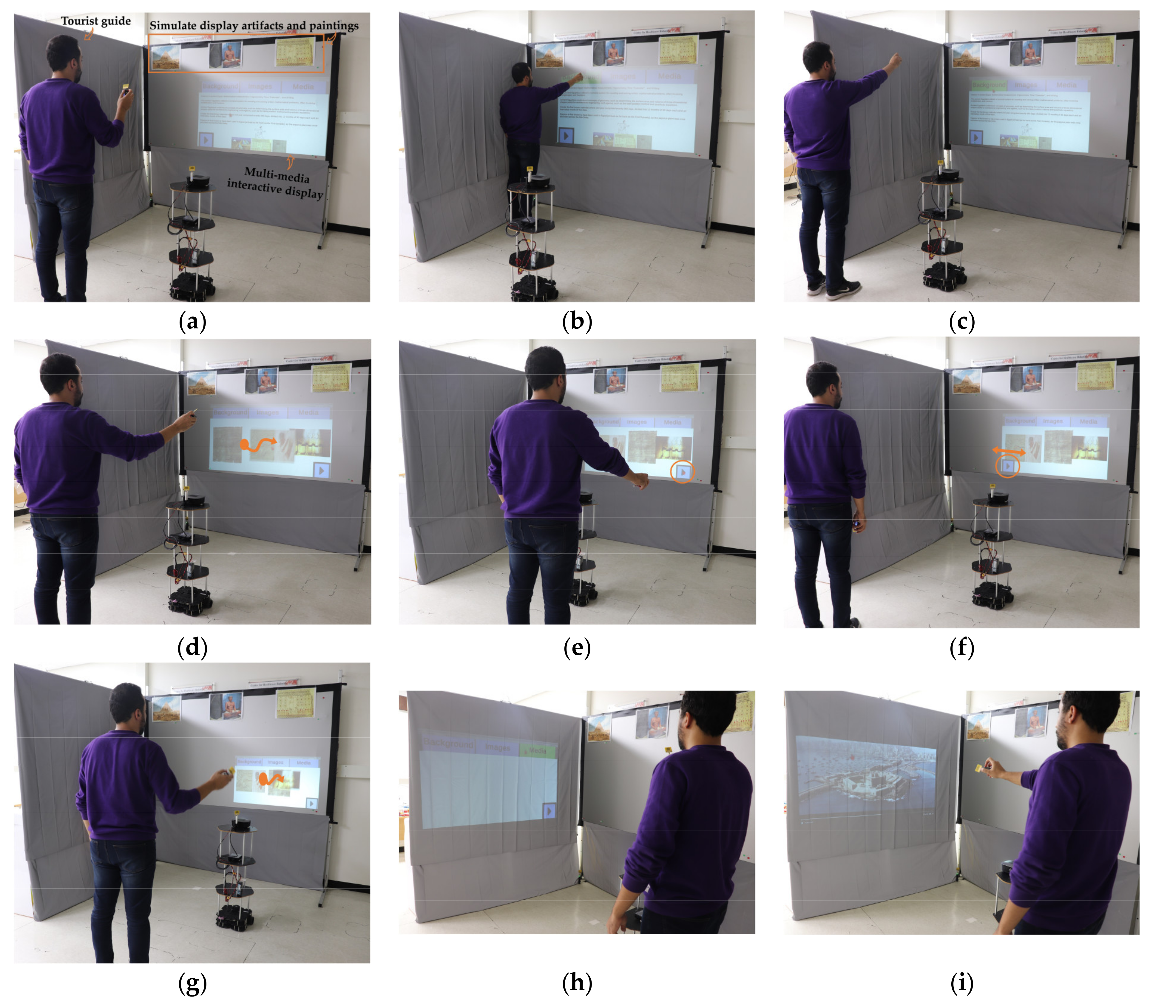
5.5. Stage 4: Evaluation of System Usability

Even though participants experienced our system throughout previous stages and read about different system components in the online survey introduction, they did not have detailed knowledge on how this technology can be used, i.e., in which practical contexts the USAP platform could be employed. Therefore, it was essential to reveal a possible utility or application of our system that participants could understand. In the fourth stage, participants were asked to watch a video showing our system’s usage in a museum-simulated environment (Section 7.4). Participants were then asked to fill out a System Usability Scale (SUS) using the online survey to evaluate the system’s overall usability based on their practical experience during all prior stages and the knowledge they obtained from watching the demonstration video. Using a video-based survey is a common method of evaluating system performance [52], especially when participants cannot use all system features themselves because they are not in a certain location or experimental limitations in terms of time or physical fatigue.

6. Results

To test the interaction accuracy and interaction time across various interaction cases, the collected data were subjected to one-way repeated measures ANOVA tests for post-hoc tests at a 5% confidence level. Equivalence tests were performed to analyze pairwise comparisons (Bonferroni-corrected or Games-Howell-corrected as post-hoc tests after checking the homogeneity of variances). Also, we used the independent samples Kruskal–Wallis H test as a non-parametric test to analyze the participants’ workload data across various interaction cases.
The correct selections of popped-up circles were counted for each interaction case to determine the success hit percentage in Stage 1 and Stage 2. To assess the performance of customizing the projected screen, the accuracy error between the participants’ desired screen and the actual customized screen was calculated. Additionally, the navigation accuracy and time of the USAP platform were presented. In Stage 3, the success percentage rate was calculated to evaluate the hand-held device’s swiping accuracy. Finally, in Stage 4, the system usability scale was examined to evaluate the overall usability of our proposed system.

6.1. Triggering Task Interaction Performance

In Stage 1 and 2 participants interacted with our system using three different interaction cases: Close interaction with fixed pre-calibration measurements (close interaction), far interaction with fixed pre-calibration measurements (far interaction), and free distance interaction with activating the UWB-based calibration (active calibration interaction). Participant’s interaction accuracy, interaction time, and workload were calculated for each interaction case to investigate the influence of the interaction distances and the active UWB-based calibration on the participants’ interaction performance. It is essential to mention that fourteen out of sixteen participants prefer interacting from a far distance during the active calibration interaction case.

6.1.1. Interaction Accuracy

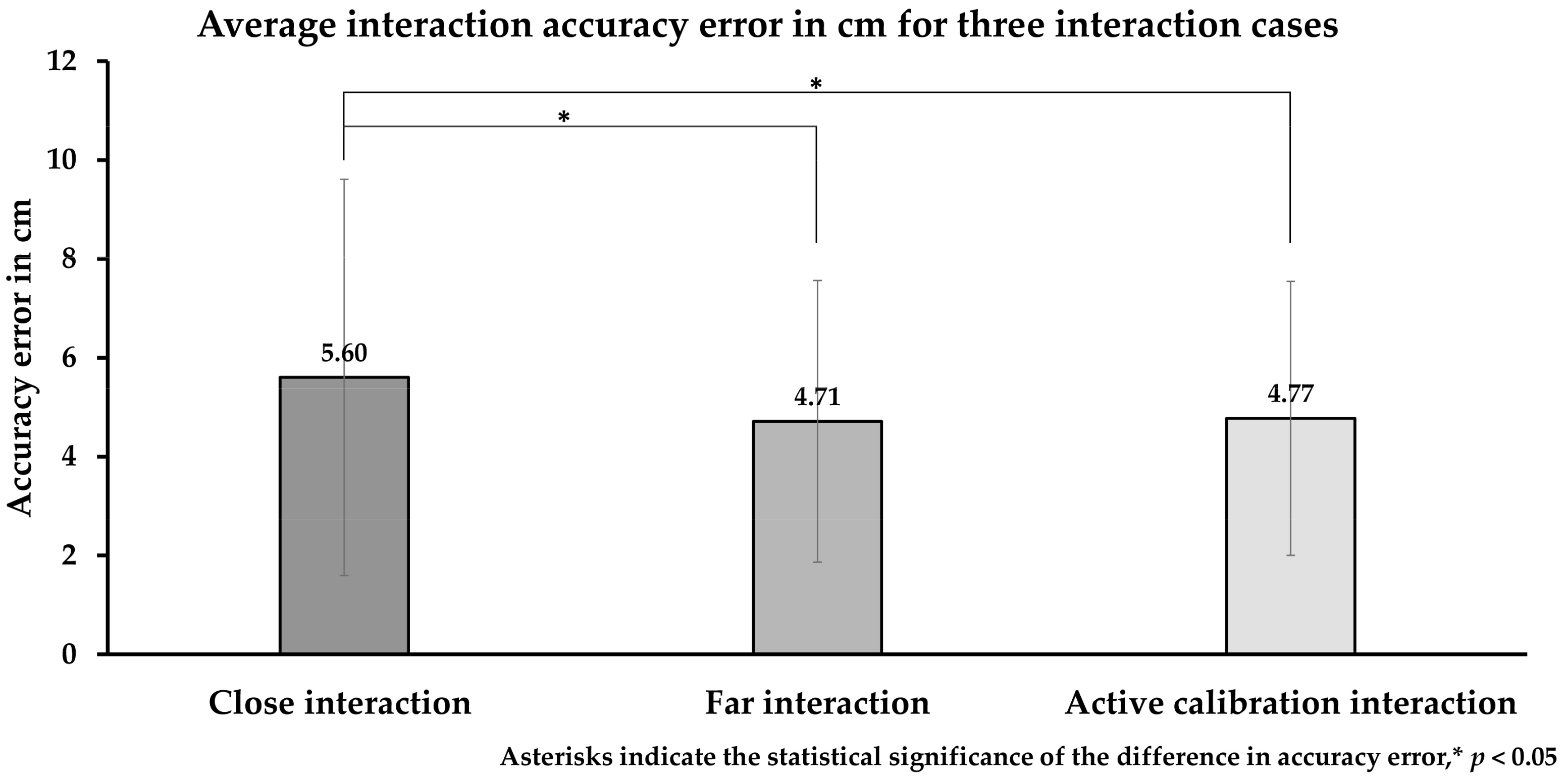
We analyzed the average interaction accuracy for each interaction case across Stage 1 and 2. We found that interaction distance significantly influences interaction accuracy, where participants achieve better interaction accuracy when interacting from a far distance. On the other hand, the UWB-based calibration algorithm performs almost the same as fixed pre-calibration measurement, indicating high efficiency while using this algorithm for mobile interactive scenarios.
The one-way repeated measure ANOVA test shows an overall significant difference between the three interaction cases (close, far, and active calibration); F (2, 30) = 4.22, p = 0.024. The interaction accuracy error in the case of close interaction (M = 5.60, SD = 1.21) was significantly higher than the active calibration interaction (M = 4.77, SD = 1.15, p = 0.037) and the far interaction (M = 4.71, SD = 1.06, p = 0.023) cases. There were no significant differences in the interaction accuracy error between far and active calibration interaction cases (Figure 12).
The success percentage rate (where participants successfully click inside the circle boundaries) was 90.46% for close interactions, 95.07% for far interactions, and 96.6% for active calibration interaction cases.

6.1.2. Interaction Time

The average interaction time were measured for each interaction case across Stage 1 and 2. Similarly, far distance interaction reduces the interaction time significantly, where the UWB-based calibration algorithm does not influence the interaction time.
The repeated measure ANOVA test shows a significant difference between the three interaction cases (close, far, and active calibration); F (2, 30) = 6.51, p = 0.005. The active calibration interaction case had the fastest interaction time (M = 2.83, SD = 0.87, p = 0.02), followed by the far interaction (M = 2.84, SD = 0.65, p = 0.010) and close interaction (M = 3.79, SD = 1.29) cases, as shown in Figure 13. The interaction time of the close interaction case was significantly greater than the interaction time of the active calibration interaction (p = 0.02) and the far interaction (p = 0.010) cases. There were no significant differences in interaction time between the far and active calibration interaction cases.
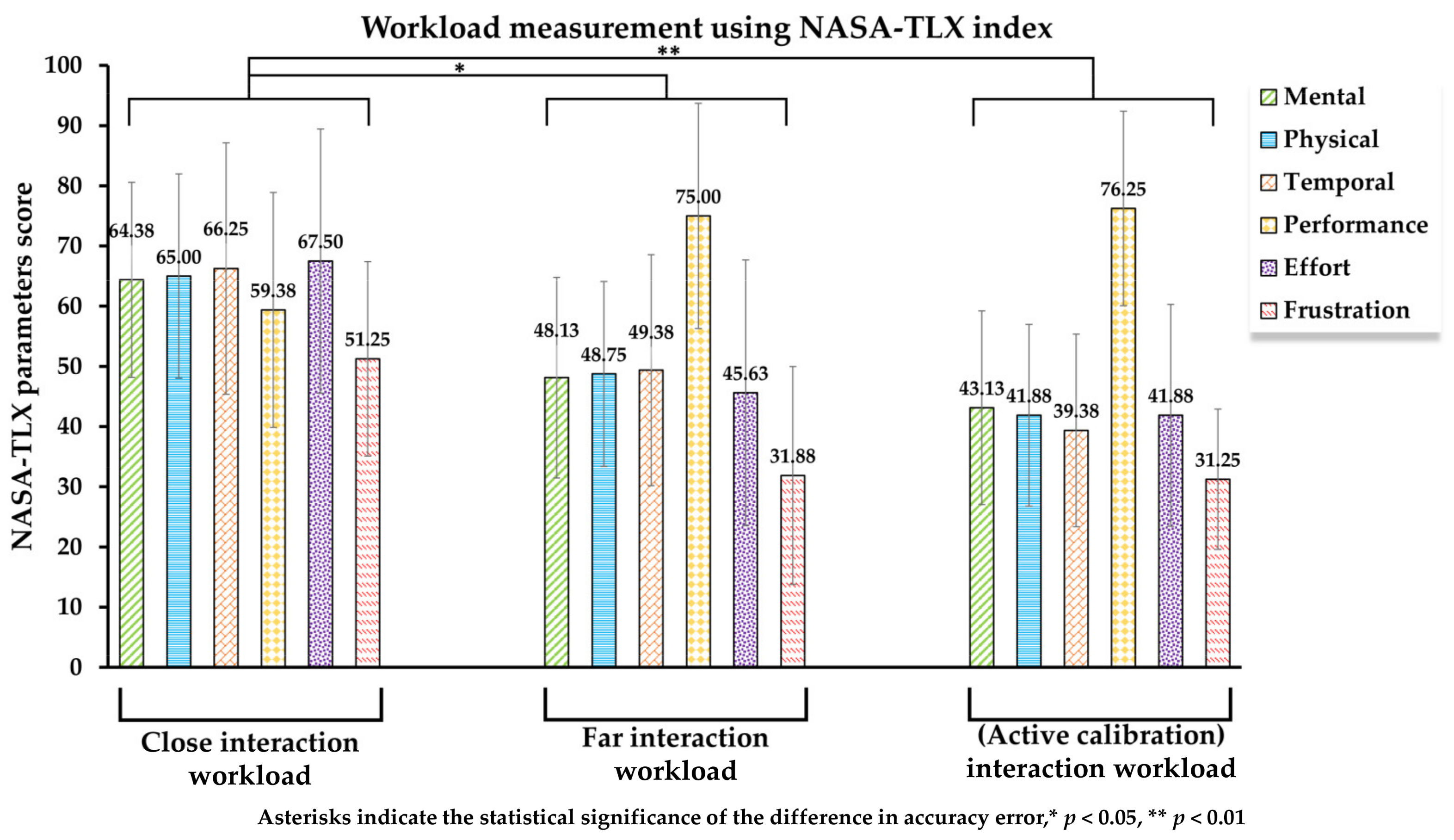
6.1.3. Workload

We measured the average workload for each interaction case across Stage 1 and 2. To determine an overall workload rating, the subjective workload was measured by the NASA Task Load Index (NASA-TLX). NASA-TLX derives an overall workload score based on six dimensions (mental demand, physical demand, temporal demand, effort, performance, and frustration). Each dimension is evaluated on a scale of 0 to 100 [51]. Interacting from a far distance causes a significantly lesser workload consistent with previous results where participants experience more accurate and faster interaction when performing far interaction. Moreover, fixed or active calibration does not influence the interaction workload.
The Independent-Samples Kruskal–Wallis H test shows a significant difference in overall workload in the NASA-TLX: H (2) = 14.32, p = 0.001. The close interaction case (M = 59.17, SD = 15.04) scored significantly higher workload than the far interaction cases (M = 41.46, SD = 14.13, p = 0.011) and the active calibration interaction cases (M = 36.88, SD = 12.76, p = 0.001). There were no significant differences in workload between the far and active calibration interaction cases, as shown in Figure 14.

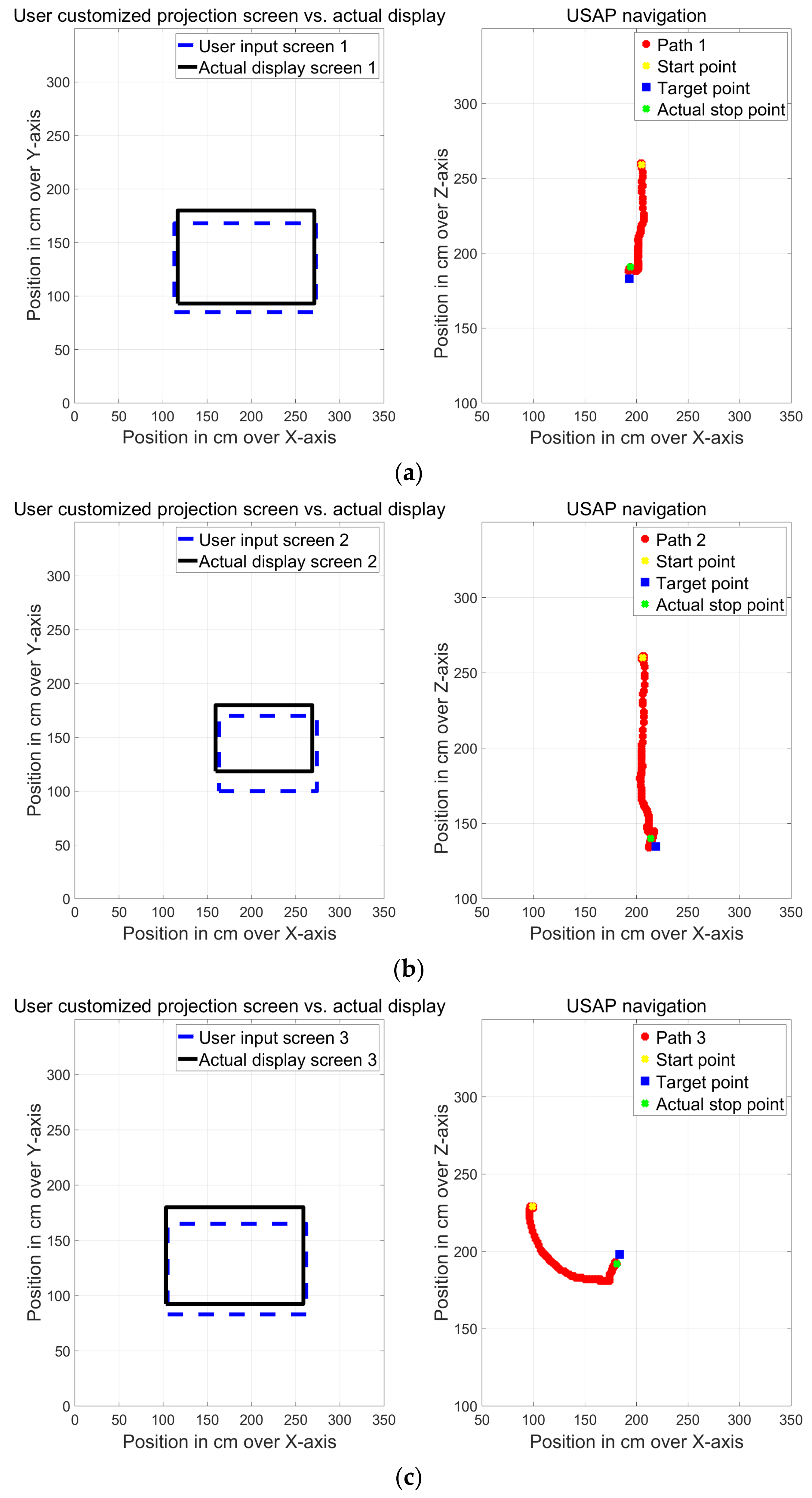
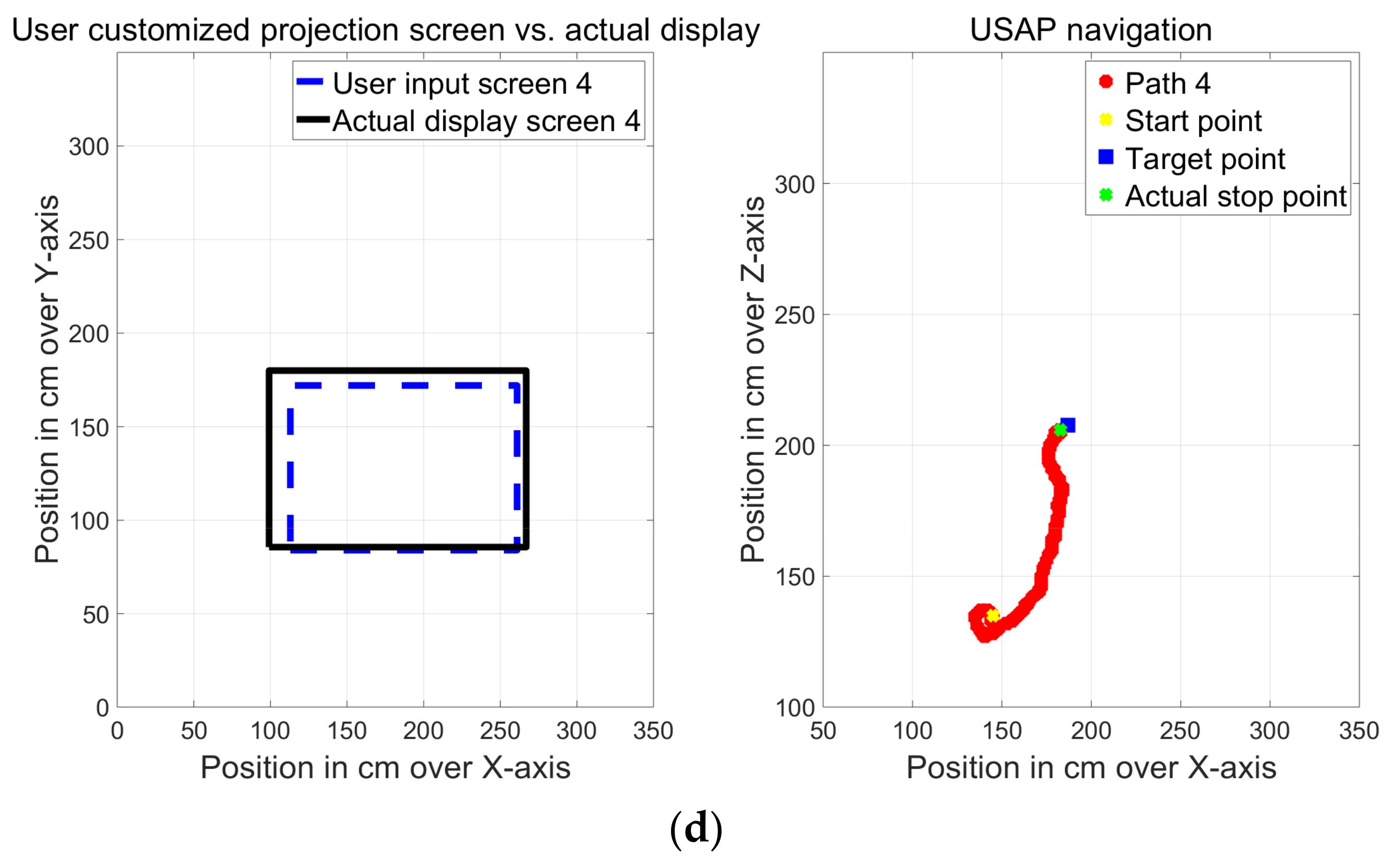
6.2. Screen Customization Performance and USAP Navigation

We stored the UWB positioning data of users’ hand activities and USAP navigation path to assess screen customization performance. Participants designated diagonal points to customize the projected screen had saved to draw the desired virtual input screen in (dotted blue), where the actual projected screen that created after the USAP platform stops movement drawn in (solid black) as shown in Figure 15. Four examples, Figure 15 left part, showing different trials in which four screens were customized with different sizes and locations. Comparing the two-screen tells about the accuracy level on how the user can customize the projected screen and how technically the USAP platform meets the user demand. We found that the USAP platform delivers the nearest possible customized screen to the user’s input, where the average displacement between the participant’s virtual input screen (dotted blue) and the actual projected screen (solid black) was 0.049 m on the X-axis and 0.135 m on the Y-axis.
After assigning the designated diagonal points for the desired customized screen, the central server finds the target coordinates where the USAP platform should navigate (Section 4.2). Tracking the USAP platform position, we can determine the navigation accuracy from the target point as described in Figure 15 right part. We found the navigation accuracy shows acceptable values that can support the demanded AR applications requirement. The USAP platform started navigating from different locations to meet the participants’ desired screen location and achieved a 0.12 m average distance accuracy from the target point. The USAP navigated within a relatively small area of 1 × 1 m2 and took 10.4 s average time to reach the target point, including the time to adjust its heading.
Most participants (82.51%) thought that adding the feature of customizing the projected screen is important.

6.3. UWB-Based Mid-Air Triggering and Swipe Gestures Detection

We counted the missed triggers in the first two stages to evaluate the input device’s selection performance. Out of 912 triggering actions, we recorded 11 missed triggers with a success rate of 98.79%. Similarly, in the third stage we measured the success rate of swiping tasks to evaluate the UWB-based mid-air swipe gesture detection as one of the interaction channels to manipulate the augmented graphics. A high success detection percentage of 98.26% has been achieved with five missed or wrong swipes overall. While performing the swiping task, the workload was numerically the lowest compared to the workload values when doing other interaction tasks in previous stages, where NASA-TLX index scored (M = 35.41, SD = 17.76). Lastly, most participants (84.38%) thought that the swiping feature was important for interacting with projected content.

6.4. System Usability

We assessed the participants’ subjective usability using the system usability scale (SUS) for the overall system performance. SUS is a scale of 0 to 100 with increments of 10 and ranges from “Strongly Disagree” to “Strongly Agree”. SUS scores > 71 points indicate that the system is acceptable [53]. The results of our system usability test were (M = 77.83, SD = 13.63), which indicates that our system was acceptable for the user.

7. Discussion and Candidate Applications

7.1. Influence of the Interaction Distance on Interaction Accuracy, Interaction Time, and Workload

Regarding the first stage, we noticed that increasing the interaction distance decreased the interaction error and time significantly (Figure 12 and Figure 13). When participants were asked to interact closely, they were 0.3–0.7 m from the wall, mainly to avoid blocking the projector-beam with their body. Most participants stood behind the USAP platform for far interactions and were 0.2–0.5 m away from it. The majority of participants interacted faster and more accurately when interacting from a far distance because they could see the full projected screen without colliding the screen with their body or arms. As shown in Figure 14, participants’ lower workload was achieved when interacting from a far distance. Even though a close interaction with the USAP platform is possible, participants did not prefer it because of the projector’s beam blockage problem. Despite the freedom given to the participants to select the interaction distance inside the coverage envelope of the UWB wireless sensor network, the maximum distance they selected for interaction was 2.7 m from the projected screen. According to the room dimensions, participants can stand away up to 7 m from the projected screen. However, they selected a shorter interaction distance which provides the best visual feedback. To validate our design and test it under the maximum limit, we tried to interact with the projected screen over S1 from the maximum possible distance, and we found the interaction accuracy under 0.1 m matches the results shown in Figure 12.
Systems that convert surrounding spaces to support interactive applications like Wall++ [42] and IBM’s Everywhere Display [6] face the problem where far distance interaction with a projected content is either less accurate or impossible. Our system allows us to interact with the projected content from both close and far distances with a fair interaction accuracy. Moreover, it affords the user the ability to customize the projected screen on a relatively large space indoors. In general, regardless of the interaction distance, our system gives more freedom of movement for the user as it is not restricting the interaction place or define a specific range to remain able to interact.

7.2. The UWB-Based Calibration Influence on Interaction Performance

The UWB-based calibration algorithm is the core part of our implementation to interact with the projected screen at any defined location. Checking its influence on the interaction performance is essential to guarantee its efficiency to calibrate the projected screens’ location dynamically. During Stage 2, 14 out of the 16 participants chose to perform the interaction task from a far distance, and most of them commented that “it is more convenient and allows for a faster and easier interaction experience”. Figure 12, Figure 13 and Figure 14 show no significant difference in the interaction performance when using a fixed and pre-calibration measurement in Stage 1 to interact from a far distance and when activate the UWB-based calibration algorithm in Stage 2. Therefore, system performance using UWB-based calibration is the same or even numerically better than using a pre-calibration measurement for a static position. That shows our proposed UWB-based calibration algorithm’s effectiveness to enable the interaction after any movement of the USAP platform. On the other hand, interaction accuracy error, interaction time, and workload when activating the UWB-based calibration algorithm are significantly lower than those of the close interaction case. This is not due to the calibration algorithm; it is because most of the users prefer to interact from a far distance in the Stag 2. Therefore, our calibration algorithm has no direct influence on the interaction performance.

7.3. Projected Screen Customization and USAP Platform Navigation Performance

Participants considered the customization technique itself to be an important part of the projection process. As they have the freedom to select any interactive surface and define the location and size of the projected screen. All participants rated this feature highly, as they considered it a promising feature for SAPs.
The USAP as a mobile platform achieves a reasonable navigation accuracy, with a 0.12 m average accuracy error from the target point (Figure 15). This accuracy error is considered acceptable, as the USAP performs navigation under a UWB wireless sensor network coverage, which supports accuracy of +/−0.1 m laterally and about +/−0.2 m vertically. The navigation time between two points in a 1 × 1 m2 area was slow, with an average time of 10.4 s. The USAP was built on Turtlebot3 waffle pi, which is a relatively slow-speed mobile platform. We recognize this mobile platform as a tool to prove our main concept, thus Turtlebot3 waffle pi could be replaced with a faster, omnidirectional mobile robot for further enhancement.
The customization performance of the projected screen has been evaluated (Figure 15). An acceptable error margin between the user’s desired input screen and the actual displayed screen was shown, with an average displacement error of 0.049 m on the X-axis and 0.135 m on the Y-axis. A better performance was shown over the X-axis, as the USAP platform could be controlled to manipulate the display on the X-axis direction by performing horizontal displacement (consider the projection over S1). A lower accuracy was presented on the Y-axis because of the limited ability to control beam pitching. Our projector shows a 100% offset for the projected beam with a fixed aspect ratio of 16:9, i.e., it fixes the lower limit of the projected window at a fixed height for all projection cases. Even though participants want to push the projected screen upwards (Figure 15b), these technical limitations oppose. It means that the projected screen height is tuned automatically according to the user’s defined screen width. Therefore, the USAP platform delivers the best match to the user’s desired screen under current technical restrictions. A better match could be achieved considering further technical enhancements; however, the current performance is satisfying to verify our proposed concept.

7.4. UWB-Based Hand-Held Input Device Performance

The hand-held input device was used in the first and second stages for selecting popped-up circles and in the third stage to manipulate the projected items using UWB-based mid-air swipe gestures. For the selection task, the input device shows high reliability, with a success rate of 98.79%, where its trigger action missed to be detected 11 times out of 912 triggering trials. The success rate was 98.26% for swiping task, with five wrong or missed swipes from 288 swiping trials. The workload of swiping tasks was lower than that of the selection task without any significant differences, where in general, using our customized device for these interaction tasks creates a moderate workload. Overall, the customized hand-held device could be used as a remote, multi-functional, interaction input device. The hand-held device fits an adult palm-size, and the interaction button lies under the user’s index finger or thumb, according to their preference (Figure 2b). This design guarantees a comfortable grip and a smooth interaction experience.

7.5. Overall System Abilities and Candidate Applications

To our knowledge, we are the first to use the UWB positioning system to enable the interaction with projection-based augmented content over a dynamically changing user-defined projection screen at room-scale. Our proposed system delivers a comparable interaction accuracy to the state-of-the-art systems in this field [37,42]. We can achieve an interaction accuracy lower than 0.1 m in most interaction cases. Different conventional systems confine the user interaction area to achieve the best interaction accuracy [33,39], where our system improves the user’s ability to define their best interaction distance. The user is fully involved in the projection process to customize the projected screen’s size and location; on the other hand, several systems remove this facility from the user by restricting the interaction area to a specific location and size due to the pre-setup requirements [10,15]. Some conventional projection-based interactive AR systems cannot serve for applications that demand extended indoor interactive spaces, flexible assigning for the interactive areas, and larger user’s interactive envelope [20,21,22]. Nevertheless, thanks to our system’s mobility and customization capability, normal indoor spaces can support diverse interactive tasks. Extended indoor interactive spaces demand various interactive content generation. The USAP platform’s awareness of its position and orientation automatically generates the suited interactive content for distinct interactive locations. Unlike systems that use a heavy processing unit to calibrate for the projected screens [36,41], our light-computational UWB-based calibration algorithm can run even in a small microcontroller processor. Not only light-computational power but also efficient calibration performance can be achieved; our algorithm shows a similar performance to static calibration conditions when calibrating for the projected screen whenever the USAP platform navigates to meet projection requirements. The high success rate to perform mid-air interaction tasks (98.79% for selecting and 98.26% for swiping) shows the reliability of using our hand-held input device. The relatively low workload values when using hands to perform spatial projection-based interaction and the system usability score (M = 77.83) reflects our system’s intimate design compare to similar functioning systems [39].
Therefore, our system abilities suit the museum environment, including large or several exhibition halls, where interactive multimedia displays are demanded in various locations indoors. To expose what this system can do, we simulated a museum environment using the same setup, as shown in Figure 8. The USAP platform could augment a display working as explanatory interactive content for artifacts shown physically inside an exhibition hall (Figure 16a). The user could be conceived as a tourist guide that can perform interactions from different distances with the projected screens (Figure 16b,c). The projected screen’s size and location could be selected to provide more information about a specific artifact. The input device’s pointing accuracy enables the user to illustrate a specific graphical item (Figure 16e). Drag and drop projected items are also possible for interactive demonstration purposes or designing interactive games if demanded (Figure 16d). For better controllability, the graphical control buttons could follow the user’s position to make them reachable whenever they want to use them (Figure 16f). Customizing the projected screen is not confined to bigger-sized screens; however, the user could continue interacting with a relatively small screen (1 m diameter) (Figure 16g). Since UWB wireless network can turn the room’s surfaces to support interactive applications, therefore, same interaction capabilities over the first simulated wall could be performed over the second simulated wall (Figure 16h). The user can play a video as a supportive media and control its operation (play/pause) using the input device (Figure 16i). The UWB-based calibration algorithm should run continuously in the background, so performing all these interactive features is possible. This simulated use of our system in a museum environment was shown to all participants as a demonstration video [54] in our experiment’s Stage 4.
As noted, this study’s main interest was to create an intuitive interaction environment for the dynamically changing indoor spaces where interactivity with surroundings is demanded in several locations. Our proposed methodology and practical implementation were focused on raising the interaction ability giving the user privileges to customize and control the interaction process. Even though enhancing the interactivity for indoor spaces is essential, safety concerns must be considered. Using USAP as a mobile platform raises safety concerns like the protection level to navigate the USAP with visitors moving around and the possibility of hurting visitors’ eyes if they block the projection beam. Conceptually we will present two methods as possible candidates to tackle most of the safety issues and consider testing them practically as a further enhancement for our study. The first method is to create a physical blockage between the USAP platform and people; then, the mobile platform can navigate in a wide enough and constrained area to deliver the interactive display. This solution is practically simple, but it could restrict visitors’ movement near on-display items and add some limitations to the interaction process (Figure 17a). The second method (Figure 17b) using matured collision avoidance techniques to avoid dangerous contact with visitors, along with adding an audio feedback warning feature to ask users not to approach the projector’s throw field using onboard proximity sensing or image processing techniques.

8. Limitations and Future Work

Our study has evaluated the interaction performance considering various aspects using a prototype-level mobile platform and input device. However, upgrading hardware is recommended, especially with the USAP platform, to support faster and heavy-duty navigation tasks. The symmetrical structure to install and use the UWB wireless network leads to perform the interaction tasks in multi-rooms similar to single room implementation. Nevertheless, we aim to extend the setup and test it for different interactive spaces as future work. The current implementation illustrates a straightforward mechanism to switch between different walls performing interactions; however, manual rotation for the projector is required to initiate floor and ceiling interaction. Therefore, a commercially available tilting mechanism is going to be added to automate this task. Lastly, through the fusion of a 9-DOF inertial measurement unit (IMU) and UWB position information, we could enhance the stability and the accuracy of the interaction experience; also, more intuitive methods of defining the interaction surface could be achieved.

9. Conclusions

This study proposes a novel UWB-driven self-actuated projector platform that supports accurate, mobile, and user-friendly interactive projection-based AR applications. Our system deployed a UWB wireless sensor network to perform 3D position tracking. That further facilitates a surrounding interactive exposure and expands the interaction experience beyond a fixed location’s limits. Alongside expanding the interactive area, the user can choose the most appropriate distance to interact with the projected screen unconfined by any physical restrictions. We developed a light-computation UWB-based calibration algorithm, which is considered the heart of our design, to enable all other system features. We tested various performance aspects of this system in a simulated museum environment, which show high adaption to vast and dynamically changing interactive environments. Using our system, the user can manipulate and customize the augmented screens’ properties at any location inside the coverage area of the UWB wireless sensor network. Intuitive and highly reliable mid-air interactive functions could be performed using our designed hand-held device for remote pointing, selecting, dragging and dropping, and swiping. The experimental results illustrated that the proposed system accomplishes a moderate accuracy and a relatively low workload while assigning the interactive screen and interacting with the augmented content. Overall, the designed prototype provides a promising practical solution to perform versatile indoor interactive spatial projection activities and permits further development to achieve more enhanced results.

Author Contributions

Conceptualization, methodology, and formal analysis, A.E.; software, A.E., D.K., and K.N.; writing—original draft, A.E., K.N., and D.K.; writing—review and editing, A.E., K.N., D.K., and M.S.K.; supervision, M.S.K. All authors have read and agreed to the published version of the manuscript.

Funding

This research is supported by the Ministry of Culture, Sports, and Tourism (MCST) and Korea Creative Content Agency (KOCCA) in the Culture Technology (CT) Research & Development Program 2020 (GM13510).

Data Availability Statement

The data presented in this study are available from the corresponding author upon reasonable request.

Conflicts of Interest

The authors declare that there is no conflict of interest.

References

  1. Streitz, N.A. From human–computer interaction to human–environment interaction: Ambient intelligence and the disappearing computer. In Proceedings of the 9th ERCIM Workshop on User Interfaces for All, Königswinter, Germany, 27–28 September 2006; pp. 3–13. [Google Scholar]
  2. Müller, J.; Alt, F.; Michelis, D.; Schmidt, A. Requirements and design space for interactive public displays. In Proceedings of the 18th ACM international Conference on Multimedia, Firenze, Italy, 25–27 October 2010; pp. 1285–1294. [Google Scholar]
  3. Bimber, O.; Raskar, R. Spatial Augmented Reality: Merging Real and Virtual Worlds, 1st ed.; Peters, A.K., Ed.; CRC Press: New York, NY, USA, 2005. [Google Scholar]
  4. Interactive Classroom Projectors. Available online: https://www.benq.com/en-ap/business/projector/interactive-classroom-projectors.html (accessed on 4 January 2021).
  5. Li, J.; Greenberg, S.; Sharlin, E.; Jorge, J. Interactive two-sided transparent displays: Designing for collaboration. In Proceedings of the 2014 Conference on Designing Interactive Systems, Vancouver BC, Canada, 21–25 June 2014; pp. 395–404. [Google Scholar]
  6. Pinhanez, C. Using a steerable projector and a camera to transform surfaces into interactive displays. In Proceedings of the CHI’01 Extended Abstracts on Human Factors in Computing Systems, Seattle, DA, USA, 31 March–5 April 2001; pp. 369–370. [Google Scholar]
  7. Wilson, A.; Benko, H.; Izadi, S.; Hilliges, O. Steerable augmented reality with the beamatron. In Proceedings of the 25th Annual ACM Symposium on User Interface Software and Technology, Cambridge, MS, USA, 7–10 October 2012; pp. 413–422. [Google Scholar]
  8. Byun, J.; Han, T.D. PPAP: Perspective projection augment platform with pan–tilt actuation for improved spatial perception. Sensors 2019, 19, 2652. [Google Scholar] [CrossRef] [PubMed] [Green Version]
  9. Schmidt, S.; Steinicke, F.; Irlitti, A.; Thomas, B.H. Floor-projected guidance cues for collaborative exploration of spatial augmented reality setups. In Proceedings of the 2018 ACM International Conference on Interactive Surfaces and Spaces, Tokyo, Japan, 25–28 November 2018; pp. 279–289. [Google Scholar]
  10. Fender, A.R.; Benko, H.; Wilson, A. Meetalive: Room-scale omni-directional display system for multi-user content and control sharing. In Proceedings of the 2017 ACM International Conference on Interactive Surfaces and Spaces, Brighton, UK, 17–20 October 2017; pp. 106–115. [Google Scholar]
  11. Keil, J.; Korte, A.; Ratmer, A.; Edler, D.; Dickmann, F. Augmented reality (AR) and spatial cognition: Effects of holographic grids on distance estimation and location memory in a 3d indoor scenario. PFG J. Photogramm. Remote Sens. Geoinform. Sci. 2020, 88, 165–172. [Google Scholar] [CrossRef]
  12. Kwiatek, C.; Sharif, M.; Li, S.; Haas, C.; Walbridge, S. Impact of augmented reality and spatial cognition on assembly in construction. Autom. Construct. 2019, 108, 102935. [Google Scholar] [CrossRef]
  13. Hakvoort, G. The immersive museum. In Proceedings of the 2013 ACM International Conference on Interactive Tabletops and Surfaces, St. Andrews, UK, 6–9 October 2013; pp. 463–468. [Google Scholar]
  14. Park, J. Examining the Impact of Immersive Technology Display on Exhibition Attendees’ Satisfaction. Ph.D. Thesis, California State Polytechnic University, Pomona, CA, USA, 17 June 2020. [Google Scholar]
  15. Marton, F.; Rodriguez, M.B.; Bettio, F.; Agus, M.; Villanueva, A.J.; Gobbetti, E. IsoCam: Interactive visual exploration of massive cultural heritage models on large projection setups. JOCCH 2014, 7, 1–24. [Google Scholar] [CrossRef]
  16. Gkiti, C.; Varia, E.; Zikoudi, C.; Kirmanidou, A.; Kyriakati, I.; Vosinakis, S.; Gavalas, D.; Stavrakis, M.; Koutsabasis, P. i-Wall: A low-cost interactive wall for enhancing visitor experience and promoting industrial heritage in museums. In Proceedings of the Euro-Mediterranean Conference, Nicosia, Cyprus, 29 October–3 November 2018; pp. 90–100. [Google Scholar]
  17. Yamazoe, H.; Kasetani, M.; Noguchi, T.; Lee, J.H. Projection mapping onto multiple objects using a projector robot. Adv. Robot. Res. 2018, 2, 45–57. [Google Scholar]
  18. Doshi, A.; Smith, R.T.; Thomas, B.H.; Bouras, C. Use of projector based augmented reality to improve manual spot-welding precision and accuracy for automotive manufacturing. Int. J. Adv. Manuf. Technol. 2017, 89, 1279–1293. [Google Scholar] [CrossRef] [Green Version]
  19. Borrmann, D.; Leutert, F.; Schilling, K.; Nüchter, A. Spatial projection of thermal data for visual inspection. In Proceedings of the 2016 14th International Conference on Control, Automation, Robotics and Vision (ICARCV), Phuket, Thailand, 13–15 November 2016; pp. 1–6. [Google Scholar]
  20. Diesburg, S.M.; Feldhaus, C.A.; Oswald, C.; Boudreau, C.; Brown, B. Evaluating elementary student interaction with ubiquitous touch projection technology. In Proceedings of the 17th ACM Conference on Interaction Design and Children, Trondheim, Norway, 19–22 June 2018; pp. 357–364. [Google Scholar]
  21. Jeong, Y.; Kim, H.J.; Yun, G.; Nam, T.J. WIKA: A projected augmented reality workbench for interactive kinetic art. In Proceedings of the 33rd Annual ACM Symposium on User Interface Software and Technology, Minneapolis, MN, USA, 20–23 October 2020; pp. 999–1009. [Google Scholar]
  22. Hoang, T.; Reinoso, M.; Joukhadar, Z.; Vetere, F.; Kelly, D. Augmented studio: Projection mapping on moving body for physiotherapy education. In Proceedings of the 2017 CHI Conference on Human Factors in Computing Systems, Denver, CO, USA, 6–11 May 2017; pp. 1419–1430. [Google Scholar]
  23. Wolf, K.; Funk, M.; Knierim, P.; Löchtefeld, M. Survey of interactive displays through mobile projections. IJMHCI 2016, 8, 29–41. [Google Scholar] [CrossRef] [Green Version]
  24. Ojer, M.; Alvarez, H.; Serrano, I.; Saiz, F.A.; Barandiaran, I.; Aguinaga, D.; Querejeta, L.; Alejandro, D. Projection-based augmented reality assistance for manual electronic component assembly processes. Appl. Sci. 2020, 10, 796. [Google Scholar] [CrossRef] [Green Version]
  25. Xiao, R.; Harrison, C.; Hudson, S.E. WorldKit: Rapid and easy creation of ad-hoc interactive applications on everyday surfaces. In Proceedings of the SIGCHI Conference on Human Factors in Computing Systems, Paris, France, 27 April–2 May 2013; pp. 879–888. [Google Scholar]
  26. Byun, J.H.; Ro, H.; Han, T.D. FRISP: Framework for registering interactive spatial projection. In Proceedings of the 25th International Conference on Intelligent User Interfaces Companion, Cagliari, Italy, 17–20 March 2020; pp. 93–94. [Google Scholar]
  27. Hachi Infinite M1. Available online: http://www.hachismart.com/en/hachiinfinite (accessed on 4 January 2021).
  28. Mistry, P.; Maes, P.; Chang, L. WUW-wear Ur world: A wearable gestural interface. In Proceedings of the CHI’09 Extended Abstracts on Human Factors In Computing Systems, Boston, MA, USA, 4–9 April 2009; pp. 4111–4116. [Google Scholar]
  29. Winkler, C.; Pfeuffer, K.; Rukzio, E. Investigating mid-air pointing interaction for projector phones. In Proceedings of the 2012 ACM International Conference on Interactive Tabletops and Surfaces, Cambridge, MS, USA, 11–14 November 2012; pp. 85–94. [Google Scholar]
  30. Hartmann, J.; Yeh, Y.T.; Vogel, D. AAR: Augmenting a wearable augmented reality display with an actuated head-mounted projector. In Proceedings of the 33rd Annual ACM Symposium on User Interface Software and Technology, Minneapolis, MN, USA, 20–23 October 2020; pp. 445–458. [Google Scholar]
  31. Tripon Internet Connected Projection Robot. Available online: https://tipron.cerevo.com/en/ (accessed on 4 January 2021).
  32. Stricker, R.; Müller, S.; Gross, H.M. R2D2 reloaded: Dynamic video projection on a mobile service robot. In Proceedings of the 2015 European Conference on Mobile Robots (ECMR), Lincoln, UK, 2–4 September 2015; pp. 1–6. [Google Scholar]
  33. Sasai, T.; Takahashi, Y.; Kotani, M.; Nakamura, A. Development of a guide robot interacting with the user using information projection—Basic system. In Proceedings of the 2011 IEEE International Conference on Mechatronics and Automation, Beijing, China, 7–10 August 2011; pp. 1297–1302. [Google Scholar]
  34. Wengefeld, T.; Höchemer, D.; Lewandowski, B.; Köhler, M.; Beer, M.; Gross, H.M. A laser projection system for robot intention communication and human robot interaction. In Proceedings of the 2020 29th IEEE International Conference on Robot and Human Interactive Communication (RO-MAN), Naples, Italy, 31 August–4 September 2020; pp. 259–265. [Google Scholar]
  35. Ro, H.; Byun, J.H.; Kim, I.; Park, Y.J.; Kim, K.; Han, T.D. Projection-based augmented reality robot prototype with human-awareness. In Proceedings of the 2019 14th ACM/IEEE International Conference on Human-Robot Interaction (HRI), Daegu, Korea, 11–14 March 2019; pp. 598–599. [Google Scholar]
  36. Matrosov, M.; Volkova, O.; Tsetserukou, D. LightAir: A novel system for tangible communication with quadcopters using foot gestures and projected image. In Proceedings of the ACM SIGGRAPH 2016 Emerging Technologies, Anaheim, CA, USA, 24–28 July 2016; pp. 1–2. [Google Scholar]
  37. Cauchard, J.R.; Tamkin, A.; Wang, C.Y.; Vink, L.; Park, M.; Fang, T.; Landay, J.A. drone. io: A gestural and visual interface for human-drone interaction. In Proceedings of the 2019 14th ACM/IEEE International Conference on Human-Robot Interaction (HRI), Daegu, Korea, 11–14 March 2019; pp. 153–162. [Google Scholar]
  38. Isop, W.A.; Pestana, J.; Ermacora, G.; Fraundorfer, F.; Schmalstieg, D. Micro Aerial Projector-stabilizing projected images of an airborne robotics projection platform. In Proceedings of the 2016 IEEE/RSJ International Conference on Intelligent Robots and Systems (IROS), Daejeon, Korea, 9–14 October 2016; pp. 5618–5625. [Google Scholar]
  39. Gonçalves, A.; Cameirão, M. Evaluating body tracking interaction in floor projection displays with an elderly population. In Proceedings of the PhyCS, Lisbon, Portugal, 27–28 July 2016; pp. 24–32. [Google Scholar]
  40. Brodersen, C.; Dindler, C.; Iversen, O.S. Staging imaginative places for participatory prototyping. Co-Design 2008, 4, 19–30. [Google Scholar] [CrossRef]
  41. Takahashi, I.; Oki, M.; Bourreau, B.; Kitahara, I.; Suzuki, K. FUTUREGYM: A gymnasium with interactive floor projection for children with special needs. Int. J. Child Comp. Interact. 2018, 15, 37–47. [Google Scholar] [CrossRef]
  42. Zhang, Y.; Yang, C.; Hudson, S.E.; Harrison, C.; Sample, A. Wall++ room-scale interactive and context-aware sensing. In Proceedings of the 2018 CHI Conference on Human Factors in Computing Systems, Montreal, QC, Canada, 21–26 April 2018; pp. 1–15. [Google Scholar]
  43. Paradiso, J.A.; Hsiao, K.Y.; Strickon, J.; Lifton, J.; Adler, A. Sensor systems for interactive surfaces. IBM Syst. J. 2000, 39, 892–914. [Google Scholar] [CrossRef]
  44. HTC Vive. Available online: https://www.vive.com/ (accessed on 4 January 2021).
  45. Niehorster, D.C.; Li, L.; Lappe, M. The accuracy and precision of position and orientation tracking in the HTC vive virtual reality system for scientific research. i-Perception 2017, 8, 1–23. [Google Scholar] [CrossRef] [PubMed] [Green Version]
  46. Koyuncu, H.; Yang, S.H. A survey of indoor positioning and object locating systems. IJCSNS Int. J. Comp. Sci. Netw. Secur. 2010, 10, 121–128. [Google Scholar]
  47. Sewio RTLS. Available online: https://www.sewio.net/ (accessed on 4 January 2021).
  48. Ciholas- DWUSB-KIT. Available online: https://www.ciholas.com/ (accessed on 4 January 2021).
  49. Turtlebot3 waffle pi. Available online: https://emanual.robotis.com/docs/en/platform/turtlebot3/overview/ (accessed on 4 January 2021).
  50. Robot Operating System (ROS). Available online: https://www.ros.org/ (accessed on 4 January 2021).
  51. Hart, S.G.; Staveland, L.E. Development of NASA-TLX (Task Load Index): Results of empirical and theoretical research. Adv. Psychol. 1988, 52, 139–183. [Google Scholar]
  52. Park, S.Y.; Moore, D.J.; Sirkin, D. What a driver wants: User preferences in semi-autonomous vehicle decision-making. In Proceedings of the 2020 CHI Conference on Human Factors in Computing Systems, Honolulu, HI, USA, 25–30 April 2020; pp. 1–13. [Google Scholar]
  53. Bangor, A.; Kortum, P.; Miller, J. Determining what individual SUS scores mean: Adding an adjective rating scale. J. Usabil. Stud. 2009, 4, 114–123. [Google Scholar]
  54. Real-Time Demonstration of a USAP’s Indoor Interactive Abilities. Available online: https://www.youtube.com/watch?v=DEiYz8krE7w/ (accessed on 15 March 2021).
Figure 1. Ultra-wideband (UWB) wireless sensor network installation configuration.
Applsci 11 02871 g001
Figure 2. System hardware: (a) UWB-driven self-actuated projector platform; (b) hand-held input device.
Applsci 11 02871 g002
Figure 3. Robot operating system (ROS)-based navigation pipeline of the USAP platform.
Applsci 11 02871 g003
Figure 4. Proposed projection scheme along with UWB-based calibration concept.
Applsci 11 02871 g004
Figure 5. Ground projection on S5, finding the boundaries of the projected screen while encountering USAP rotation around its local Z’-axis: (a) Schematic of floor projection; (b) test result for projection boundary estimation with different orientation angles.
Applsci 11 02871 g005
Figure 6. Detect the motion direction while performing swiping.
Applsci 11 02871 g006
Figure 7. Data flow inside the central server for an interactive space.
Applsci 11 02871 g007
Figure 8. Experimental setup: (a) Two simulated walls; (b) the USAP platform projected onto the first simulated wall.
Applsci 11 02871 g008
Figure 9. Stage 1 subparts: (a) Close distance interaction; (b) far distance interaction.
Applsci 11 02871 g009
Figure 10. Customizing the projected screen and resuming the interaction: (a) The user enters the first point, (b) the user enters the second point, (c) the USAP moves to customize the projected screen, and (d) the user resumes interaction.
Applsci 11 02871 g010
Figure 11. Mid-air UWB-based hand gestures to manipulate projected items: (a) A stream of numbered blocks, (b) swiping right, (c) swiping left, (d) swiping up, and (e) swiping down.
Applsci 11 02871 g011
Figure 12. Accuracy error for close, far, and active calibration interaction cases.
Applsci 11 02871 g012
Figure 13. Interaction time for close, far, and active calibration interaction cases.
Applsci 11 02871 g013
Figure 14. Workload measurement for the three interaction cases.
Applsci 11 02871 g014
Figure 15. Customized screen accuracy and USAP platform navigation performance: (a) Customized screen 1 and USAP’s first path, (b) customized screen 2 and USAP’s second path, (c) customized screen 3 and USAP’s third path, and (d) customized screen 4 and USAP’s fourth path.
Applsci 11 02871 g015aApplsci 11 02871 g015b
Figure 16. Simulation of a museum’s interactive multimedia display to support showcases of on-display artifacts: (a) Simulated museum environment setup, (b) close interaction, (c) distance interaction, (d) perform drag and drop, (e) accurate pointing, (f) graphics follow user’s position, (g) interact with customized small size screen, (h) replicate interactions with other walls, and (i) control video operation.
Applsci 11 02871 g016
Figure 17. The suggested solutions to navigate safely in a crowded area: (a) A physical barrier between the mobile platform and visitors, and (b) intelligently avoid the collision and auditory alert for the dangerous proximity.
Applsci 11 02871 g017
Table 1. Hardware specifications of the UWB-driven self-actuated projector (USAP) platform and input device.
Hardware ItemsSpecification
USAP platformMobile platformTurtlebot3 waffle pi [49]
ProjectorSamsung Smart Beam SSB-10DLYN60 projector (720p)
UWB tagCiholas DWUSB-KIT [48]
Wireless receiver deviceATEN HDMI Dongle Wireless Extender (1080p@10m)
Power source7.4v, 2800 mAh rechargeable lithium battery
Input deviceOn-board processorESP8266 Wi-Fi Module
Power source7.4v, 360 mAh rechargeable lithium battery
Table 2. Relation between throw distance (T) and diagonal distance for the projected screen (D).
Throw Distance (T) mProjected Screen Diagonal (D) m
1.5221.5
1.77811.75
2.0322
2.2862.25
2.542.5
2.7942.75
3.0483
Publisher’s Note: MDPI stays neutral with regard to jurisdictional claims in published maps and institutional affiliations.

