
Turbine Blade Temperature Field Prediction Using the Numerical Methods


Abstract
:Featured Application
Abstract
1. Introduction
2. Materials and Methods
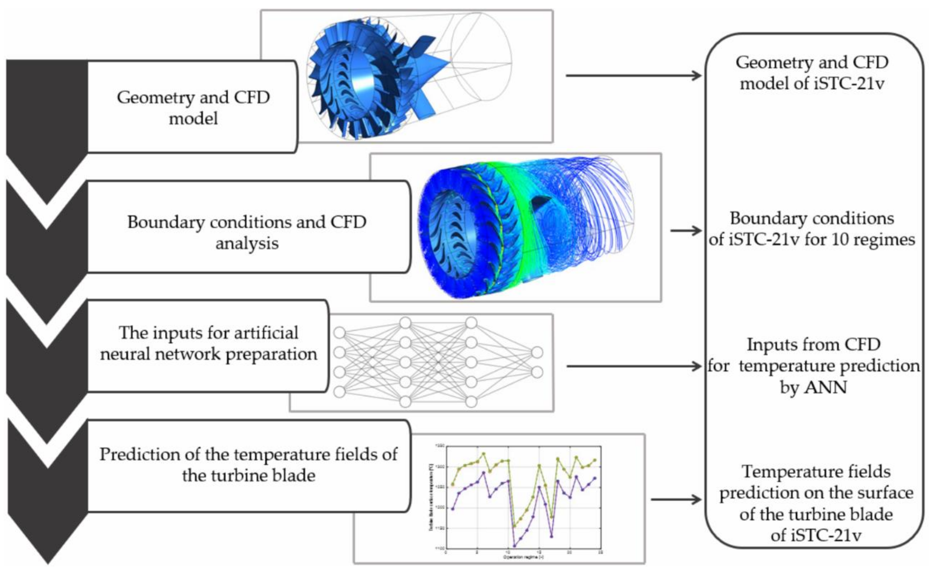
2.1. Methodology
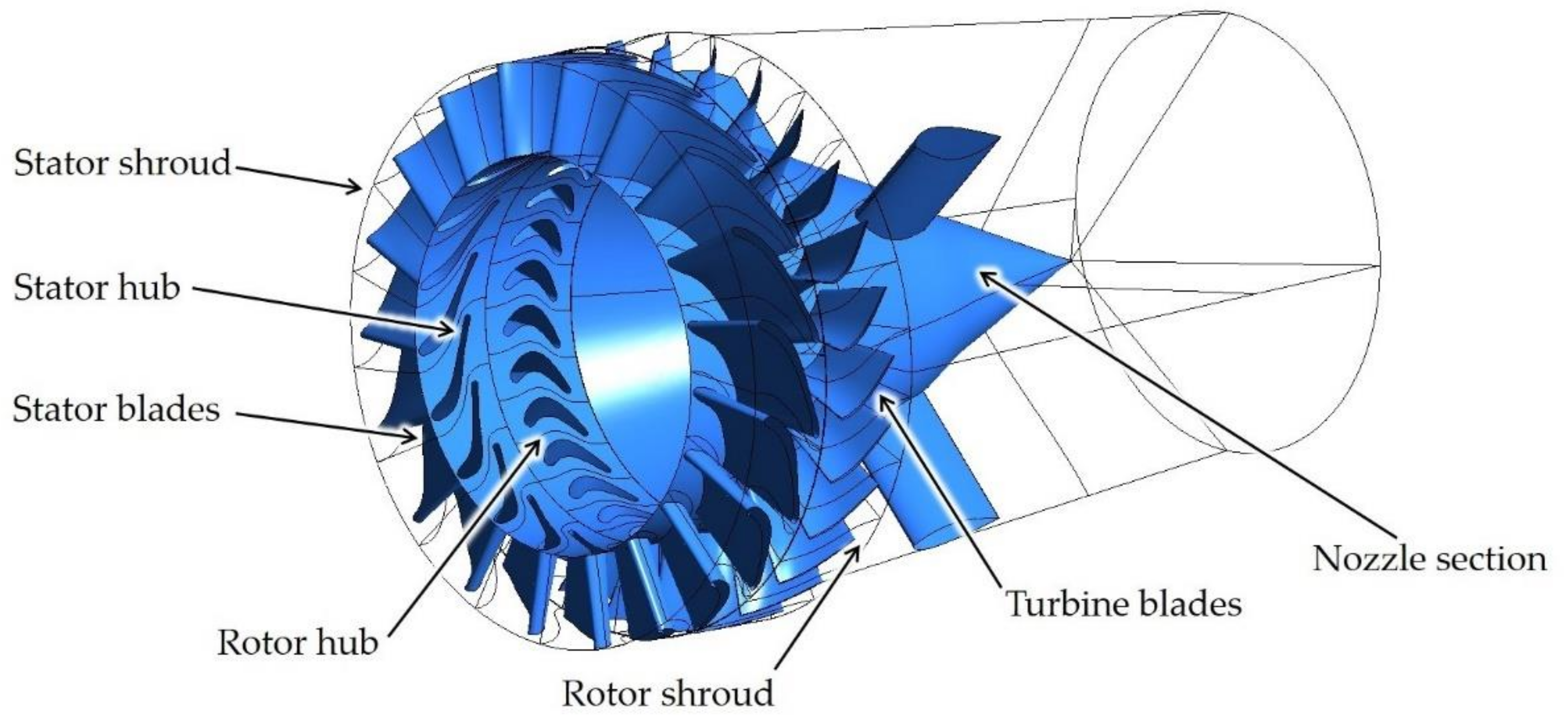
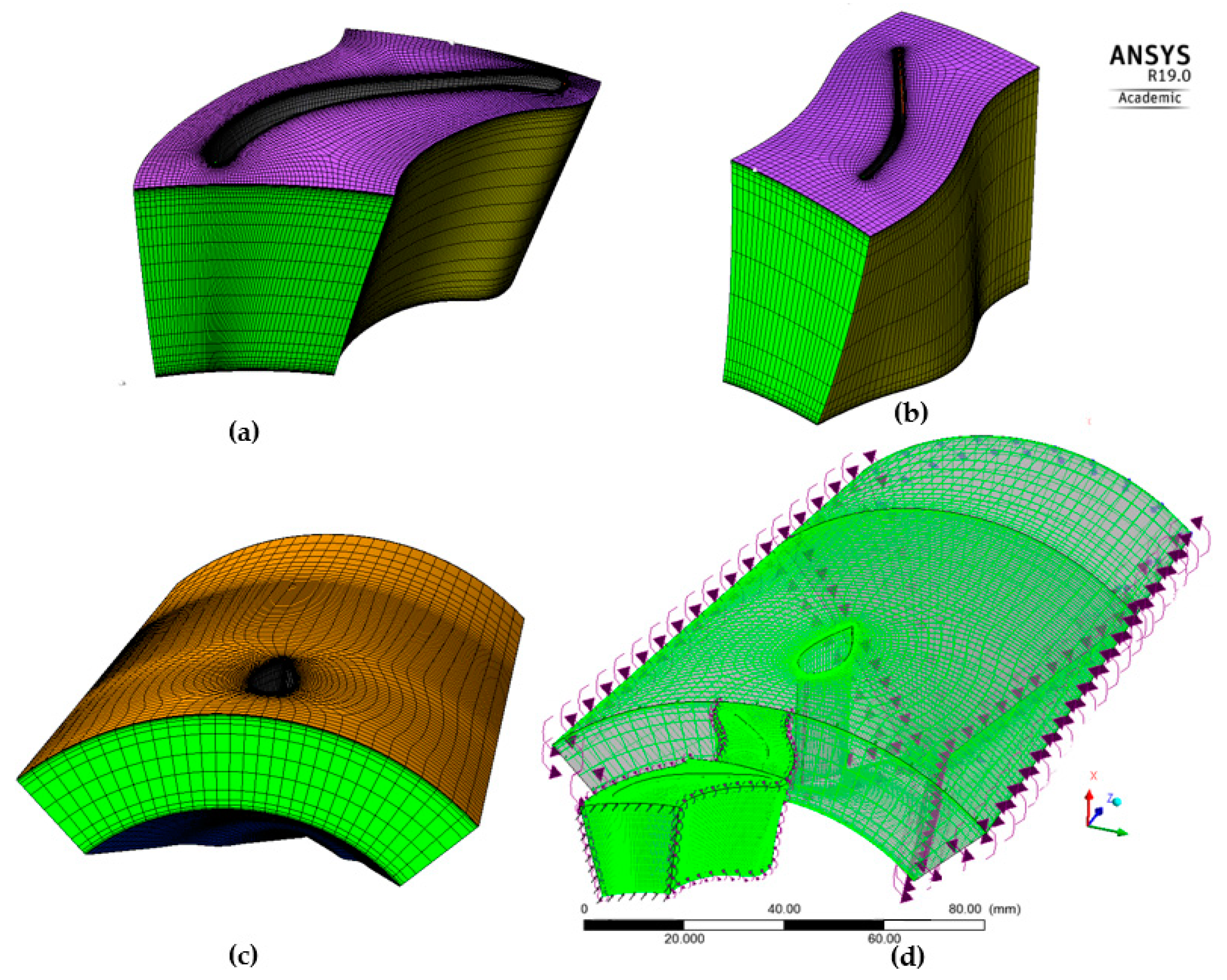
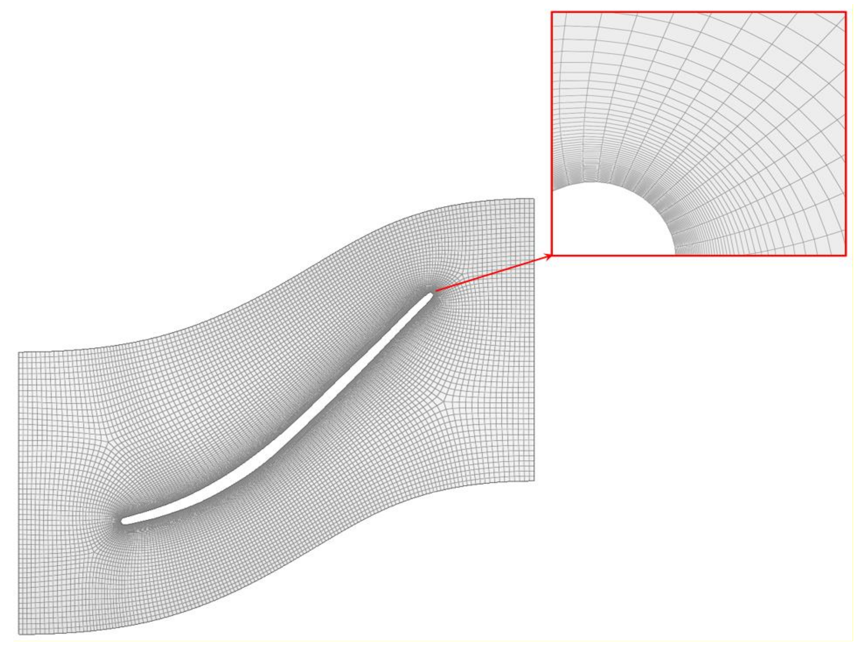
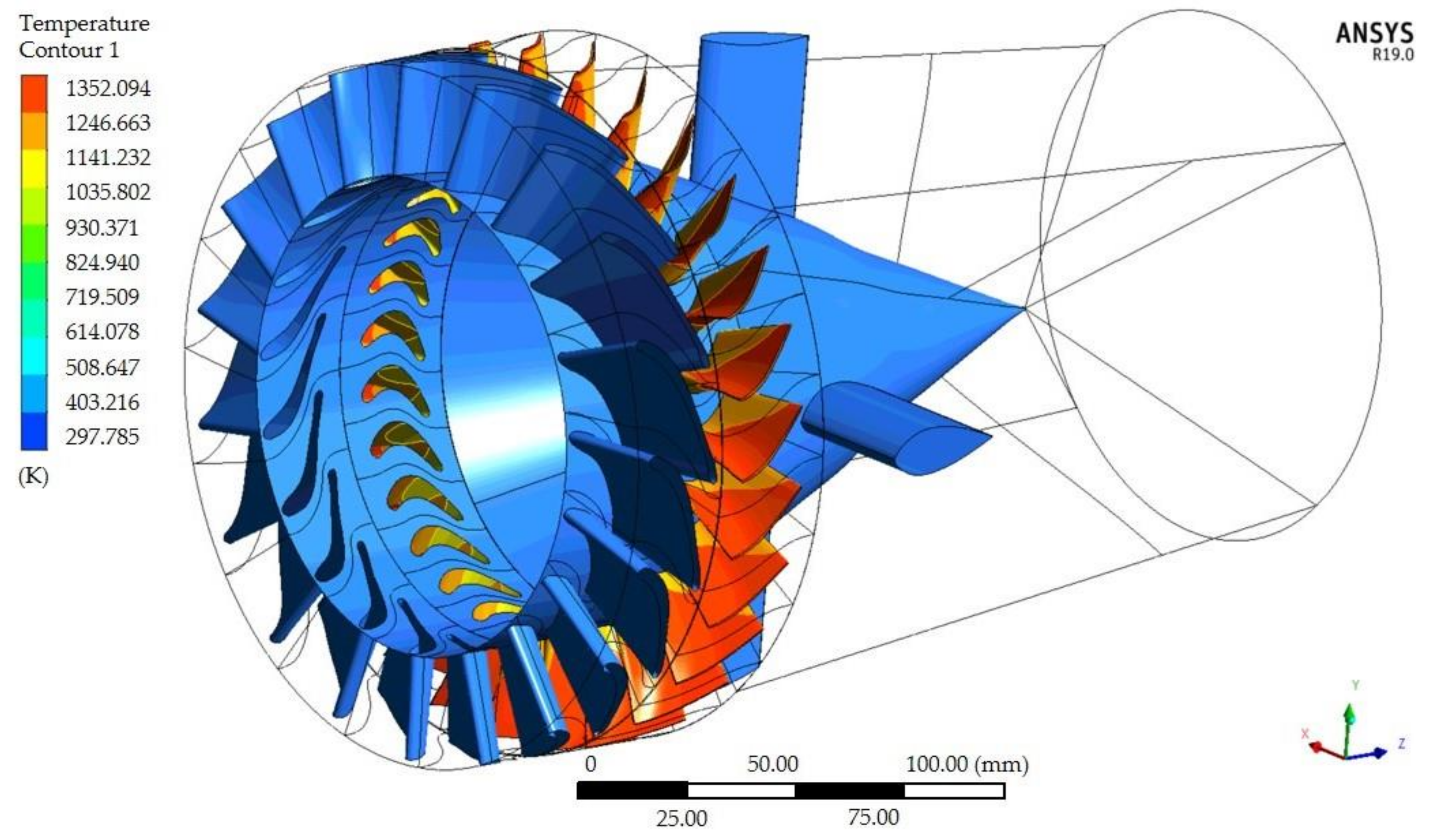
2.2. Theory and Application of the CFD Method
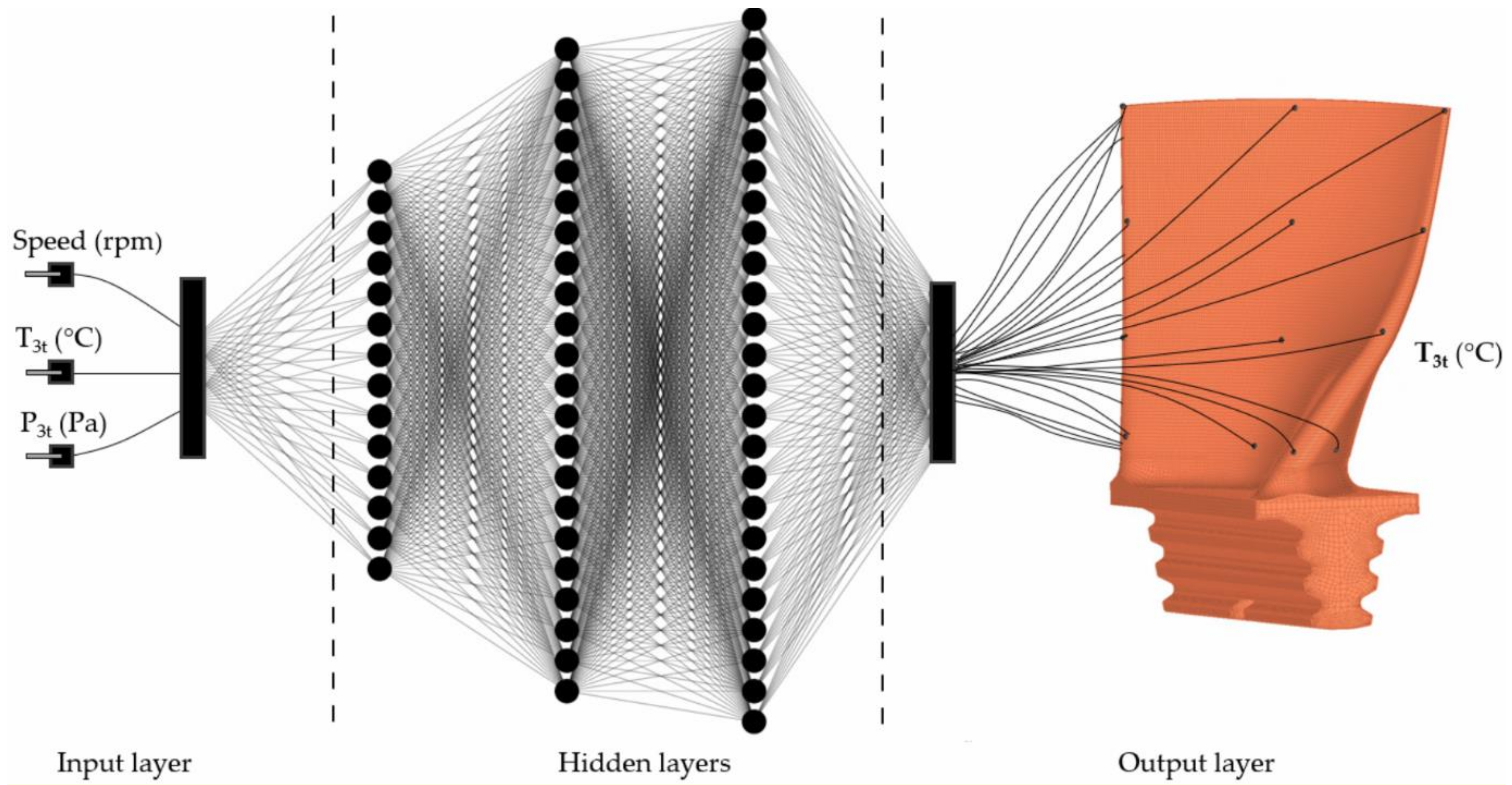
2.3. Theory and Application of the Method Based on the ANN
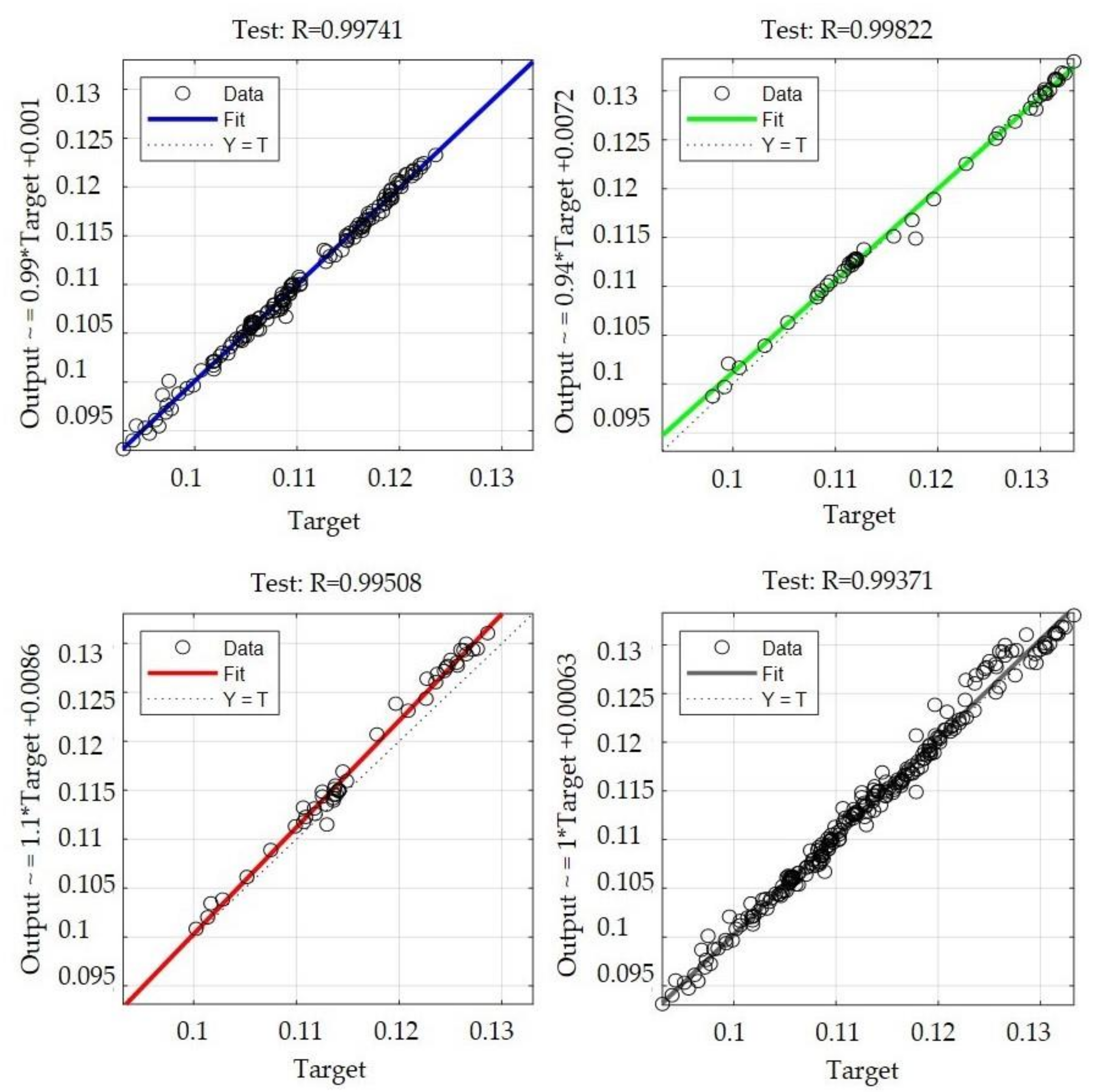
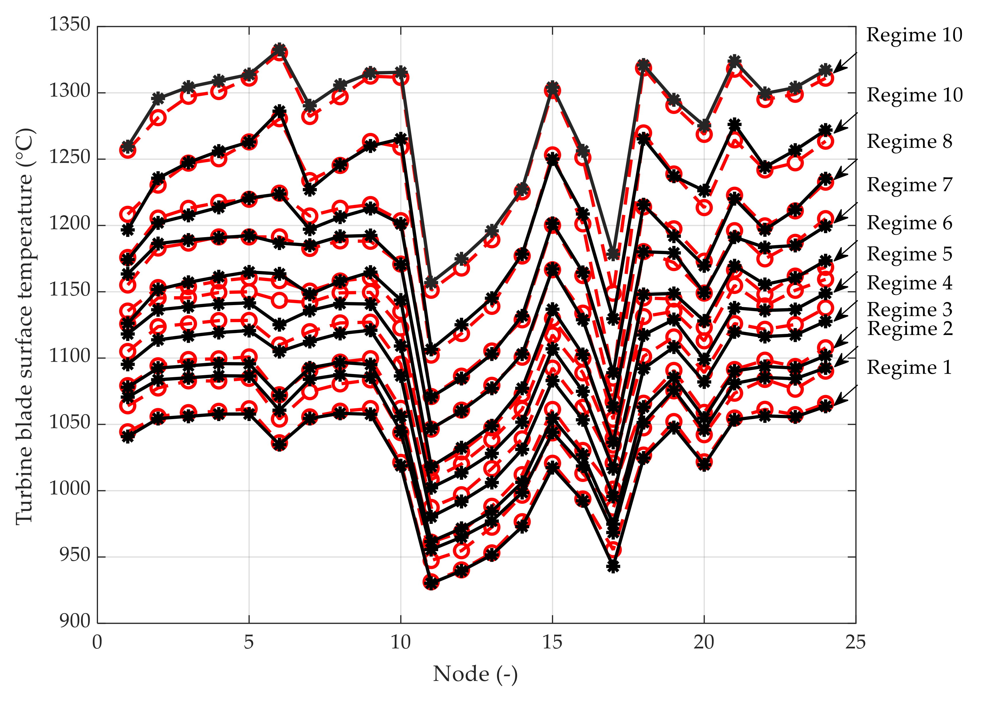
3. Results
4. Discussion
5. Conclusions
Author Contributions
Funding
Institutional Review Board Statement
Informed Consent Statement
Conflicts of Interest
References
- Royce, R. The Jet Engine, 5th ed.; John Wiley & Sons, Ltd on behalf of Rolls-Royce plc.: London, UK, 2015; ISBN 978-1-119-06599-9. [Google Scholar]
- Blachnio, J.; Bogdan, M.; Zasada, D. Increased Temperature Impact on Durability of Gas Turbine Blades. Eksploat. Niezawodn. 2017, 19, 48–53. [Google Scholar] [CrossRef]
- Janicki, G.; Pezouvanis, A.; Mason, B.; Ebrahimi, M.K. Turbine Blade Vibration Measurement Methods for Turbocharges. Am. J. Sens. Technol. 2014, 2, 13–19. Available online: http://pubs.sciepub.com/ajst/2/2/1/ (accessed on 22 January 2021).
- Rezazadeh Reyhani, M.; Alizadeh, M.; Fathi, A.; Khaledi, H. Turbine blade temperature calculation and life estimation—A sensitivity analysis. Propuls. Power Res. 2013, 2, 148–161. [Google Scholar] [CrossRef] [Green Version]
- Zhang, Z.; Yang, G.; Hu, K. Prediction of Fatigue Crack Growth in Gas Turbine Engine Blades Using Acoustic Emission. Sensors 2018, 18, 1321. [Google Scholar] [CrossRef] [Green Version]
- Vasilyev, B.; Nikolaev, S.; Raevskiy, M.; Belov, S.; Uzhinsky, I. Residual Life Prediction of Gas-Engine Turbine Blades Based on Damage Surrogate-Assisted Modeling. Appl. Sci. 2020, 10, 8541. [Google Scholar] [CrossRef]
- Zhu, S.-P.; Yue, P.; Yu, Z.-Y.; Wang, Q. A Combined High and Low Cycle Fatigue Model for Life Prediction of Turbine Blades. Materials 2017, 10, 698. [Google Scholar] [CrossRef] [PubMed] [Green Version]
- Mai, T.D.; Ryu, J. Effects of Leading-Edge Modification in Damaged Rotor Blades on Aerodynamic Characteristics of High-Pressure Gas Turbine. Mathematics 2020, 8, 2191. [Google Scholar] [CrossRef]
- Horlock, J.H.; Torbidoni, L. Turbine blade cooling: The blade temperature distribution. Proc. Inst. Mech. Eng. Part A J. Power Energy 2006, 220, 343–353. [Google Scholar] [CrossRef]
- Zhang, F.; Liu, Z.; Liu, Z.; Diao, W. Experimental Study of Sand Particle Deposition on a Film-Cooled Turbine Blade at Different Gas Temperatures and Angles of Attack. Energies 2020, 13, 811. [Google Scholar] [CrossRef] [Green Version]
- Masci, R.; Sciubba, E. A Gas Turbine Cooled-Stage Expansion Model for the Simulation of Blade Cooling Effects on Cycle Performance. Int. J. Turbomach. Propuls. Power 2019, 4, 36. [Google Scholar] [CrossRef] [Green Version]
- Granovskiy, A.; Gribin, V.; Lomakin, N. Experimental and Numerical Study of Transonic Cooled Turbine Blades. Int. J. Turbomach. Propuls. Power 2018, 3, 16. [Google Scholar] [CrossRef] [Green Version]
- Sakamoto, J.; Tada, N.; Uemori, T.; Kuniyasu, H. Finite Element Study of the Effect of Internal Cracks on Surface Profile Change due to Low Loading of Turbine Blade. Appl. Sci. Basel 2020, 10, 4883. [Google Scholar] [CrossRef]
- Miao, Q.; Li, H.N.; Ding, W.F. On the temperature field in the creep feed grinding of turbine blade root: Simulation and experiments. Int. J. Heat Mass. Transf. 2020, 147, 118957. [Google Scholar] [CrossRef]
- Tang, W.; Yang, L.; Zhu, W.; Zhou, Y.; Guo, J.; Lu, C. Numerical Simulation of Temperature Distribution and Thermal-Stress Field in a Turbine Blade with Multilayer-Structure TBCs by aFluid–Solid Coupling Method. J. Mater. Sci. Technol. 2016, 32, 452–458. [Google Scholar] [CrossRef]
- Zhu, W.; Wang, J.W.; Yang, L.; Zhou, Y.C.; Wei, Y.G.; Wu, R.T. Modeling and simulation of the temperature and stress fields in a 3D turbine blade coated with thermal barrier coatings. Surf. Coat. Tech. 2017, 315, 443–453. [Google Scholar] [CrossRef]
- Baheta, A.T.; Leong, K.P.; Sulaiman, S.A.; Fentaye, A.D. CFD Analysis of Fouling Effects on Aerodynamics Performance of Turbine Blades. In Rotating Machineries; Springer Singapore Pte Ltd: Singapore, 2018; pp. 73–84. [Google Scholar] [CrossRef]
- Bäcker, V.; Klocke, F.; Wegner, H.; Timmer, A.; Grzhibovskis, R.; Rjasanow, S. Analysis of the Deep Rolling Process on Turbine Blades using the FEM/BEM-Coupling. IOP Conf. Ser. Mat. Sci. 2010, 10, 012134. [Google Scholar] [CrossRef] [Green Version]
- Gantasala, S.; Luneno, J.-C.; Aidanpää, J.-O. Investigating How an Artificial Neural Network Model Can Be Used to Detect Added Mass on a Non-Rotating Beam Using Its Natural Frequencies: A Possible Application for Wind Turbine Blade Ice Detection. Energies 2017, 10, 184. [Google Scholar] [CrossRef] [Green Version]
- Zhang, C.-Y.; Wei, J.-S.; Wang, Z.; Yuan, Z.-S.; Fei, C.-W.; Lu, C. Creep-Based Reliability Evaluation of Turbine Blade-Tip Clearance with Novel Neural Network Regression. Materials 2019, 12, 3552. [Google Scholar] [CrossRef] [Green Version]
- Liu, X.; Liu, Z.; Liang, Z.; Zhu, S.-P.; Correia, J.A.F.O.; De Jesus, A.M.P. PSO-BP Neural Network-Based Strain Prediction of Wind Turbine Blades. Materials 2019, 12, 1889. [Google Scholar] [CrossRef] [Green Version]
- Liu, J.; Liu, J.; Yu, D.; Kang, M.; Yan, W.; Wang, Z.; Pecht, M.G. Fault Detection for Gas Turbine Hot Components Based on a Convolutional Neural Network. Energies 2018, 11, 2149. [Google Scholar] [CrossRef] [Green Version]
- Chan, Y.-K.; Gu, J.-C. Modeling of Turbine Cycles Using a Neuro-Fuzzy Based Approach to Predict Turbine-Generator Output for Nuclear Power Plants. Energies 2012, 5, 101–118. [Google Scholar] [CrossRef]
- Zhang, C.; Wei, J.; Jing, H.; Fei, C.; Tang, W. Reliability-Based Low Fatigue Life Analysis of Turbine Blisk with Generalized Regression Extreme Neural Network Method. Materials 2019, 12, 1545. [Google Scholar] [CrossRef] [Green Version]
- Zhao, Q.; Bao, K.; Wang, J.; Han, Y.; Wang, J. An Online Hybrid Model for Temperature Prediction of Wind Turbine Gearbox Components. Energies 2019, 12, 3920. [Google Scholar] [CrossRef] [Green Version]
- Khan, F.; Eker, O.F.; Khan, A.; Orfali, W. Adaptive Degradation Prognostic Reasoning by Particle Filter with a Neural Network Degradation Model for Turbofan Jet Engine. Data 2018, 3, 49. [Google Scholar] [CrossRef] [Green Version]
- Kozakiewicz, A.; Jóźwiak, S.; Jóźwiak, P.; Kachel, S. Material Origins of the Accelerated Operational Wear of RD-33 Engine Blades. Materials 2021, 14, 336. [Google Scholar] [CrossRef]
- Ciampolini, M.; Bigalli, S.; Balduzzi, F.; Bianchini, A.; Romani, L.; Ferrara, G. CFD Analysis of the Fuel–Air Mixture Formation Process in Passive Prechambers for Use in a High-Pressure Direct Injection (HPDI) Two-Stroke Engine. Energies 2020, 13, 2846. [Google Scholar] [CrossRef]
- Andoga, R.; Főző, L.; Schrötter, M.; Češkovič, M.; Szabo, S.; Bréda, R.; Schreiner, M. Intelligent Thermal Imaging-Based Diagnostics of Turbojet Engines. Appl. Sci. Basel 2019, 9, 2253. [Google Scholar] [CrossRef] [Green Version]
- Andoga, R.; Főző, L.; Kovács, R.; Beneda, K.; Moravec, T.; Schreiner, M. Robust Control of Small Turbojet Engines. Machines 2019, 7, 3. [Google Scholar] [CrossRef] [Green Version]
- Spodniak, M.; Semrád, K.; Főző, L.; Pavlinský, J. FEM analysis of natural frequencies of jet engine iSTC-21v turbine blade. In Proceedings of the SAMI 2019, IEEE 17th World Symposium on Applied Machine Intelligence and Informatics, Herlany, Slovakia, 24–26 January 2019; pp. 287–292. [Google Scholar] [CrossRef]
- Beneda, K.; Andoga, R.; Főző, L. Linear Mathematical Model for State-Space Representation of Small Scale Turbojet Engine with Variable Exhaust Nozzle. Period. Polytech. Transp. Eng. 2017, 46, 1–10. [Google Scholar] [CrossRef] [Green Version]
- Andoga, R.; Főző, L. Near Magnetic Field of a Small Turbojet Engine. Acta Phys. Pol. A 2017, 131, 1117–1119. [Google Scholar] [CrossRef]
- Főző, L.; Andoga, A.; Kovács, L.; Schreiner, M.; Beneda, K.; Savka, J.; Soušek, R. Virtual Design of Advanced Control Algorithms for Small Turbojet Engines. Acta Polytec. Hung. 2019, 16, 101–117. [Google Scholar] [CrossRef]
- Kovács, R.; Főző, L.; Andoga, R. Calculation of flow in the gas turbine and the outlet tract using CFD methods. In Proceedings of the CINTI 2015-16th IEEE International Symposium on Computational Intelligence and Informatics, Budapest, Hungary, 19–21 November 2015; pp. 75–78. [Google Scholar] [CrossRef]
- Korkmaz, K.B.; Werner, S.; Bensow, R. Verification and Validation of CFD Based Form Factors as a Combined CFD/EFD Method. J. Mar. Sci. Eng. 2021, 9, 75. [Google Scholar] [CrossRef]
- Song, X.; Liu, M.; Hu, X.; Wang, X.; Liao, T.; Sun, J. Numerical Analysis of Flow across Brush Elements Based on a 2-D Staggered Tube Banks Model. Aerospace 2021, 8, 19. [Google Scholar] [CrossRef]
- Sinagra, M.; Picone, C.; Aricò, C.; Pantano, A.; Tucciarelli, T.; Hannachi, M.; Driss, Z. Impeller Optimization in Crossflow Hydraulic Turbines. Water 2021, 13, 313. [Google Scholar] [CrossRef]
- Shrestha, U.; Choi, Y.-D. A CFD-Based Shape Design Optimization Process of Fixed Flow Passages in a Francis Hydro Turbine. Processes 2020, 8, 1392. [Google Scholar] [CrossRef]
- Celik, A.; Bonten, C.; Togni, R.; Kloss, C.; Goniva, C. A Novel Modeling Approach for Plastics Melting within a CFD-DEM Framework. Polymers 2021, 13, 227. [Google Scholar] [CrossRef]
- Zhang, W.; Li, L.; Zhang, B.; Xu, X.; Zhai, J.; Wang, J. A Closed-Loop Optimized System with CFD Data for Liquid Maldistribution Model. Processes 2020, 8, 1332. [Google Scholar] [CrossRef]
- Kliment, T.; Praslička, D.; Lipovský, P.; Draganová, K.; Zavodsky, O. Calibration of magnetometer for small satellites using neural network. Acta Phys. Pol. A 2017, 131, 1129–1131. [Google Scholar] [CrossRef]
- Andoga, R.; Draganová, K.; Laššák, M. Inverse Neural Network Controller for Camera Gimbal Stabilization. Acta Avion. 2016, 18, 1–6. [Google Scholar]
- Recio-Colmenares, R.; Gurubel-Tun, K.J.; Zúñiga-Grajeda, V. Optimal Neural Tracking Control with Metaheuristic Parameter Identification for Uncertain Nonlinear Systems with Disturbances. Appl. Sci. Basel 2020, 10, 7073. [Google Scholar] [CrossRef]
- Lee, A.; Geem, Z.W.; Suh, K.-D. Determination of Optimal Initial Weights of an Artificial Neural Network by Using the Harmony Search Algorithm: Application to Breakwater Armor Stones. Appl. Sci. Basel 2016, 6, 164. [Google Scholar] [CrossRef] [Green Version]
- Deng, Q.; Shao, S.; Fu, L.; Luan, H.; Feng, Z. An Integrated Design and Optimization Approach for Radial Inflow Turbines—Part II: Multidisciplinary Optimization Design. Appl. Sci. Basel 2018, 8, 2030. [Google Scholar] [CrossRef] [Green Version]
- Annala, L.; Äyrämö, S.; Pölönen, I. Comparison of Machine Learning Methods in Stochastic Skin Optical Model Inversion. Appl. Sci. Basel 2020, 10, 7097. [Google Scholar] [CrossRef]
- Draganová, K.; Laššák, M.; Praslička, D.; Kán, V. Attitude-Independent 3-axis accelerometer calibration based on adaptive neural network. Procedia Eng. 2014, 87, 1255–1258. [Google Scholar] [CrossRef] [Green Version]
- Spodniak, M.; Semrád, K.; Šmelko, M.; Főző, L.; Andoga, R.; Draganová, K.; Szabo, S. Estimation of Magnetic Microwire Mechanical Properties by FEM Modeling. Acta Phys. Pol. A 2020, 137, 674–676. [Google Scholar] [CrossRef]


| Regime | Temperature-T3t (°C) | Pressure-P3t (Pa) | Speed (rpm) |
|---|---|---|---|
| 1 | 824.0 | 197,700 | 36,079 |
| 2 | 851.0 | 197,900 | 36,110 |
| 3 | 862.6 | 211,300 | 37,920 |
| 4 | 891.3 | 229,000 | 39,960 |
| 5 | 914.3 | 264,400 | 41,660 |
| 6 | 942.9 | 268,200 | 44,080 |
| 7 | 977.9 | 288,100 | 46,020 |
| 8 | 1007.0 | 307,300 | 47,860 |
| 9 | 1067.0 | 339,100 | 50,120 |
| 10 | 1127.0 | 361,300 | 51,990 |
| Coordinate X | Coordinate Y | Coordinate Z | Temperature (°C) |
|---|---|---|---|
| 80.062 | 6.408 | 3.538 | 1044.510 |
| 55.084 | 2.013 | 14.732 | 955.635 |
| 60.602 | 2.115 | 13.566 | 964.962 |
| 65.514 | 1.040 | 13.765 | 977.080 |
| 72.748 | −0.077 | 13.519 | 998.633 |
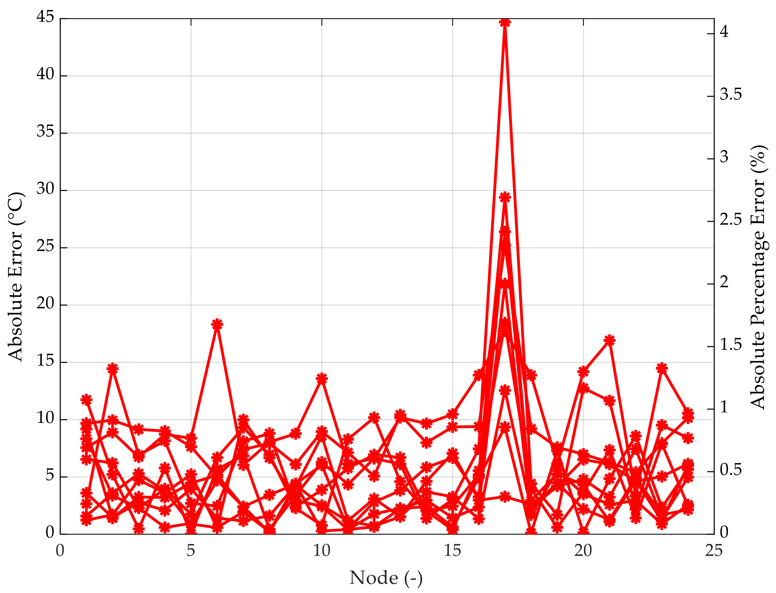
| MAE (°C) | MAPE (%) | Max. Difference (°C) |
|---|---|---|
| 5.59 | 0.5 | 44.7 |
Publisher’s Note: MDPI stays neutral with regard to jurisdictional claims in published maps and institutional affiliations. |
© 2021 by the authors. Licensee MDPI, Basel, Switzerland. This article is an open access article distributed under the terms and conditions of the Creative Commons Attribution (CC BY) license (http://creativecommons.org/licenses/by/4.0/).
Share and Cite
Spodniak, M.; Semrád, K.; Draganová, K. Turbine Blade Temperature Field Prediction Using the Numerical Methods. Appl. Sci. 2021, 11, 2870. https://doi.org/10.3390/app11062870
Spodniak M, Semrád K, Draganová K. Turbine Blade Temperature Field Prediction Using the Numerical Methods. Applied Sciences. 2021; 11(6):2870. https://doi.org/10.3390/app11062870
Chicago/Turabian StyleSpodniak, Miroslav, Karol Semrád, and Katarína Draganová. 2021. "Turbine Blade Temperature Field Prediction Using the Numerical Methods" Applied Sciences 11, no. 6: 2870. https://doi.org/10.3390/app11062870