Article

Current Ripple Reduction of Predictive Torque-Controlled Induction Motor Drive Using Delta-Star Switchover

Department of Electric Drives and Traction, Czech Technical University in Prague, 160 00 Prague, Czech Republic
*
Author to whom correspondence should be addressed.
Appl. Sci. 2021, 11(6), 2863; https://doi.org/10.3390/app11062863
Submission received: 22 February 2021 / Revised: 18 March 2021 / Accepted: 19 March 2021 / Published: 23 March 2021
(This article belongs to the Section Electrical, Electronics and Communications Engineering)

Abstract

:
The current and torque ripple of inverter-fed induction motor drives is an inherent problem of control strategies working with switching frequencies in the range of multiple kilohertz, such as direct torque and, more recently, predictive torque control. If the drive operates in a wide-speed and wide-torque range and is equipped with a machine with an accessible terminal block whose winding is nominally connected in delta, then the current and torque ripple can be reduced by utilizing the delta-star winding changeover technique. When the winding configuration is switched from delta to star, the instantaneous motor phase voltage peak is lowered, and its total harmonic distortion is reduced. However, the control strategy must be adjusted according to the actual winding topology, mainly due to the difference in the coordinate transformations of the measured currents and the difference between the phase voltage vectors obtained from the inverter. This paper proposes a predictive torque control of an induction motor drive with a switchable delta-star winding configuration. The paper is supported by theoretical background, and the key idea is verified by simulations in MATLAB/Simulink and experiments conducted on a dSPACE-controlled 5.5-kW laboratory drive. The simulations validated the presented equations and show the effects of not respecting the actual winding topology. The experiments mainly focused on analyzing the total harmonic distortion of the currents and consumed electrical power in multiple operating points.

1. Introduction

Induction motor (IM) is still one of the most widely used types of rotating electrical machine. The typical control of modern inverter-fed IM drives utilizes either the direct torque control (DTC) or field-oriented control (FOC) [1]. However, as another perspective strategy, the model predictive control (MPC) has received attention in recent years [2,3,4]. MPC aims to search for an optimal inverter voltage vector, which brings the system closest to the reference values. This optimum is mathematically expressed via the so-called cost function and is found analytically or by enumerating the whole feasible set. One of the typical MPC implementations in electric drives is predictive torque control (PTC), which regulates the developed torque and stator flux amplitude. The PTC avoids using a modulator, so only the eight fundamental voltage vectors are considered feasible candidates within a two-level inverter. This makes the searching for the optimal voltage vector more straightforward since the cost function must be enumerated only eight times.
The torque and flux amplitude control approach using only eight voltage vectors remains the same for the DTC and PTC [4]. Because of this similarity, the drawback of increased current and torque ripple is also shared [5]. Several approaches suppressing the ripple were introduced in the literature. Most of them reduce the current ripple at the cost of increased switching frequency, i.e., shorter sampling time [6], variable switching point [7], or extended feasible set by space-vector modulation (SVM) [8], which is not admissible in many applications due to the increased switching losses. Other solutions are based on hardware modification, i.e., the utilization of multi-level inverters [9,10] or adjustable DC-link voltage [11,12]. The ability to suppress the current ripple by software without the switching frequency increase is possible only to some extent. Such an approach lies within the cost function design focused on the switching frequency decrease [6], the efficient zero voltage vector selection [13], or optimal duty-cycle control [3]. Moderate improvements were also achieved with an extended prediction horizon [6,14].
The IMs utilized in the industry are designed to operate either in star or delta winding configuration. Online winding changeover techniques are a common practice either for inverter-fed [15,16,17,18,19,20] or for direct-online (DOL) [21,22,23] operated electrical machines. Within DOL motors, star-delta switches are predominantly used to improve the motor power factor and efficiency. The primary purpose of winding configuration changeover in inverter-fed machines is to extend the base-speed range, either by a star-delta switch or using a center tap in the winding. The winding configuration can then be altered either with a mechanical contactor or semiconductor switch.
This paper investigates another merit of winding changeover—the possibility of using an online delta-star winding switchover for the current and torque ripple reduction of a PTC-controlled IM drive. By switching from delta to star at a constant DC-link voltage, the inverter voltage vectors’ magnitude is decreased by a factor 3 , which lowers the drive torque capabilities at higher speeds. On the other hand, the peak instantaneous motor phase voltage is reduced 1.5times, and two voltage levels ( ± 1 / 3 of the DC-link voltage) are added. This leads to lower current and torque ripple, and improved efficiency since the total harmonic distortion (THD) of the machine currents directly contributes to power losses [12,24].
Publications on predictive control of IM drive (or control of IM drives in general) usually silently assume the use of a star-connected motor [25]. However, if the machine is delta-connected, the current and voltage transformations and the control algorithm have to be adjusted [26]. The investigation presented in this paper aims at medium power IM drives controlled by PTC with machines designed to operate in the delta-winding connection nominally. Our paper shows that if such a drive is completed with a controllable (either mechanical or solid-state) delta-star switch, then in some working points (i.e., below the rated speed and torque), it is beneficial to operate the machine in the star configuration, because both the current ripple and consumed electrical power can be reduced.
The presented PTC algorithm with switchable delta-star winding topology is supported by theoretical analysis, simulations in MATLAB/Simulink, and experiments conducted on a 5.5-kW dSpace-controlled IM laboratory drive. The simulations verify the presented space-vector equations of the delta-connected machine and analyze the effects of not respecting the actual winding topology. The experimental results confirm the current ripple reduction and efficiency increase by a comprehensive analysis of the current THD and consumed electrical power in multiple operating points of a star-operated but nominally delta-designed machine.
The paper is organized as follows: The first part of Section 2 derives the necessary modifications in the transformation of the measured inverter output currents in the case of a delta-connected machine. The second part of the section emphasizes the differences between the fundamental motor phase voltage vectors created by the inverter for both topologies. Section 3 analyzes the constraints imposed on the flux, torque, and speed control of a machine with a switchable delta-star winding connection and provides information about the PTC algorithm’s design. Section 4 is dedicated to simulation and experimental results. The paper is concluded with Section 5 that contains a discussion about the proposed method and achieved results. The symbols used throughout the paper are defined in a list before the Appendix A.

2. Current and Voltage Transformations of Delta-Connected Machine

The PTC algorithm is based on the machine’s mathematical model for which the space vector theory is commonly utilized. However, the theory utilizes the machine phase voltages and currents. If the winding is delta-connected, then the currents measured at the inverter output are line currents that differ from the phase currents both in phase and magnitude. Therefore, it is necessary to modify the mathematical transformations that are used in conjunction with a star-connected machine.
Another important difference that must be considered within the delta winding topology is that for the same inverter switching combinations, different motor phase voltage vectors are created (inverter line-to-line voltage now becomes motor phase voltage). As opposed to a star connection, the voltage vectors are again shifted both in phase and amplitude and have a different effect on the flux and torque control.
The modifications in the current transformations and the differences between the phase voltage vectors are mathematically analyzed in the following two sections.

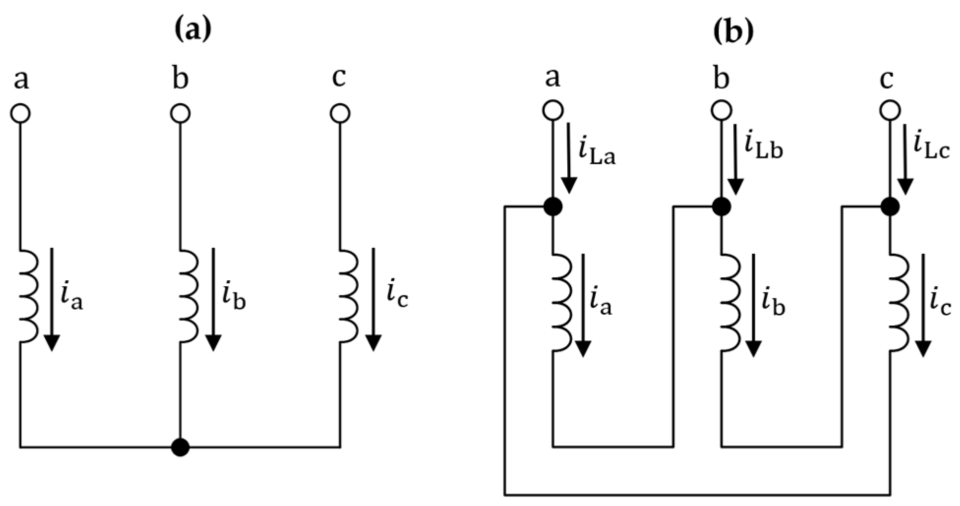
2.1. Current Transformations

Figure 1 shows the basic winding diagram of the star- and delta-connected IM. If the machine is star-connected (Figure 1a), then the measured currents at the inverter output directly correspond to the phase current of the individual windings. The transformation of the measured currents to the phase current space-vector can be expressed as
i _ 1 = K ( i a + i b a + i c a 2 ) .
In the following text, if the space vectors are not written in an arbitrary form, then the transformation constant is considered equal to 2 / 3 .
In the delta-connected IM (Figure 1b), the measured currents at the inverter output are related to the phase currents as
i La = i a i c ,
i Lb = i b i a ,
i Lc = i c i b .
The space vector of the line currents can be written as
i _ 1 L = K ( i La + i Lb a + i Lc a 2 ) .
Substituting (2)–(4) to (5) yields
i _ 1 = 1 3 i _ 1 L e π 6 .
Equation (6) enables calculating the space vector of the phase currents out of the space vector of the line currents of a delta-connected machine. Furthermore, out of (2)–(4), it follows that
i La + i Lb + i Lc = 0 .
However, (7) only holds for the line currents and not the phase currents, which can exhibit circular current components. Considering (7), separation of (6) to real and imaginary part, respectively, yields
i 1 α = 1 2 K ( i La i Lb ) ,
i 1 β = 3 2 K ( i La + i Lb ) .
For the most common choice of K = 2 / 3 , (8) and (9) can be finally rewritten as
i 1 α = 1 3 ( i La i Lb ) ,
i 1 β = 1 3 ( i La + i Lb ) .

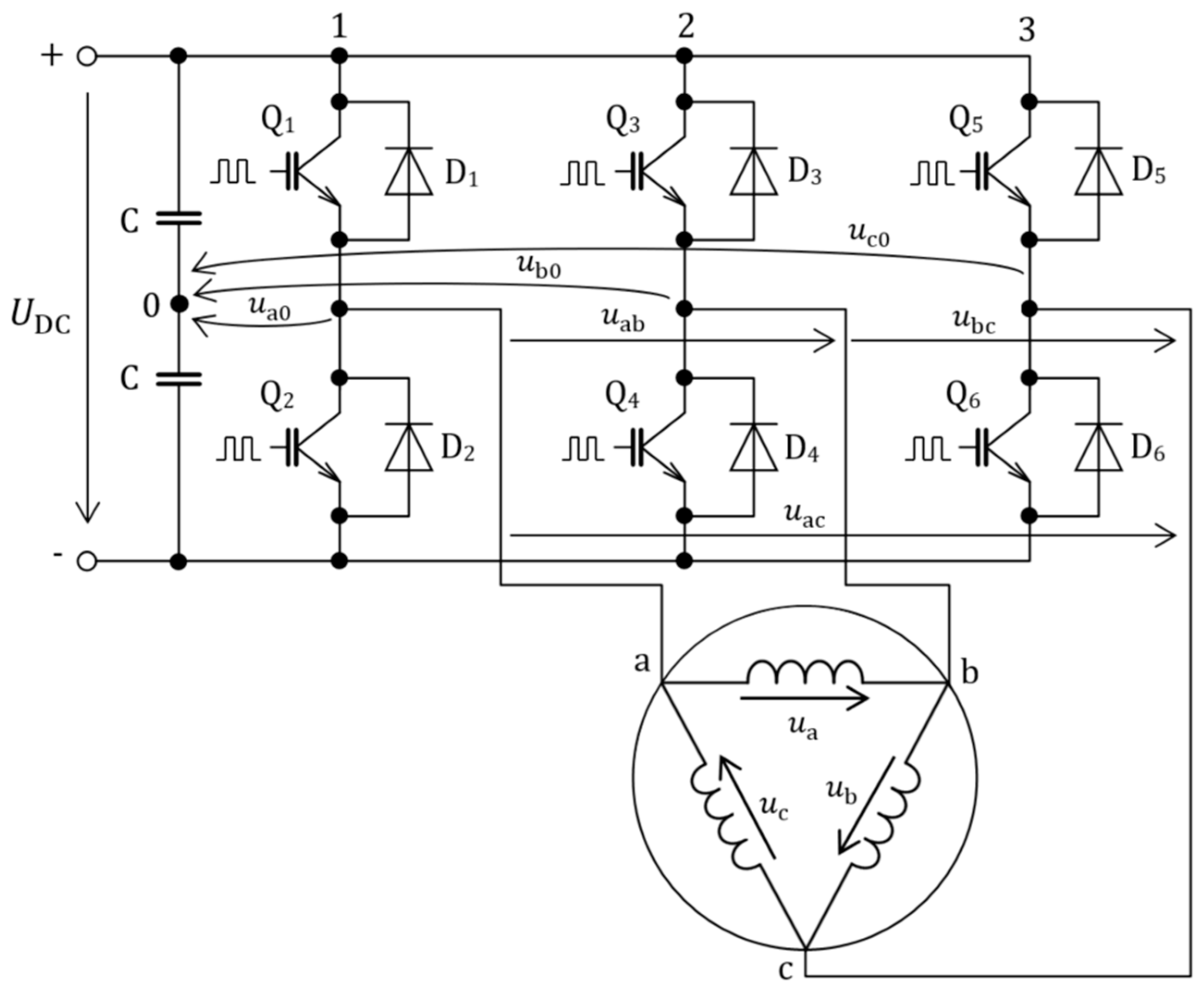
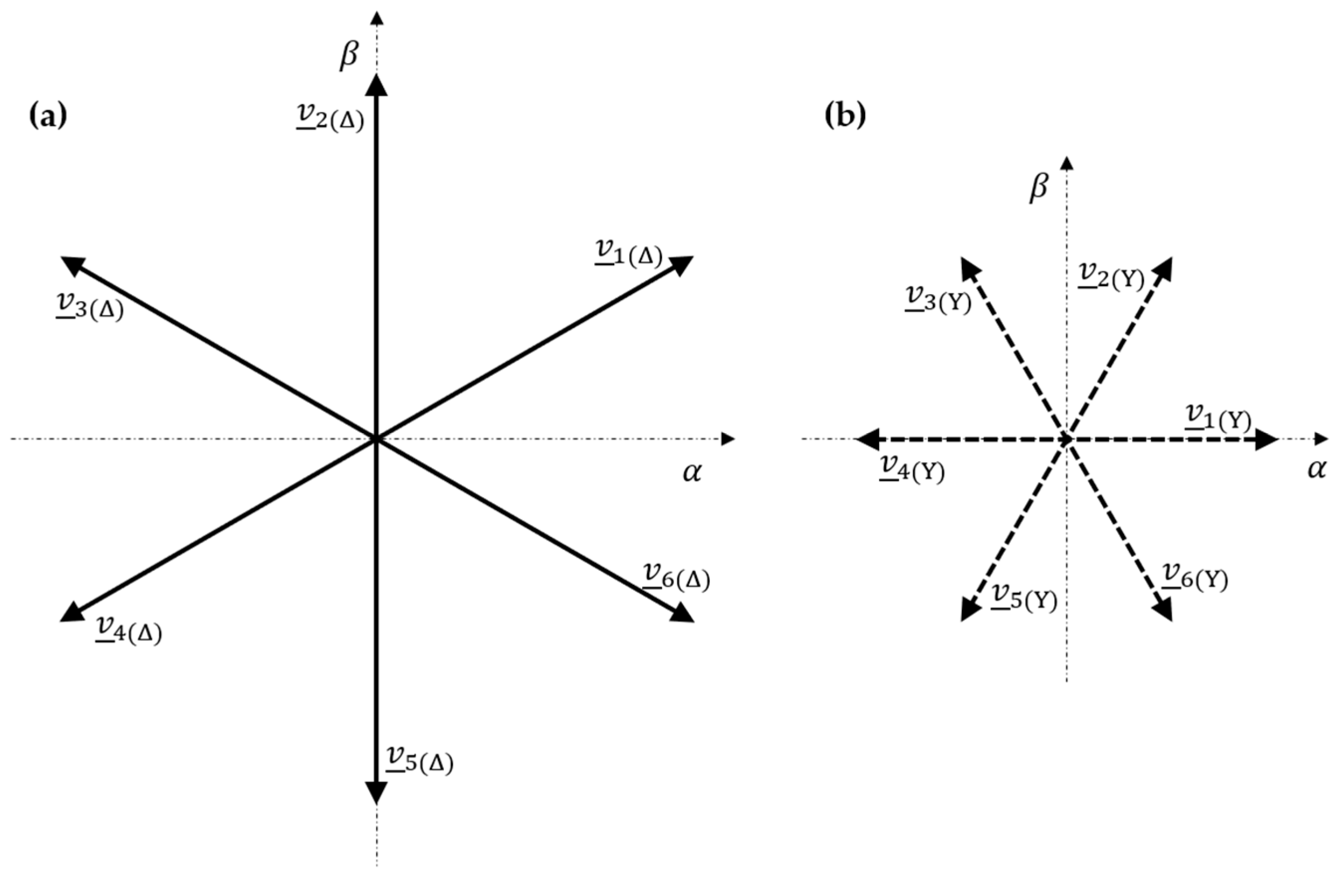
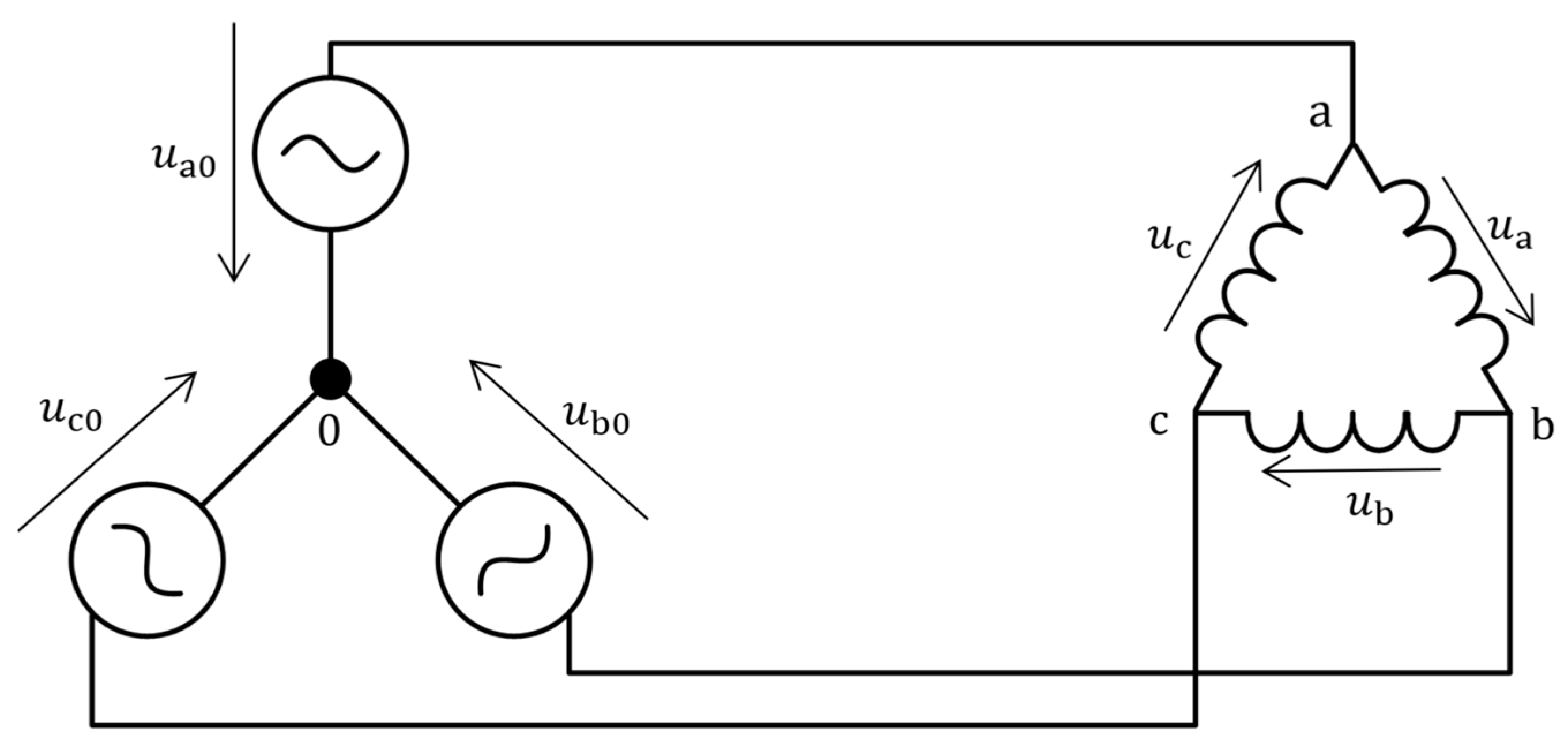
2.2. Voltage Transformations

Figure 2 shows a three-phase two-level voltage-source inverter supplying a delta-connected IM. The interconnection of phases is equal to that defined in Figure 1. Table 1 then shows the phase voltages and the resulting phase voltage space vectors for the individual inverter switching combinations (“1” corresponds to the upper switch being on and “0” corresponds to the lower switch being on, the sequence corresponds to the inverter leg numbering from Figure 2).
In a star connection, the active phase voltage vectors can be expressed in a general form as
v _ κ ( Y ) = 2 3 U DC e j ( k 1 ) π 3 ,
where κ {   1 ,   2 ,   3 ,   4 ,   5 ,   6 } . Therefore, the relationship between the star and delta voltage vectors for the same switching combination is given by
v _ κ ( Δ ) = 3 e π 6 v _ k ( Y ) .
A comparison of the six active voltage vectors for a delta and star winding configuration and a constant DC-link voltage is shown in Figure 3.
Voltage reconstruction from the switching signals can be obtained with the help of Figure 4. First, the motor phase voltages are expressed in terms of the inverter phase voltages (defined in Figure 2) as
u a = u a 0 u b 0 ,
u b = u b 0 u c 0 ,
u c = u c 0 u a 0 ,
or more conveniently in a matrix form
[ u a u b u c ] = [ 1 1 0 0 1 1 1 0 1 ] [ u a 0 u b 0 u c 0 ] .
Neglecting the dead-time effects and finite switching times, the inverter phase voltages can take two values: + U DC / 2 if an upper switch is on, and U DC / 2 if a lower switch is on. This can be summarized as
u x 0 = U DC 2 ( 2 S x 1 ) x = a , b , c .
Finally, the motor phase voltages can be reconstructed using (14)–(16) and (18) as
u a = ( S a S b ) U DC ,
u b = ( S b S c ) U DC ,
u c = ( S c S a ) U DC .
Transferring (19)–(21) into matrix form then gives
[ u a u b u c ] = U DC [ 1 1 0 0 1 1 1 0 1 ] [ S a S b S c ] .

3. Predictive Torque Control with Switchable Delta-Star Winding Configuration

3.1. Considerations about Flux, Torque, and Speed Control

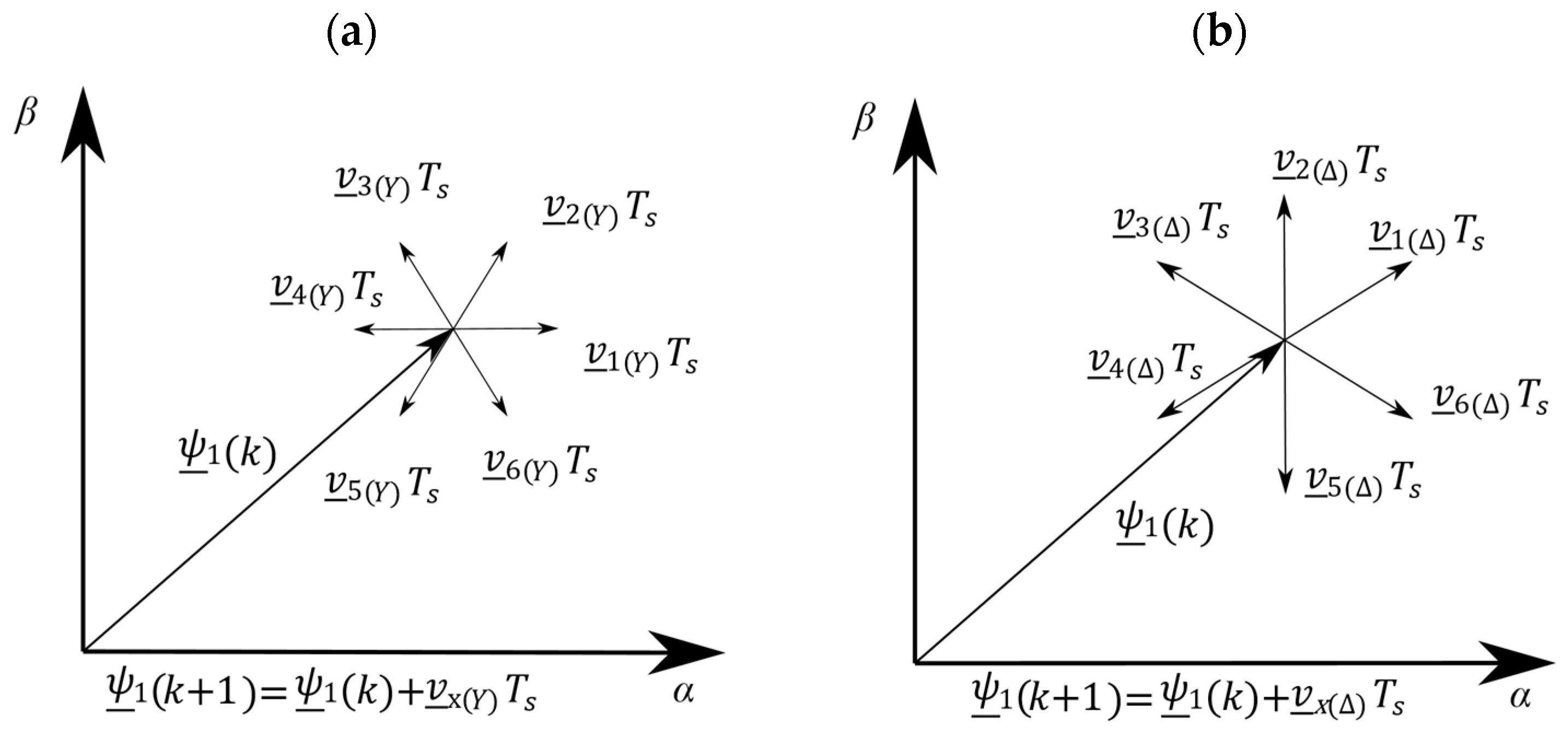
3.1.1. Control of Flux by Active Voltage Vectors

PTC’s principle is based on the conventional DTC strategy, which utilizes the stator voltage vector equation in the stationary α β system for the flux and torque control. At higher speeds, i.e., higher supply frequencies, the magnitude of the stator (i.e., the leakage and magnetizing) reactance becomes much more significant than the stator resistance. Therefore, neglecting the stator resistance and considering finite differences (denoted as δ ), the stator voltage equation can be written as
δ ψ _ 1 δ t u _ 1             δ ψ _ 1 u _ 1 δ t .
The magnitude of change of the stator flux linkage vector caused by applying an arbitrary active voltage vector for a time duration δ t 0 can be expressed in the case of a star-connected machine ( K = 2 / 3 ) as
δ ψ 1 ( Y ) 2 3 U DC δ t 0 ,
and in the case of a delta-connected machine as
δ ψ 1 ( Δ ) 2 3   U DC δ t 0 .
A comparison of (24) and (25) shows that
δ ψ 1 ( Y ) = 1 3 δ ψ 1 ( Δ ) .
For a constant DC-link voltage value and a fixed duration of an active inverter voltage vector, the absolute value of change of the stator flux linkage vector is 3 times higher in case of a delta-connected winding.

3.1.2. Flux Command Limitation

Suppose that the machine is designed to nominally operate at a line-to-line supply voltage U n and frequency f n . Neglecting the stator resistance, the nominal stator flux linkage vector magnitude ( K = 2 / 3 ) can be for a nominally star-connected machine written as
ψ 1 n ( Y ) = U n 6 π f n ,
and for a nominally delta-connected machine as
ψ 1 n ( Δ ) = U n 2 π f n .
A comparison of (27) and (28) shows that
ψ 1 n ( Y ) = 1 3 ψ 1 n ( Δ ) .
If an inverter-fed machine is designed to operate in a delta-connection, then the IM cannot establish nominal flux at higher speeds when the winding connection is switched from delta to star due to the lack of voltage for countering the back-electromotive force (BEMF). To reach the nominal speed after the winding changeover from delta to star, the excitation flux must be reduced, which leads to lowered torque capability. These limitations, which will be further discussed in the following sections, should be considered in the control algorithm.

3.1.3. Utilizable Speed Range

The base speed, i.e., the maximum achievable rotor speed under a nominal excitation and nominal stator current, can be expressed as [27]
ω r ( base ) = U max L 1 σ 2 I 1 max 2 + ( 1 σ 2 ) I 1 d ( n ) 2 .
When the winding connection is switched from delta to star, the maximum achievable voltage is reduced by the factor 3 . If the flux is kept at the same level, it follows that
ω r ( base ) = 1 3 ω r ( base ) .
Using the relationship between the stator flux linkage vector magnitude and the d -axis flux-producing current component (see Appendix A for derivation)
i 1 d = L 2 L m ψ 1 2 L 1 2 σ 2 I 1 max 2 L m 2 + 2 L 1 L 2 σ ,
it can be derived that for the preservation of the same base-speed region, the nominal d -axis flux-producing current component must be scaled by the factor
k scale = 1 3 1 + 2 I 1 max 2 σ 2 ( σ 2 1 ) I 1 d ( n ) 2   ,
and, consequently, the stator flux reference adjusted as
ψ 1 ( Y ) = L 1 2 σ 2 I 1 max 2 + k scale 2 I 1 d ( n ) 2 ( L m 4 + 2 L m 2 L 1 L 2 σ ) L 2 2 .
After the enumeration of (33) and (34) using the machine parameters from the experimental setup (Appendix B), it follows that (34) can be approximated as
ψ 1 ( Y ) 1 3 ψ 1 n ( Δ ) .
If the machine operates in a delta connection with a nominal stator flux, then to preserve approximately the same base-speed region after a winding changeover from delta to star, the reference flux should be scaled as in (35).

3.1.4. Torque Command Limitation

It is a well-known feature of IMs that their steady-state electromagnetic torque under a sinusoidal supply is proportional to the supply voltage square. Furthermore, the stator flux linkage amplitude, for a given frequency and when the stator resistance is neglected, depends on the terminal voltage linearly. Therefore, the torque command limit in a star configuration above the base speed region should be set accordingly. Around the nominal speed when the flux is reduced as in (35), it follows that
T lim ( Y ) 1 3 T lim ( ) .

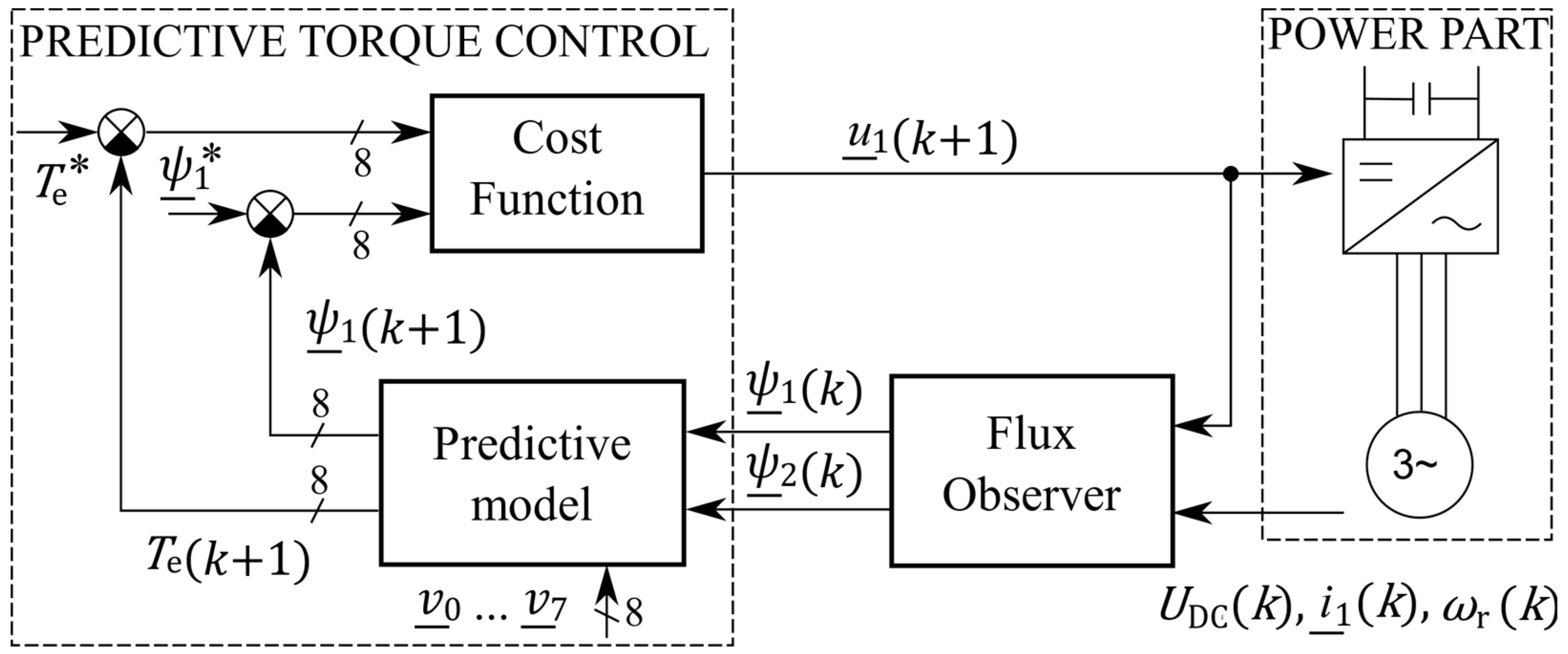
3.2. Predictive Torque Control Algorithm

Within a two-level voltage-source inverter, eight fundamental switching combinations corresponding to six active and two passive voltage space vectors can be generated. These voltage vectors form a feasible set for the predictive control inputs. The application of one of the vectors to the motor terminals influences the controlled quantities—the stator flux amplitude and the developed torque, in a specific way. The PTC aims to predict the effect of each voltage vector for the next sampling time. Furthermore, these effects are evaluated according to the predefined criteria by the so-called cost function. The most suitable candidate is then selected from the feasible set. The basic block diagram of the PTC of IM is depicted in Figure 5.
The PTC-regulated variables are the stator flux linkage vector amplitude and the electromagnetic torque. The stator flux linkage vector is predicted for each voltage vector using Euler discretization of the voltage model of the induction motor, i.e.,
ψ _ 1 ( k + 1 ) = ψ _ 1 ( k ) + T s u _ 1 ( n ) T s R 1 i 1 _ ( k ) .
The stator flux vector candidates for a star and delta winding configuration (stator resistance neglected) are depicted in Figure 6.
The torque prediction utilizes the current estimate for the next sampling time in the form
i _ 1 ( k + 1 ) = ( 1 + T s τ σ ) i _ 1 ( k ) + T s ( τ σ + T s ) R σ [ ( k r τ r k r j ω r ( k ) ) ψ _ 2 ( k ) + u _ 1 ( n ) ] .
For the rotor flux vector estimation, the Luenberger observer described in [28] is utilized. Finally, the predicted electromagnetic torque is calculated as
T e ( k + 1 ) = 3 2 p p | ψ _ 1 ( k + 1 ) × i _ 1 ( k + 1 ) | .
The cost function then evaluates the predicted flux amplitude and the developed torque as
g ( n ) = k CF | ψ 1 ( k + 1 ) ψ 1 | + | T e ( k + 1 )   T e | .
This weighting coefficient k CF determines whether more emphasis is put on achieving the reference flux or torque [6]. If the coefficient is selected too small, the flux amplitude will exhibit oscillations; on the other hand, too high value then increases the torque ripple [29]. These two extremes can cause significant current distortion. In this paper, the most common choice of k CF is used, which is defined as [25]
k CF = T n ψ 1 n .
For all the possible voltage vectors, the cost function (40) is calculated, which yields a set of numerical values. The voltage vector corresponding to the minimal value brings the system closest to the desired state. This vector is then kept at the motor’s terminals until the next sampling period.

4. Simulation and Experimental Results

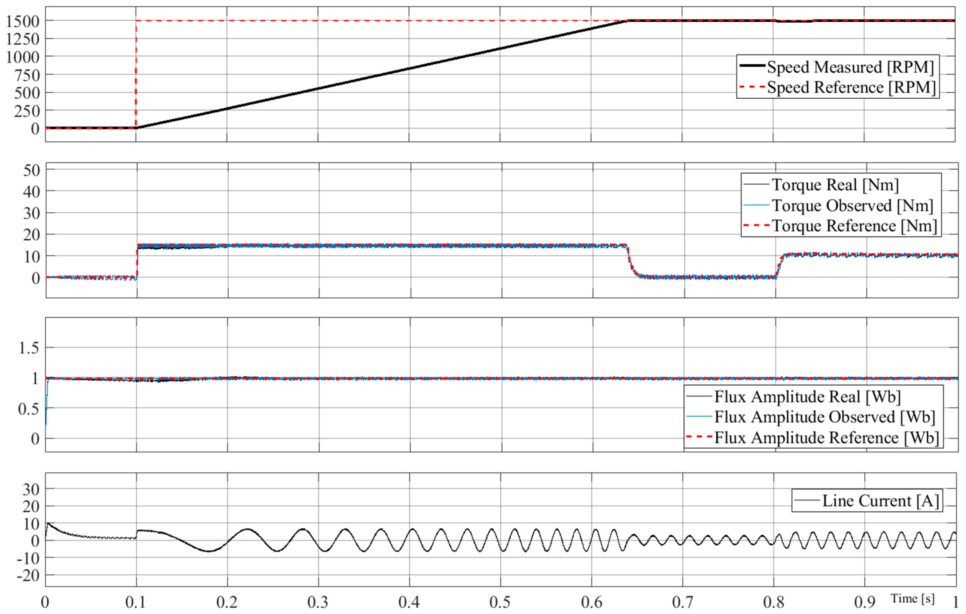
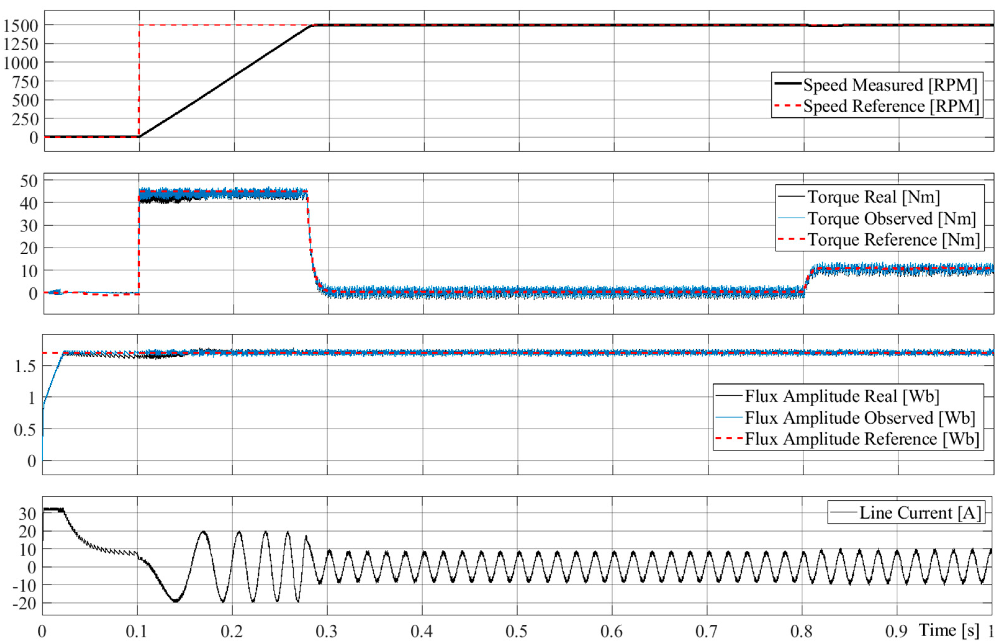
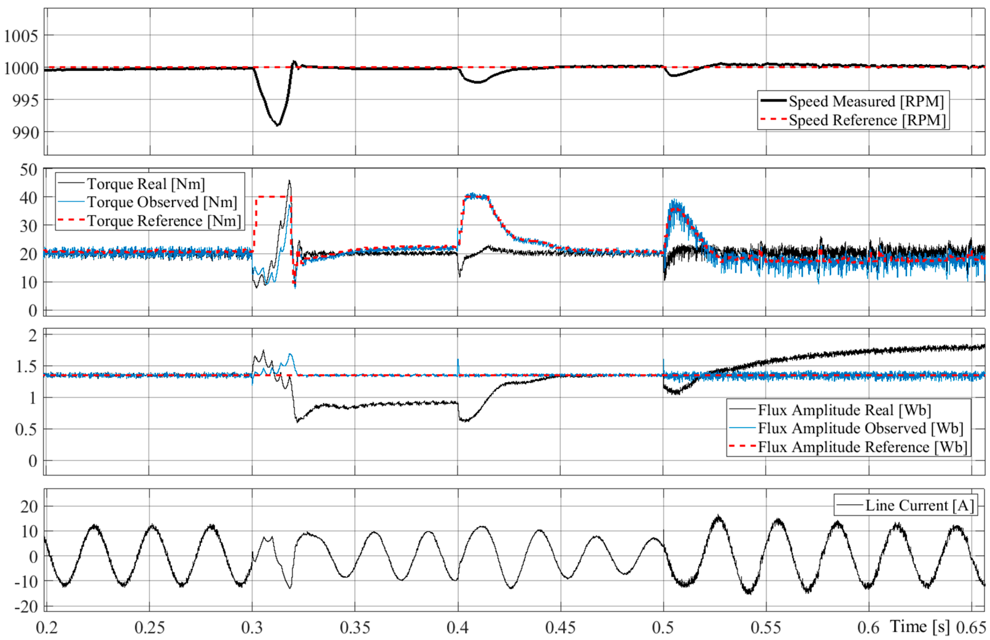
4.1. Simulation Results

The simulations were carried out in MATLAB/Simulink, where the mathematical model of IM drive controlled by the PTC algorithm with switchable delta-star topology both in the control model and machine model was created. The IM model’s step size was set to 10 µs and the control loop’s discrete step to 50 µs. The machine model parameters are given in Table A1 in Appendix B.
Figure 7 and Figure 8 show the startup of the motor connected to the star and delta, respectively, from 0 to 1500 RPM. The reference stator flux in the delta configuration was set to 1.7 Wb. Following Section 3.1, the stator flux in the star configuration had to be set to 1 Wb; otherwise, the drive would not be able to reach the reference speed. The speed controller torque limit in the star connection was set to one-third of the torque limit in the delta connection, where it represented 125 % of the nominal torque. Due to the flux and torque limitations in the star connection, the startup was faster for a delta winding configuration. However, in both cases, the control model’s estimated values coincided well with the actual values because the actual winding topology was respected in the control model.
Figure 9 demonstrates the consequences of not respecting the winding topology in the control algorithm. If the control system is not adjusted to the winding configuration, then the machine operates either in an under-excited or over-excited state, and the estimated torque and flux do not agree with the actual ones.
A graphical comparison of the torque, flux, and current ripple during an online winding changeover is depicted in Figure 10. The reference speed, flux, and load torque were set to 1000 RPM, 1.35 Wb, and 20 Nm, respectively. The figure clearly shows that the ripple of the IM quantities was significantly reduced in the star connection. A quantitative comparison of the current ripple in a star and delta configuration in terms of THD will be presented in the next section, which is dedicated to experimental results.

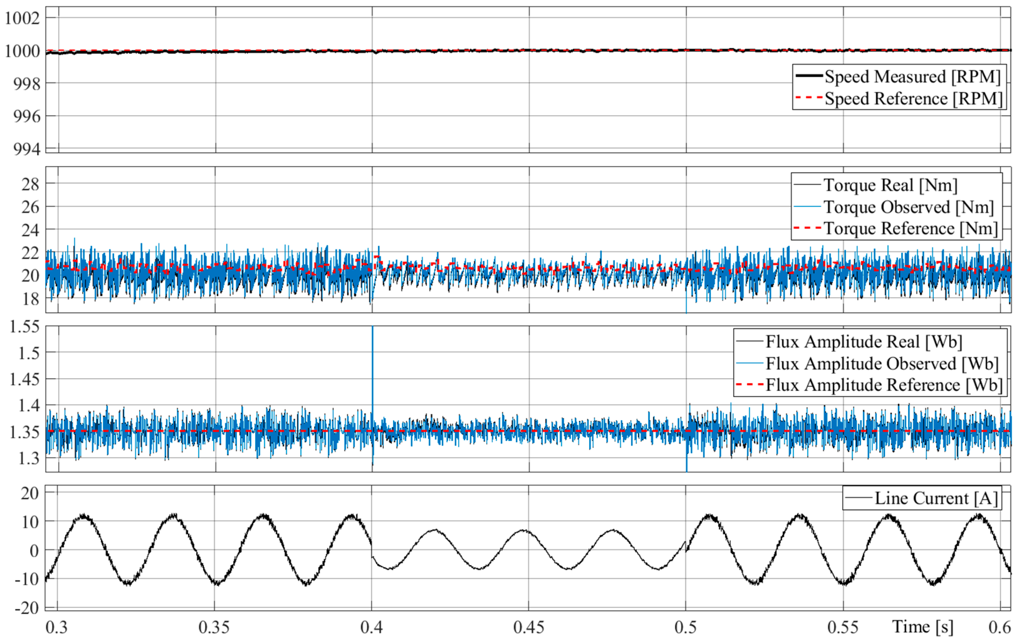
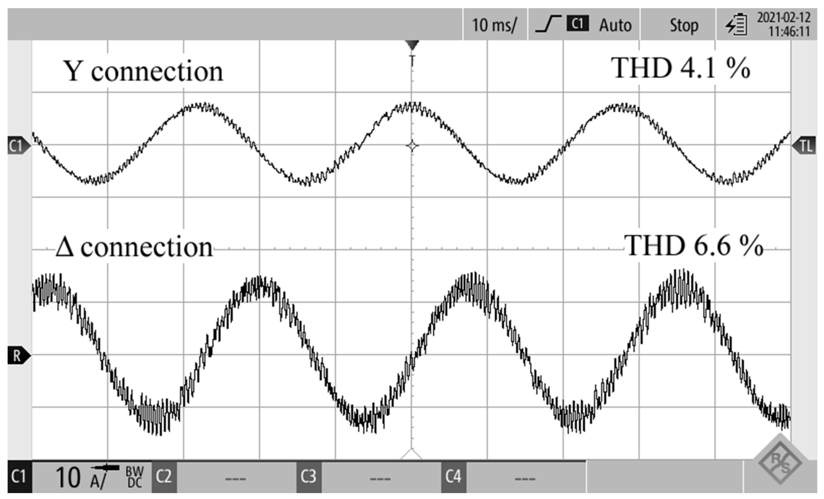
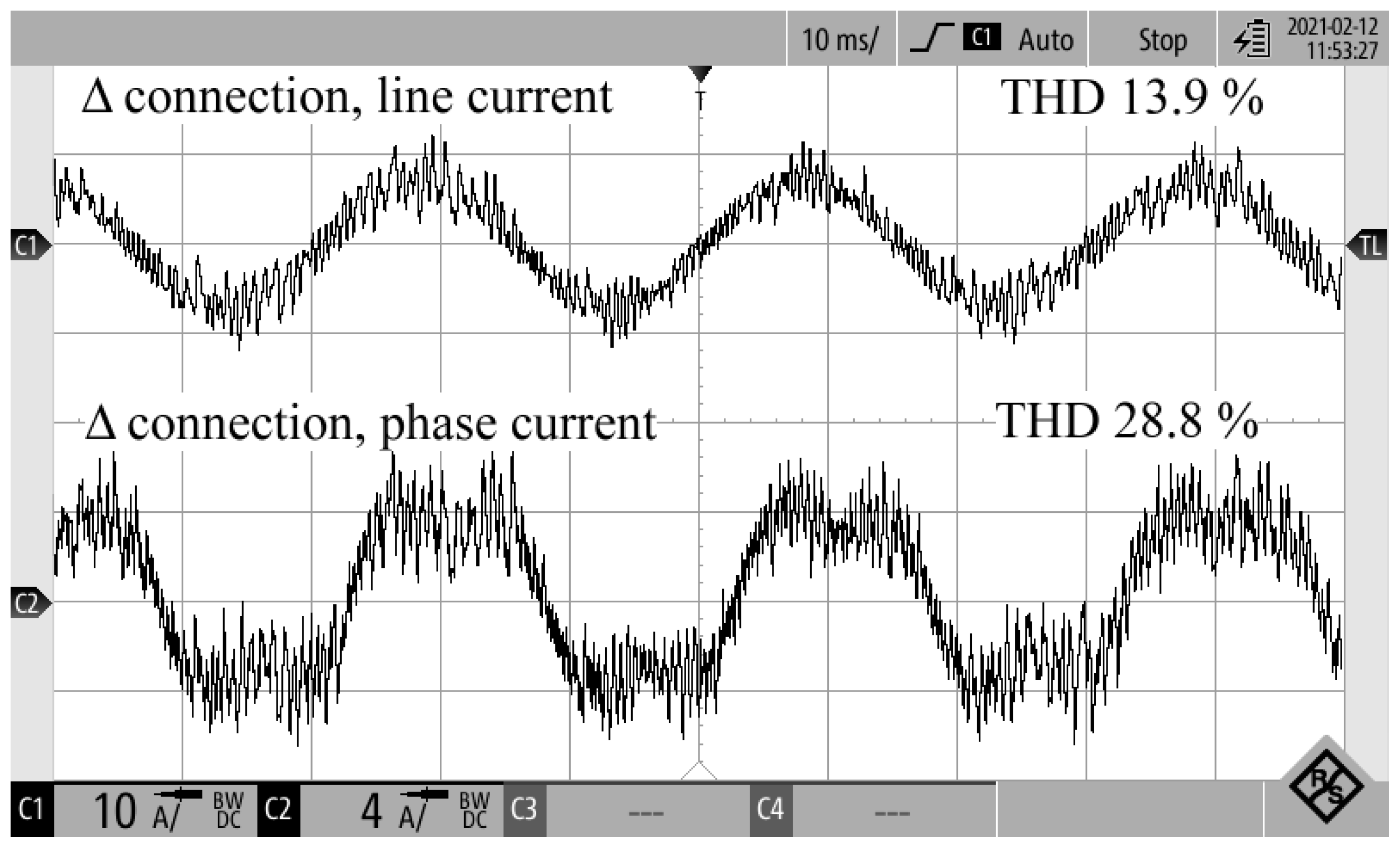
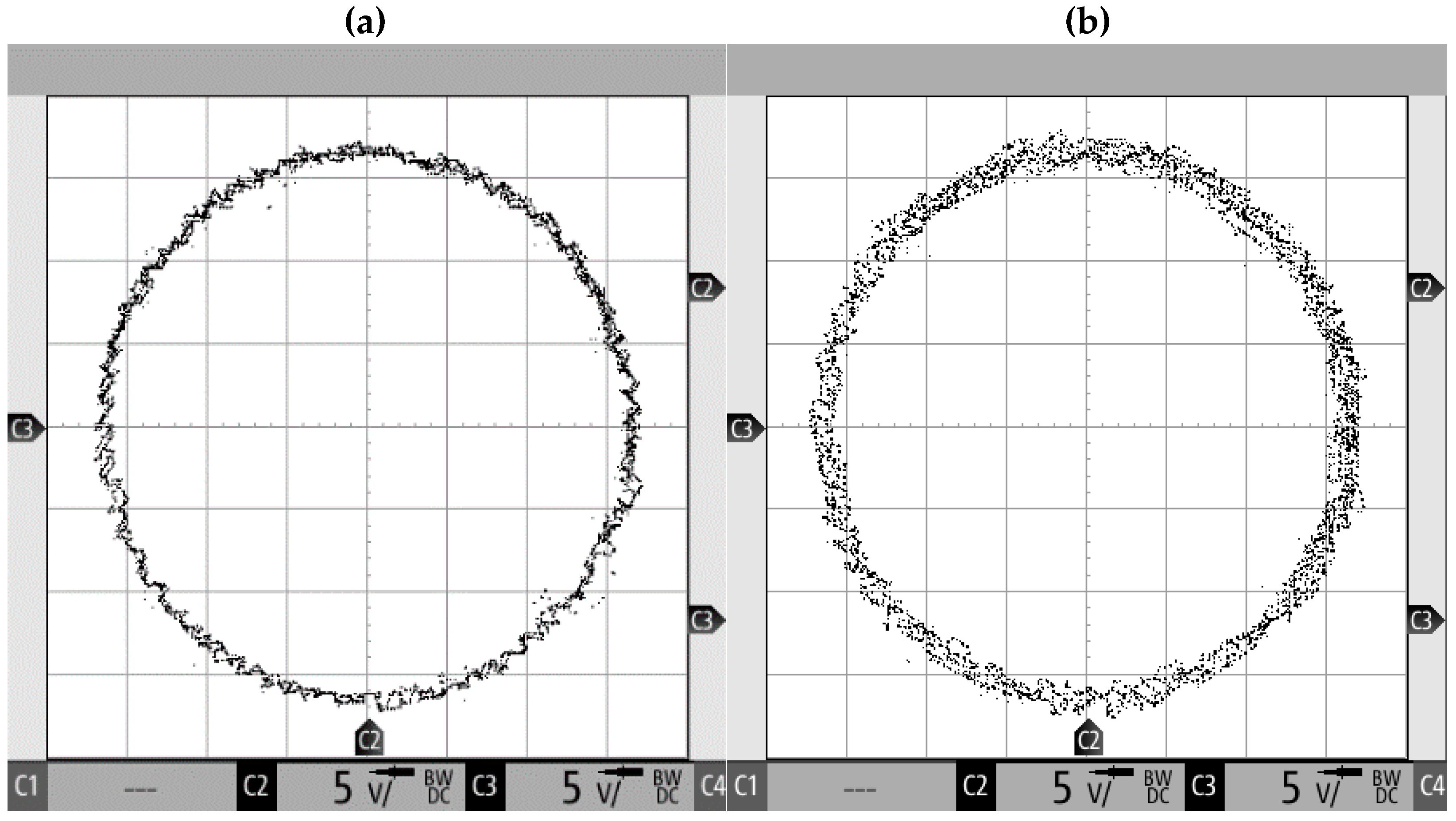
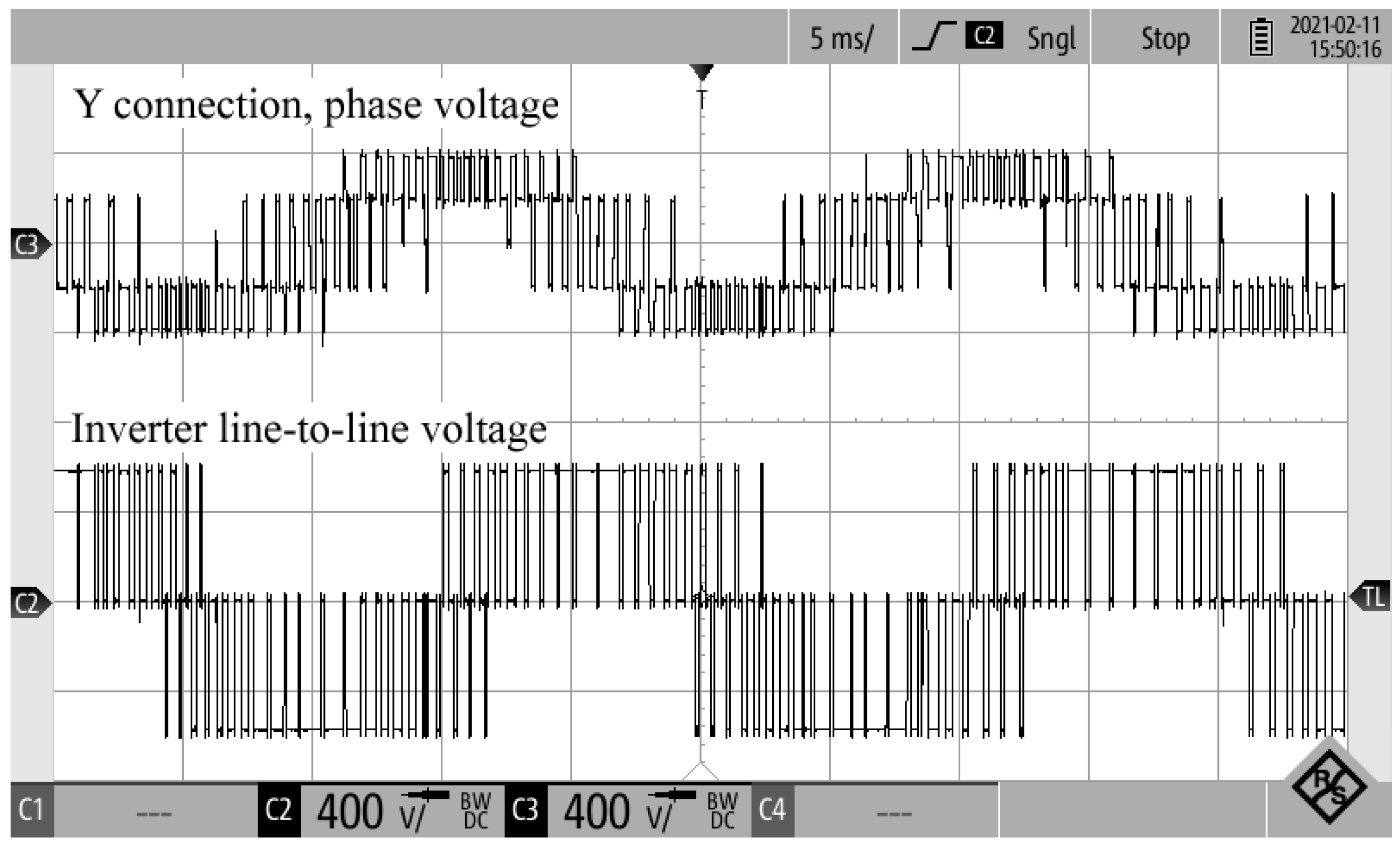
4.2. Experimental Results
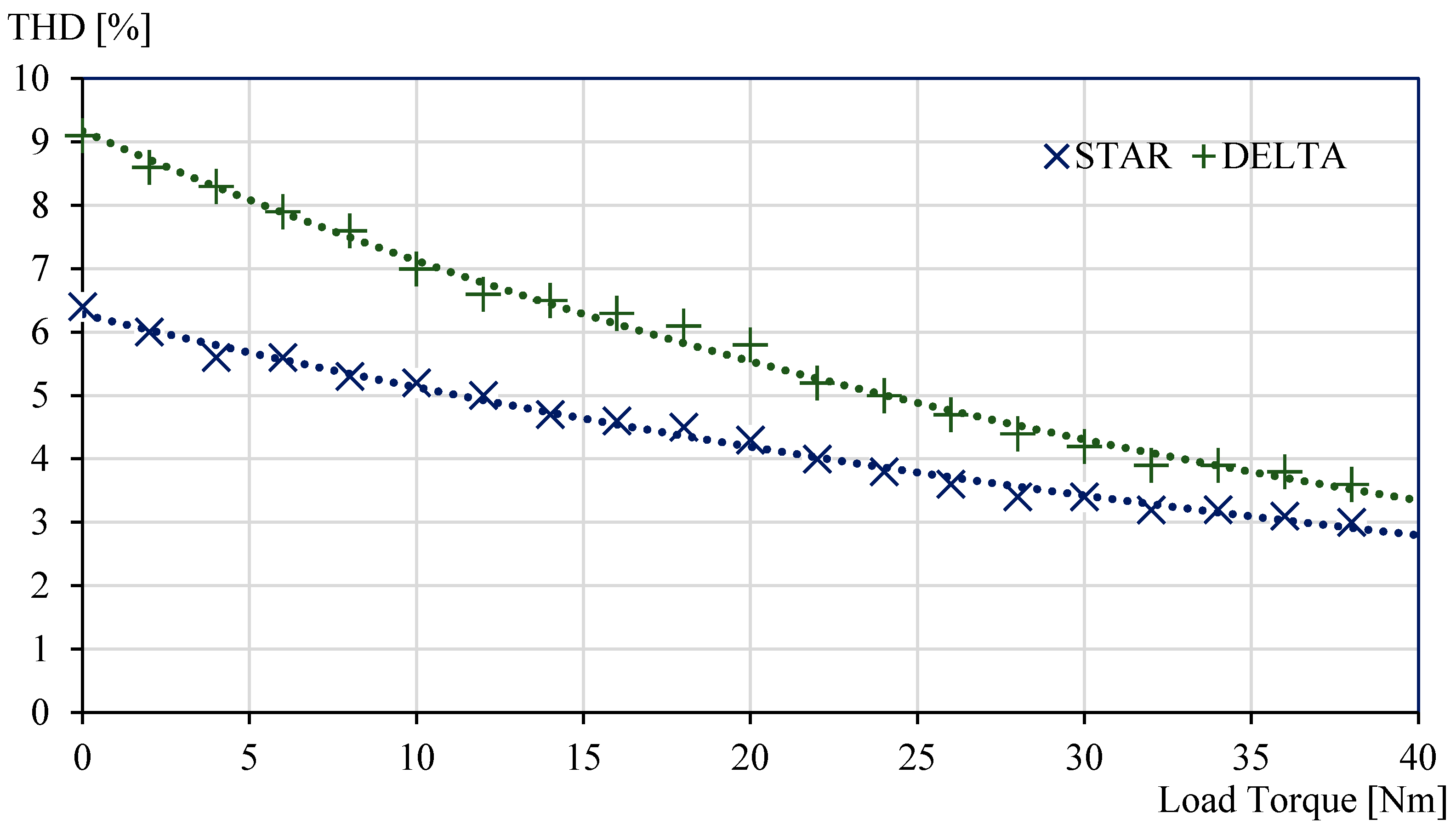
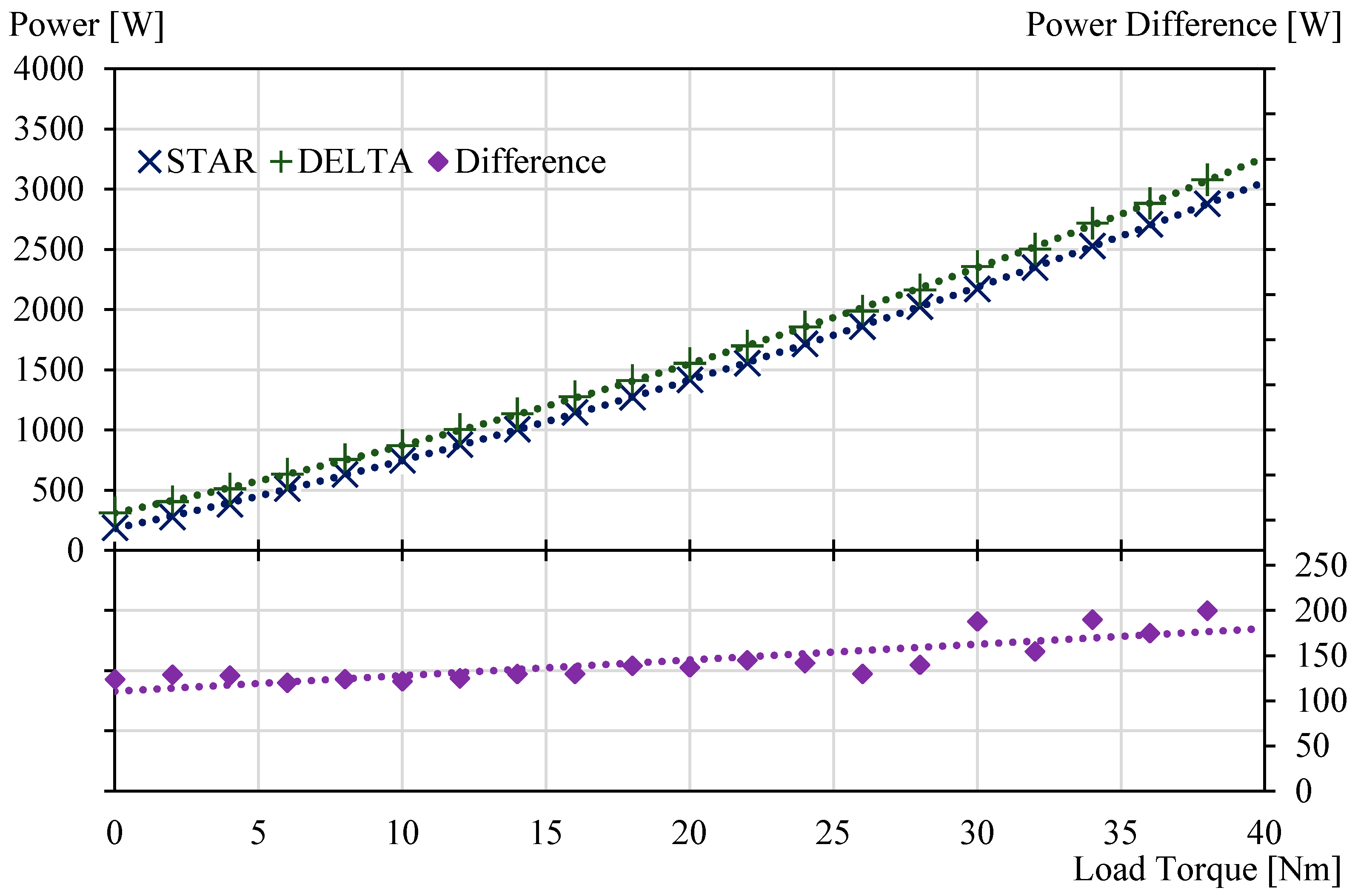
The experiments were conducted on a laboratory drive consisting of a 5.5-kW four-pole induction motor, three-phase IGBT inverter, diode rectifier, dSPACE DS1103 control platform, and a loading dynamometer. The nameplate data and the used machine model parameters are given in Table A1 in Appendix B. The sampling time of the control algorithm was set to 50 µs. Since the used PTC does not utilize a modulator, the transistors’ switching frequency was not constant, averaging around 2 kHz.
Table 2 shows a detailed comparison of current THD and electric power consumption for a delta and star winding connection. The input electric power was measured by NORMA 4000. The current THD was obtained from oscilloscope R&S RTH1004 using the current probe Tektronix A622. The THD was calculated as the ratio between the root mean square (RMS) of all distortion products (i.e., all the harmonics except the fundamental one) and the signal’s total RMS.
According to Table 2, the star-connected machine exhibited lower current THD in all achievable operating points, leading to lower power consumption. The difference grows with increasing flux reference and decreasing load.
Figure 11 and Figure 12 show the plotted dependence of the line current THD and consumed power, respectively, for the speed 500 RPM and reference stator flux 1.7 Wb. The THD difference decreased with increasing load, while the power difference increased slightly with the load. The saved power varied between 120 and 200 W, with an average value of approximately 145 W. The reason the THD decreased with increasing load is that the ratio of passive and active voltage vectors and their distribution differed at various loads. As for the power differences, it was expected that the most significant portion of the saved energy comes from the reduced iron losses that were THD-dependent [12,30] (distorted currents create distorted flux density distribution in the iron core). Even when substantial circulating currents were present, the contribution of the ohmic losses was expected to be less significant (in the range of Watts units).
An oscillogram showing the comparison of the line currents for a delta and star connection and operating point 1000 RPM, 1 Wb, and 15 Nm is depicted in Figure 13. The line current distortion was, visually and in THD, more significant in the delta-connection.
Figure 14 then compares the line and phase current of a delta-connected machine for the speed of 1000 RPM, stator flux 1.7 Wb, and load torque 0 Nm. There is a third harmonic in the inverter line-to-line voltage, which can circle in the delta-connected winding. This explains the differences between the line and phase currents THD in Table 2. However, it is worth noticing that the third time harmonics in the phase currents of a symmetrically wound machine cannot create a space vector and contribute to the air-gap flux.
Figure 15 shows an XY chart of the estimated stator flux linkage vector in the stationary α β coordinate system for a star and delta winding configuration. The oscillograms were obtained using a digital/analog converter of the dSpace platform. It was evident that in the case of the delta winding configuration, the algorithm operated with more distorted flux.
Figure 16 compares the motor phase voltage of a star-connected machine and the inverter line-to-line voltage (i.e., the motor phase voltage when the machine is delta-connected). In the case of star connection, the phase voltage took values ± 2 / 3 U DC , ± 1 / 3 U DC and 0 V, while in the delta connection it took ± U DC and 0 V. The higher instantaneous peak phase voltage in the delta connection was the leading cause of the higher current and, consequently, flux and torque distortion.

5. Discussion

In this paper, it was shown that the current and torque ripple of a nominally delta-connected machine can be decreased by utilizing a simple delta-star changeover technique that is commonly used to extend the base-speed region, efficiency, and power factor of IM drives. Since almost all papers dealing with the control of three-phase AC machines silently assumed that the machine winding is star connected, this paper also analyzes necessary modifications in the transformation of the measured currents of a delta-connected machine along with the differences in the inverter voltage vectors and their reconstruction. Another theoretical analysis presented in the paper was focused on the constraints that are imposed on the flux, speed, and torque control after the winding changeover from delta to star.
To realize the proposed approach, it is essential to respect the actual machine winding connection in the control algorithm. It was shown in simulations that not respecting the winding topology leads to inaccurate flux and torque estimation. If the algorithm supposes a delta winding connection and the machine is star-connected, then the motor operates in an under-excited state, with the actual stator flux being approximately 3 times smaller than the reference one. On the other hand, if the algorithm supposes a star-connected winding and the machine is delta-connected, then the motor operates in an over-excited state, with the actual stator flux being approximately 3 times higher than the reference one.
The experiments were predominantly focused on validating the proposed method by the analysis of the current THD and consumed electric power in multiple drive operating points. It was confirmed that if the operating point is achievable in both winding configurations, then the switchover to star leads to reduced current THD and less consumed power. The THD reduction was particularly significant at light mechanical loads.
The authors’ future research will focus on defining suitable conditions for the online winding changeover to maximize the power savings. Another important task will be to develop an approach that will ensure that the actual transition, either with a mechanical contactor or semiconductor switch, is as smooth as possible.

Author Contributions

Conceptualization, O.L.; methodology, O.L.; software, P.K. (Pavel Karlovský); validation, O.L. and P.K. (Pavel Karlovský); formal analysis, O.L.; investigation, O.L.; resources, O.L. and P.K. (Pavel Karlovský); data curation, P.K. (Pavel Karlovský); writing—original draft preparation, O.L. and P.K. (Pavel Karlovský); writing—review and editing, J.B. and P.K. (Pavel Kobrle); visualization, O.L.; supervision, J.B.; project administration, O.L.; funding acquisition, P.K. (Pavel Kobrle). All authors have read and agreed to the published version of the manuscript.

Funding

This research was funded by the Student Grant Agency of the Czech Technical University in Prague under grant No. SGS21/116/OHK3/2T/13.

Institutional Review Board Statement

Not applicable.

Informed Consent Statement

Not applicable.

Data Availability Statement

Data is contained within the article.

Conflicts of Interest

The authors declare no conflict of interest.

Nomenclature

i _ 1 stator current space vector [A]
u _ 1 stator voltage space vector [V]
v _ κ ( Y ) , v _ κ ( Δ ) basic voltage vectors in star/delta connection [V]; κ {   1 ,   2 ,   3 ,   4 ,   5 ,   6 }
ψ _ 1 , ψ _ 2 stator and rotor flux linkage space vectors [Wb]
L 1 , L 2 , L m stator, rotor, and magnetizing inductance [H]
R 1 , R 2 , R σ stator, rotor, and auxiliary model resistance [Ω]; R σ = R 1 + R 2 k r 2
S a , S b , S c control signals for the corresponding inverter leg [-]
T e electromechanical torque [Nm]
T lim ( Y ) , T lim ( ) torque command limits in star and delta winding configurations [Nm]
T s sampling time [s]
U DC , U max DC-link voltage, maximum voltage obtainable from the inverter [V]
U n nominal machine line-to-line voltage [V]
f n nominal machine supply frequency [Hz]
i 1 d , I 1 d ( n ) flux-producing current, nominal flux-producing current [A]
i 1 α , i 1 β stator current vector components in stator-fixed α β system [A]
i a , i b , i c stator phase currents [A]
i La , i Lb , i Lc stator line currents [A]
k CF cost function weighting coefficient [Nm·Wb−1]
k r auxiliary model coefficient [-]; k r = L m / L 2
k scale flux-producing current scaling factor [-]
p p number of pole-pairs [-]
u a , u b , u c motor phase voltages [V]
u a 0 , u b 0 , u c 0 inverter phase voltages [V]
τ r , τ σ rotor time constant, auxiliary time constant [s]; τ r = L 2 / R 2 , τ σ = σ L 1 / R σ
ψ 1 ( Y ) , ψ 1 ( Δ ) stator flux linkage vector amplitudes in star and delta [Wb]
ψ 1 n ( Y ) , ψ 1 n ( ) nominal stator flux linkage vector amplitudes in star and delta [Wb]
ω r electrical rotor speed [rad·s−1]
a complex rotational operator [-]; a = exp ( 2 π / 3 )
K Clarke’s transformation constant [-]
σ leakage factor [-], σ = 1 L m 2 / ( L 1 L 2 )

Appendix A

The well-known relationship between the stator and rotor flux linkage vectors is given by
ψ _ 1 = L m L 2 ψ _ 2 + σ L 1 i _ 1 .
Considering a d q rotor flux linkage vector-oriented reference frame ( ψ 2 q = 0 ) and a steady-state operation ( ψ 2 d = L m i 1 d ), the magnitude of the stator flux linkage vector can be written as
ψ 1 = L 1 2 σ 2 i 1 q 2 + ( L m 2 i 1 d L 2 + L 1 σ i 1 d ) 2 .
The q -axis current component can be calculated using the stator current vector magnitude:
i 1 q = i 1 2 i 1 d 2 .
Substituting (A3) into (A2) yields
ψ 1 = L 1 2 σ 2 i 1 2 + L m 2 L 2 2 ( L m 2 + 2 L 1 L 2 σ ) i 1 d .

Appendix B

Table A1. Induction motor nameplate data and mathematical model parameters.
Nameplate DataMathematical Model Parameters
Nominal power5.5 kWStator resistance 2.53 Ω
Nominal voltage380 VRotor resistance 2.62 Ω
Nominal current11.8 AStator inductance 0.3805 H
Nominal speed1430 min−1Rotor inductance 0.3805 H
Number of poles4Mag. inductance 0.3566 H
Winding connectionIron core resistance 835 Ω

References

  1. Casadei, D.; Profumo, F.; Serra, G.; Tani, A. FOC and DTC: Two viable schemes for induction motors torque control. IEEE Trans. Power Electron. 2002, 17, 779–787. [Google Scholar] [CrossRef] [Green Version]
  2. Wang, F.; Mei, X.; Rodriguez, J.; Kennel, R.M. Model predictive control for electrical drive systems—An overview. CES Trans. Electr. Mach. Syst. 2017, 1, 219–230. [Google Scholar] [CrossRef]
  3. Zhang, Y.; Yang, H. Model Predictive Torque Control of Induction Motor Drives with Optimal Duty Cycle Control. IEEE Trans. Power Electron. 2014, 29, 6593–6603. [Google Scholar] [CrossRef]
  4. Wang, F.; Zhang, Z.; Mei, X.; Rodríguez, J.; Kennel, R.M. Advanced Control Strategies of Induction Machine: Field Oriented Control, Direct Torque Control and Model Predictive Control. Energies 2018, 11, 120. [Google Scholar] [CrossRef] [Green Version]
  5. Karlovsky, P.; Lettl, J. Induction Motor Drive Direct Torque Control and Predictive Torque Control Comparison Based on Switching Pattern Analysis. Energies 2018, 11, 1793. [Google Scholar] [CrossRef] [Green Version]
  6. Karamanakos, P.; Geyer, T. Guidelines for the Design of Finite Control Set Model Predictive Controllers. IEEE Trans. Power Electron. 2020, 35, 7434–7450. [Google Scholar] [CrossRef]
  7. Karamanakos, P.; Stolze, P.; Kennel, R.M.; Manias, S.; du Toit Mouton, H. Variable Switching Point Predictive Torque Control of Induction Machines. IEEE J. Emerg. Sel. Top. Power Electron. 2014, 2, 285–295. [Google Scholar] [CrossRef]
  8. Bhowate, A.; Aware, M.; Sharma, S. Synthetic Voltage Vector Selection Criteria in Predictive Torque Control for Performance Improvement of Three Phase Induction Motor Drive. In Proceedings of the 2019 10th International Conference on Power Electron and ECCE Asia (ICPE 2019—ECCE Asia), Busan, Korea, 27–30 May 2019; pp. 1263–1267. [Google Scholar]
  9. Karpe, S.R.; Deokar, S.A.; Dixit, A.M. Switching losses minimization and performance improvement of PCC and PTC methods of model predictive direct torque control drives with 15-level inverter. J. Electr. Syst. Inf. Technol. 2018, 5, 759–776. [Google Scholar] [CrossRef]
  10. Bándy, K.; Stumpf, P. Model Predictive Torque Control for Multilevel Inverter fed Induction Machines Using Sorting Networks. IEEE Access 2021, 9, 13800–13813. [Google Scholar] [CrossRef]
  11. Karlovsky, P.; Lipcak, O.; Bauer, J.; Lettl, J. Predictive Torque Control of Induction Motor with Integrated DC-Link Voltage Optimisation. IET Power Electron. 2020, 13, 3396–3406. [Google Scholar] [CrossRef]
  12. Karlovsky, P.; Lipcak, O.; Bauer, J. Iron Loss Minimization Strategy for Predictive Torque Control of Induction Motor. Electronics 2020, 9, 566. [Google Scholar] [CrossRef] [Green Version]
  13. Himabindu, T.; Teja, A.V.R.; Bhuvaneswari, G.; Singh, B. Simplified predictive torque control of an IM drive with efficient zero vector placement. In Proceedings of the 2017 IEEE 26th International Symposium on Industrial Electronics (ISIE), Edinburgh, UK, 19–21 June 2017; pp. 362–367. [Google Scholar]
  14. Geyer, T.; Quevedo, D.E. Performance of Multistep Finite Control Set Model Predictive Control for Power Electronics. IEEE Trans. Power Electron. 2015, 30, 1633–1644. [Google Scholar] [CrossRef]
  15. Arif, A.; Baloch, N.; Ayub, M.; Kwon, B.-I. Wide-Speed Range Operation of PM Vernier Machines Using Wye and Wye-Delta Winding Configurations. IEEE Access 2020, 8, 194709–194718. [Google Scholar] [CrossRef]
  16. Atiq, S.; Lipo, T.A.; Kwon, B. Wide Speed Range Operation of Non-Salient PM Machines. IEEE Trans. Energy Convers. 2016, 31, 1179–1191. [Google Scholar] [CrossRef]
  17. Kume, T.; Swamy, M. A quick transition electronic winding changeover technique for extended speed ranges. In Proceedings of the 2004 IEEE 35th Annual Power Electron, Specialists Conference, Aachen, Germany, 20–25 June 2004; pp. 3384–3389. [Google Scholar]
  18. Wang, M.; Hsu, N.; Chiang, C.; Wang, S.; Shau, T. A novel changeover technique for variable-winding brushless DC motor drives. In Proceedings of the SICE Annual Conference 2010, Taipei, Taiwan, 18–21 August 2010; pp. 2650–2653. [Google Scholar]
  19. Kume, T.; Iwakane, T.; Sawa, T.; Yoshida, T.; Nagai, I. A wide constant power range vector-controlled AC motor drive using winding changeover technique. IEEE Trans. Ind. Appl. 1991, 27, 934–939. [Google Scholar] [CrossRef]
  20. Swamy, M.M.; Kume, T.; Maemura, A.; Morimoto, S. Extended high-speed operation via electronic winding-change method for AC motors. IEEE Trans. Ind. Appl. 2006, 42, 742–752. [Google Scholar] [CrossRef]
  21. Shi, P.; Cui, X.; Zhu, L. A SCR-based switch-control strategy of delta/wye switchover for delta connected induction motors. In Proceedings of the 7th International Power Electron and Motion Control Conference, Harbin, China, 2–5 June 2012; pp. 2607–2611. [Google Scholar]
  22. Ferreira, F.J.T.E.; de Almeida, A.T.; Baoming, G.; Faria, S.P.; Marques, J.M. Automatic change of the stator-winding connection of variable-load three-phase induction motors to improve the efficiency and power factor. In Proceedings of the 2005 IEEE International Conference on Industrial Technology, Hong Kong, China, 14–17 December 2005; pp. 1331–1336. [Google Scholar]
  23. Ferreira, F.J.T.E.; de Almeida, A.T. Method for in-field evaluation of the stator winding connection of three-phase induction motors to maximize efficiency and power factor. IEEE Trans. Energy Convers. 2006, 21, 370–379. [Google Scholar] [CrossRef]
  24. Beleiu, H.G.; Maier, V.; Pavel, S.G.; Birou, I.; Pică, C.S.; Dărab, P.C. Harmonics Consequences on Drive Systems with Induction Motor. Appl. Sci. 2020, 10, 1528. [Google Scholar] [CrossRef] [Green Version]
  25. Rodriguez, J.; Cortes, P. Predictive Control of Power Converters and Electrical Drives; Wiley-IEEE Press: Hoboken, NJ, USA, 2012; 246p. [Google Scholar]
  26. Zhang, L.; Hu, Y.; Huang, W. Research on DTC Control Strategy of Induction Starter/generator System. In Proceedings of the 2005 International Conference on Electrical Machines and Systems, Nanjing, China, 27–29 September 2005; pp. 1528–1533. [Google Scholar]
  27. Zarri, L.; Mengoni, M.; Tani, A.; Serra, G.; Casadei, D.; Ojo, J.O. Control schemes for field weakening of induction machines: A review. In Proceedings of the 2015 IEEE Workshop on Electrical Machines Design, Control and Diagnosis (WEMDCD), Turin, Italy, 26–27 March 2015; pp. 146–155. [Google Scholar]
  28. Gacho, J.; Zalman, M. IM Based Speed Servodrive with Luenberger Observer. J. Electr. Eng. 2016, 61, 149–156. [Google Scholar] [CrossRef] [Green Version]
  29. Cortes, P.; Kouro, S.; La Rocca, B.; Vargas, R.; Rodriguez, J.; Leon, J.I.; Vazquez, S.; Franquelo, L.G. Guidelines for weighting factors design in Model Predictive Control of power converters and drives. In Proceedings of the 2009 IEEE International Conference on Industrial Technology, Churchill, VIC, Australia, 10–13 February 2009; pp. 1–7. [Google Scholar]
  30. Zhang, D.; An, R.; Wu, T. Effect of voltage unbalance and distortion on the loss characteristics of three-phase cage induction motor. IET Electr. Power Appl. 2018, 12, 264–270. [Google Scholar] [CrossRef]
Figure 1. Three-phase winding: (a) star connection; (b) delta connection.
Applsci 11 02863 g001
Figure 2. Inverter supplying a delta-connected machine.
Applsci 11 02863 g002
Figure 3. Six active voltage vectors in the stator-fixed α β system: (a) delta-connected winding; (b) star-connected winding.
Applsci 11 02863 g003
Figure 4. Equivalent circuit of the inverter and delta-connected load.
Applsci 11 02863 g004
Figure 5. Basic block diagram of the induction motor predictive torque control.
Applsci 11 02863 g005
Figure 6. Stator flux linkage vector candidates (stator resistance neglected): (a) star-connected winding; (b) delta-connected winding.
Applsci 11 02863 g006
Figure 7. Startup of the motor from 0 to 1500 RPM—star-connected winding.
Applsci 11 02863 g007
Figure 8. Startup of the motor 0 to 1500 RPM—delta-connected winding.
Applsci 11 02863 g008
Figure 9. Online change of the winding topology—motor/predictive torque control (PTC): delta/delta (0.2–0.3 s), star/delta (0.3–0.4 s), star/star (0.4–0.5 s), delta/star (0.5–0.65 s).
Applsci 11 02863 g009
Figure 10. Online change of the winding topology both in the motor model and control model—delta (0.3–0.4 s), star (0.4–0.5 s), delta (0.5–0.6 s).
Applsci 11 02863 g010
Figure 11. Line current THD for a star and delta; reference speed 500 RPM, reference stator flux 1.7 Wb.
Applsci 11 02863 g011
Figure 12. Consumed electric power for a star and delta; reference speed 500 RPM, reference stator flux 1.7 Wb.
Applsci 11 02863 g012
Figure 13. Line current comparison for a star and delta winding connection; reference speed 1000 RPM, reference stator flux 1 Wb, load torque 15 Nm.
Applsci 11 02863 g013
Figure 14. Line and phase current comparison for a delta winding connection; reference speed 1000 RPM, reference stator flux 1.7 Wb, load torque 0 Nm.
Applsci 11 02863 g014
Figure 15. XY chart of the estimated stator flux linkage vector in the stationary α β coordinate system; reference speed 750 RPM, reference stator flux 1.7 Wb, load torque 0 Nm: (a) star-connected winding; (b) delta-connected winding.
Applsci 11 02863 g015
Figure 16. Comparison of the motor phase voltage in a star configuration with the inverter line-to-line voltage (i.e., the phase voltage for a delta configuration); DC-link voltage 560 V.
Applsci 11 02863 g016
Table 1. Switching combinations and corresponding voltage vectors for delta-connected machine.
Switching Combination u a u b u c Corresponding Phase Voltage Vector ( K = 2 / 3 )
000000 v _ 0 ( Δ ) = 0
100 + U DC 0 U DC v _ 1 ( Δ ) = 2 3   U DC e j π 6
1100 + U DC U DC v _ 2 ( Δ ) = 2 3   U DC e j π 2
010 U DC + U DC 0 v _ 3 ( Δ ) = 2 3   U DC e j 5 π 6
011 U DC 0 + U DC v _ 4 ( Δ ) = 2 3   U DC e j 5 π 6
0010 U DC + U DC v _ 5 ( Δ ) = 2 3   U DC e j π 2
101 + U DC U DC 0 v _ 6 ( Δ ) = 2 3   U DC e j π 6
111000 v _ 7 ( Δ ) = 0
Table 2. Comparison of current the total harmonic distortion (THD) and input electric power in multiple operating points for a delta and star winding connections.
Rotational Speed [RPM]Load Torque [Nm]Current THD—Y
[%]
Input Electric Power—Y
[W]
Line Current THD—∆
[%]
Phase Current THD—∆
[%]
Input Electric Power—∆
[W]
Difference in Power [W]
10
(1.7 Wb)
0- 199- 1- 118283
15- 1227- 1- 1362135
30- 1648- 1- 1874226
37- 1935- 1- 11246311
100
(1.7 Wb)
0- 1118- 1- 121294
15- 1367- 1- 1478111
30- 1885- 1- 11072187
37- 11205- 1- 11440235
250
(1.7 Wb)
0- 1154- 1- 1270116
153.56324.510.4758126
302.713702.66.81550180
372.417852.86.52000215
500
(1.7 Wb)
05.81958.727.1324129
154.610656.716.31196131
303.421874.59.52387200
373.228303.59.52980150
750
(1.7 Wb)
08.315614.218.8278122
154.215025.98.11651149
302.933004.49.03500200
373.744154.411.54640225
1000
(1.3 Wb)
011.519419.222.4310116
155.518758.7102016141
303.741405.710.64350210
37- 2- 25.311.15750- 2
1250
(1 Wb)
015.520827.728327119
106159010.710.91725135
203.835156.510.83725210
1250
(1.3 Wb)
30- 2- 26.011.75170- 2
37- 2- 25.711.66700- 2
1430
(1 Wb)
013.624225.926.5355113
58.591016.016.51035125
105.3178510.110.31925140
154.227807.39.52945165
1430
(1.7 Wb)
20- 2- 29.015.93620- 2
30- 2- 27.212.45385- 2
37- 2- 26.411.36720- 2
1 Below the oscilloscope resolution. 2 The operating point could not be reached.
Publisher’s Note: MDPI stays neutral with regard to jurisdictional claims in published maps and institutional affiliations.

