Article

Seven Level Voltage Source Converter Based Static Synchronous Compensator with a Constant DC-Link Voltage

by
L. Narayana Gadupudi
1,
Gudapati Sambasiva Rao
2,
Ramesh Devarapalli
3 and
Fausto Pedro García Márquez
4,*
1
Department of Electrical and Electronic Engineering, Acharya Nagarjuna University, Guntur 522510, India
2
Department of Electrical and Electronic Engineering, R.V.R. & J.C. College of Engineering, Guntur 522019, India
3
Department of Electrical Engineering, B.I.T. Sindri, Dhanbad 828123, India
4
Ingenium Research Group, University of Castilla-La Mancha, 13071 Ciudad Real, Spain
*
Author to whom correspondence should be addressed.
Appl. Sci. 2021, 11(16), 7330; https://doi.org/10.3390/app11167330
Submission received: 7 May 2021 / Revised: 4 August 2021 / Accepted: 5 August 2021 / Published: 9 August 2021

Abstract

:
Flexible alternating current transmission system (FACTS) controllers are important to enhance the quality of power in power systems. The stability of a system is achieved via a FACTS device (a Static Synchronous Compensator (STATCOM)). This paper aims to control the losses in the transmission system during peak energy demand circumstances with minimal losses in the economical and functional efficiency of the system. The STATCOM operation of a seven level voltage source converter (VSC) with binary-weighted transformers is proposed for controlling the reactive power variations and terminal voltage changes at dynamic circumstances in the transmission system. The STATCOM is operated at 132 kV and is a 50 Hz AC system with a single DC-Link capacitance and two VSC power circuits. Each VSC circuit consists of three H-bridges with specific switching angle control in order to achieve low total harmonic distortion at the fundamental frequency. The coupled control circuit phenomenon is imperative for computing the switching angle for a stable performance. The dynamic functional improvement efficiency is harvested with a minimum number of switches and transformers used in high voltage and high-power applications. The number of switches, transformers, and capacitors for 132 kV are optimized with a proposed STATCOM operation in seven level VSC with binary-weighted transformers. The simulated results prove that the proposed model significantly improved system performance and stability.

1. Introduction

The role that flexible alternating current transmission system (FACTS) devices play in peak voltages and at high-power applications is significant to achieving reactive power variations and sustaining a system voltage profile. The transmission lines are key parts in electrical engineering to transmit electrical power and terminal voltage for all electrical appliance usages. Meanwhile, the control of electrical losses in the transmission system remains a major challenge, and FACTS controllers have fulfilled this requirement. A FACTS device (the static synchronous compensator (STATCOM)) is being used to control the losses in terms of reactive power variations and terminal voltage changes in the system. The insulated gate bipolar transistors (IGBTs) based series H-bridges combination of STATCOM provides the consumption of reactive power in either direction of the system and to improve the system stability [1,2]. STATCOM has various models of multi-level converters for controlling reactive power. Voltage levels with direct current control techniques are able to harvest the system stability [3,4]. The STATCOM FACTS device is being used to control losses in terms of reactive power variation and terminal voltage changes in the system [5,6,7]. Combining bridges and optimizing the number of switches results in minimum switching losses and reduces the cost in medium voltage transmission lines [8,9,10]. The reference voltage, reference current, constant DC-Link, pulse width modulation (PWM), fast Fourier transform (FFT), and micro processor based control (MPC) control schemes of STATCOM provide predictive power changes at dynamic load conditions [11,12]. The stability of power in the transmission system has been settled by the hysteresis power regulations algorithm [13,14]. The system nominal voltage is established via the additive control of linear and nonlinear loads [15,16]. The voltage source converter (VSC) with PI controller limiters, decoupled link, hysteresis current, individual phase voltage, and current techniques is currently being implemented [17,18,19]. The bulk power rating of the high voltage direct current power transmission system’s performance is estimated via modular level converters with mean value and equivalent versions of submodule circuits [20]. The irregular power losses, switching losses, and dynamic efficiency are improved with a dual-loop control scheme of half-bridge multi level inverters based on STATCOM [21]. The series-parallel device combinations of hybrid switched multilevel converters, which are designed and implemented for high voltage as well as high power applications with improved performance [22]. Energy storage STATCOM of modular multi level converter methods are executed for high-level grid applications with a control flowchart to evaluate the dynamic performance [23]. Inverter-based STATCOM is operated to set the real power and reactive power boundaries by limiting the system current and voltage for grid utility conditions [24]. Model predictive control is adopted as a superior control mechanism in transmission systems to overcome the power interrupts. The optimized switching vector-based STATCOM has been established to upgrade power quality in the system [25]. A multi modular converter with quadrature voltage compensation control method is used to compute the circulating current and to control huge power imbalances in the system [26]. This paper describes performance transmission system stability improvement in high power and high voltage commercial application with minimum power switches in STATCOM.
The power variations are regulated and controlled by phase sequence algorithms [27,28,29]. Heavy loads (e.g., railway power grids and distribution networks) are being controlled with reactive current flows to obtain the constant voltage profile in demand of peak voltages as well as further voltages of power systems to comply with existing standards [30,31]. The current control limitations are derived to maintain the system reference voltages [32,33]. The FACTS controllers of a STATCOM have a very fast response and flexible operation at dynamic circumstances with prescribed capacity ranges. Therefore, the DC capacitor voltages remain ripple-free for the system [34,35,36]. The submodule capacitor of three-phase multi modular converter sequences is being investigated to improve the system voltage imbalances and to limit the compensation current under dynamic grid conditions [37]. The proposed energy-based multilevel multicell inverter has been implemented to provide negligible total harmonic distortion for power quality issues in microgrid applications [38]. A half-bridge modular multilevel converter with the nearest level control technique is deliberated to minimize the cell losses in balanced power conditions [39]. The over current of a multi-level converter based HVDC (high voltage direct current) transmission system is controlled via fault ride through a control algorithm for smooth system operations [40]. A full bridge submodule of a modular multilevel converter built high voltage direct current transmission system is operated with capacitor balancing methods to avoid the sudden system interrupts [41]. The dynamic oscillations of power issues in the transmission system are stabilized by steady developments of the one cycle control flowchart of diode clamped multi converters based STATCOM [42]. Three phase voltage converters based STATCOM determines the real power and reactive power variations, and regulates the power deviations for stable system voltage levels [43]. Transmission power issues and voltage disparity are dissolved by a super capacitor energy system built STATCOM to maintain an efficient system [44]. This paper analyses the dynamic load variation conditions and their low total harmonic distortion with smooth stable operations for large level systems.
A single DC-Link voltage of seven-level VSC-based STATCOM has been planned for reactive power regulation. It describes weighted transformer, minimum power electronic devices with coupled control methodology for stable voltage operations in a power system. The system indexed values of power, voltage, DC capacitor voltage, and firing angles are considered with satisfactory results, and the operations are discussed. The major contributions of the paper are detailed as follows:
  • A novel proposed seven level voltage source converter based STATCOM with single DC-link capacitor voltage is designed to enhance dynamic reactive power variations and stable voltage profile in a high-level voltage transmission system.
  • A novel seven level voltage source converter linked with binary weighted transformers is designed to meet the high rating voltages in a transmission system with low harmonic distortion.
  • In this proposed circuit, the switching angles are computed according to their levels of voltage source converters to maintain a constant voltage profile in the transmission system.
  • The proposed binary weighted transformer linked seven level voltage source converter is working with a decoupled algorithm to provide accurate results at various conditions of loads.
  • In this proposal circuit, the minimum number of power semiconductor switches and transformers are used to obtain better results than the conventional methods.
The rest of the paper is structured as follows: Section 2 deals with the new approach of voltage source converter based STATCOM operation and novel firing angle equation design; Section 3 presents a decoupled control technique in order to regulate the reactive power changes and to maintain a stable system voltage profile; Section 4 shows the dynamic performance of STATCOM results; Section 5 details comparisons of this work; Section 6 concludes the proposed binary weighted transformer integrated seven level VSC based STATCOM performance.

2. STATCOM Configuration and Operation

The novelty of this paper is the presence of binary weighted transformers (1:1 & 2:1 turns ratio’s) integrated seven level VSC based STATCOM with a single DC-Link capacitance and firing angle equation (which is newly developed for VSC with a low total harmonic distortion (THD) value). The turns ratio of binary weighted transformers is 1:2:4:……2n−1, which is suitable for multilevel (like seven level, fifteen level, thirty-one level ……) VSC based STATCOM. The switching angles are designed for multilevel VSC based STATCOM from a novel firing equation with minimum THD. It can be implemented for various dynamic conditions of reactive power changes and system voltage changes. The performance of the seven level VSC based STATCOM is presented under different dynamic conditions with switching on inductive and capacitive loads.

2.1. Principle of Operation

The construction of a binary transformer with various voltage source converter STATCOM is conducted to obtain the voltage output waveforms of an AC converter with minimum harmonic content. These VSCs have one DC-link capacitance, H-bridges, and transformers used at 1:2:4:…:2n−1 turn ratios. The DC-link capacitance voltage is used to control the AC converter output voltage with the phase angle of the transmission system voltages as well as STATCOM output voltage. STATCOM output voltage is lower than the voltage of the system titular. Then, the reactive power is drawn from the transmission system. Meanwhile, STATCOM output voltage matches the system nominal voltage, which is greater than the reactive power injecting into the transmission system. The main advantage of these binary transformers with multilevel VSCs of a DC-Link capacitance voltages is their ability to accomplish the various voltage output waveforms, which are dissimilar to those of normal conventional voltage source converters.

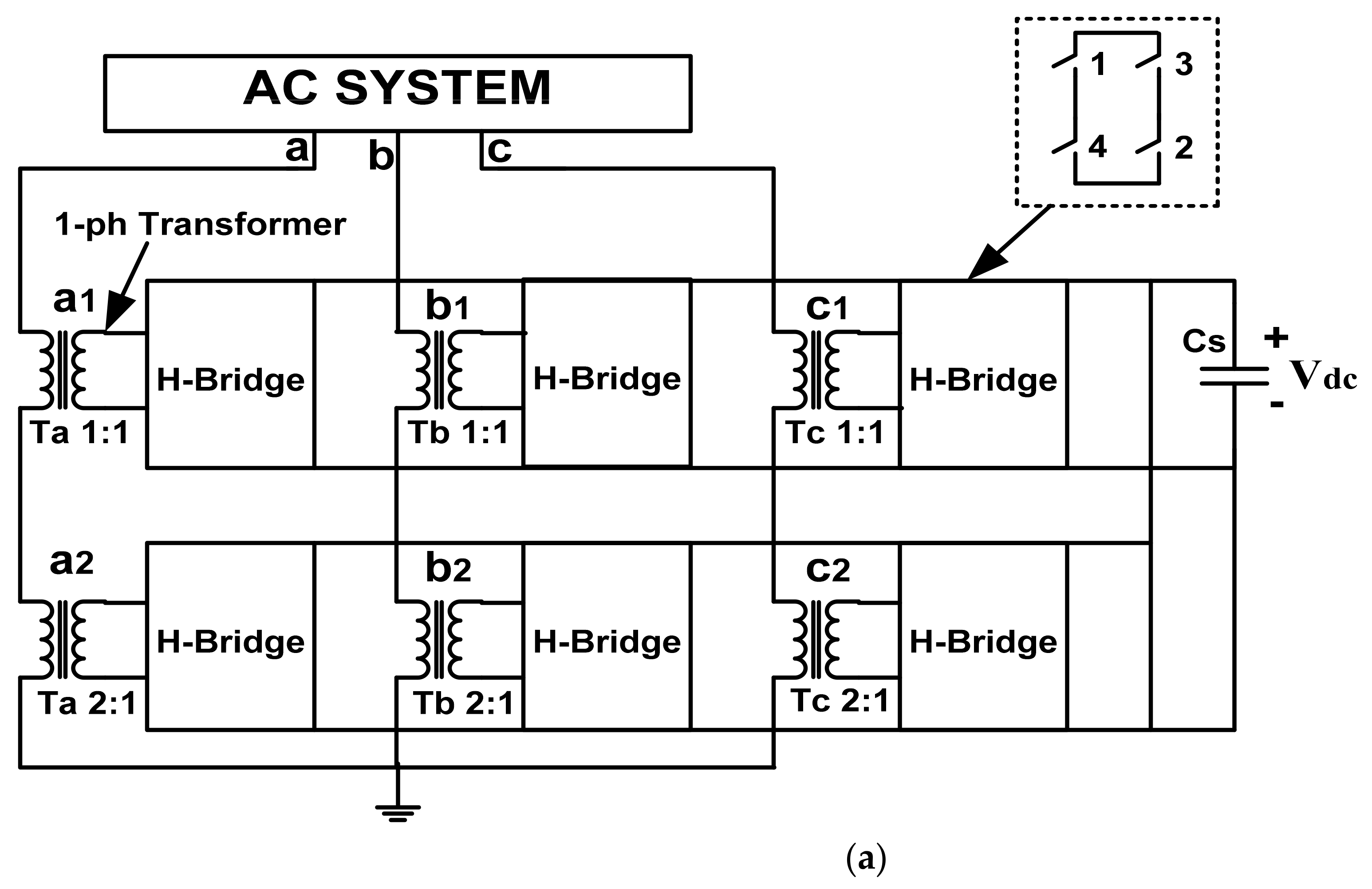
2.2. STATCOM Configuration with Seven Level VSC

The proposed configuration of a binary-weighted transformer integrated seven level VSC consists of self-commutating switching devices: GTOs or IGBTs, DC capacitance, AC reactance, interface transformer units and their controls. Figure 1a shows a STATCOM configuration with binary-weighted transformer-based seven level VSC. It has only one DC-Link capacitance and two three-phase modules, and each module consists of 3 H-bridges. The voltage source converters output is connected to transformers in 1:1 and 1:2 turn ratios.
Figure 1b shows that H-bridge switching pattern output waveforms are obtained in every level of a voltage source converter, and transformer 2 output voltage is twice the transformer 1 output voltage. The Equation (1) is a novel firing angle ‘ ’ generated for a multilevel voltage source converter (MLVSC). The firing angle is generated for seven Level VSC in the below-given procedure. The quarter sinusoidal waveform is equally divided into three levels of points and develops a staircase waveform. The firing angle is considered in advance of 0.5 to maintain the perfect levels of VSC with low THD values. The phase angle ‘ ’ is responsible for the reactive power control. The optimized firing pulses are chosen for the minimum THD value. The optimized firing pulses ‘α1’, ‘α2’, and ‘α3’ are estimated using Equation (1).
i = sin 1 i 0.5 3 ,   i = 1 , 2 , 3 .
where i = level of VSC and 3 is the maximum levels of VSC.
1 = 9.59 ° , 2 = 30 ° , 3 = 56.44 °
Figure 1c shows the harmonic spectrum of seven level VSC voltage output waveforms. The THD is 12.02% (a lower value than conventional VSC configurations).

3. Control Strategy Approach

The proposed control strategy deals with system voltages, currents, and powers of the transmission lines given in Figure 2.
The active and reactive powers of the system are given by Equations (2) and (3):
P S = V 1 d I 1 d + V 1 q I 1 q
Q S = V 1 d I 1 q V 1 q I 1 d
where V 1 d and V 1 q are the direct and quadrature of the system terminal voltages, the equations of which are given in Equations (4) and (5).
V 1 d = 2 3 V 1 a sin θ + V 1 b sin θ 120 °   +   V 1 c sin θ + 120 °
V 1 q = 2 3 V 1 a cos θ + V 1 b cos θ 120 °   +   V 1 c cos θ + 120 °
I 1 d and I 1 q are the direct and quadrature of the system terminal currents, given by Equations (6) and (7).
I 1 d = 2 3 I 1 a sin θ + I 1 b sin θ 120 °   +   I 1 c sin θ + 120 °
I 1 q = 2 3 I 1 a cos θ + I 1 b cos θ 120 °   +   I 1 c cos θ + 120 °
PLL is used to obtain sin θ   and cos θ in the voltage Equations (4) and (5), as well as the current Equations (6) and (7). The dq transformation is used for obtaining the direct axis (as well as the quadrature axis) of the voltages and currents in Equations (4)–(7).

3.1. DC-Link Voltage Controller

This DC-Link Voltage controller provides the direct axis reference current ‘ I 1 d * ’ by keeping the constant DC Voltage ‘ V 1 d c ’ with the reference DC Voltage ‘ V 1 d c * ’. The DC-Link Voltage controller is responsible for maintaining the constant DC Voltage ‘ V 1 d c ’ at the reference DC Voltage ‘ V 1 d c * ’. The proportional-integral (PI) controller is used for this purpose. The output of the PI controller accounts for the losses in the STATCOM, and it is considered to be the real power component of the current ‘ I 1 d * ’. The real power component of the current ‘ I 1 d * ’ is fed to to the decoupled controller. The DC-Link voltage controller maintains the DC-link voltage at the reference value using a small amount of active power transfer between the AC system and the DC–DC-Link of STATCOM. The low value active power flows to DC side to hold DC reference voltage, as expressed by Equation (8):
I 1 d * = K 1 P V 1 d c * V 1 d c + K 1 I V 1 d c * V 1 d c   d t

3.2. AC System Voltage Controller

This AC Voltage controller provides quadrature axis reference current ‘ I 1 q * ’ to keep constant AC system voltage ‘ V 1 t ’ with the reference AC system voltage ‘ V 1 t * ’. The quadrature axis reference current is connected to the coupled regulator for estimation of the phase angle and is expressed by Equation (9):
I 1 q * = K 1 P V 1 t * V 1 t + K 1 I V 1 t * V 1 t d t

3.3. Decoupled Current Regulator

The decoupled current regulator controls the active power variations (as well as the reactive power variations) in the transmission system. The reference currents of the direct axis and quadrature axis from the DC-Link controller and AC system terminal controller feed to internal current controllers and compute the reference converter voltages for the estimation of the phase angles of the VSC converters. The equations are represented by Equations (10) and (11):
V 1 c d * = V 1 c d K c P d I 1 d * I 1 d K c I d I 1 d * I 1 d   d t
V 1 c q * = V 1 c q K c P q I 1 q * I 1 q K c I q I 1 q * I 1 q   d t
where ‘ K c P d ’ and ‘ K c I d   ‘ are proportional and integral gains of the d-axis in Equation (10) and ‘ K c P q ’ and ‘ K c I q ’ are proportional and integral gains of the q-axis in Equation (11).

3.4. Estimation of Phase Angle

This calculation gives the DC capacitance reference voltage for stable real power in the transmission system. Equation (12) provides the phase angle ‘ δ * ’ (the differences between the AC terminal voltage and STATCOM AC output voltage), which is responsible for regulating the DC-Link Voltage of VSC. It is not impacted on THD but is impacted on a smoothing system voltage profile.
δ * = tan 1 V 1 c q * V 1 c d *

4. STATCOM Performance and Results

The transformer integrated seven level VSC based STATCOM was implemented and associated with a 132 kV, 50 Hz AC power system. The dynamic load progress of STATCOM was estimated with reactive power changes at a nominal point ‘ Q S * ’, and the terminal voltage changes at nominal point ‘ v t * ’; then, quadrature current ‘ I 1 q * ’ was evaluated for stable operation of the system with minimum harmonic distortion. The system parameters have been mentioned in Appendix A.
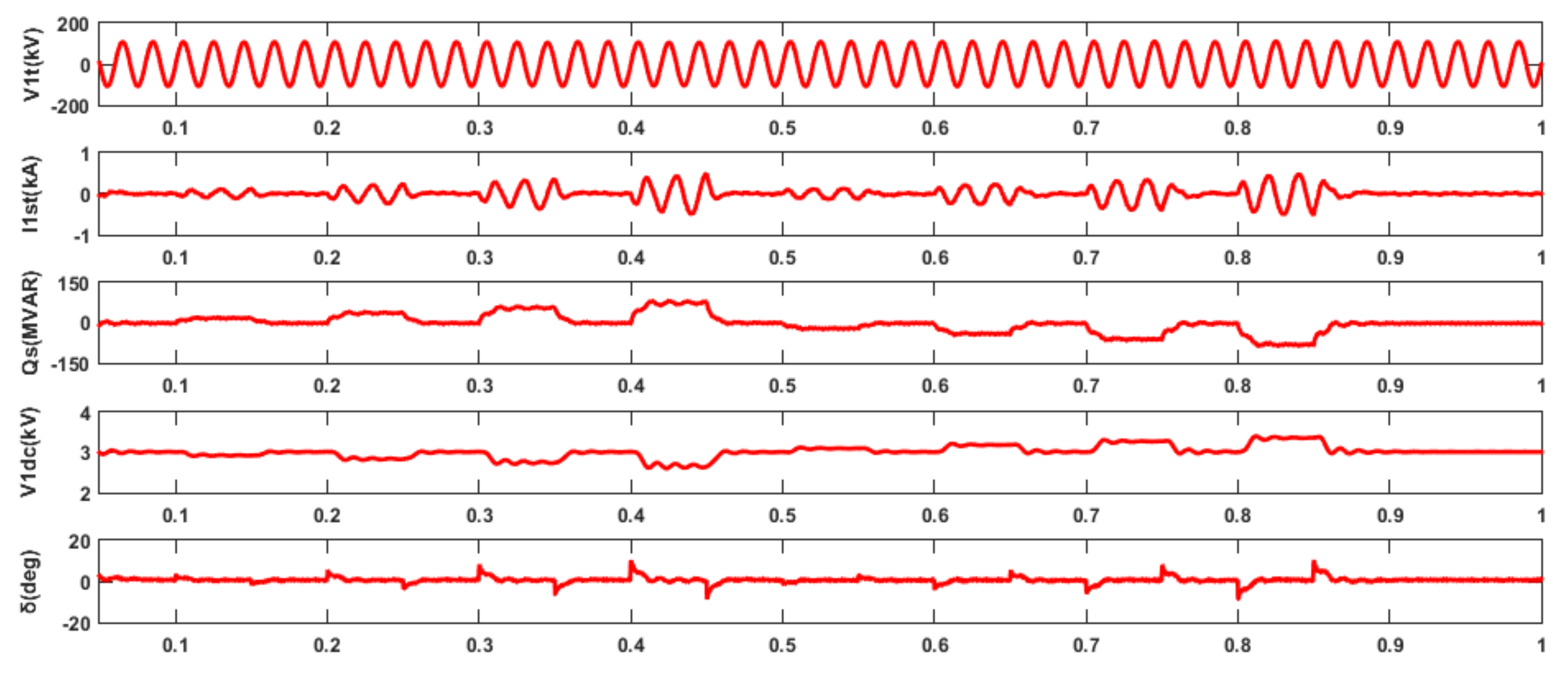
  • i. Dynamic Performance of Reference Reactive Power Changes
The binary weighted transformer integrated seven level VSC based STATCOM was examining with dynamic conditions of inductive and capacitive loads. The various continuous, cumulative and disintegration dynamic state loads were tested.

4.1. Continuous Loads

Figure 3 shows the performance results of the STATCOM at various dynamic conditions of continuous load. Initially, the reactive power variation was set to ‘0’ for 0.2 s and the performance was observed. Then, the reference reactive power is varied from 0 to 100 MVAR and the time interval is between 0.2 s and 0.4 s. The STATCOM performance was observed during this time period and the reactive power flows to the STATCOM side, then the AC output voltage and DC-Link voltage were adopted to the voltage losses. After the reactive power is set to ‘0’ during the time interval 0.4 s to 0.6 s, STATCOM performance results were analyzed during the time interval from 0.4 s to 06 s by presetting the reactive power to ‘0′. The reference reactive power was varied from 0 to −100 MVAR for the time interval between 0.6 s and 0.8 s. The STATCOM performance was observed during this time period and the reactive power flowed from the STATCOM side; then, the AC output voltage and DC-Link voltage are added to the voltage losses. After the reactive power was set to ‘0’ during the time interval 0.8 s to 1.0 s, the STATCOM performance results were given, showing the improvement of the smooth steady-state system with low harmonic distortion.
Figure 4 shows the seven level STATCOM harmonic currents at inductive and capacitive operations of continuous loads. The THD was 3.83%, observed at inductive operation of continuous load, (i.e., the reference reactive power was changed to 100 MVAR). In addition, the THD was 5.10%, observed at the capacitive operation of continuous load, (i.e., the reference reactive power was changed to −100 MVAR).

4.2. Cummulative Loads

Figure 5 shows that the nominal reactive power value starts at 0 and time reaches to 0.1 s. The reference reactive power variation is moved to 35 MVAR within 0.15 s (i.e., 0.1 s to 0.25 s). Again, the cumulative reactive power 40 MVAR is added at 0.25 s, then the actual reactive power ( Q S ) flows in the system without any major overshoots until 0.4 s. Now, the total cumulative inductive load ( Q S * ) is set to 75 MVAR, then the DC-Link voltage starts to decrease. Thus, the AC converter output voltage starts to decrease, then STATCOM will absorb the reactive power ( Q S * ) and, again, maintain the nominal reactive power value of 0 within 0.1 s, (i.e., 0.4 s to 0.5 s). The capacitive load starts at the time 0.5 s in the system with the reference reactive power moved to −35 MVAR and the time reaches 0.65 s. Again, the cumulative reactive power 40 MVAR is added at 0.65 s, then the actual reactive power ( Q S ) flows in the system without any major overshoots until 0.8 s. Now, the total cumulative capacitive load ( Q S * ) is set to −75 MVAR, then the DC-Link voltage will start to increase. Thus, the AC converter output voltage starts to increase, then STATCOM will deliver the reactive power ( Q S * ) and, again, maintain the nominal reactive power value of 0 from 0.8 s to 0.9 s.
Figure 6 shows STATCOM currents’ harmonic spectra during cumulative loads of inductive and capacitive operations. The THD of the STATCOM currents is found to be 3.74% during the inductive operation when ‘ Q S * ’ is set to 75 MVAR, as well as 5.01% during capacitive operation when ‘ Q S * ’ is set to −75 MVAR.

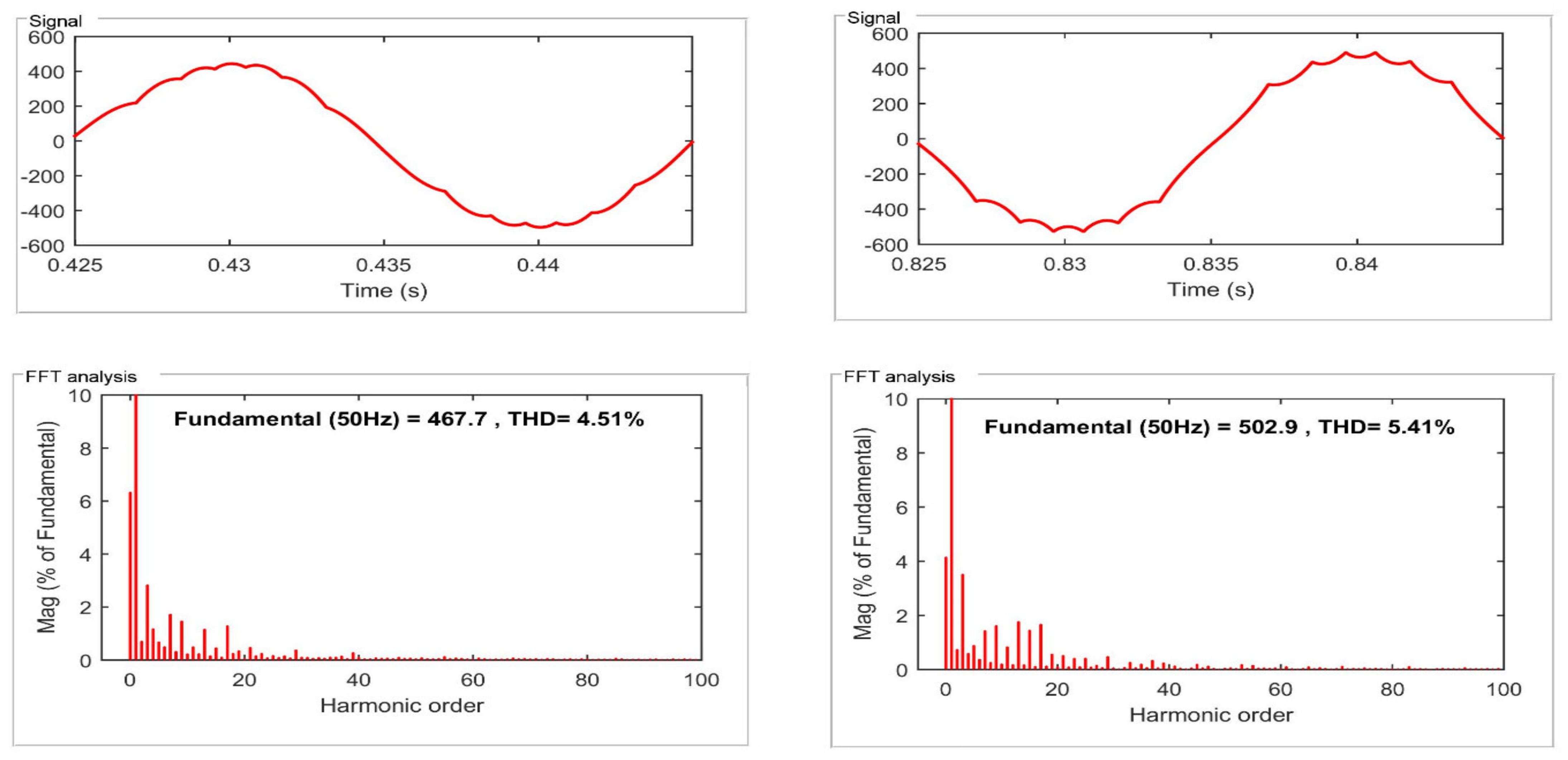
4.3. Disintegration Loads

Figure 7 shows that the starting nominal reactive power value is 0, and time reaches to 0.1 s. From 0.1 s, the variation of reference reactive power is moved to 20 MVAR, and the actual reactive power ( Q S ) flows in the system without any major overshoots until 0.15 s. The DC-Link voltage will start to decrease. Thus, the AC converter output voltage starts to decrease, then STATCOM will absorb the reactive power ( Q S * ) and, again, maintain the nominal reactive power value (i.e., 0) from 0.15 s to 0.2 s. The disintegration inductive load reactive power 40 MVAR is added at 0.20 s, and the actual reactive power ( Q S ) flows in the system without any major overshoots until 0.25 s. Again, STATCOM will absorb the reactive power ( Q S * ), and maintain the nominal reactive power value of 0 from 0.25 s to 0.3 s.
Thus, the disintegration inductive load reactive power 60 MVAR is observed at time 0.30 s, and the actual reactive power ( Q S ) flows in the system without any major overshoots till the time 0.35 s. Then, continuously, STATCOM will absorb the reactive power ( Q S * ) and maintain nominal reactive power value (i.e., 0) from 0.35 s to 0.4 s. Finally, the disintegration inductive load reactive power is moved to 80 MVAR at 0.40 s, and the actual reactive power ( Q S ) flows in the system without any major overshoots until 0.45 s. When Q S * is set to 80 MVAR, the DC-Link voltage will start to decreases. Thus, the AC converter output voltage starts to decrease. Therefore, STATCOM will consume the reactive power, and maintain the nominal reactive power value of 0 from 0.45 s to 0.5 s.
The disintegration capacitive load starts at the time 0.5 s in the system, the reference reactive power is moved to −20 MVAR, and the actual reactive power ( Q S ) flows in the system without any major overshoots until 0.55 s. The DC-Link voltage will start to increase. Thus, the AC converter output voltage starts to increase, then STATCOM will deliver the reactive power ( Q S * ), and, again, maintain the nominal reactive power value of 0 from 0.55 s to 0.6 s. The disintegration capacitive load reactive power −40 MVAR is added at 0.60 s, and the actual reactive power ( Q S ) flows in the system without any major overshoots until 0.65 s. Again, STATCOM will deliver the reactive power ( Q S * ) and again maintain the nominal reactive power value (i.e., ‘0 ‘) from 0.65 s to 0.7 s.
The disintegration capacitive load reactive power −60 MVAR is observed at the time 0.70, s and the actual reactive power ( Q S ) flows in the system without any major overshoots until 0.75 s. Then, continuously, STATCOM will deliver the reactive power ( Q S * ), and, again, maintain the nominal reactive power value (i.e., ‘0’) from 0.75 s to 0.8 s. Finally, the disintegration capacitive load reactive power is moved to −80 MVAR at 0.80 s, and the actual reactive power ( Q S ) flows in the system without any major overshoots until 0.85 s. When ‘ Q S * ’ is set to −80 MVAR, then DC-Link voltage will start to increase. Thus, the AC converter output voltage starts to increase. Therefore, STATCOM will generate the reactive power and, again, maintain the nominal reactive power value of 0 from 0.85 s to 0.9 s.
Figure 8 shows STATCOM currents’ harmonic spectra during disintegration loads of inductive and capacitive operations. The THD of STATCOM currents is found to be 4.51% during the inductive operation when ‘ Q S * ’ is set to 80 MVAR, as well as 5.41% during capacitive operation when ‘ Q S * ’ is set to −80 MVAR.
Table 1 describes the THD percentage of STATCOM currents under inductive and capacitive operations for continuous, cumulative, and disintegration loads of the system at reference reactive power dynamic changes with satisfactory performance results.
Figure 9 shows the performance of seven level VSC based STATCOM at terminal voltage variations at various dynamic conditions. At the starting point, the reference terminal voltage is set to ‘1.0’ pu up to 0.2 s, and then the STATCOM performance is observed. Then, the reference terminal voltage is moved to ‘1.03’ pu during the time interval between 0.2 s and 0.4 s, and the STATCOM performance is verified with waveforms at this stage. STATCOM sends the reactive power; then, the DC-Link voltage and the AC converter output voltage are increased to minimize the system losses. Afterwards, the reference terminal voltage is moved to ‘1.0’ pu during the time interval between 0.4 s and 0.6 s, then the STATCOM performance is observed (similar to the initial stage). Thus, the reference terminal voltage is moved to ‘0.97’ pu during the time interval between 0.6 s and 0.8 s, then the STATCOM performance is verified. STATCOM receives the reactive power, then the DC-Link voltage and the AC converter output voltage are decreased to minimize the system losses. Further, the reference terminal voltage is moved to ‘1.0’ pu during the time interval between 0.8 s and 1.0 s. Then, the overall STATCOM performance is observed with system voltage, system current, load current, converter current, reactive power, DC-Link voltage, per unit terminal voltage, and phase angle waveforms by all the stages from starting to final time periods at various inductive loads and capacitive loads on the system.
Table 2 designates the THD percentage of the system, load, and STATCOM currents under inductive and capacitive operations. The dynamic performance of system, load and STATCOM current conditions at reference terminal voltage changes, with satisfactory results.

5. Statistical Quantative Parameters

The results obtained with the proposed STATCOM operation of a seven level VSC with binary-weighted transformers is compared with the existing approaches shown in Table 3. With low harmonics for 11 kV, a 50 Hz distribution system used a single DC-Link capacitor with eight switches and two transformers. The proposed methodology is applied for a 132 kV, 50 Hz high voltage and high-power transmission system with less harmonic distortion achieved with the minimum number of switches and binary integrated transformers with a unique DC-Link capacitor. With a cascade H-bridge multilevel inverter, less harmonic distortion was achieved by compromising the number of switches to 12 and one extra-low voltage and low-frequency transformer. The harmonic distortion is minimized with a hybrid structure combination of two cells and H-bridges multilevel inverter with flying capacitors for a 400 V, 50 Hz distribution system.

6. Conclusions

A single DC-Link Voltage of seven level VSC based STATCOM has been executed with various continuous, cumulative, and disintegration inductive and capacitive loads. The model has tested by dynamic load variations of nominal system voltage at various currents of inductive and capacitive loads. A combination of binary-weighted transformers and VSC power circuits improves the transmission system voltage levels with unique DC-Link capacitance. The single DC-Link voltage eliminates unbalanced voltage strain on switching devices to maintain smooth voltage waveforms. The firing angles of the switches estimation is based on the levels of VSC based STATCOM for generating the system voltages. The dynamic load performance of the STATCOM has been verified for different instants of continuous inductive and capacitive loads with satisfactory results and low harmonic content. The cumulative load performance was also verified at various inductive and capacitive loads with reasonable results with low harmonic content. The STATCOM also verified the dynamic performance of disintegration inductive and capacitive loads with acceptable results and low harmonic content. STATCOM has been verified with system voltage changes at nominal point value for smooth improving operations, as evidenced by the accurate results. The THD is 12.02%, a lower value than that of conventional VSC configurations. The major advantage of STATCOM is minimizing the number of switches and transformers for voltage enhancement of the high voltage transmission systems.

Author Contributions

L.N.G.: Writing-Original Draft, and Resources; L.N.G. & G.S.R.: Conceptualization, Methodology, Investigation; R.D. & F.P.G.M.: Review & Editing. All authors have read and agreed to the published version of the manuscript.

Funding

The work reported herewith has been financially by the Dirección General de Universidades, Investigación e Innovación of Castilla-La Mancha, under Research Grant ProSeaWind project (Ref.: SBPLY/19/180501/000102).

Institutional Review Board Statement

Not applicable.

Informed Consent Statement

Not applicable.

Data Availability Statement

Not applicable.

Conflicts of Interest

The authors declare no conflict of interest.

Nomenclature

FACTSFlexible AC transmission systems
STATCOMStatic synchronous compensator
VSCVoltage source converter
IGBTsThe insulated gate bipolar transistors
PWMPulse width modulation
FFTFast Fourier transform
MPCMicro processor controller
THDTotal harmonic distortion

Appendix A

System Voltage132 kV
Transformers100 MVA, 50 Hz, Tr 1: 25.4 kV/2.12 kV, Tr 2: 50.8 kV/2.12 kV
DC-Link Voltage3000 V
Capacitor0.07 F
VSC Power Circuits02
No. of GTOs24
GTO’s pulse frequency50 Hz
AC System Voltage Controller GainsKPt = 0.17 and KIt = 0.01
Q-axis current controller gainsKPq = 50 and KIq = 5

References

  1. Abdulveleev, I.; Khramshin, T.; Kornilov, G. Novel Hybrid Cascade H-Bridge Active Power Filter with Star Configuration for Nonlinear Powerful Industrial Loads. In Proceedings of the 2018 International Conference on Industrial Engineering, Applications and Manufacturing (ICIEAM), Moscow, Russia, 15–18 May 2018; pp. 1–7. [Google Scholar] [CrossRef]
  2. Ahmad, Y.; Pinto, S. Cascade multilevel STATCOM as a solution to improve the voltage profile of a power grid. In Proceedings of the 2018 International Young Engineers Forum (YEF-ECE), Costa da Caparica, Portugal, 4 May 2018; pp. 109–114. [Google Scholar] [CrossRef]
  3. Nguyen, T.H.; Al Hosani, K.; El Moursi, M.S.; Blaabjerg, F. An Overview of Modular Multilevel Converters in HVDC Transmission Systems with STATCOM Operation during Pole-to-Pole DC Short Circuits. IEEE Trans. Power Electron. 2018, 34, 4137–4160. [Google Scholar] [CrossRef]
  4. Hao, L.; Hanliang, S.; Liancheng, X.; Anling, L.; Bin, Z. Coordination control of positive and negative sequence voltages of cascaded H-bridge STATCOM operating under imbalanced grid voltage. J. Eng. 2018, 2019, 2743–2747. [Google Scholar] [CrossRef]
  5. Jeon, Y.-T.; Townsend, C.; Tafti, H.D.; Ramos, E.R.; Farivar, G.G.; Park, J.-H.; Pou, J.; Rodriguez, E.R. An Enhanced Static Compensator With DC-Link Voltage Shaping Method. IEEE Trans. Power Electron. 2019, 35, 2488–2500. [Google Scholar] [CrossRef]
  6. Lee, H.; Park, J.-W. An Improved STATCOM based on Hybrid Modular Multilevel Converter. In Proceedings of the 2019 34th International Technical Conference on Circuits/Systems, Computers and Communications (ITC-CSCC), JeJu, Korea, 23–26 June 2019. [Google Scholar] [CrossRef]
  7. Liu, W.; Sun, S.; Liu, Y.; Si, R.; Mao, Y.; Shao, H.; Jia, P. A New Cascaded Multi-Level Phase Structure Suitable for High-Voltage High-Power Applications. In Proceedings of the 2018 2nd IEEE Conference on Energy Internet and Energy System Integration (EI2), Beijing, China, 20–22 October 2018; pp. 1–6. [Google Scholar] [CrossRef]
  8. Chakrabarty, R.; Adda, R. Reduced Switch Single DC Source Cascaded H-bridge Multilevel Inverter based DSTATCOM. In Proceedings of the 45th Annual Conference of the IEEE Industrial Electronics Society, Lisbon, Portugal, 14–17 October 2019; Volume 1, pp. 7074–7079. [Google Scholar] [CrossRef]
  9. Abhilash, T.; Kirubakaran, A.; Somasekhar, V. A Seven-Level Hybrid Inverter with DC-Link and Flying Capacitor Voltage Balancing. In Proceedings of the 2019 IEEE International Conference on Environment and Electrical Engineering and 2019 IEEE Industrial and Commercial Power Systems Europe (EEEIC/I&CPS Europe), Genova, Italy, 11–14 June 2019; pp. 1–5. [Google Scholar] [CrossRef]
  10. Dash, A.R.; Panda, A.K. Experimental validation of a shunt active filter based on cascaded multilevel inverter with single excited DC source. In Proceedings of the 2018 International Conference on Power, Instrumentation, Control and Computing (PICC), Thrissur, India, 18–20 January 2018; pp. 1–6. [Google Scholar] [CrossRef]
  11. Hou, X.; Sun, Y.; Han, H.; Liu, Z.; Su, M.; Wang, B.; Zhang, X. A General Decentralized Control Scheme for Medium-/High-Voltage Cascaded STATCOM. IEEE Trans. Power Syst. 2018, 33, 7296–7300. [Google Scholar] [CrossRef]
  12. Singh, B.; Srinivas, K.V. Three-Level 12-Pulse STATCOM with Constant DC Link Voltage. In Proceedings of the 2009 Annual IEEE India Conference, Ahmedabad, India, 18–20 December 2009; pp. 1–4. [Google Scholar] [CrossRef]
  13. Cajigal-Nunez, J.M.; Winter, P.; Wrede, H. Modern Control Method of MMC STATCOM for Future Power Grids. In Proceedings of the 2019 21st European Conference on Power Electronics and Applications (EPE ‘19 ECCE Europe), Genova, Italy, 3–5 September 2019. [Google Scholar] [CrossRef]
  14. De Oliveira, P.A.; Da Silva, L.E.B.; Gonzatti, R.B.; Pereira, R.R.; Santana, W.C.; Mollica, D. A Practical Guide to Implement Model Based Predictive Control Applied on Cascaded H-Bridge Converters. In Proceedings of the 2019 IEEE 28th International Symposium on Industrial Electronics (ISIE), Vancouver, BC, Canada, 12–14 June 2019; pp. 2027–2032. [Google Scholar] [CrossRef]
  15. Freire, D.F.M.; Caseiro, L.; Mendes, A. Model Predictive Control of a five-level Neutral-Point-Clamped STATCOM. In Proceedings of the 2019 IEEE International Conference on Industrial Technology (ICIT), Melbourne, VIC, Australia, 13–15 February 2019; pp. 1482–1487. [Google Scholar] [CrossRef]
  16. Gidd, A.R.; Gore, A.D.; Jondhale, S.B.; Kadekar, O.V.; Thakre, M.P. Modelling, Analysis and Performance of a DSTATCOM for Voltage Sag Mitigation in Distribution Network. In Proceedings of the 2019 3rd International Conference on Trends in Electronics and Informatics (ICOEI), Tirunelveli, India, 23–25 April 2019. [Google Scholar] [CrossRef]
  17. Jin, Y.; Wang, J.; Liu, Y.; Sai, X.; Ji, Y. Analysis of unbalanced clustered voltage and control strategy of clustered voltage balancing for cascaded H-bridge STATCOM. J. Mod. Power Syst. Clean Energy 2019, 7, 1697–1708. [Google Scholar] [CrossRef] [Green Version]
  18. Murad, M.A.A.; Milano, F. Modeling and Simulation of PI-Controllers Limiters for the Dynamic Analysis of VSC-Based Devices. IEEE Trans. Power Syst. 2019, 34, 3921–3930. [Google Scholar] [CrossRef]
  19. Srinivas, K.V.; Singh, B. Three-Level 24-Pulse STATCOM with Pulse Width Control at Fundamental Frequency Switching. In Proceedings of the 2010 IEEE Industry Applications Society Annual Meeting, Houston, TX, USA, 3–7 October 2010; pp. 1–6. [Google Scholar] [CrossRef]
  20. Li, X.; Xu, Z. Enhanced Efficient EMT-Type Model of the MMCs Based on Arm Equivalence. Appl. Sci. 2020, 10, 8421. [Google Scholar] [CrossRef]
  21. Li, Y.; Humayun, M. Analysis of Cross-Connected Half-Bridges Multilevel Inverter for STATCOM Application. Electronics 2020, 9, 1898. [Google Scholar] [CrossRef]
  22. Zhang, J.; Xu, S.; Din, Z.; Hu, X. Hybrid Multilevel Converters: Topologies, Evolutions and Verifications. Energies 2019, 12, 615. [Google Scholar] [CrossRef] [Green Version]
  23. Chaudhary, S.K.; Cupertino, A.F.; Teodorescu, R.; Svensson, J.R. Benchmarking of Modular Multilevel Converter Topologies for ES-STATCOM Realization. Energies 2020, 13, 3384. [Google Scholar] [CrossRef]
  24. Zubiaga, M.; Sanchez-Ruiz, A.; Olea, E.; Unamuno, E.; Bilbao, A.; Arza, J. Power Capability Boundaries for an Inverter Providing Multiple Grid Support Services. Energies 2020, 13, 4314. [Google Scholar] [CrossRef]
  25. Camargo, R.; Mayor, D.; Miguel, A.; Bueno, E.; Encarnação, L. A Novel Cascaded Multilevel Converter Topology Based on Three-Phase Cells—CHB-SDC. Energies 2020, 13, 4789. [Google Scholar] [CrossRef]
  26. Verdugo, C.; Candela, J.; Rodriguez, P. Quadrature Voltage Compensation in the Isolated Multi-Modular Converter. Energies 2021, 14, 529. [Google Scholar] [CrossRef]
  27. Al Mamun, K.A.; Rahman, H.; Hoque, M.; Islam, N. Design and Simulation of a Reactive Power Compensator Using STATCOM for ‘Muhuri Dam’ Wind Power Plant. In Proceedings of the 2019 International Conference on Energy and Power Engineering (ICEPE), Dhaka, Bangladesh, 14–16 March 2019; pp. 1–5. [Google Scholar] [CrossRef]
  28. Chavan, P.M.; Chavan, G.P. Interfacing of Wind Energy to Grid using Static Compensator and Load Reactive Power Compensation. In Proceedings of the 2018 International Conference on Information, Communication, Engineering and Technology (ICICET), Pune, India, 29–31 August 2018; pp. 1–4. [Google Scholar] [CrossRef]
  29. Elgebaly, A.; Hassan, A.E.-W.; El-Nemr, M.K. Reactive Power Compensation by Multilevel Inverter STATCOM for Railways Power Grid. In Proceedings of the 2019 IEEE Conference of Russian Young Researchers in Electrical and Electronic Engineering (EIConRus), Saint Petersburg and Moscow, Russia, 28–31 January 2019; pp. 2094–2099. [Google Scholar] [CrossRef]
  30. Hasan, S.; Luthander, R.; De Santiago, J. Reactive Power Control for LV Distribution Networks Voltage Management. In Proceedings of the 2018 IEEE PES Innovative Smart Grid Technologies Conference Europe (ISGT-Europe), Sarajevo, Bosnia and Herzegovina, 21–25 October 2018; pp. 1–6. [Google Scholar] [CrossRef]
  31. Neyshabouri, Y.; Chaudhary, S.K.; Teodorescu, R.; Sajadi, R.; Iman-Eini, H. Improving the Reactive Current Compensation Capability of Cascaded H-Bridge Based STATCOM Under Unbalanced Grid Voltage. IEEE J. Emerg. Sel. Top. Power Electron. 2019, 8, 1466–1476. [Google Scholar] [CrossRef]
  32. Orcajo, G.A.; Cano, J.M.; Norniella, J.G.; G., F.P.; Rojas, C.H.; D., J.R.; G., P.A.; R., D.C. Power Quality Improvement in a Hot Rolling Mill Plant Using a Cascaded H-Bridge STATCOM. In Proceedings of the 2019 IEEE Industry Applications Society Annual Meeting, Baltimore, MD, USA, 29 September–3 October 2019; pp. 1–9. [Google Scholar] [CrossRef]
  33. Roy, C.; Chatterjee, D.; Bhattarcharya, T. A Hybrid FACTS Topology for Reactive Power Support in High Voltage Transmission Systems. In Proceedings of the 44th Annual Conference of the IEEE Industrial Electronics Society, Washington, DC, USA, 21–23 October 2018; pp. 65–70. [Google Scholar] [CrossRef]
  34. Carlak, H.F.; Kayar, E. Voltage Regulation Analysis in Energy Transmission Systems Using STATCOM. In Proceedings of the 2019 IEEE East-West Design & Test Symposium (EWDTS), Batumi, Georgia, 13–16 September 2019; pp. 1–7. [Google Scholar] [CrossRef]
  35. Mishra, R.; Agarwal, V. Novel Voltage Balancing Techniques for Modular Multilevel PV Inverters. In Proceedings of the 2018 IEEE Industry Applications Society Annual Meeting (IAS), Portland, OR, USA, 23–27 September 2018; pp. 1–8. [Google Scholar] [CrossRef]
  36. Thakare, S.; Janaki, M.; Thirumalaivasan, R. Improvement in Power Flow Control and Voltage Regulation using UPFC. In Proceedings of the 2019 Innovations in Power and Advanced Computing Technologies (i-PACT), Vellore, India, 22–23 March 2019; Volume 1, pp. 1–4. [Google Scholar] [CrossRef]
  37. Wang, S.; Bao, D.; Gontijo, G.; Chaudhary, S.; Teodorescu, R. Modeling and Mitigation Control of the Submodule-Capacitor Voltage Ripple of a Modular Multilevel Converter under Unbalanced Grid Conditions. Energies 2021, 14, 651. [Google Scholar] [CrossRef]
  38. Di Benedetto, M.; Lidozzi, A.; Solero, L.; Crescimbini, F.; Grbović, P. High-Performance 3-Phase 5-Level E-Type Multilevel–Multicell Converters for Microgrids. Energies 2021, 14, 843. [Google Scholar] [CrossRef]
  39. Brando, G.; Chatzinikolaou, E.; Rogers, D.; Spina, I. Electrochemical Cell Loss Minimization in Modular Multilevel Converters Based on Half-Bridge Modules. Energies 2021, 14, 1359. [Google Scholar] [CrossRef]
  40. Kim, U.-J.; Oh, S.-G. New Sub-Module with Reverse Blocking IGBT for DC Fault Ride-Through in MMC-HVDC System. Energies 2021, 14, 1551. [Google Scholar] [CrossRef]
  41. Damian, I.-C.; Eremia, M.; Toma, L. Fault Simulations in a Multiterminal High Voltage DC Network with Modular Multilevel Converters Using Full-Bridge Submodules. Energies 2021, 14, 1653. [Google Scholar] [CrossRef]
  42. Jeong, I.; Sung, T. One-Cycle Control of Three-Phase Five-Level Diode-Clamped STATCOM. Energies 2021, 14, 1830. [Google Scholar] [CrossRef]
  43. Ayala-Chauvin, M.; Kavrakov, B.; Buele, J.; Varela-Aldás, J. Static Reactive Power Compensator Design, Based on Three-Phase Voltage Converter. Energies 2021, 14, 2198. [Google Scholar] [CrossRef]
  44. Afzal, M.; Khan, M.; Hassan, M.; Wadood, A.; Uddin, W.; Hussain, S.; Rhee, S. A Comparative Study of Supercapacitor-Based STATCOM in a Grid-Connected Photovoltaic System for Regulating Power Quality Issues. Sustainability 2020, 12, 6781. [Google Scholar] [CrossRef]
Figure 1. (a) STATCOM configuration with seven level VSC. (b) seven level voltage source converter voltage output waveforms. (c) Harmonic spectrum of seven level voltage source converter voltage output waveforms.
Applsci 11 07330 g001aApplsci 11 07330 g001b
Figure 2. Control strategy for the proposed STATCOM.
Applsci 11 07330 g002
Figure 3. Continuous load performance results of seven level VSC based STATCOM with reference reactive power changes.
Applsci 11 07330 g003
Figure 4. STATCOM currents harmonic spectra during continuous loads of inductive and capacitive operations.
Applsci 11 07330 g004
Figure 5. Cumulative load performance results of seven level VSC based STATCOM with reference reactive power changes.
Applsci 11 07330 g005
Figure 6. STATCOM currents’ harmonic spectra during cumulative loads of inductive and capacitive operations.
Applsci 11 07330 g006
Figure 7. Disintegration loads performance results of seven level VSC based STATCOM with reference reactive power changes.
Applsci 11 07330 g007
Figure 8. STATCOM currents harmonic spectra during disintegration loads of inductive and capacitive operations.
Applsci 11 07330 g008
Figure 9. Performance of seven level VSC based STATCOM at terminal voltage variations.
Applsci 11 07330 g009
Table 1. STATCOM current THD at various loads.
STATCOM Current OperationLoads%Total Harmonic Distortion (THD)
Under inductive
Under capacitive
Continuous3.83
5.10
Under inductive
Under capacitive
Cummulative3.74
5.01
Under inductive
Under capacitive
Disintegration4.51
5.41
Table 2. THD at various currents.
CurrentOperation% Total Harmonic Distortion (THD)
SystemUnder inductive
Under capacitive
1.89
2.88
LoadUnder inductive
Under capacitive
0.90
1.43
STATCOMUnder inductive
Under capacitive
2.80
4.26
Table 3. Comparative study for existing methods.
Ref Papers/
Components
SwitchesTransformersCapacitorsDC SourceSystem Voltage
[10]12311100 V
[9]8-3-400 V
[8]821-11 kV
Proposed821-132 kV
Publisher’s Note: MDPI stays neutral with regard to jurisdictional claims in published maps and institutional affiliations.

