Article

Instant Center Identification of Single-Loop Multi-DOF Planar Linkage Using Virtual Link

1
School of Mechanical Engineering and Electronic Information, China University of Geosciences, No. 388 LuMo Road, Hongshan District, Wuhan 430074, China
2
Center for Manufacturing Research, Tennessee Technological University, Cookeville, TN 38505, USA
3
Faculty of Engineering Sciences Institute of Mechatronics and System Dynamics, University of Duisburg-Essen, 47057 Duisburg, Germany
*
Author to whom correspondence should be addressed.
Appl. Sci. 2021, 11(10), 4463; https://doi.org/10.3390/app11104463
Submission received: 30 March 2021 / Revised: 12 May 2021 / Accepted: 12 May 2021 / Published: 14 May 2021
(This article belongs to the Special Issue Innovative Robot Designs and Approaches)

Abstract

:
Instant center is an important kinematic characteristic which can be used for velocity and singularity analysis, configuration synthesis and dynamics modeling of multi-degree of freedom (multi-DOF) planar linkage. The Aronhold–Kennedy theorem is famous for locating instant centers of four-bar planar linkage, but for single-loop multi-DOF linkages, it fails. Increasing with the number of the links of single-loop multi-DOF planar linkages, the lack of link relationship makes the identification of instant center become a recognized difficulty. This paper proposes a virtual link method to identify instant centers of single-loop multi-DOF planar linkage. First, three types of instant centers are redefined and the instant center identification process graph is introduced. Then, based on coupled loop chain characteristic and definition of instant center, two criteria are presented to convert single-loop multi-DOF planar linkage into a two-loop virtual linkage by adding the virtual links. Subsequently, the unchanged instant centers are identified in the virtual linkage and used to acquire all the instant centers of original single-loop multi-DOF planar linkage. As a result, the instant centers of single-loop five-bar, six-bar planar linkage with several prismatic joints are systematically researched for the first time. Finally, the validity of the proposed method is demonstrated using loop equations. It is a graphical and straightforward method and the application is wide up to single-loop multi-DOF N-bar (N ≥ 5) planar linkage.

1. Introduction

The concept of instant center is proposed by Bernoulli [1], which refers to the zero velocity point for two rigid bodies in a planar motion. It is not only used to analyze kinematics of linkages such as absolute velocity and angular velocity, but also to research singular configurations [2,3,4,5], configuration synthesis [6] and dynamics modeling [7]. Generally, instant centers are obtained by Aronhold–Kennedy theorem [8], but if the linkages contain more links or link loops, the traditional method fails. The instant center which cannot be directly located by Aronhold–Kennedy theorem, is called “indeterminate instant center” [9] or indeterminate secondary instant center in Refs. [10,11,12,13,14,15,16,17,18,19,20,21,22,23,24]. Moreover, it exists in almost all linkages besides single-loop four-bar linkage and Stephenson linkage. Therefore, the location of indeterminate secondary instant center is a difficulty of kinematics analysis of planar linkages, which attracts many researchers’ interests. Dijksman [10] proposed a graphical linkage reduction method to find coordinated centers of curvature by changing the pentagonal loop into four-bar loop. The disadvantage of this method is that the joint-joining operation may have to be carried out twice and each time in a different way. Based on singular coefficient matrix of the derived velocity equations, Yan and Hsu [11] presented an analytical method to locate instant centers of single or multiple degrees of freedom linkages. This method has tedious calculation. Klein [12] raised a graphic method of trial-and-error type to identify the right position of the center. The defect is that the process is complex and inefficient. Forster and Pennock [9,14,15,16] presented both analytical method and graphical technique to solve instant center problem of single-DOF, two-DOF planar indeterminate linkage and three-DOF planar six-bar linkage. The essence of this method is first to determine one indeterminate secondary instant center by combing two arbitrary possible positions, then to reverse all the indeterminate instant centers, but its implementation method is roundabout. Based on instant centers of the cam pair residing on the extension line of a primary adjacent link, Chang [17,18,19] introduced a virtual cam method to help locate key instant centers of the linkages up to ten-bar. This method is a graphical one and is accurate in AutoCAD, but the applicable rate is not high. In addition, in some cases, it needs to work with Pennock’s method [9,14,15,16], then the linkages can be solved. Di Gregorio [20] presented an algorithm to calculate the positions of indeterminate secondary instant centers of the indeterminate linkages. Although the analytical method uses only pieces of information of the linkage configuration, the difficulty is how to write the equations together with the closure equations of the mechanism to allow the computation of the instant centers’ positions as a function of the generalized coordinate chosen to identify the mechanism configuration. Obviously, it is not easy. Kung and Wang [21] proposed the concept of instant center walk and instant center circuit and established the recursive formula to compute the coordinates of the instant centers. However, the drawback is that the application is only for single-DOF indeterminate linkages at non-singular configurations. According to the fact that an indeterminate secondary instant pole of two-DOF spherical linkage lies somewhere on the unique great circle for a specific configuration of the linkage, Zarkandi [22] provided two techniques to convert a single-DOF spherical mechanism to a two-DOF one, and then locate all the indeterminate secondary instant centers. The main issue is how to use the techniques, and it is not universal for different linkages. Valderrama-Rodríguez [23,24] presented a screw theory approach for the computation of instant rotation axes of the spherical linkages requiring the solution and comparison of two quadratic equations. Although this method is simpler than the previous literature, the calculation is relatively complex. Diab [25] utilized the location of the instant centers to perform acceleration analysis of a four-bar mechanism. On the basis of an adequate literature analysis, Sancibrian and Sarabia [6] presented a synthesis method based on optimization in which the identification of instant center is included in the objective function for rigid-body guidance synthesis Moreover, this proved approach is robust, accurate and efficient. Depended on the fact that the positions of instant centers can determine the velocity coefficients and the virtual work of the external forces of the mechanism, Di Gregorio [7] provided a dynamic model and an algorithm to solve the dynamic problems of single-DOF planar linkage. It is simple to use and numerically effective. In addition, since the relationships between the positions of the instant centers and the absolute velocities, instant centers are possibly used in some other applications such as dynamic model of the spherical mechanisms [26,27], wrench capability analysis of the redundant mechanisms [28], dynamic balancing analysis [29], and even commercial packages. For dynamic model of the spherical parallel mechanism, based on the principle of virtual work, the dynamic model can be built with the Jacobian matrices including angular velocities. As we all know, in a certain mechanism, once the instant centers are located, the corresponding angular velocities are decided. That is, the instant centers are able to address the dynamic model. For wrench capability analysis of the redundant planar parallel manipulator, joint torques, which are decided by the forces and moments acting on the end-effector, are the kinematic condition to sustain the wrench. They can be deduced by the derivatives of absolute velocities obtained from the instant centers. For dynamic balancing analysis of a given mechanism [29], the positions of instant centers can directly be used to calculate the angular momentum which effects whether the sum of all forces and moments acting on the based are zero. For commercial packages, the identification of instant centers may be available as a plug-in of the AutoCAD tool since the instant centers have a widespread application and the proposed method is suited to be programmed. As for real devices where imperfections are unavoidable in production processes, another application of instant center is found inspired by Profs. Bucolo and Buscarino‘s paper [30]. In their research, the nonlinear dynamical circuits are built to help investigate the performance of a novel control strategy for imperfect systems, and the instant center may be used to calculate the dynamical equations which regulate the behavior of the circuits. Although instant center, which is a basic kinematic property, is a useful tool to analyze kinematics of the linkages [2,3,4,5,31], rigid-body synthesis [6], dynamics modeling [7], and dynamic balancing analysis [29] of planar linkages, and it can be used in spatial mechanisms [26,27], redundant mechanisms [28], imperfect systems of real devices [30], and is even available in commercial packages, the identification of instant center is difficult since the lack of relationship of the interval links in a N-bar loop (N ≥ 5). As discussed above, the existing methods can be classified three types: (1) graphical method [10,12,17,18,19,22], (2) analytical method [11,20,23,24], and (3) both analytical method and graphical method [9,14,15,16]. The graphical method has the advantage of visualization, but the defects are complex process and low applicable rate. The analytical method has the merit of high accuracy, but the calculation is normally complicated. Both analytical method and graphical method has both advantages, but the implementation method is roundabout. The generality and simplicity of instant center identification method is still a challenge.
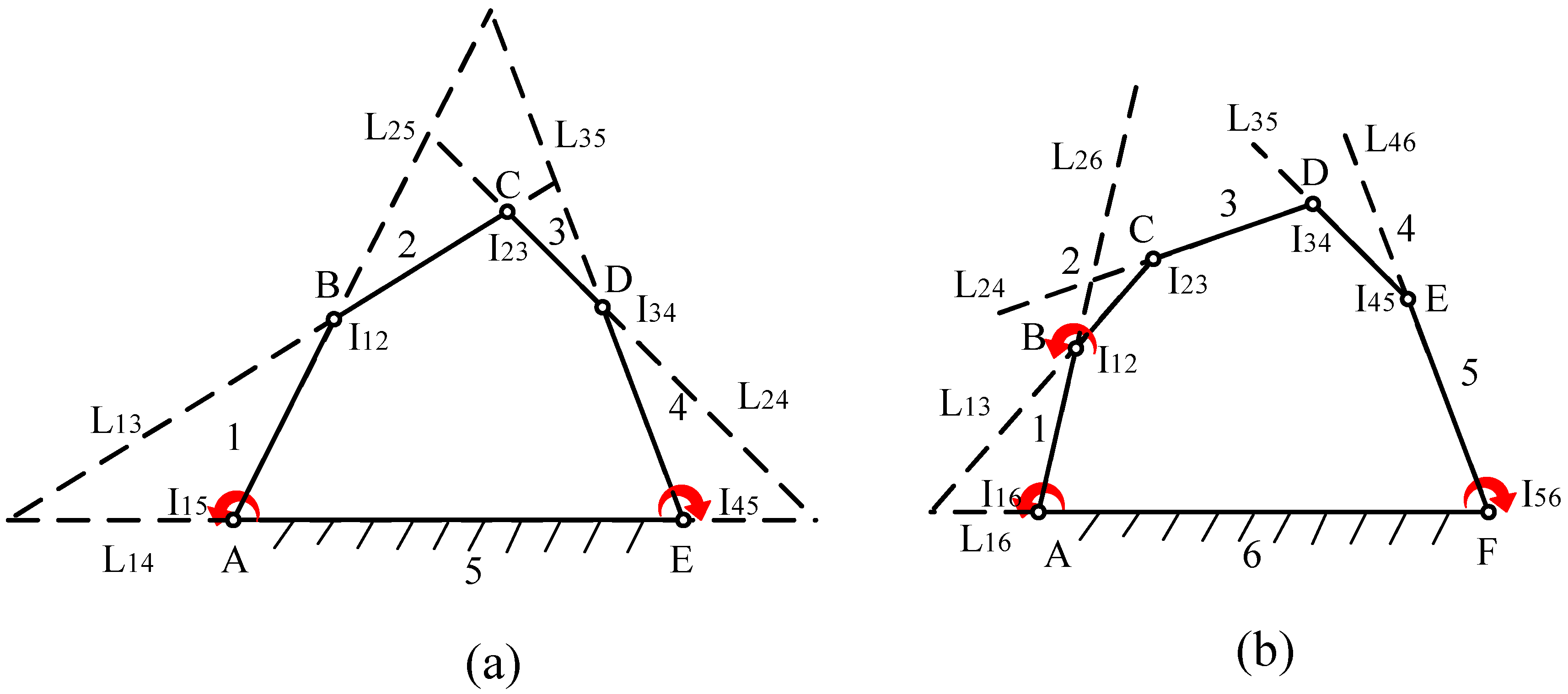
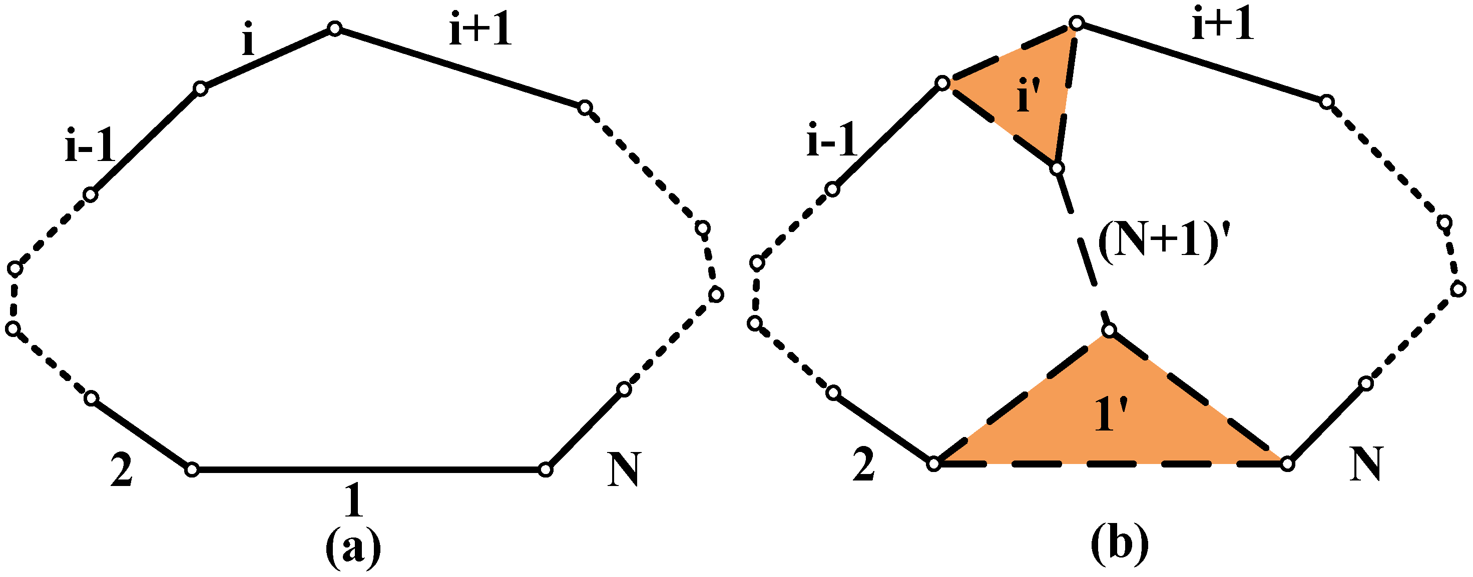
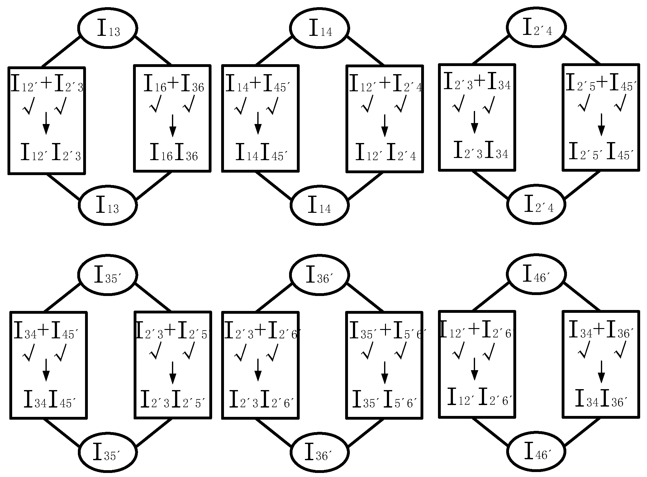
The motivation of this paper is to propose a universal method to identify instant centers of planar linkages, especially for single-loop multi-DOF planar linkages. Based on coupled loop chain characteristic and definition of instant center, a single-loop multi-DOF planar linkage is changed into the two-loop linkage with the added virtual links using the proposed criteria, and the unchanged instant centers are identified according to Aronhold–Kennedy theorem, then all the instant centers of the original single-loop multi-DOF planar linkage can be obtained by the instant center identification process graph. The essence of the proposed method is to cover the shortage of the lacking link relationships of the single-loop linkage using virtual link operation, then obtain the indeterminate instant centers. The virtual link operation is an auxiliary mean which does not affect the motion of the original single-loop linkage. Moreover, the instant center identification of the single-loop multi-DOF planar linkage can be the basic of the instant center identification for multi-loop multi-DOF planar linkage which is discussed in our further research. That is, the proposed method may solve the instant center problem of the planar linkages no matter how many number of the links the linkages contain.
The first contribution of this paper is to provide a virtual link method to identify instant centers of the single-loop multi-DOF planar linkage, which is a graphical method and sticks to the definition of instant center. Compared to the previous literature [10,11,12,13,14,15,16,17,18,19,20,21,22], the proposed method has three advantages: simplification, concision, and validity. Firstly, to build virtual link operation, a few steps are carried out and normally, only one virtual link added operation is required. There is no need to choose the specific link and to perform repetitive complex steps [9,10,12,14,15,16]. Secondly, the location operation is completely decided by the drawing graph, which also can be programmed and automated in AutoCAD. The closure equations are unnecessary [11,20]. Thirdly, the proposed method is only based on instantaneous configuration of the linkage and the definition of instant center, and to ensure universality, the parameters of the virtual links are arbitrary. As a result, the application of this method is universal no matter what the degrees of freedom and the components of the joints of the linkage are [17,18,
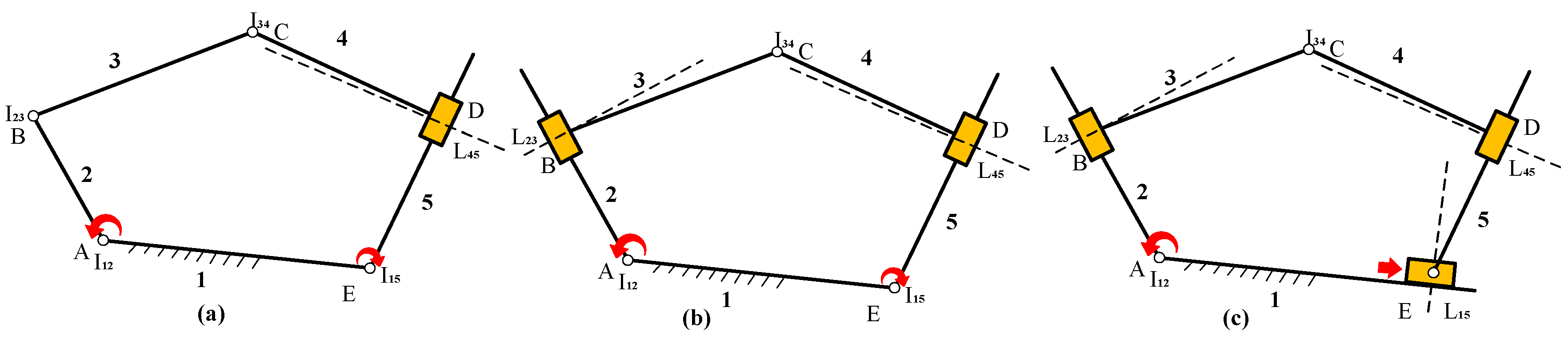
19]. The second contribution is to redefine three types of instant centers. The new classification is more accurate and detailed compared to the existing classification, which brings convenience for further research about instant centers. The third contribution is that the instant center problem of the single-loop five-bar, six-bar planar linkages with only rotation joints and several prismatic joints is solved. Note that the instant centers of single-loop five-bar, six-bar planar linkages with several prismatic joints are the first time to be located, to our best knowledge. The proposed method provides a geometry loop insight to reveal the relationship between the formation of the instant center and the motion of the mechanism, and a new research idea for the study of instant centers.
This paper is organized as follows. In Section 2, the mathematics definition is presented and three types of instant centers are redefined. In Section 3, based on coupled loop chain characteristic and definition of instant center, two criteria to determine instant centers are provided, and the instant center identification process graph is introduced. Instant centers of the Stephenson six-bar linkage are identified to explain how the proposed method works. Then, the steps of instant center identification of single-loop multi-DOF N-bar (N ≥ 5) planar linkages are summarized. Subsequently, the mathematical proof is shown in Section 4. Finally, in Section 5, instant centers of the single-loop five-bar and six-bar planar linkages with only rotation joints and several prismatic joints are located using the criteria, and conclusions are presented at the end of this paper.

2. Mathematic Definition and Classification of Instant Center

Instant center is defined as a point where the relative velocity of the two rigid bodies is zero in a planar motion, but the absolute velocity may be not. For a given planar linkages, the positions of instant centers are varying yielding to the input condition when the planar linkage continuously moves. In fact, the continuous motion of the linkage is formed by lots of instantaneous configurations. Each instantaneous configuration corresponds to one specified input at this instant. That is, an instantaneous configuration coming from the continuous motion linkage is a momentary configuration in which the corresponding momentary input is specified. Moreover, different instantaneous configurations correspond to different specified ratios of the inputs. If the same linkage moves from one instantaneous configuration to the other instantaneous configuration, the specified ratios of the inputs should be accordingly changed. In this paper, instant centers of the instantaneous configuration are discussed, i.e., the linkages researched in our paper are all discussed on the condition that the linkages are all the instantaneous configurations, only one specified ratio of the inputs corresponds to the corresponding instantaneous configuration. Since the momentary input condition is specified in the instantaneous configuration, the passive angles of the linkage can be decided at this instant. In another word, the link relationships (i.e., instant centers) of the instantaneous configuration can be all obtained at the exact points at this instant based on mathematic definition above. In Figure 1, the location of the instant center I13 can be expressed as followed.
V13 = W1 × r1 = W3 × r3
where V13 is absolute velocity of the links 1 and 3, and Wi and ri (i = 1 or 3) denote the angular velocity of corresponding link and distance between the binary link from the point, respectively. Equation (1) represents the fact that the absolute velocity V13 of the instant center I13 only relatives to the angular velocity Wi and the corresponding distance ri in a instantaneous configuration where the momentary input condition is specified and the link parameters of the planar linkage are determinate. It means that the identification of instant center in the instantaneous configuration is only related to the positions and motions (i.e., distances and angular velocities discussed in above) of the participant links (links 1 and 3 in Figure 1) and is irrelevant to the other link of the instantaneous configuration. In another word, when the positions and motions of participant links are the same regardless of whether the remaining links of the linkage changed or not, the corresponding instant center is the same. This property, evolved from the definition, is the theoretical basis to research the single-loop multi-DOF planar linkage in the following sections of this paper. In addition, it is used and proved in Ref. [32] for invariant link rotatability of N-bar kinematic chains. It is worth noting that the property above is effective in instantaneous configurations, but it fails when the linkage is in a continuous motion. The reason is that the passive angular velocity of the participant links (for example links 1 and 3 in Figure 1) is timely drove by the input link (link 4) and the limits coming from sizes of the links. Although the distances and the angular velocities of other links of the moving planar linkage do not occur in Equation (1), they still influence the positions and motions of the participant links. All the locations of the instant centers are continuously varying. However, for instantaneous configurations, each instantaneous configuration corresponds to one specified input at this instant. The ratio of the inputs of an instantaneous configuration is specified, the momentary input is known and invariable.
In literatures above [9,10,11,12,13,14,15,16,17,18,19,20,21,22,23,24], instant centers are classified into two types: primary instant center and secondary instant center. For a given linkage, primary instant center is constantly the coincident point for a pair of rigid bodies of a planar linkage. The other instant centers are all secondary instant centers no matter whether they can be located with Aronhold–Kennedy theorem. However, in this paper, instant centers are classified into three types in view of the access: first instant center, secondary instant center and third instant center. First instant center is same to primary instant center of the existing literatures. It is the easiest to be obtained and is also the base to locate the secondary and third instant centers, such as I12, I23, I14, and I34 in Figure 1. The instant centers, which can be directly received according to the established first instant centers using Aronhold–Kennedy theorem, are called as secondary instant center. It is different to the concept of secondary instant center of the existing literatures. In the new classification, all the secondary instant centers can be located with Aronhold–Kennedy theorem. They have exact positions. For Figure 1, the secondary instant centers are I13, I24. Apart from first and secondary instant centers, the remaining instant centers of the linkages are third instant center. Since its indeterminacy, the identification of third instant center is a difficulty for single-loop multi-DOF planar linkages. Compared to secondary instant center, third instant center can also be determined by Aronhold–Kennedy theorem, but the difference is that secondary instant center can be acquired straightforwardly using the existing first instant centers but third instant center is not. The third instant center I13, formed by the link 1 and link 3 in Figure 2a, is this case. The instant center I13 is a point lying on the extension line of link 5, but the exact location is unknown. That is, the location of third instant center needs other addition information. According to whether third instant center exists on a known line (at least two instant centers on the line are known, normally, the extension line of the link), two types third instant center can be concluded. When a third instant center lies on a known line, the third instant center is an A type third instant center. If not, it is a B type. Taking third instant centers in Figure 2a for example, the instant center I13, I14, I24, I25, and I35 (also represented as L13, L14, L24, L25, and L35, L means that the instant centers are on the lines, but their exact locations are unknown) are all the A type third instant centers. Obviously, there is no B type third instant center. For Figure 2b, the instant center I14, I25 and I36 are all the B type third instant centers. What is noteworthy is that the shortest topological distance of the two links coming from the instant center can be used to distinguish which type the third instant center belongs to. The discrimination process is shown as follows. If the shortest topological distance is less than two units, which means that there is only one link among the two links, the corresponding instant center is an A type third instant center. For Figure 2a, the link 2 is the only link for the A type instant center I13 formed by the links 1 and 3. The B type third instant center I14 has two links (i.e., links 2 and 3) between the formed links 1 and 4 in Figure 2b. Compared to the listed literatures, the new classification is more detailed and accurate.

3. Virtual Link Method for Instant Center Identification

3.1. Criteria for Instant Center Identification

In order to explain the formation of the two proposed criteria, the instant center identification of the Stephenson linkage containing two-loop, in Figure 3, is taken as an example as follows.
The Stephenson linkage has C62 = 15 instant centers (Figure 3). The seven instant centers I12, I23, I34, I14, I35, I56, and I16 are the first instant centers, and the secondary instant centers are the centers I13, and I24. The rest of the instant centers, such as I15, I36, I46, I25, I26, and I45, are the A type third instant centers shown in Table 1. Since no B type third instant center exists, instant centers of the Stephenson linkage are easy to be located with Aronhold–Kennedy theorem. In order to efficiently use the existing first or secondary instant centers to locate the third instant centers, the instant center identification process graph is introduced, which makes the location operation visible and efficient. The essence of the instant center identification process graph is the visualization of third instant center identification using Aronhold–Kennedy theorem. For example, the third instant center identification process graph of Stephenson linkage is shown in Figure 4. The instant center identification process graph is built by the third instant centers and the lines formed by other instant centers except for themself. The symbols “√”, “×”, solid “↓” and hollow “↓” of the graph denote determinate instant center, indeterminate instant center, determinate line and indeterminate line, respectively. The steps of the identification process are shown as follows. Firstly, the third instant centers are all listed on the top. Secondly, using Aronhold–Kennedy theorem, the third instant center can be divided into four instant centers on two possible Aronhold–Kennedy lines. As for instant center I15, the four centers are the instant centers I16, I56, I13, and I35. Thirdly, if the four instant centers are all determinate instant centers, i.e., four √, then the two lines can be decided (i.e., two solid ↓). For instant center I15, the two lines are line I16I56 and line I13I35. Finally, the third instant center can be identified in which the two determinate lines cross. For Figure 4, all the instant centers of the Stephenson linkage can be directly obtained with Aronhold–Kennedy theorem, but for single-loop multi-DOF N-bar (N ≥ 5) planar linkage with B type third instant centers, the situation becomes complex. In this paper, the concept of coupled loop chain characteristic and virtual link operation are proposed to solve the instant center identification of single-loop multi-DOF N-bar (N ≥ 5) planar linkage.

3.1.1. Coupled Loop Chain Characteristic

In the view of loop chain, the instant centers of the Stephenson linkage (Figure 3) can be located as follows. Firstly, three loop chains are found: loop 1-2-3-4, loop 1-4-3-5-6, and loop 1-2-3-5-6. The coupled loop chain 3-5-6-1 is the common part of two loops if the loop 1-4-3-5-6 and loop 1-2-3-5-6 are grouped. For the loop 1-2-3-5-6, there exists one instant center I131. However, for the other loop 1-4-3-5-6, the other instant center I132 can also be obtained. Only when the instant centers I131 and I132 come cross, can the Stephenson linkage be formed. In other words, only if the common instant centers I131 and I132 of two loops coincide, the Stephenson linkage exists. In the loop 1-2-3-5-6 and loop 1-4-3-5-6, the instant centers I131 and I132 are all A type third instant centers, which lie on the extension lines of link 2 and link 4, respectively. That is, the instant center I13 occurs at the point of the intersection of the two line when the instant center I131 and I132 coincide. Similarly, if combining the two loops: loop 1-2-3-4 and loop 1-4-3-5-6, the same result can be obtained. This property, here called coupled loop chain characteristic, is discussed and demonstrated in Refs. [11,12,13,14,18].

3.1.2. Virtual Link Operation

According to discussion above, for single-loop multi-DOF N-bar (N ≥ 5) planar linkage, two criteria and corresponding virtual link operation are presented to locate instant centers as follows.
Criterion 1: For a single-loop multi-DOF N-bar (N ≥ 5) planar linkage, add the virtual links without changing instantaneous configuration to take shape the two-loop virtual linkage in which the instant centers are easy to be determined. Based on mathematics definition of instant center, some of the obtained instant centers in virtual linkage are equivalent to the ones in the original linkage.
Criterion 2: Based on coupled loop chain characteristic, in a certain linkage, if several common instant centers exist when combining any two loops of the linkage, once any pair of common instant centers obtained from different loop chain come cross, the rest common instant centers must coincide, accordingly.
Note that, virtual link operation is an assumption, and the virtual links are unreal. Virtual link operation is an auxiliary means to change the single-loop linkage into a virtual two-loop linkage which do not affect the motion of the original single-loop linkage. That is, the virtual two-loop linkage is actually still the single-loop linkage. The inputs and the motions of the links (not including the virtual links) in the virtual two-loop linkage are the same compared to the original single-loop linkage. The corresponding mathematical proof is discussed in detail in Section 4.

3.2. Process for Instant Center Identification

For single-loop multi-DOF N-bar (N ≥ 5) planar linkage, as shown in Figure 5a, there are CN2 instant centers including no secondary instant center. According to two criteria above, the single-loop multi-DOF N-bar (N ≥ 5) planar linkage can be transformed into the two-loop virtual planar linkage which is combined by a N-bar virtual loop and a (N − 1)-bar virtual loop when N is odd number or two (N − 1)-bar virtual loops when N is even number by adding the middle virtual links N + 1’ in Figure 5b (the number m of the middle virtual links depends on what odd number or even number N (N ≥ 5) belongs to. For example, 5 is the first odd number for N, the number m is one for single-loop five-bar planar linkage. 7 is the second odd number for N, therefore, for seven-bar linkage, the number m is two. The number m is three in nine-bar linkage. Similarly, 6 is the first even number for N, so the number m is one for single-loop six-bar linkage, and the number m is two for eight-bar linkage. It is three in 10-bar linkage. The rule of adding virtual links is to ensure that the number of the two formed virtual loops are same or the difference is 1). If the common instant centers of the two formed virtual loops are located, all the instant centers of the two-loop virtual planar linkage can be identified, and then the instant center problem of the original N-bar planar linkage can be solved with Aronhold–Kennedy theorem. Six steps are summarized for the instant center identification of single-loop multi-DOF N-bar (N ≥ 5) planar linkage as follows. The corresponding flow chart is shown in Figure 6.
Step 1: Calculate the number of instant centers and classify the instant centers according to the proposed classification, then form the instant center Table.
Step 2: Form the instant center identification process graph and choose the right links to build the common instant centers. The common instant centers can be formed by the unchanged links after virtual link operation or directly come from the virtual links. The common instant centers and virtual link operation are interdependent. In another word, the rule of adding virtual links discussed above is the rule to choose the common instant centers, to some extent.
Step 3: Check if the number N (N ≥ 5) belongs to odd number or not.
Step 4: Based on the results from Steps 2 and 3, add the corresponding virtual links to form two-loop virtual planar linkage.
Step 5: Use Criterions 1 and 2 to locate the common instant centers of the two-loop virtual planar linkage. If not, back to Step 3 to add new virtual links in the existing virtual loop until the common instant centers can be obtained. Step 3-Step 4-Step 5 is a iteration loop. The proposed method is suitable to be programmed.
Step 6: Determinate the remaining instant centers of the original N-bar planar linkage which fails to be located in Step 5 using Aronhold–Kennedy theorem.

4. Mathematical Proof

Loop equation is a common mathematical tool to analyze the kinematics of planar linkages. It is employed here to verify the validity of virtual link operation in the instantaneous configuration. Taking the single-loop five-bar planar linkage (red part in Figure 7a, i.e., loop1-2-3-4-5), for example, the known variables are the input angles θ2, θ5 and the link parameters a1, a2, a3, a4, and a5, i.e., the passive angles θ3, and θ4 are unknown. Choosing the angle θ4 as the output, the loop equation of the single-loop five-bar planar linkage can be expressed as
Mathematical proof for single-loop five-bar planar linkage.
Loop ABCDE:
a 1 + a 2 e i θ 2 + a 3 e i θ 3 a 4 e i θ 4 a 5 e i θ 5 = 0
Using Euler formula, Equation (2) can be written as the following two equations:
a 1 + a 2 cos θ 2 + a 3 cos θ 3 a 4 cos θ 4 a 5 cos θ 5 = 0
a 2 sin θ 2 + a 3 sin θ 3 a 4 sin θ 4 a 5 sin θ 5 = 0
Eliminating the unknown angle θ3 in Equations (3) and (4) according to the trigonometric function ( sin θ 3 ) 2 + ( cos θ 3 ) 2 = 1 ,
θ4 = M12, θ5)
Differentiating Equation (5) with respect to time, yields,
W 4 = θ 4 = M 2 ( θ 2 , θ 5 )
where Mi (i = 1, 2) are the coefficients in the light of θ2 and θ5, which can be obtained with mathematical software Maple. Note that Mi is constant. Equation (6) shows that the angular velocity W4 of the single-loop five-bar planar linkage is only related to the input angle θ2, θ5.
After adding the virtual links, the single-loop five-bar linkage (Figure 7a) is changed into a virtual Stephenson linkage (Figure 7b). According to discussion above, the sizes and positions of the virtual links 1’, 3’, and 6’ are arbitrary, hence, there are no known parameters added. Note that the links 1 and 3 (Figure 7a) and the links 1’and 3’ in Figure 7b are different. Seeing from Figure 7a, the link 3 has only one angular velocity, the derivative of angle θ3 in loop ABCDE. However, the link 3’ (Figure 7b) has three angular velocities: the derivative of angle θ3 in loop ABCDE, the derivative of angle θ31 in loop GFCDE, the derivative of angle (θ31 + 2π – β − η) in loop ABFG. As for the links 1 and 1’, the similar result can be concluded. Therefore, the instant center I1’3’ in the virtual Stephenson linkage is not same to the instant center I13 in the single-loop five-bar planar linkage. In fact, the virtual link operation is an assumption. The virtual links are unreal. The virtual Stephenson linkage is actually still the single-loop five-bar linkage. The inputs and the motions of the links (not including the virtual links) in the virtual Stephenson linkage are the same compared to the original single-loop five-bar linkage. The instant centers which are formed by the virtual links 1’, 3’, and 6’, such as I1’2, I1’3’, I1’4, I1’5, I1’6’, I23’, I26’, I3’4, I3’5, I3’6’, I46’, and I56’ in Figure 7b, do not change the motion of the original five-bar linkage. That is, the instant centers I1’2, I1’3’, I1’4, I1’5, I23’, I3’4, and I3’5’ in the virtual Stephenson linkage are all different to the instant center I12, I13, I14, I15, I23, I34, and I35 in the original single-loop five-bar linkage.
The loop equation of the virtual Stephenson linkage (Figure 7b) can be expressed as
Loop ABFG:
a 2 e i θ 2 + a 31 e i ( 2 π + θ 3 β ) a 11 e i α a 6 e i θ 6 = 0
Loop GFCDE:
a 12 e i ( π λ ) + a 6 e i θ 6 + a 32 e i θ 31 a 4 e i θ 4 a 5 e i θ 5 = 0
Adding Equation (7) to Equation (8) to eliminate the passive angle θ6, Equation (9) can be obtained as follows:
a 2 e i θ 2 + a 31 e i ( 2 π + θ 3 β ) a 11 e i α + a 12 e i ( π λ ) + a 32 e i θ 31 a 4 e i θ 4 a 5 e i θ 5 = 0
In fact, the elimination operation above is to form the loop ABCDE (red part in Figure 7b), i.e., Equation (9) is the loop equation of loop ABCDE, as a result, Equation (9) should equal to Equation (2).
Using Euler formula, Equation (9) can be written as the following two equations:
a 2 cos θ 2 + a 31 cos ( θ 3 β ) a 11 cos α a 12 cos λ + a 32 cos θ 31 a 4 cos θ 4 a 5 cos θ 5 = 0
a 2 sin θ 2 + a 31 sin ( θ 3 β ) a 11 sin α + a 12 sin λ + a 32 sin θ 31 a 4 sin θ 4 a 5 sin θ 5 = 0
Since the angle θ3 = θ31 − η, combining Equations (10) and (11) to eliminate the passive angle θ3 with tangent-half-angle formula (firstly, cosθ3 = 1 − m2/(1 + m2), sinθ3 = 2m/(1 + m2), where m = tan(θ3/2), are substituted into Equations (10) and (11), then eliminate the common term m of the two equations), Equation (12) can be obtained.
θ4 = N12, θ5)
Differentiating Equation (12) with respect to time, yields,
W 4 = θ 4 = N 2 ( θ 2 , θ 5 )
where Ni (i = 1, 2) are the coefficients in the light of θ2 and θ5. Note that Ni are composed of the unknown angles β, η, α, λ (β, η are the interior angles of the link 3’, α, λ are the interior angles of the link 1’) and the arbitrary link parameters a11, a12, a6, a31, and a32 (a11, a12 are the link parameters of the links 1’, a31, and a32 are the link parameters of the links 3’). Contrasted the single-loop five-bar linkage in Figure 7a with the virtual Stephenson linkage in Figure 7b, since the parameters α, λ, β, η, a11, a12, a31, and a32 are random, that is, a lot of virtual Stephenson linkages can be obtained, which correspond to the same single-loop five-bar linkage. However, according to Equations (6) and (13), it is obvious that the angular velocities W4 of Equations (6) and (13) are only related to the input angles θ2, θ5 no matter whether the virtual links are added or not. When the single-loop five-bar linkage is in the instantaneous configuration, i.e., the ratio of the inputs (W2/W5) is specified, the two angular velocities W4 all coming from the loop ABCDE in which the links 4 correspond the same derivative of angle θ4, are the same. Then the instant centers I24, which is decided by (W4/W2), are the same. That is, the virtual links of the virtual Stephenson linkage do not change the motion of the original single-loop five-bar linkage. The virtual Stephenson linkage is actually still the original single-loop five-bar linkage. Virtual link operation is an auxiliary means to change the single-loop linkage into a virtual two-loop linkage which do not affect the motion of the original single-loop linkage. Therefore, the unchanged instant centers I24 and I25 in Figure 7a,b, formed by the common part of the original single-loop five-bar linkage and the virtual Stephenson linkage, are the same. In other words, the instant centers I24 and I25 obtained from the virtual Stephenson linkage can be used in the instant center identification of the original single-loop five-bar linkage, and in the virtual Stephenson linkage, the instant centers I24 and I25 are easy to be obtained. The validity of virtual link operation is demonstrated.

5. Instant Center Identification of the Single-Loop Planar Linkages

5.1. Single-Loop Five-Bar Planar Linkage

5.1.1. Single-Loop Five-Bar Planar Linkage with Only Rotation Joints

The five-bar planar linkage (Figure 2a) is the simplest single-loop planar linkage beside the four-bar planar linkage. It has ten instant centers which are shown in Table 2. The instant centers I12, I23, I34, I45, and I15 are the first instant centers, and the A type third instant centers include the instant centers I13, I14, I24, I25, and I35. Lacking the secondary instant centers, the third instant centers cannot be determined as shown in Figure 8.
Using Criterions 1 and 2, the instant centers of five-bar planar linkage (Figure 2a) can be solved. After adding the virtual links, the virtual loops are formed and the secondary instant centers occur. The created secondary instant center can be used to get the A type third instant centers. Since the parameters and positions of inserted virtual links are arbitrary, the transformation of the configuration is not out of generality. In Figure 9, the original five-bar planar linkage (Figure 2a) is converted into the virtual Stephenson linkage with the virtual links 2’, 5’, and 6’. Note that the virtual links 2’ and 5’ are different to the links 2 and 5 (Figure 2a). The instant centers of the virtual Stephenson linkage are shown in Table 3. With Aronhold–Kennedy theorem, the secondary instant centers I16’ and I2’5’ (which is also the common instant center of the loop 1-2’-6’-5’ and loop 2’-3-4-5’-6’) and the A type third instant centers I13, I14, I2’4, I35’, I36’, and I45’ are easy to be located in Figure 10. Compared the links 1, 3, and 4 (red segment in Figure 9) in the five-bar planar linkage and the virtual Stephenson linkage, the locations and motions of links are invariant, that is, the unchanged instant centers I13, and I14 of two planar linkage are equivalent. Seeing from Figure 8, as a result, the remaining A type third instant centers (i.e., I24, I25, and I35) of the single-loop five-bar planar linkage are solvable using the instant center identification process graph. Note that the instant center I2’5’ obtained in loop 1-2’-6’-5’ is different to the instant center I25 in loop 1-2-3-4-5 since the derivative of angle of the instant center I2’5’ coming from loop 1-2’-6’-5’ and the derivative of angle of the instant center I2’5’ coming from loop 1-2-3-4-5 are different based on the discussion in Section 4.

5.1.2. Single-Loop Five-Bar Planar Linkage with Prismatic Joints

The instant center of a prismatic joint lies on the line which is perpendicular to the motion pair, for example, L45 in Figure 11. There are three cases of single-loop five-bar planar linkages with the different number of prismatic joints. Taking the linkages in Figure 11a for example, the instant centers are shown in Table 4. Contrasted Table 2 with Table 4, the difference of the instant centers between the single-loop five-bar linkage with one prismatic joint and the single-loop five-bar linkage with only rotation joints is that one first instant center (I45 in Table 2) is changed into an A type third instant center (I45 in Table 4). Using the proposed method, the instant center problem of this kind linkages can be solved as follows. The virtual links can be added in two ways: (1) after added operation, the five-bar linkage is changed into a virtual four-bar loop with only rotation joints and a five-bar loop with one prismatic joint; (2) the five-bar linkage is changed into a virtual five-bar loop with only rotation joints and a four-bar loop with one prismatic joint, shown in the Figure 12 and Figure 13. For Figure 12, the linkage with the prismatic joint is changed into a virtual Stephenson linkage with one prismatic joint containing loop1-2-3’-6’ with rotation joints and loop1’-6’-3’-4-5 with the prismatic joint. However, some A type third instant centers, such as L1’4, L24, L46’, and L45, in this case, cannot be obtained even under exceptional conditions that the angle between the link 4 and the sliding block is 90°. As for Figure 13a, using the corresponding virtual link operation, the linkage is transformed into a virtual Stephenson linkage including loop 1’-2-3-4’-6’ with rotation joints and loop 1’-6’-4’-5 with the prismatic joint. Although the instant centers L1’4’, L56’, and L4’5 in the loop1’-6’-4’-5 cannot be located, the instant centers of loop 1’-2-3-4’-6’ with rotation joints are solvable seeing from the case in Figure 9. The corresponding virtual link operations are shown in Figure 13b. The instant center I1’4’ is the common instant center of the loop 1’-2-3-4’-6’ and loop 1’-6’-4’-5 with the prismatic joint. In another word, the instant center I1’4’, obtained from the loop 1’-2-3-4’-6’, can be used to identify the rest instant centers L56’ and L4’5 in loop 1’-6’-4’-5 with the prismatic joint. The solution for single-loop five-bar planar linkage with prismatic joint sounds like an iterative process. The instant centers of the five-bar loop with rotation joints are solved, and then used in the identification of the four-bar loop with the prismatic joint. The other cases are shown in Figure 13c,d in which the five-bar planar linkage has two prismatic joints and three prismatic joints, respectively. The five-bar planar linkage with two prismatic joints (Figure 13c) can be changed into a four-bar loop with one prismatic joint and a five-bar loop with another prismatic joint discussed in Figure 11a. The five-bar planar linkage with three prismatic joints (Figure 13d) can be changed into a four-bar loop with one prismatic joint and a five-bar loop with another two prismatic joints discussed in Figure 11b. For simplicity, this repeated discussion is omitted.

5.2. Single-Loop Six-Bar Planar Linkage

5.2.1. Single-Loop Six-Bar Planar Linkage with Only Rotation Joints

Single-loop six-bar planar linkage (Figure 2b) has 15 instant centers. The first instant centers I12, I23, I34, I45, I56, and I16 and the third instant center I13, I14, I15, I24, I25, I26, I35, I36, and I46 are shown in Table 5, then the instant center identification process graph is established in Figure 14. Similar to the instant center identification of single-loop five-bar planar linkage, the instant center identification is shown as follows. The single-loop six-bar planar linkage with only rotation joints becomes the virtual seven-bar linkage by adding the virtual links 2’, 5’ and 7’ in Figure 15, which contains two virtual five-bar loops using Criterion 1. The instant centers are listed in Table 6 after this change. In Figure 15, the coupled loop chain 2’-7’-5’ is the common part of two virtual loop 1-2’-7’-5’-6 and 2’-3-4-5’-7’, namely, the instant center I2’5’ formed by the common part of two virtual loop, is the common instant center. Using Criterion 2, the wanted instant centers occur if the common instant centers of the two loops coincide. It is clear that the single loop 1-2’-7’-5’-6 is just the single-loop five-bar planar linkage discussed in Section 5.1 in which the instant centers had been recognized in Figure 8. Therefore, the instant center I2’5’1 is known and can be used for the identification of the instant centers of the virtual loop 3-4-2’-7’-5’ when the loop is taken as a single loop. In this way, the instant centers I15’, I17’, I2’5’, I2’6, I67’, I35’, I37’, I2’4, and I47’ are immediately obtained, and the instant center I13 is figured out according to the instant centers I12’, I2’3, I17’, and I37’ using Aronhold–Kennedy theorem. As the same to the instant center I13, the instant centers I14, I36, and I46 are solved and brought into the original six-bar linkage in Table 7, which makes all the instant centers of the linkage determinate in Figure 14.

5.2.2. Single-Loop Six-Bar Planar Linkage with Prismatic Joints

Similar to single-loop five-bar planar linkage with prismatic joints, there show three cases of single-loop six-bar linkages with several prismatic joints in Figure 16. According to discussion above, the instant center identification of the linkage is a iteration. The results coming from the linkages in Figure 15 can be used for the instant center locations in Figure 16a. The corresponding virtual link operation is shown in Figure 16d. Then, the similar steps are repeated in Figure 16b, the corresponding virtual link operation is shown in Figure 16e. In Figure 16f, the consequences of Figure 16a,b are utilized for the instant center identification of single-loop six-bar linkages with three prismatic joints. For simplicity, the detailed process is not expanded.

6. Conclusions

Instant center can be used in spatial mechanisms [26,27], redundant mechanisms [28], real devices [30], and is even available in commercial packages. It is a basic kinematic property which helps analyze kinematics of the linkages [2,3,4,5,31], rigid-body synthesis [6], dynamics modeling [7], dynamic balancing analysis [29], and imperfect systems of real devices [30]. Based on coupled loop chain characteristic and definition of instant center, a virtual link method to identify instant centers of the single-loop multi-DOF planar linkage is proposed. The conclusions and advantages can be summarized as follows:
(1)
Three types of instant centers are redefined and the instant center identification process graph is introduced. Compared to the traditional classification of instant center, the difference is that the new classification classifies the traditional secondary instant center into three refined types: new secondary instant center, A type third instant center and B type third instant center in view of the access. That is, the new classification is more accurate and detailed, which brings conveniences for further research about instant centers.
(2)
According to the instantaneous configuration of the linkage and definition of instant center, two criteria are presented and used to convert single-loop multi-DOF planar linkage into a two-loop virtual linkage by adding virtual links to acquire all the instant centers. Compared to the previous graphical methods, the proposed method has less operation than Dijksman’s method and Klein’s method facing the instant center identification of the simple planar linkage, such as single-loop five-bar planar linkage, and it has higher applicable rate than Chang’s method. As for Pennock’s method, the proposed method does not need the analytical calculation. However, its disadvantage is that it must be programmed facing the instant center identification of the single-loop N-bar (N > 6) planar linkage. Moreover, the proposed method only works in the instantaneous configuration, for the continuous motion of planar linkage, it fails.
(3)
The instant centers of the single-loop five-bar, six-bar linkages with several prismatic joints are the first time to be located.
(4)
The proposed method provides a geometry loop insight to reveal the relationship between the formation of the instant center and the motion of single-loop multi-DOF planar linkage, and a new research idea for the study of instant centers.

Author Contributions

L.N., H.D. and A.K. conducted the numerical analyses and wrote the majority of the paper. H.D. supervised the findings and organized and structured the paper. K.-L.T. reviewed the paper and given the constructive suggestion to improve the quality of the paper. All authors have read and agreed to the published version of the manuscript.

Funding

This paper has been supported by the Natural Science Foundation of China (No. 51975544) and the Natural Science Foundation of Hubei Province (No.2019AAA071).

Data Availability Statement

The data in this study can be requested from the corresponding author.

Acknowledgments

The first author would like to thank Academic Editors, Giuseppe Carbone, Med Amine Laribi, Assistant Editor, Erica Li, and two anonymous referees, whose hard work improved the quality of the paper.

Conflicts of Interest

The authors declare that they have no conflict of interest.

References

  1. Hartenberg, R.; Danavit, J. Kinematic Synthesis of Linkages; McGraw-Hill: New York, NY, USA, 1964. [Google Scholar]
  2. Hunt, K.H. Kinematic Geometry of Mechanisms; Oxford University Press: New York, NY, USA, 1978. [Google Scholar]
  3. Wang, J.; Ting, K.L.; Zhao, D.X. Equivalent Linkages and Dead Center Positions of Planar Single-DOF Complex Linkages. In Proceedings of the ASME 2013 International Mechanical Engineering Congress and Exposition, San Diego, CA, USA, 13–21 November 2013. [Google Scholar]
  4. Wang, J.; Nie, L.Y.; Wang, Q.; Sun, J.; You, Y.; Zhao, D.; Ting, K.-L. Singularity Analysis of Planar Multiple-DOF Linkages. In Proceedings of the ASME 2014 International Design Engineering Technical Conferences and Computers and Information in Engineering Conference, Buffalo, NY, USA, 17–20 August 2014. [Google Scholar]
  5. Wang, J.; Nie, L.Y.; Zhao, D. Equivalent Five-Bar Linkages for the Singularity Analysis of Two-DOF Seven-Bar Linkages. In Proceedings of the ASME 2017 International Design Engineering Technical Conferences and Computers and Information in Engineering Conference, Cleveland, OH, USA, 6–9 August 2017. [Google Scholar]
  6. Sancibrian, R.; Sarabia, E.G.; Sedano, A.; Blanco, J.M. A general method for the optimal synthesis of mechanisms using prescribed instant center positions. Appl. Math. Model 2016, 40, 2206–2222. [Google Scholar] [CrossRef]
  7. Di Gregorio, R. A novel dynamic model for single degree-of-freedom planar mechanisms based on instant centers. J. Mech. Robot. 2016, 8, 011013. [Google Scholar] [CrossRef]
  8. Kumar Mallik, A.; Ghosh, A.; Dittirich, G. Kinematic Analysis and Synthesis of Mechanisms; CRC: Boca Raton, FL, USA, 1994. [Google Scholar]
  9. Foster, D.E.; Pennock, G.R. A Graphical Method to Find the Secondary Instantaneous Centers of Zero Velocity for the Double Butterfly Linkage. J. Mech. Des. 2003, 125, 268–274. [Google Scholar] [CrossRef]
  10. Dijksman, E.A. Geometric determination of coordinated centers of curvature in network mechanisms through linkage reduction. Mech. Mach. Theory 1984, 19, 289–295. [Google Scholar] [CrossRef]
  11. Yan, H.S.; Hsu, M.H. An Analytical Method for Locating Instantaneous Velocity Centers. In Proceedings of the 22nd ASME Biennial Mechanisms Conference, Scottsdale, AZ, USA, 13–16 September 1992; pp. 47, 353–359. [Google Scholar]
  12. Klein, A.W. Kinematics of Machinery; McGraw-Hill: New York, NY, USA, 1917. [Google Scholar]
  13. Foster, D.E.; Pennock, G.R. Graphical Methods to Locate the Secondary Instantaneous Centers of Single-Degree-of-Freedom Indeterminate Linkages. J. Mech. Des. 2005, 127, 249–256. [Google Scholar] [CrossRef]
  14. Penne, R.; Crapo, H. A general graphical procedure for finding motion centers of planar mechanisms. Adv. Appl. Math. 2007, 38, 419–444. [Google Scholar] [CrossRef] [Green Version]
  15. Foster, D.E.; Pennock, G.R. A study of the instantaneous centers of velocity for two-degree-of-freedom planar linkages. Mech. Mach. Theory 2010, 45, 641–657. [Google Scholar] [CrossRef]
  16. Foster, D.E.; Pennock, G.R. A study of the instantaneous centers of velocity for the 3-dof planar six-bar linkage. Mech. Mach. Theory 2011, 46, 1276–1300. [Google Scholar] [CrossRef]
  17. Chang, Y.P.; Her, I. A virtual cam method for locating instant centers of kinematic indeterminate linkages. J. Mech. Des. 2008, 130, 062304. [Google Scholar] [CrossRef]
  18. Liu, Z.; Chang, Y. The Virtual Cam Method Application and Verification on Locating Key Instant Centers of Ten-Bar 1-DOF Indeterminate Linkages. In Proceedings of the ASME International Mechanical Engineering Congress and Exposition. American Society of Mechanical Engineers, Tampa, FL, USA, 3–9 November 2017. V04AT05A014. [Google Scholar]
  19. Liu, Z.; Chang, Y. The Virtual Cam–Hexagon Method Authentication on Locating Key Instant Centers of All Planar Single Degree of Freedom Kinematically Indeterminate Linkages up to Ten-Bar. In Proceedings of the ASME 2018 International Mechanical Engineering Congress and Exposition. Volume 4A: Dynamics, Vibration, and Control, Pittsburgh, PA, USA, 9–15 November 2018. V04AT06A027. [Google Scholar]
  20. Di Gregorio, R. An algorithm for analytically calculating the positions of the secondary instant centers of indeterminate linkages. J. Mech. Des. 2008, 130, 042303. [Google Scholar] [CrossRef]
  21. Kung, C.M.; Wang, L.C.T. Analytical method for locating the secondary instant centers of indeterminate planar linkages. J. Mech. Eng. Sci. 2009, 223, 491–502. [Google Scholar] [CrossRef]
  22. Zarkandi, S. Geometrical methods to locate secondary instantaneous poles of single-DOF indeterminate spherical mechanisms. J. Mech. Eng. 2010, 41, 80–88. [Google Scholar] [CrossRef] [Green Version]
  23. Valderrama-Rodríguez, J.I.; Rico, J.M.; Cervantes-Sánchez, J.J. A screw theory approach to compute instantaneous rotation axes of indeterminate spherical linkages. Mech. Des. Struct. Mach. 2020, 1–41. [Google Scholar] [CrossRef]
  24. Valderrama-Rodríguez, J.I.; Rico, J.M.; Cervantes-Sánchez, J.J. A general method for the determination of the instantaneous screw axes of one-degree-of-freedom spatial mechanisms. Mech. Sci. 2020, 11, 91–99. [Google Scholar] [CrossRef]
  25. Diab, N. A new graphical technique for acceleration analysis of four bar mechanisms using the instantaneous center of zero acceleration. Sn Appl. Sci. 2021, 3, 1–12. [Google Scholar] [CrossRef]
  26. Danaei, B.; Arian, A.; Masouleh, M.T.; Kalhor, A. Dynamic modeling and base inertial parameters determination of a 2-DOF spherical parallel mechanism. Multibody Syst. Dyn. 2017, 41, 367–390. [Google Scholar] [CrossRef]
  27. Chen, X.; Guo, J. Effects of Spherical Clearance Joint on Dynamics of Redundant Driving Spatial Parallel Mechanism. Robotica 2020, 39, 1064–1080. [Google Scholar] [CrossRef]
  28. Boudreau, R.; Nokleby, S.; Gallant, M. Wrench Capabilities of a Kinematically Redundant Planar Parallel Manipulator. Robotica 2021, First View, 1–16. [Google Scholar] [CrossRef]
  29. Wei, B.; Zhang, D. A review of dynamic balancing for robotic mechanisms. Robotica 2021, 39, 55–71. [Google Scholar] [CrossRef]
  30. Bucolo, M.; Buscarino, A.; Famoso, C.; Fortuna, L.; Frasca, M. Control of imperfect dynamical systems. Nonlinear Dyn. 2019, 98, 2989–2999. [Google Scholar] [CrossRef]
  31. Rojas, N.; Thomas, F. The Forward Kinematics of 3-RPR Planar Robots: A Review and a Distance-Based Formulation. IEEE Trans. Robot. 2010, 27, 143–150. [Google Scholar] [CrossRef] [Green Version]
  32. Shyu, J.H.; Ting, K.L. Invariant link rotatability of N-bar kinematic chains. J. Mech. Des. 1994, 116, 343–347. [Google Scholar] [CrossRef]
Figure 1. Planar four-bar linkage with instant centers.
Applsci 11 04463 g001
Figure 2. Two types of instant centers in (a) single-loop five-bar planar linkage; (b) single-loop six-bar planar linkage.
Applsci 11 04463 g002
Figure 3. Instant centers of the Stephenson linkage.
Applsci 11 04463 g003
Figure 4. The instant center identification process graph of the Stephenson linkage.
Applsci 11 04463 g004
Figure 5. (a) Single-loop multi-DOF N-bar (N ≥ 5) planar linkage, (b) Two-loop virtual planar linkage with virtual links.
Applsci 11 04463 g005
Figure 6. The flow chart of instant center identification for single-loop multi-DOF N-bar (N ≥ 5) planar linkage.
Applsci 11 04463 g006
Figure 7. (a) Single-loop two-DOF five-bar planar linkage, (b) Two-loop virtual Stephenson planar linkage.
Applsci 11 04463 g007
Figure 8. The instant center identification process graph of five-bar planar linkage without virtual links.
Applsci 11 04463 g008
Figure 9. Single-loop five-bar planar linkage with virtual links.
Applsci 11 04463 g009
Figure 10. The instant center identification process graph of five-bar planar linkage with virtual links.
Applsci 11 04463 g010
Figure 11. Single-loop five-bar planar linkage with (a) one prismatic joint, (b) two prismatic joints, (c) three prismatic joints.
Applsci 11 04463 g011
Figure 12. Instant centers of single-loop five-bar planar linkage with one prismatic joint.
Applsci 11 04463 g012
Figure 13. Single-loop five-bar planar linkage with (a) one prismatic joint and virtual links 1’, 4’, 6’, (b) one prismatic joint and virtual links 1’, 3’, 4’, 6’’, 7’ using iterative configuration, (c) two prismatic joints and virtual links 1’, 3’, 6’, (d) three prismatic joints and virtual links 2’, 5’, 6’.
Applsci 11 04463 g013
Figure 14. The instant center identification process graph of six-bar planar linkage without virtual links.
Applsci 11 04463 g014
Figure 15. Single-loop six-bar planar linkage with virtual links.
Applsci 11 04463 g015
Figure 16. Single-loop six-bar planar linkage with (a) one prismatic joint, (b) two prismatic joints, (c) three prismatic joints, (d) one prismatic joint and virtual links 3’, 6’, 7’, (e) two prismatic joints and virtual links 1’, 3’, 7’, (f) three prismatic joints and virtual links 1’, 5’, 7’.
Applsci 11 04463 g016
Table 1. Instant centers of the Stephenson linkage.
First instant CenterI12 I23 I34 I14 I35 I56 I16
Secondary Instant CenterI13 I24
Third instant centerA typeI15 I36 I46 I25 I26 I45
B typenone
Table 2. Instant centers of five-bar planar linkage.
First Instant CenterI12 I23 I34 I45 I15
Secondary Instant CenterNone
Third instant centerA typeI13 I14 I24 I25 I35
B typenone
Table 3. Instant centers of Stephenson linkage with the virtual links.
First instant centerI12’ I2’3 I34 I15’ I45’ I2’6’ I5’6
Secondary instant centerI16’ I2’5’
Third instant centerA typeI13 I14 I2’4 I35’ I36’ I46’
B typenone
Table 4. Instant centers of five-bar planar linkage with one prismatic joint.
First instant centerI12 I23 I34 I15
Secondary instant centernone
Third instant centerA typeI13 I14 I24 I25 I35 I45
B typenone
Table 5. Instant centers of six-bar planar linkage without virtual links.
First instant centerI12 I23 I34 I45 I56 I16
Secondary instant centernone
Third instant centerA typeI13 I15 I24 I26 I35 I46
B typeI14 I25 I36
Table 6. Instant centers of six-bar planar linkage with virtual links.
First instant centerI12’ I2’3 I16 I27’ I34 I45’ I5’6 I5’7’
Secondary instant centernone
Third instant centerA typeI13 I15’ I17’ I2’4 I2’5’ I2’6 I35’ I46 I47
B typeI14 I36
Table 7. Instant centers of six-bar planar linkage with Criterions 1 and 2.
First and identifiedI12 I23 I34 I45 I56
instant centerI16 I13 I14 I36 I46
Instant center by Aronhold–Kennedy theoremI15 I24 I26 I35 I25
Publisher’s Note: MDPI stays neutral with regard to jurisdictional claims in published maps and institutional affiliations.

