1. Introduction
Autonomous vehicles (AVs) have attracted a significant amount of interest in recent years, and many leading companies, such as Waymo and Lyft, have invested a huge amount of money, manpower, and engineering capabilities in developing such systems. Designing policies for an autonomous driving system is particularly challenging due to demanding performance requirements in terms of both making safe operational decisions and fast processing in real time. Despite recent advancements in technology, such systems are still largely under exploration with many fundamental challenges unsolved.
1.1. Motivation
Reliable driving policies play a crucial role in developing an effective AV system, which is also one fundamental challenge faced by researchers. No documentation reveals how the existing AV test fleets on public roads are actually programmed to drive and interact with other road users due to AV manufacturers’ proprietary protection, which forms a barrier for outsiders to develop AV policies for follow-up studies. Accordingly, academic researchers have to make various assumptions to implement AV components in their models or simulations, which may not represent the realistic interactions in the simulation-based research.
Waymo’s recent release of a rich and diverse autonomous driving dataset [
1,
2] attracted the attention in academia in terms of pattern recognition, 3D detection, and tracking. However, researchers might be more interested in inaccessible driving policies of Waymo cars that generate the dataset. Combining with the idea of behavioral cloning and the large Waymo dataset, the lack-of-practical-policy issue can be properly addressed. To this end, this paper proposes a novel long short-term memory (LSTM)-based model to study latent driving policies reflected by the dataset.
1.2. Research Objective
In this paper, the problem is to learn an autonomous driving policy model from which the given Waymo Open Dataset is most likely to generate. The policy model generates a driving action given that the environment is in a certain motion state. The response refers to the instantaneous acceleration (including the magnitude and steering angle). In a realistic situation, can be generated by controlling the gas pedal and the brake. The environment is defined as measurable variables that describe the surroundings of an AV including 12 kinematics and distance measures. Those variables were collected by radars, lidars, cameras, and other sensors installed on Waymo cars.
1.3. Contributions
To the best of our knowledge, this paper is the first of its kind to develop a driving model for existing level-5 autonomous cars using Waymo’s sensor data. Due to manufacturers’ proprietary protection, no documentation has revealed how the existing AV fleets are actually programmed to drive and interact with other road users on public roads. Accordingly, academic researchers have to make various assumptions prior to controller design. Our work can be used as a general autonomous driving model for the transportation community on AV-related studies. Specifically, we have made the following contributions:
Design advanced LSTM-based policy models with an encoder–decoder structure, which contains multiple stacked LSTM cells;
Evaluate the proposed LSTM-based policies by comparing to baselines; and
Investigate how using different feature sets as input affects the performance and training efficient of the models.
This work demonstrates how to make efficient use of the public AV dataset to learn the proxy of the sophisticated AV systems instead of implementing AV models based on assumptions that might be unrealistic. The learned AV models are the stepping stone of a lot of follow-up research, such as studying some phenomena in mixed traffic, which is of great interest to people in the transportation community.
2. Related Work
2.1. Behavioral Cloning
Behavioral cloning is a popular approach to mimic the actions of human drivers. Bojarski et al. [
3] from NVIDIA, a GPU technology company, presented a convolutional neural network (CNN) to imitate driving behavior and predict steering commands. The trained neural network maps raw pixels from a single front-facing camera to basic steering commands. This system can successfully handle complicated scenarios, such as areas with blurred vision or on unpaved roads.
2.2. Convolutional Neural Networks
Convolutional Neural Network (CNN) is a widely applied mechanism in the computer vision field. In 2012, Krizhevsky et al. [
4] proposed a novel deep learning architecture using CNNs and demonstrated its competence in the ImageNet [
5] contest. Simonyan and Zisserman [
6] proposed a deeper CNN network compared to AlexNet and proved that deeper models have better capacity and lower error rates. To develop deeper network models, Szegedy et al. [
7] introduced the idea of inception, which improved the utilization of the computing resources inside the network. Moreover, He et al. [
8] proposed the famous CNN network, ResNet, which further increased the depth of the network by adding residual blocks and reached a stunning depth of 152 layers. Later, the ResNet was refined by He et al. [
9] by introducing identity mappings. Liao et al. [
10] have successfully applied ResNet for taxi demand forecasting. In this work, the refined ResNet is treated as a feature extractor for camera images in the Waymo Dataset.
2.3. Recurrent Neural Networks
Recurrent Neural Network (RNN) is advantageous in processing time sequence data as its capability of storing the information through the internal state to behave temporally and dynamically. The LSTM network, the refined version of RNN, solves the problem of gradient vanishing or exploding arising in original RNNs [
11]. Thus, many researchers adopt LSTMs as their primary models on various time sequence tasks such as machine translation [
12], activity recognition [
13], and trajectory prediction [
14].
2.4. Trajectory Prediction
In the problem of trajectory prediction, the future prediction is usually based on past experience or the history of previous trajectories. Thus, LSTMs, designed to process time sequence data, can likely perform well on such a task. Alahi et al. [
14] proposed a novel LSTM model in predicting human trajectories in the crowded space and Xue et al. [
15] incorporated more information including occupancy map and camera image to build a robust model in predicting pedestrian trajectories. Such ideas are also effective in predicting cars’ trajectories as cars and pedestrians share common motion patterns to some degree. Inspired by their work, we will consider using LSTM-based approaches to process the time series data in the Waymo dataset and learn the driving policy underlying it. In addition, a non-LSTM-based method can be effective among the trajectory prediction problems. Mercorelli [
16,
17] has introduced a non-LSTM-based method using Fuzzy controller to predict trajectory for nonholonomic wheeled mobile robots.
3. Data
Waymo Open Dataset is the largest, richest, and most diverse AV datasets ever published for academic research [
2]. This dataset, collected from Waymo level-5 autnomous vehicles in various traffic conditions, comprise radar, lidar, and camera data from 1000 20-second segments (as of December 2019) with labels. In this section, we introduce details about the Waymo dataset, as well as how the data are preprocessed before being fed into several machine learning models.
3.1. Labels
Labels in this dataset refer to kinematics and spatial parameters of objects, which are represented as bounding boxes. Specifically, one kind of label, type, is classified into pedestrian, vehicle, unknown, sign, and cyclist categories. Detailed information is provided for each label, among which we especially pay attention to the coordinates of the bounding boxes, velocities , and accelerations in the subsequent feature extraction step.
3.2. Coordinate Systems
Three coordinate systems are provided in this dataset: global frame, vehicle frame, and sensor frame. Some raw features are represented in unintended coordinate systems. In order to maintain consistency, it is crucial to transform data into the correct coordinate system. The dataset also provides vehicle pose
, a
row matrix, to transform variables from one coordinate system to another. The formula below shows the most frequent transformation that is employed in our experiments [
18].
where
and
refer to the vehicle frame and the global frame, respectively.
3.3. Data Size
According to the data format, 1000 segments are packed into multiple compressed files (tars) with a size of 25 GB each. In our experiments, 32 training tars are used as the training set and eight validation tars are used as the testing set. The total number of videos extracted from the segments is 45,000.
3.4. Acceleration Computation
Because one’s instant acceleration of is not directly available in the dataset, the “ground truth” for training and evaluation needs to be computed by velocity differences. We designed the formula below to calculate the acceleration between two consecutive video frames, where the acceleration of the initial frame is set to zero:
where
t is the frame index, and
and
are the acceleration and velocity of the AV at the time frame
t, respectively.
3.5. More Features
In addition to one’s velocity which is represented in the global frame, it is also beneficial to take the information of the front car into account while studying the change in the acceleration of the AV. As mentioned previously, the acceleration and velocity data are provided per bounding box in the vehicle frame; it is necessary to transform them into the global frame to maintain consistency.
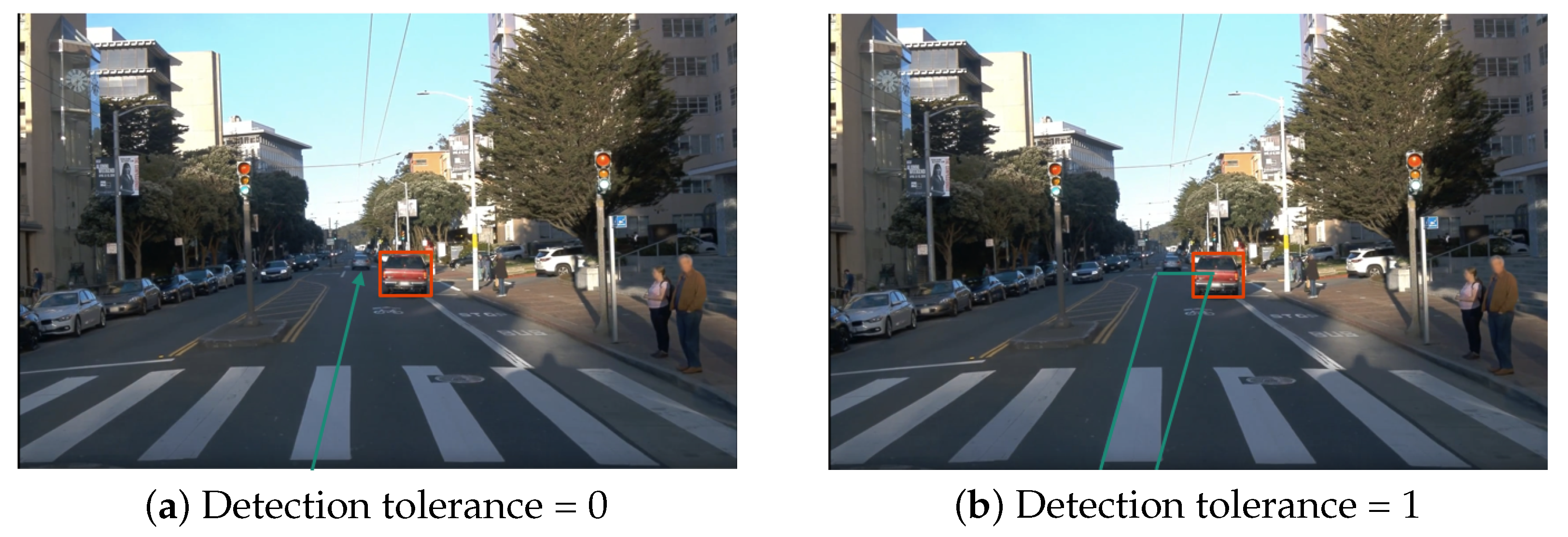
Furthermore, we use a simple geometrical procedure to detect the existence of the front car. As shown in
Figure 1, the procedure checks if a hypothetical ray (green) starting from the position of the AV intersects with the front car (the red bounding box). However, one defect is that there could be many misses by using a single ray. Therefore, we optimize this procedure by utilizing a rectangular ray to represent the AV’s view with some detection tolerance. As a result, the following quantities are extracted as part of the features: velocity (
) and acceleration of the front car (
) and the relative distance to the front car (
). Additionally, enlarging the tolerance range may lead to detection mistakes when there are multiple vehicles ahead, thus the number of vehicles is also included to describe the complexity of the scenario, which is denoted as
. For frames where the front car is not detected, the previously mentioned quantities are set to 0.
In total, 12 features are calculated as mentioned above and will be used in our experiments.
Table 1 shows the features with corresponding explanations.
3.6. Image Embedding
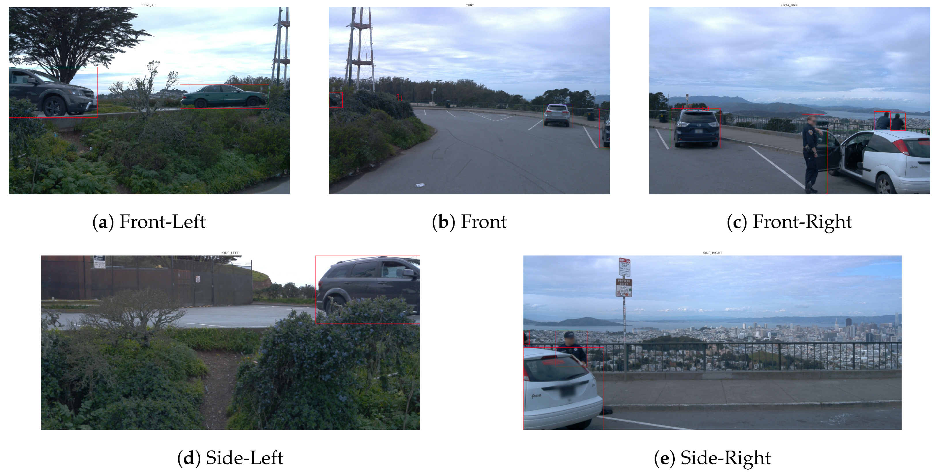
As shown in
Figure 2, there are five cameras installed on each Waymo car, facing towards
front, front-left, front-right, side-left, and side-left, respectively. These images reflect the time-series information of the moving vehicle with relatively smoother dynamics than numerical data, which helps to prevent spiky prediction between consecutive frames. Therefore, we utilize image embedding, a concise representation (vector) of images, as a part of input data to train the models. More details of image embeddings will be discussed in the LSTM-based model section.
4. Baseline Models
In order to establish benchmarks for comparison, we propose several baseline models using different methods including neural network models and decision-tree-based ensemble methods. In this section, we focus on the structures and principles of the baseline models. By default, we use Mean Square Error (MSE) as the loss function for training.
4.1. Neural Network Models
NN: Since the numeric and image data can both represent the surroundings and affect the decisions made by the AV, the first baseline model is a simple deep neural network that takes 12 features as input and owns two hidden layers with eight and four neurons, respectively. This model aims at capturing the characteristic of the 12 features, as well as the relationship between accelerations and the surrounding environment.
CNN: The second model is a traditional convolutional neural network with convolutional, batch normalization, and pooling layers. Grid search is applied to determine the optimal parameters during training. Video images of each frame in the dataset are used as inputs to predict the acceleration of the same frame. Then, the output of the multiple layers is fed into dense layers to extract feature embedding of the image and generate the output.
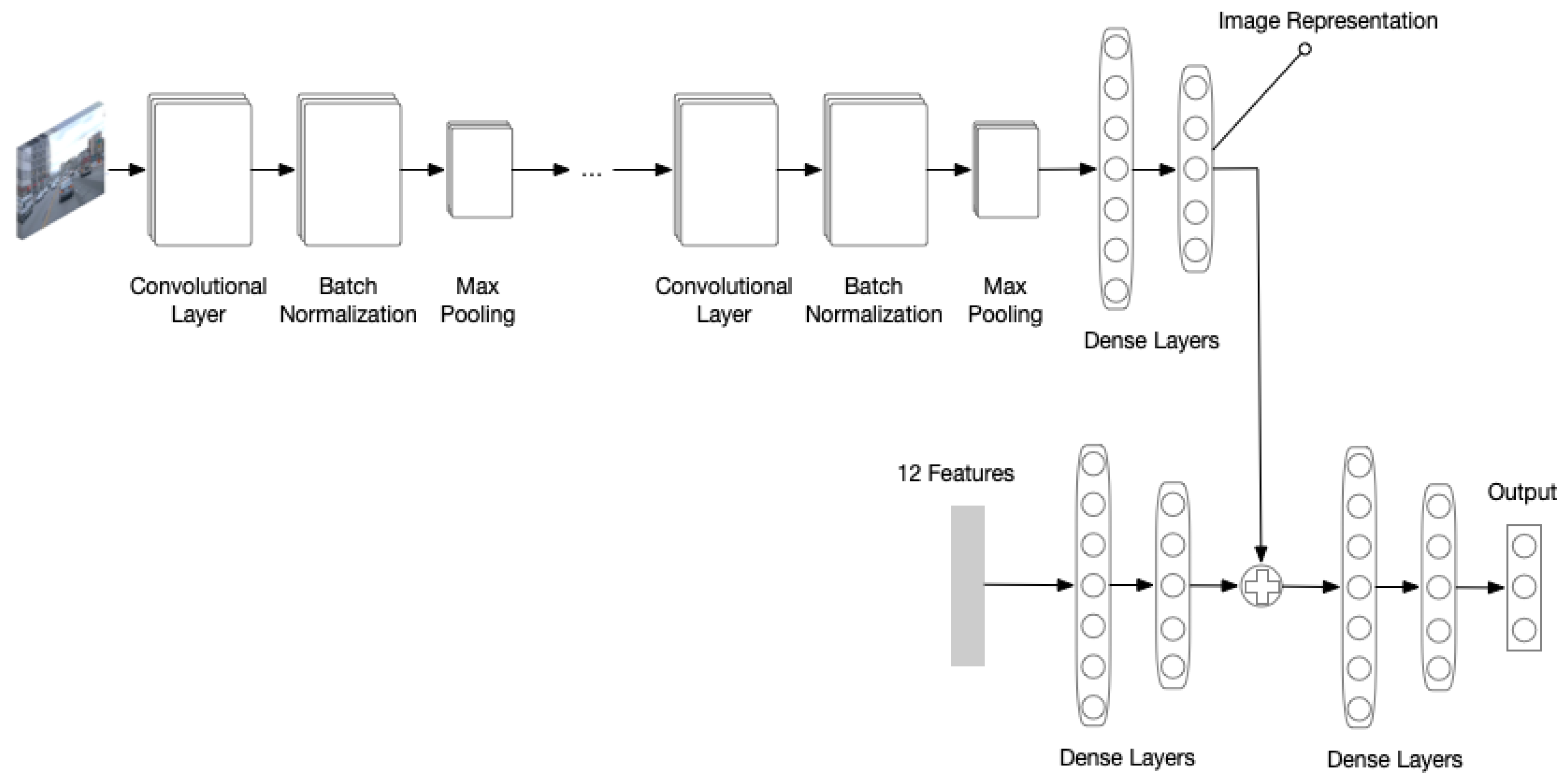
NN + CNN: To better represent a frame using the image embedding as well as the 12 features corresponding to a frame, the third model combines the NN and CNN models. Specifically, as shown in
Figure 3, the last dense layers of both models are concatenated to new dense layers that eventually generate the final output.
4.2. Ensemble Methods
Another popular category for regression problems is the ensemble methods. For a thorough exploration of the dataset, we attempted several ensemble methods and compare their prediction results:
5. LSTM-Based Model
5.1. Basic Model with 12 Features
One of the straightforward ways to build the acceleration prediction model is to treat 12 basic features as the input of the model. The “encoder–decoder” architecture proposed for trajectory prediction in SS-LSTM [
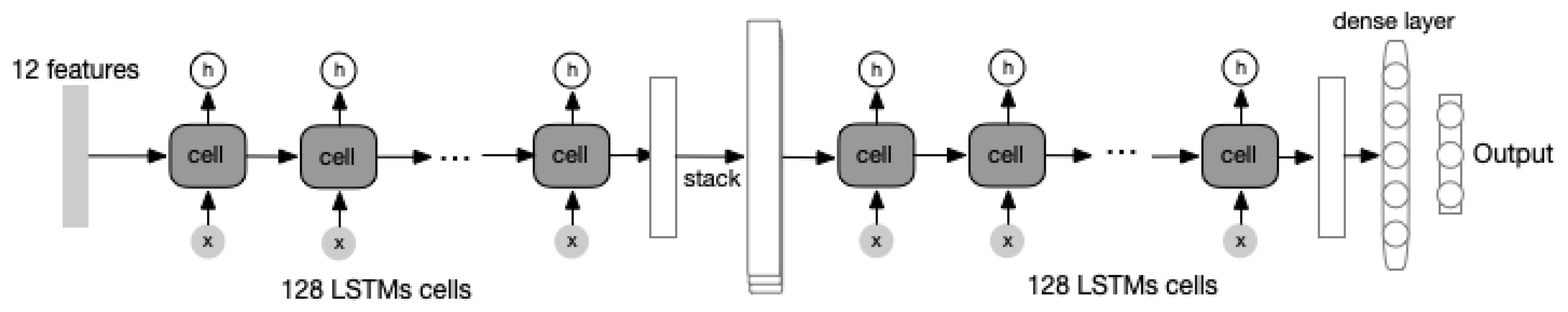
15] is a suitable architecture for the acceleration prediction problem as the acceleration curve is a trajectory based on past experiences. While SS-LSTM uses different input information such as the occupancy map, the 12 basic features are packed into one single input channel in our proposed basic model. These features are fed into an “encoder” module and this “encoder” extracts the key information from input features and generates an intermediate result, or more precisely, a latent representation of these features. The intermediate result is then forwarded into a “decoder” module, which decodes the representation and outputs the acceleration prediction. The figure of this architecture is shown as
Figure 4.
However, the limitation of information provided by the 12 input features cannot be ignored. It is difficult for the model to capture and analyze the complex surrounding environment for the AV by these simple and limited numerical features, and the model trained on these features may fail to give a satisfying prediction. High-quality features with more key information are needed to improve the model capacity.
5.2. Advanced Model with Image Inputs
Given the limitation of the basic model, more features from the Waymo Open Dataset should be incorporated and one of the most critical data that can be used is the camera image, which perfectly records the changing environment of the AV. It is obvious that a raw camera image cannot be fed into the basic model directly as an image is a two-dimensional data point while the input is required to be a one-dimensional vector. Thus, converting the raw image into a vector whose elements represent the key content of the image is necessary.
Naturally, CNN is a popular and excellent image feature extractor that converts an image into a flatten vector. We add one CNN in front of the “encoder” module. Training the CNN module with the “encoder” module and the “decoder” module as a whole can yield an end-to-end advanced model, much more complex than the basic model. However, training this model from scratch can be time-consuming because of the complexity of a deep CNN module. One quick but efficient solution is to use a pre-trained CNN module to convert the raw image into a vector without any fine-tuning, as the existing popular pre-trained CNN networks are mostly well trained on massive datasets and should generalize well. One of the best CNN networks is the ResNetV2 [
9] and the output of its second last layer can be a high-quality representation of the input image. With such an image feature extractor, we decide to use the front camera image in the Waymo Open Dataset as the major input because this camera captures the most critical environment of an AV and contains key information to determine its future acceleration. In other words, image embedding receives and processes inputs from a front camera through the ResNetV2 and outputs an embedding result:
where
is the 1576-dimensional embedding result,
is the ResNetV2 model with the second last layer as its output,
is the parameter for the pretrained ResNetV2.
With the embedding image and the 12 basic features, the idea of the advanced model can be illustrated by this equation:
where
is a three-dimensional output containing accelerations along the
x-axis, the
y-axis, and the
z-axis,
is the embedding image,
and
is the proposed advanced model with its parameter
.
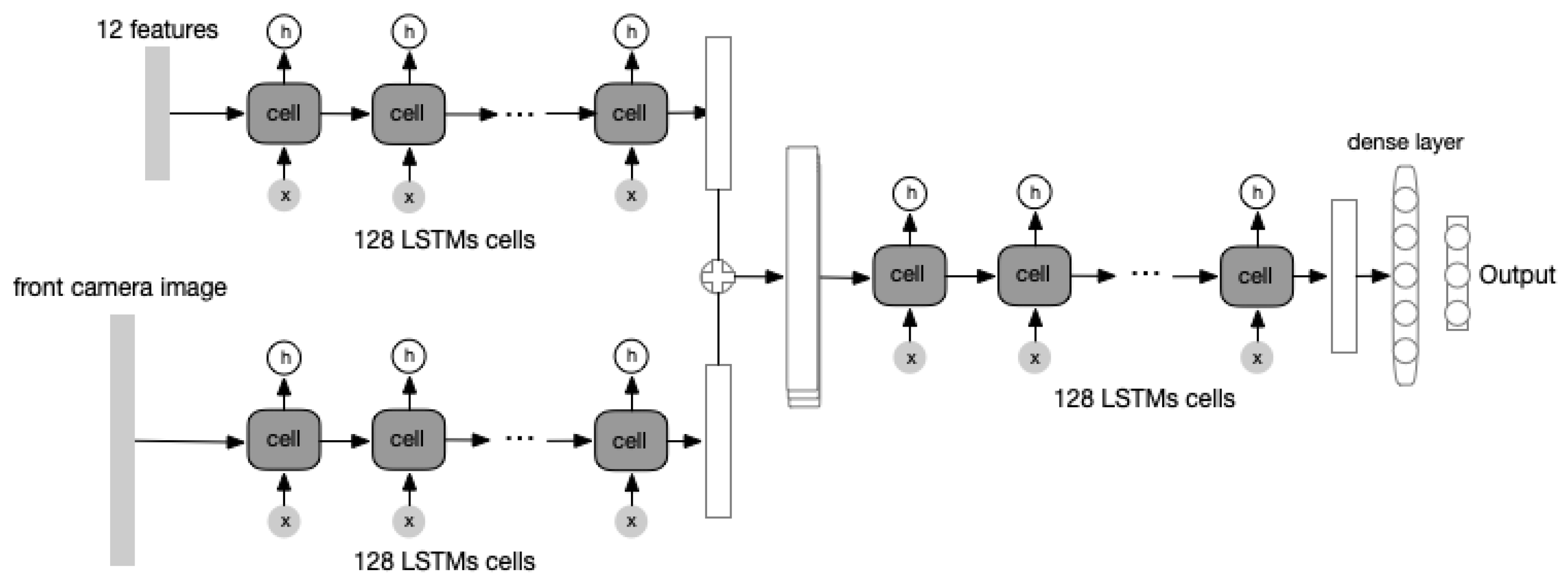
The architecture of such an advanced model is similar to the previous basic model. An “encoder–decoder” structure is maintained to learn the information hidden in the input features. The difference is that the front camera images are treated as additional inputs. The detail of this architecture is shown as
Figure 5.
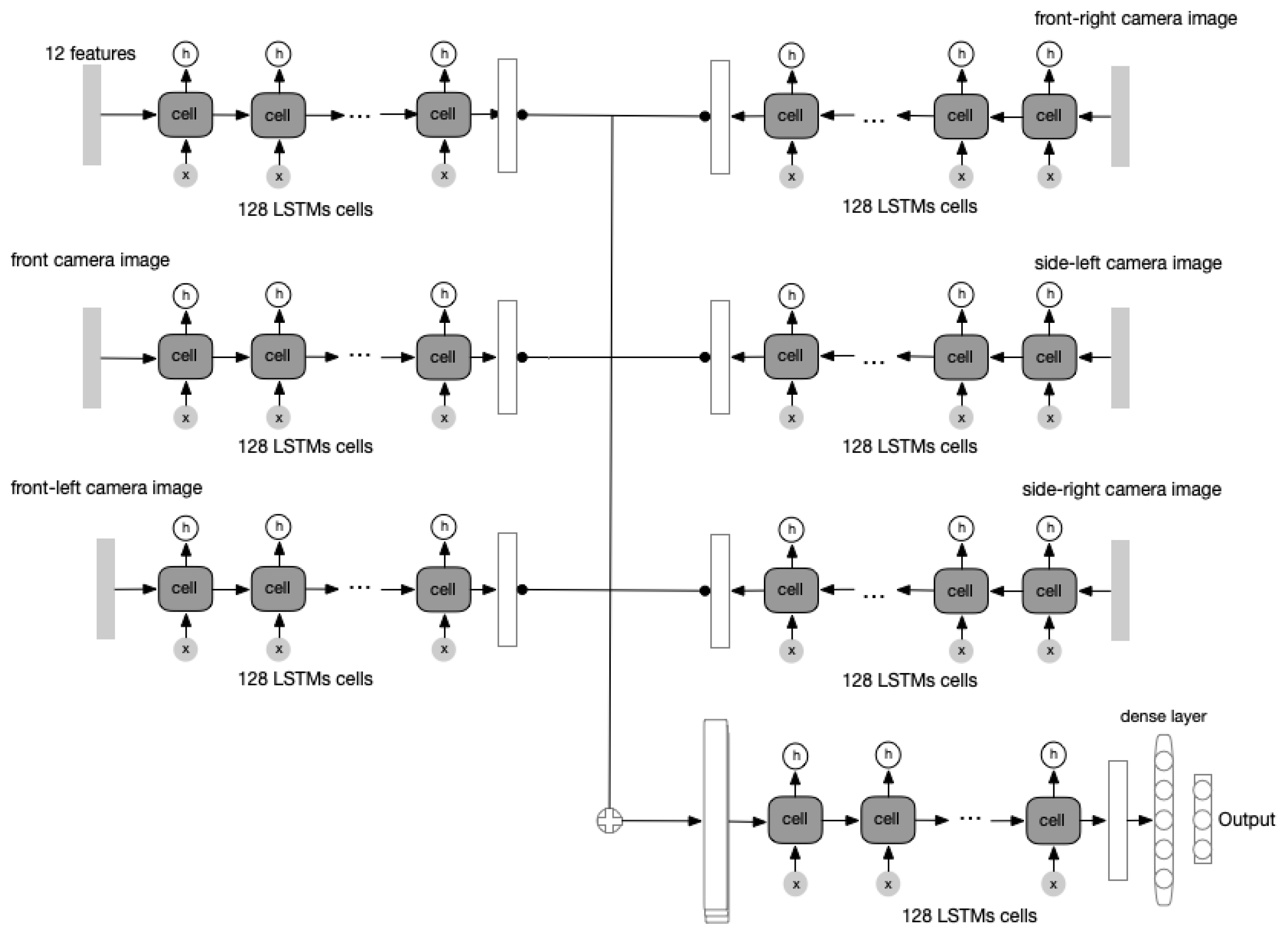
In the Waymo Open Dataset, cameras from five different views are provided, which are the front camera, the front-left camera, the front-right camera, the side-left camera, and the side-right camera, respectively. We believe that incorporating all these five cameras can obtain a more advanced model than the previously trained models. The module architecture of the model is similar and the only change is to add four extra input channels for the rest of the four cameras in addition to the front camera. The architecture of this model is shown as
Figure 6.
6. Experiments and Results
Each model is evaluated on the same test data sampled from the Waymo Open Dataset. To determine the accuracy of acceleration prediction from the trained model, Mean Absolute Error (MAE) is used as the major metric. The MAE value is calculated by taking the average on all MAE errors of the video clips from the test data. The major advantage of using MAE as metric is that, for most frames, the acceleration values are small as the AV is moving steadily on highways or roads, and the absolute values are usually below one. MAE maintains the difference between the predicted and true values and helps us determine which model performs better. Using other metrics, such as MSE, as the metric, however, may further shrink those extremely small values due to the squared sum, leading to insufficient differences in model comparison. VM instance from Google Cloud Platform is used to train all models mentioned and the VM has one single NVIDIA Tesla K80.
6.1. Hyper-Parameter
In the experiments, the major hyper-parameters are the following:
The length of the previous frames This decides how much the model can see in the history. If the length is too short, the model may perform poorly as it could not obtain enough history to predict accurately. If the length is too long, the model is too complex and waste resources. We set this number to 10.
The length of the future frames This decides how much the model needs to predict for the future. If the length is too long, the model is too complex and needs more history to support good prediction. We set this number to 5.
training epochs We set this to 300 in order to obtain a well-trained model.
6.2. Results
From
Table 2, the model using 12 features and the front camera image has outperformed most of the other models, and it is proved that adding an image has pushed the model performance to another level compared with the one only using the 12 basic features. However, the model with all cameras has similar performance with the model using only the front camera, which is not consistent with the previous assumption. The reason why the five-camera model failed to perform even better is that the rest of the camera image is noisy input for the model and may likely interfere with information from the front camera, resulting in a slight decrease of the model performance.
6.3. Training Efficiency
The time efficiency of different models is also evaluated during the experiments. From
Table 3, it is obvious that adding images will lead to the rapid growth of training time due to the increase of the model complexity. When all five camera images are introduced into the input data, training takes much more time than only using front camera images. However, the previous result has shown that the difference between the performance of the model using only the front camera and that using all cameras is small. Thus, it is more reasonable to only use the front camera image as the image input because it is more computationally efficient than using images from all five cameras.
6.4. Visualization
To visually inspect how well our model performs, we provide a visualization tool, which takes the predicted accelerations and raw camera images as the input, and generates a video as the output.
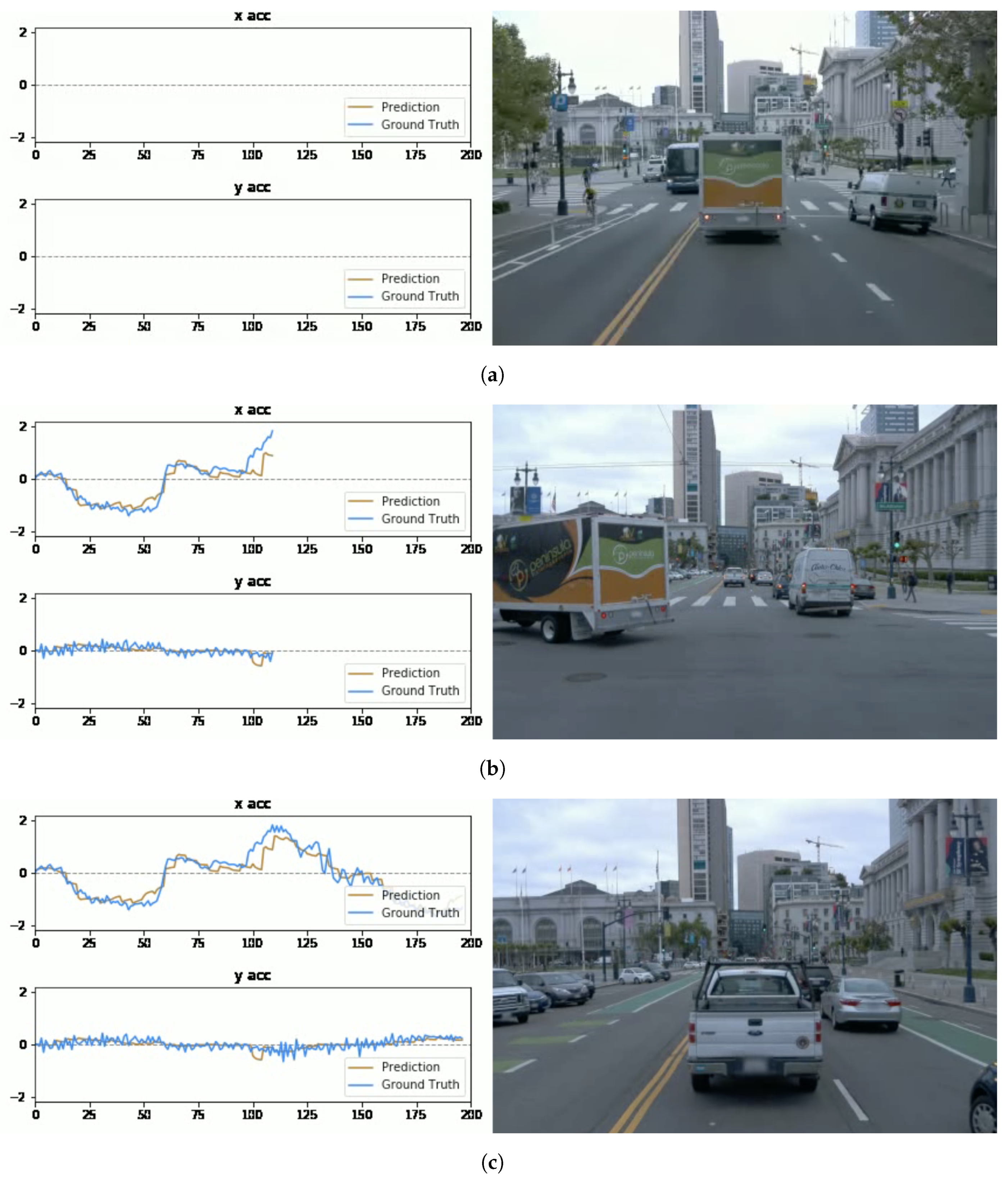
In the three data plots of
Figure 7, the horizontal axis represents the frame index of the segment, while the vertical axis means the acceleration value. The ranges of the vertical axes are all limited to
to prevent misinterpretations. The generated video shows both predicted and ground-truth values (shown as “
prediction” and “
ground truth” in the legends) for longitudinal and lateral accelerations (marked as “
x acc” and “
y acc”, respectively). Combining the data plot (left) and actual video frames (right) gives us an intuitive way to inspect prediction deviation within a continuous spatial and temporal range.
In terms of driving situations, we analyze visualized results of three common scenarios.
The “car-following” scenario: In the dataset, the “car-following” is the most common driving scenario, where the AV maintains a safe distance from the front car and moves at a relative constant speed. As shown in
Figure 7a, the current AV follows the truck in front steadily. The acceleration trend changes accordingly with the speed variation of the truck. Comparing with other scenarios, “car-following” is the scenarios where the prediction curve is closest to the ground-truth curve.
The “front car-turning” scenario: In the 108th frame, the front car makes a turn, the current AV accelerates since there is no leading vehicle blocking the lane ahead. Both the ground-truth and predicted accelerations climbs, while the prediction curve climbs to a lower maximum value. The corresponding visualization is in
Figure 7b.
The “deceleration” scenario: The deceleration happens when the AV detects that the front car decelerates or stops due to the traffic. The model generates negative acceleration values to maintain the safe distance.
Figure 7c shows the corresponding visualization.
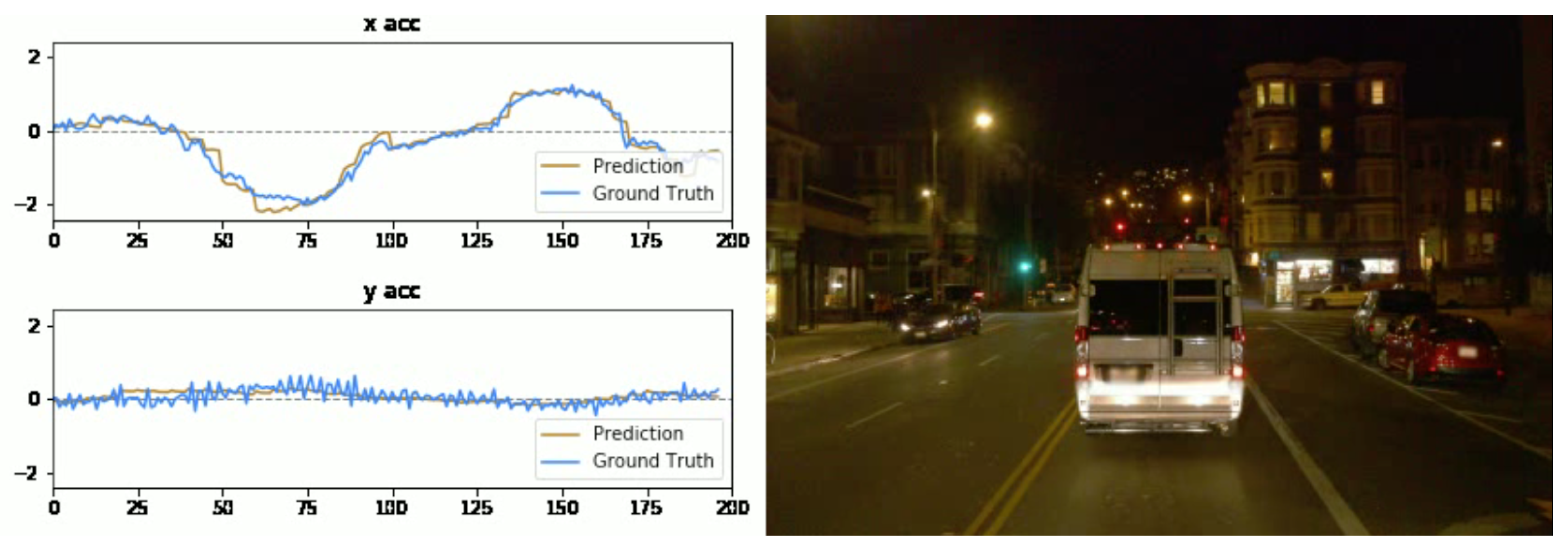
When it comes to lighting conditions, there are other complicated scenarios such as nighttime, rainy days, and so on.
Figure 8 shows an example of driving during nighttime; the overall trend of the prediction curve varies similarly to the ground-truth curve, which helps to hold the prediction loss at a low level. This proves our model’s capability of handling more complex sight conditions in different scenarios. In conclusions, our model behaves very similarly to Waymo’s self-driving policies, in spite of a little more conservativesness in acceleration and deceleration prediction than Waymo’s model.
6.5. Discussion
We would like to discuss several limitations of our model. First, the hyperparameters associated with observed frame lengths (currently 10) and prediction frame lengths (current 5) may limit the capacity of our model. For example, if we only observe three frames, the model may fail to predict well on the following frames due to the lack of information. This means that the current model only allows the input length of 10. Second, our model is trained only using front-camera images from Waymo cars and may not be easily generalized to other car models whose cameras are mounted with different heights and angles. For example, if an AV manufactured by other companies has its front camera positioned a bit higher than that on Waymo’s, our model may not perform well. Thus, the transferrability of our model needs to be further studied.
7. Conclusions and Future Work
From the experimental results, it is observed that the LSTM-based model has better performance than the baseline models, which also supports our assumption that the acceleration prediction is a time-series problem. Inspired by the architecture of LSTM, the "encoder–decoder” structure is adopted in all LSTM-based models. At first, only the basic numeric features such as velocity and distance between the front car and the current AV are used to train the model. Such an LSTM-based model has already outperformed the baseline models without using CNN or those considering time-dependency in the data. To further increase the model performance, camera images are introduced to help the model output a more accurate result. The result shows that the LSTM-based model with an image has significant improvement. However, the model using the front camera only shares similar performance with the model using all five cameras while the latter took a much longer time to train. Therefore, we conclude that the LSTM-based model with the front camera images is an effective and efficient model for acceleration prediction.
This work can be extended in several ways. One limitation of the experiments we carried out is that, in the current training and testing process, the “online approach” takes the ground truth relative distance and velocities as input to the network after predicting the first frame after the initial 10 frames. However, in the scenario of the real world, the input should be taken from (or accumulated from) the prediction of previous frames. Therefore, our current approach may cause the loss to accumulate continually. To solve this problem, our future work is to generate predictions of one frame immediately after the initial ten frames, and then compute the loss between that specific frame and the ground truth data. Another future direction is to train a more generalizable model for other traffic scenarios than car-following—for example, lane-changing, merging and diverging.
Author Contributions
Conceptualization, X.D. and R.S.; Methodology, R.S. and X.D.; experimental design, Z.L., Z.G. and R.S.; software, Z.L. and Z.G.; analysis, Z.L., Z.G. and R.S.; writing, original draft preparation, Z.L. and Z.G.; writing, review and editing, R.S. and X.D.; supervision, X.D.; and funding acquisition, X.D. All authors have read and agreed to the published version of the manuscript.
Acknowledgments
We would like to express our great gratitude to other collaborators who have contributed to this work. We would like to thank Qian Zheng, Gerardo Antonio Lopez Ruiz, and Yumeng Jiang for featuring engineering at an early stage, coming up with the definitions of the “12 features” on which the models were trained on, as well as developing and testing several baseline models such as the XGBoost method and so on. We also appreciate explorations made by Aashish Kumar Misraa, Naman Jain, and Saurav Singh Dhakad about including camera images into the training data, which greatly broadened our scope of mind. In addition, we thank Siddhant Gada and Aditya Das for implementing other neural network baseline models for comparison purposes.
Conflicts of Interest
The authors declare no conflict of interest.
References
- Waymo Open Dataset. Available online: https://waymo.com/open/ (accessed on 14 February 2020).
- Sun, P.; Kretzschmar, H.; Dotiwalla, X.; Chouard, A.; Patnaik, V.; Tsui, P.; Guo, J.; Zhou, Y.; Chai, Y.; Caine, B.; et al. Scalability in Perception for Autonomous Driving: Waymo Open Dataset. arXiv 2019, arXiv:1912.04838. [Google Scholar]
- Bojarski, M.; Del Testa, D.; Dworakowski, D.; Firner, B.; Flepp, B.; Goyal, P.; Jackel, L.D.; Monfort, M.; Muller, U.; Zhang, J.; et al. End to end learning for self-driving cars. arXiv 2016, arXiv:1604.07316. [Google Scholar]
- Krizhevsky, A.; Sutskever, I.; Hinton, G.E. Imagenet classification with deep convolutional neural networks. In Proceedings of the Twenty-sixth Annual Conference on Neural Information Processing Systems (NIPS), Lake Tahoe, NY, USA, 3–8 December 2012; pp. 1097–1105. [Google Scholar]
- Deng, J.; Dong, W.; Socher, R.; Li, L.J.; Li, K.; Li, F.F. Imagenet: A large-scale hierarchical image database. In Proceedings of the 2009 IEEE Conference on Computer Vision and Pattern Recognition, Miami, FL, USA, 20–25 June 2009; pp. 248–255. [Google Scholar]
- Simonyan, K.; Zisserman, A. Very deep convolutional networks for large-scale image recognition. arXiv 2014, arXiv:1409.1556. [Google Scholar]
- Szegedy, C.; Liu, W.; Jia, Y.; Sermanet, P.; Reed, S.; Anguelov, D.; Erhan, D.; Vanhoucke, V.; Rabinovich, A. Going deeper with convolutions. In Proceedings of the IEEE Conference on Computer Vision and Pattern Recognition, Boston, MA, USA, 7–12 June 2015; pp. 1–9. [Google Scholar]
- He, K.; Zhang, X.; Ren, S.; Sun, J. Deep residual learning for image recognition. In Proceedings of the IEEE Conference on Computer Vision and Pattern Recognition, Las Vegas, NV, USA, 27–30 June 2016; pp. 770–778. [Google Scholar]
- He, K.; Zhang, X.; Ren, S.; Sun, J. Identity mappings in deep residual networks. In Proceedings of the European Conference on Computer Vision, Amsterdam, The Netherlands, 11–14 October 2016; pp. 630–645. [Google Scholar]
- Liao, S.; Zhou, L.; Di, X.; Yuan, B.; Xiong, J. Large-scale short-term urban taxi demand forecasting using deep learning. In Proceedings of the 2018 23rd Asia and South Pacific Design Automation Conference, Jeju rIsland, Korea, 22—25 January 2018; pp. 428–433. [Google Scholar]
- Pascanu, R.; Mikolov, T.; Bengio, Y. Understanding the exploding gradient problem. arXiv 2012, arXiv:abs/1211.5063. [Google Scholar]
- Cho, K.; Van Merriënboer, B.; Gulcehre, C.; Bahdanau, D.; Bougares, F.; Schwenk, H.; Bengio, Y. Learning phrase representations using RNN encoder-decoder for statistical machine translation. arXiv 2014, arXiv:1406.1078. [Google Scholar]
- Ullah, A.; Ahmad, J.; Muhammad, K.; Sajjad, M.; Baik, S.W. Action recognition in video sequences using deep bi-directional LSTM with CNN features. IEEE Access 2017, 6, 1155–1166. [Google Scholar] [CrossRef]
- Alahi, A.; Goel, K.; Ramanathan, V.; Robicquet, A.; Li, F.F.; Savarese, S. Social lstm: Human trajectory prediction in crowded spaces. In Proceedings of the IEEE Conference on Computer Vision and Pattern Recognition, Las Vegas, NV, USA, 27–30 June 2016; pp. 961–971. [Google Scholar]
- Xue, H.; Huynh, D.Q.; Reynolds, M. SS-LSTM: A hierarchical LSTM model for pedestrian trajectory prediction. In Proceedings of the 2018 IEEE Winter Conference on Applications of Computer Vision, Lake Tahoe, NV, USA, 12–15 March 2018; pp. 1186–1194. [Google Scholar]
- Mercorelli, P. Using Fuzzy PD Controllers for Soft Motions in a Car-like Robot. Adv. Sci. Technol. Eng. Syst. J. 2018, 3, 380–390. [Google Scholar] [CrossRef] [Green Version]
- Mercorelli, P. Fuzzy based Control of a Nonholonomic Car-Like Robot for Drive Assistant Systems. In Proceedings of the 19th International Carpathian Control Conference (ICCC), Szilvasvarad, Hungary, 28–31 May 2018; pp. 434–439. [Google Scholar]
- Data Description of Waymo Open Dataset. Available online: https://waymo.com/open/data/ (accessed on 14 February 2020).
- Ke, G.; Meng, Q.; Finley, T.; Wang, T.; Chen, W.; Ma, W.; Ye, Q.; Liu, T.Y. Lightgbm: A highly efficient gradient boosting decision tree. In Proceedings of the Thirty-first Annual Conference on Neural Information Processing Systems, Long Beach, CA, USA, 4–9 December 2017; pp. 3146–3154. [Google Scholar]
- Breiman, L. Stacked regressions. Mach. Learn. 1996, 24, 49–64. [Google Scholar] [CrossRef] [Green Version]
Figure 1.
Examples of two different detection tolerances applied to the same scenario, displayed on visualizations of camera images in the Waymo Open Dataset.
Figure 1.
Examples of two different detection tolerances applied to the same scenario, displayed on visualizations of camera images in the Waymo Open Dataset.
Figure 2.
One example of images captured by cameras of five different views from segment-11004685739714500220 of tar training_0000 in the Waymo Open Dataset.
Figure 2.
One example of images captured by cameras of five different views from segment-11004685739714500220 of tar training_0000 in the Waymo Open Dataset.
Figure 3.
The composited model of NN and CNN. The CNN module uses similar architecture as VGG16. Each layer consists of three sub-layers: one standard CNN layer with kernel size 5, one batch normalization layer with batch size 32 and one max pooling layer. The last two layers are dense layers with 100 hidden units and 50 hidden units, respectively. Notice that the output of the last dense is the trained representation of the input image. The NN module is a simple two-layer neural network with 100 hidden units and 50 hidden units. The outputs of the NN module and CNN module are concatenated to form new dense layers that generate the final acceleration output. The hidden sizes of the last two layers are 100 and 50.
Figure 4.
The basic architecture is relatively straightforward as only 12 features are provided. The information is first encoded by the “encoder” module and an intermediate latent vector, which contains the key value as well as the relationship between the elements, is produced. Then, this vector is stacked in order to match the prediction frame numbers and fed to the “decoder” module and generated a new representation of the original input. The new representation is used to train the final dense layer to predict the acceleration. Given one video clip with a frame-length of 10, the input is the vector consists of 12 features from these 10 frames. The output is the acceleration for the next five frames starting from the end of the video clip. The “encoder” module contains 128 LSTM-cells and the “decoder” module contains 128 LSTM-cells. The optimizer of this network is RMSprop with learning rate 0.0001 and the dropout is used for each LSTM-cell with probability 0.2.
Figure 5.
Notice that the “image” input is a vector containing key image contents. The first channel input is the 12 features for the observed 10 frames. The second channel input is the 1576-dimensional representation of front camera images from these 10 frames. Such representation is extracted from the second last output of a pre-trained Resnet152v2. The outputs from both channels are concatenated to form a representation with information from the features and image contents. The representation is stacked and fed in the same way as the basic model. The output is the acceleration for the future five frames. The “encoder” module contains 128 LSTM-cells and the “decoder” module contains 128 LSTM-cells. The optimizer of this network is RMSprop with learning rate 0.0001 and the dropout is used for each LSTM-cell with probability 0.2.
Figure 6.
The first channel input is the 12 features for the observed 10 frames. The rest of the input is the 1576-dimensional representation of camera image from different views in the observed 10 frames. The outputs from all channels are concatenated to generate a representation that contains all information and key contents. The representation is stacked and fed in the same way as the basic model. The “encoder" module contains 128 LSTM-cells and the “decoder” module contains 128 LSTM-cells. The optimizer of this network is RMSprop with a learning rate 0.0001 and the dropout is used for each LSTM-cell with probability 0.2.
Figure 7.
Key frames representing three different scenarios, all are extracted from segment-10289507859301986274 from tar validation_0001. (a) In the first frame of the video, this is a typical “car-following” scenario: the AV follows the truck steadily, and the initial value of the acceleration is around zero; (b) In the 108th frame of the video, the truck turns left and, at this moment, there is no detected front car and the AV accelerates. The ground-truth and the prediction acceleration curves climb simultaneously; (c) In the last frame of the video, the declining acceleration curves show that the AV brakes accordingly as the front car stops due to the traffic ahead.
Figure 8.
Model prediction with synchronized frames captured by the front-camera on the right.
Figure 8.
Model prediction with synchronized frames captured by the front-camera on the right.
Table 1.
The 12 features computed from the data of Waymo Open Dataset.
Table 1.
The 12 features computed from the data of Waymo Open Dataset.
| Features | Explanations |
|---|
| The velocity of AV in directions. |
| The distance from AV to the front car in directions. |
| The velocity of front car in directions. |
| The acceleration of front car in directions. |
| The number (existence) of front vehicles, which describes the complexity of the scenario. |
Table 2.
MAE comparison. Compared with the values along the x-axis and the y-axis, the values along the z-axis are small enough to be ignored; thus, the MAE result along the z-axis is omitted.
Table 2.
MAE comparison. Compared with the values along the x-axis and the y-axis, the values along the z-axis are small enough to be ignored; thus, the MAE result along the z-axis is omitted.
| Models | MAE X | MAE Y |
|---|
| NN | 0.4014 | 0.4312 |
| CNN | 0.3272 | 0.3123 |
| NN + CNN | 0.2985 | 0.2802 |
| XGBoost | 0.3502 | 0.3537 |
| Light Gradient Boosting | 0.3459 | 0.3444 |
| Stacked Linear Regressor | 0.3623 | 0.3222 |
| LSTM with 12 features | 0.3179 | 0.3088 |
| LSTM with front camera | 0.1379 | 0.1278 |
| LSTM with all cameras | 0.1327 | 0.1363 |
Table 3.
Approximate training time of different models.
Table 3.
Approximate training time of different models.
| Model | Approximated GPU Training Time |
|---|
| LSTM with 12 features | 1.8 h |
| LSTM with front camera | 9.0 h |
| LSTM with all cameras | 37.8 h |
© 2020 by the authors. Licensee MDPI, Basel, Switzerland. This article is an open access article distributed under the terms and conditions of the Creative Commons Attribution (CC BY) license (http://creativecommons.org/licenses/by/4.0/).


