Article

Broadband Wireless Communication Systems for Vacuum Tube High-Speed Flying Train

1
School of Electronic and Information Engineering, Beijing Jiaotong University, Beijing 100044, China
2
The Center of National Railway Intelligent Transportation System Engineering and Technology, China Academy of Railway Sciences, Beijing 100081, China
*
Author to whom correspondence should be addressed.
Appl. Sci. 2020, 10(4), 1379; https://doi.org/10.3390/app10041379
Submission received: 4 January 2020 / Revised: 2 February 2020 / Accepted: 14 February 2020 / Published: 18 February 2020
(This article belongs to the Special Issue Intelligent Transportation Systems: Beyond Intelligent Vehicles)

Abstract

:
A vactrain (or vacuum tube high-speed flying train) is considered as a novel proposed rail transportation approach in the ultra-high-speed scenario. The maglev train can run with low mechanical friction, low air resistance, and low noise mode at a speed exceeding 1000 km/h inside the vacuum tube regardless of weather conditions. Currently, there is no research on train-to-ground wireless communication system for vactrain. In this paper, we first summarize a list of the unique challenges and opportunities associated with the wireless communication for vactrain, then analyze the bandwidth and Quality of Service (QoS) requirements of vactrain’s train-to-ground communication services quantitatively. To address these challenges and utilize the unique opportunities, a leaky waveguide solution with simple architecture but excellent performance is proposed for wireless coverage for vactrains. The simulation of the leaky waveguide is conducted, and the results show the uniform phase distribution along the horizontal direction of the tube, but also the smooth field distribution at the point far away from the leaky waveguide, which can suppress Doppler frequency shift, indicating that the time-varying frequency-selective fading channel could be approximated as a stationary channel. Furthermore, the train-to-ground wireless access architectures based on leaky waveguide are studied and analyzed. Finally, the moving scheme is adopted based on centralized, cooperative, cloud Radio Access Network (C-RAN), so as to deal with the extremely frequent handoff issue.

1. Introduction

The rise of High Speed Railway (HSR) around the world enables a faster, safer, and cheaper transportation system that caters for the demand of numerous passengers. However, the further development of HSR is mainly constrained by the three factors: resistance between wheel and rail, resistance of the air, and aerodynamic noise. The measured data reveals that when the velocity of the train reaches up to 400 km/h, the resistance of the air will account for more than 80% of the train traction, causing a large waste of energy. As a consequence of the above three constraints, the critical velocity of HSR is 600 km/h [1].
With the rapid development of HSR, the next generation of ultra-high-speed transportation technology—vactrain, has gradually come to people’s attention. The vactrain is a magnetically levitated or magnetically powered train system, which operates inside the evacuated or partly evacuated (air-less) tubes. As mentioned above, aerodynamic drag is the dominant factor hindering speedup of HSR. Therefore, the reduced air resistance could permit vactrain to travel at very high speeds with relatively little power up to 1000–4000 km/h, or 5–6 times the speed of sound (Mach 1) at standard conditions.
The concept of vacuum tube transportation was first proposed by Robert Goddard, the father of modern rockets, in 1904 [1]. In 2013, Elon Musk, the CEO of Tesla and SpaceX, published a white paper called “Hyperloop Alpha“, proposing the hyperloop technology based on the vactrain concept [2]. At present, significant research efforts are underway to promote the practical application of vacuum tube transportation in China and the United States. On 12 May 2016, Hyperloop One, an American vacuum tube transportation company, first comprehensively tested the propulsion system of hyperloop [3]. In 2018, another US vacuum tube rail developer, Hyperloop Transportation Technologies (HTT), announced plans to build hyperloop lines in Toulouse, France and Tongren, Guizhou, China [4,5]. In 2017, China Aerospace Science and Industry Corporation (CASIC), the country’s state-run space contractor, announced that they has initiated research on project of vacuum tube high-speed flying train [6].
At present, almost no research is available on train-to-ground communication for vactrain according to the published results. Thus, the wireless communication technologies that have been studied or applied in the railway systems will be first reviewed. The current wireless communication technologies applied to railway systems mainly include GSM for Railway (GSM-R), LTE-R (LTE for railways), Wireless Local Area Networks (WLANs), LTE for Metros (LTE-M), 38G mm wave technology (Shanghai maglev [7]), etc.
GSM-R aims at the characteristics of train dispatching, train control, and high-speed operation in railway communication [8]. Despite the overwhelming maturity and popularity, GSM-R is on the way out due to the hindrance of increasing interference from public networks and increasing bandwidth requirements. In the future, LTE-R, which is based on the LTE standard, is a likely candidate for GSM-R [9]. The world’s first rail service to support LTE is China’s heavy haul railway from Shenchi to Huanghua [10].
For urban transit rail systems, IEEE 802.11a/b/g/n/ac based on WLANs is currently a prevalent choice due to the available commercial-off-the-shelf equipments [11]. However, WLANs are not specifically designed for high mobility scenarios, and there are some problems for WLAN-based Communications-Based Train Control (CBTC) systems, such as handoff and Quality of Service (QoS) issues [12]. Recently, LTE-M, based on the TD-LTE standard, has been proposed as the communication method in urban transit rail systems. In China, LTE has been adopted as the communication method in the passenger information system of Zhengzhou metro Line 1, which operates in the 1795 to 1805 MHz frequency band [13].
The 38 GHz MilliMeter-Wave (MMW) wireless communication technology is the applied in Shanghai maglev system [7]. The 38 GHz MMW system could provide a capacity reach up to 100 Mbps, but also ensure the delay less than 5 ms and the Bit Error Rate (BER) of safe-related data transmission in the order of 10 - 5 [14]. The mmW communication system is also a candidate for the system offering high-speed communication services in HSTs. Junhyeong Kim and Gyu Kim [15] proposed the DAS-based 28 GHz millimeter-wave mobile communication system for HSTs, and analyzed the potential of the system through the computer simulations, showing that the enormous throughput exceeding 2 Gbps can be achieved in the HST moving at a speed of 400 km/h.
Table 1 summarizes an overall performance comparison of the mentioned wireless technologies in high-speed scenario. However, the maximum supporting speed of these technologies does not exceed 500 km/h, whereas the vactrain operates at a speed exceeding 1000 km/h. In terms of 5G system, Section 6.1.5 of the standardized manuscript 3GPP TR 38.913 [16] clearly indicates that 5G NR supports a maximum speed of 500 km/h. Thus, the current railways communication system based on LTE cannot support the train-to-ground communication for vactrain.
Same as the current HSR [17] and maglev train [7], the train-to-ground wireless communication is crucial for the safe operation of vactrain. The communication system is responsible for providing bidirectional and reliable data transmission channels between the train and ground to meet the specific needs of integrated services transmission [18]. However, due to the two unique features of vactrain— closed metal vacuum tube and ultra-high velocity—the train-to-ground wireless communication for vactrains will be more challenging than that of the current HSR [19] and maglev train. Therefore, a wireless communication system of high reliability and high performance dedicated to scenario of speed exceeding 1000 km/h needs to be investigated, catering for the strong train-to-ground communication demand of vactrain.
The goal of this article is to study wireless communication systems that aim to make wireless access available between the vactrain and ground. The main contributions are listed as follows. (1) We summarized a list of the unique challenges and opportunities associated with the wireless communication for vactrain. (2) The bandwidth and QoS requirements of vactrain’s train-to-ground communication service are quantitatively analyzed and presented. (3) A leaky waveguide is proposed to suppress the severe Doppler frequency shift in high-speed scenario. (4) An electromagnetic lens system is proposed to achieve direct wireless coverage for user equipments inside the train. (5) The moving cell scheme based on the C-RAN architecture is adopted to deal with the issue of extremely frequent handoff.
The structure of this article is as follows. We first reviews wireless communication technologies researched or deployed in the railway systems, then analyze their feasibility for vactrain’s train-to-ground communication. The rest of this paper is laid out as follows. Section 2 summarizes several key challenges of train-to-ground wireless communication for the vactrain. In Section 3, the bandwidth and QoS requirements of vactrain’s train-to-ground communication service are analyzed quantitatively. In Section 4, a leaky waveguide with simple architecture is proposed for the wireless access inside the tube, of which the simulation results show that the severe Doppler frequency shift is restrained largely. Section 5 introduces some solutions to establish wireless link between the train user equipments and leaky waveguide. In Section 6, the moving cell scheme based on the C-RAN architecture is adopted to deal with the issue of extremely frequent handoff. Finally, in Section 7, we provide concluding remarks.

2. Key Challenges of Vactrain’s Wireless Communications

The distinctive scenario of enclosed metal tube and ultra-high terminals’ speed impose numerous challenges on the modeling, design, analysis, and evaluations of the train-to-ground wireless communication systems of vactrain [20]. In the meantime, high mobility and the fully enclosed vacuum tube wall also provide unique opportunities that can be exploited to facilitate system designs and to improve system performance. The key challenges faced by the design of vactrain’s wireless communication, as well as some opportunities that can benefit system designs, are listed as follows.
(1)
Propagation characteristics in the tube: For the design of wireless communications network, the knowledge of the wireless channel, which has a close relationship with propagation scenarios, is the fundamental basis. Different from traditional tunnel scenarios [21,22,23,24], which mainly consists of stone and clay, the vactrains are operating inside the fully enclosed metal tube wall, resulting in the unique propagation environment for wireless signal. From the aspect of waveguide, the concept of “mode“ can be used to analyze the propagation characterization of radio waves in the tube [25,26]. Based on this theory, the high-order mode gradually decays and disappears as the distance between transmitter and receiver increases, only leaving the low-order mode. Due to this reduction of modes, the signal subspace of the Multiple-Input, Multiple-Output (MIMO) channel matrix is decayed, resulting in a decrease in the capacity of the MIMO channel, that is, the keyhole effect [27,28,29]. In addition, if the leaky waveguide is adopted for wireless coverage, the leaky wave propagation coupling characteristics will be completely different. Due to the fully enclosed metal wall, the near-field radiation characteristics and the spatial distribution of the radiation power density will be greatly affected. Besides, the cross sectional shape and size of the metal tube will result in some unique characteristics of the mode distribution.
(2)
Fast and frequent handovers: Handover, or handoff, is the process by which a Mobile Station (MS) maintains its connection active while moving from one cell to another. Due to the ultra-high velocity, the handoff frequency of vactrain will be much higher than the current HSR under the same configuration of network. It is important to remark that the number of handovers on the systems must be minimized. However, the handover times of current railway communication system are in the order of 100 ms to 1 s, which are absolutely unacceptable for vactrain. For instance, a cell coverage radius of 300 m combined with a vactrain speed of 1000 km/h means a handover every 2.25 s, and in combination with a handover time of 1 s, the communication performance loss could reach up to 0.44. Same as HSR systems, the group handover is another problem when dozens of in-train MSs trying to handover at the same time, causing the so-called signaling storm, which greatly increases the handover load of network. Thus, the new handover strategies and algorithms need to be improved to meet the requirements of handovers in vactrain.
(3)
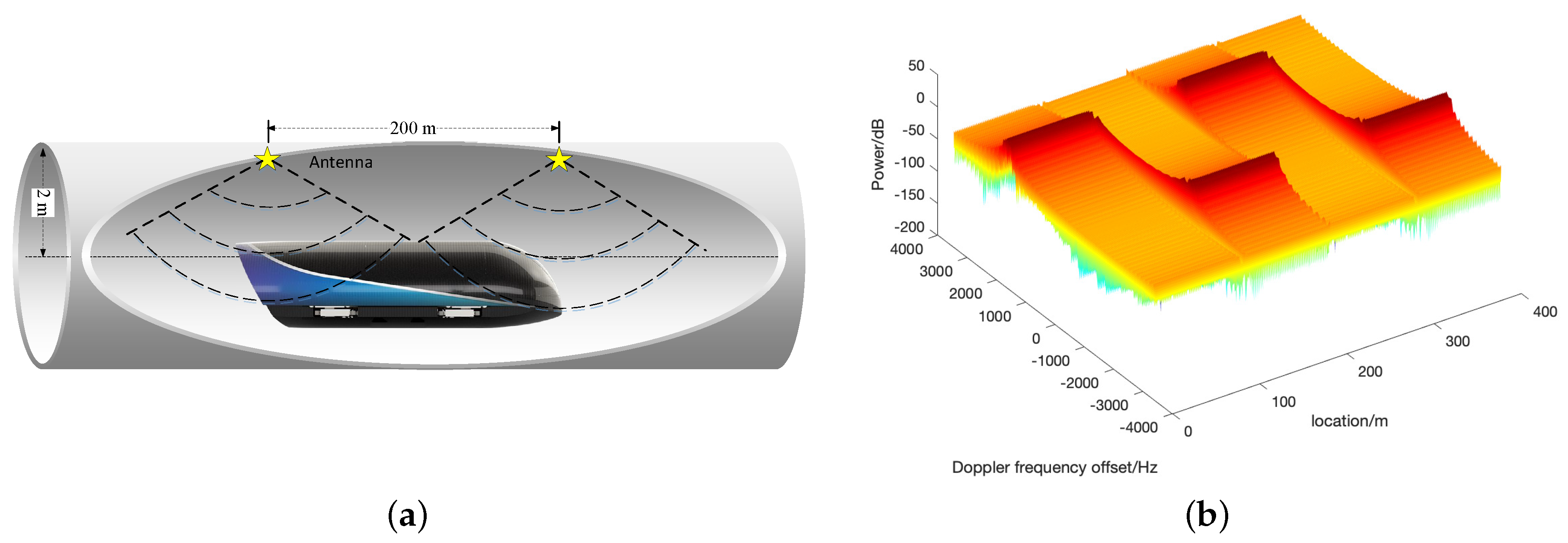
Serious Doppler Frequency shift: When the velocity of the train reaches 1000 km/h, the channel impulse response will change rapidly, experiencing fast fading characteristics [30]. Therefore, the time selectivity is enhanced due to the large Doppler frequency shift and expansion. For example, if the carrier frequency is 3.3 GHz, the maximum Doppler frequency shift is 3055 Hz at a speed of 1000 km/h, whereas the frequency shift for a pedestrian who moves at a speed of 10 km/h is only 24 Hz. Note that most of the current wireless communication systems are designed for the Doppler frequency shift on the order of hundreds of Hz. Due to the high Doppler frequency shift, the carrier frequency offset (CFO) between the transmitter and receiver will occur. However, even for systems without Doppler shifts, small CFO may also occur due to the instability of oscillators in wireless transceivers. Thus, in the multi-carrier systems, such as Orthogonal Frequency Division Multiplexing (OFDM), the large Doppler frequency shift will destroy the orthogonality among the sub-carriers, and introduce the Inter-Carrier Interference (ICI). ICI will seriously degrade the synchronizer performance and increase the system bit error rate. In addition, the movement speeds of the terminals will change with respect to time, resulting in the time-varying Doppler spreads and non-stationary fading coefficients. Thus, the accurate modeling and analysis of high mobility channels inside the vacuum tube will be a challenging task.
(4)
High penetration loss: As is mentioned above, the vactrain is operating in the hermetically sealed vacuum tube. To ensure the air tightness, the tube walls are made of special alloys or reinforced concrete, which are difficult for wireless signals to penetrate. According to the measured date, the penetration loss caused by the train body is usually between 20 dB to 35 dB [31]. Under this superposed penetration losses, the Signal-to-Noise Ratio (SNR) on the received signal in both uplink and downlink will be seriously degraded.
(5)
Frequency spectrum-free environment: The co-channel interference is a serious problem in the current wireless communication for railway. For example, GSM-R in China uses the 883–889 MHz frequency band for the uplink and the 930–934 MHz frequency band for the downlink. This band is shared with services offered by the operator of China Mobile, and thus yield serious co-channel interference. In addition, Wireless Fidelity (WiFi) technology is used in the subway of China for train-to-ground communication and operates at 2.4 GHz [32], which is an unlicensed frequency band, causing serious interference and security problem. However, in scenarios of enclosed metal vacuum tube, the spectrum space in the tube is relatively free from the external environment. Thus, there will be no more the limitation of the frequency and bandwidth for wireless communication in the tube. Based on this, the frequency band and bandwidth can be selected unlimitedly to avoid interference from the user signal and then ensure the stability of wireless transmission of operational signal. Besides, the frequency/ space division multiplexing technologies [33] can also be adopted without limitation to increase the transmission capacity.

3. The Train-to-Ground Wireless Communication Needs

The wireless communication systems of HSR, intercity railway, subway, light rail, and other rail traffic are deployed with various wireless standards. To ensure safe and reliable operation of railways, these wireless standards have to be reliable and robust. Applications such as on-board video surveillance, train control operations, signaling, diagnostics, and monitoring are delay-intensive and complex. In addition, passengers onboard also expect to access Internet for business and entertainment such as on-vehicle video conference, online games, chatting, live broadcast, etc. Train control operations require a lower data rate than passengers’ entertainment needs, but are of significantly higher priority.
Although various wireless communication technologies are adopted in the railway traffic systems, the data transmitted between train and ground are basically identical. These data could be divided into the following categories depending on intended applications, required throughput and railway sectors [18].
(1)
The operational services include
  • the safety-related applications for operation of trains and signaling, also called “Operation Control System” (OCS), which typically integrated with “Traction Control System” (TCS);
  • the robust Operational Voice Communication systems (OVC);
  • Train Operation Status Monitoring data (TOSM);
  • the image transmission for video surveillance: real-time HD video transmissions supporting automatic driving, security Closed Circuit Television (CCTV) in the train; and
  • Passenger Information Service (PIS).
(2)
The services to passengers: it comprises mainly the Internet access on board trains, including business and entertainment such as on-vehicle video conference, online games, chatting, live broadcast, etc.
The classification of services of train-to-ground communication for vactrain is basically identical to that of current railway systems. However, due to the distinguishing characteristics of vactrain, such as vacuum tube wall and ultra-high speed, more stringent transmission requirements for train-to-ground communication are put forward in terms of end-to-end delay and bandwidth. For example, environmental real-time monitoring data (such as air pressure and temperature) of tube and train needs to be transmitted to the ground control center. Besides, due to the ultra-high operation speed, extremely low end-to-end delay and handover delay are required for operational services transmission, such as train location information. Furthermore, real-time High-Definition (HD) video surveillance for the area in front and rear of trains and along the tubes is needed in the virtue of sealed vacuum metal tube. Thus, more HD cameras would be installed inside and outside the train, resulting a higher requirement for throughput.
The amount of data to be transmitted on uplink/downlink and the Key Performance Indicators (KPI), such as end-to-end transmission delay, transmission periodicity, packet loss, or BER, can be used to describe the performance of railway wireless applications. Based on this, Table 2 summarizes the train-to-ground wireless communication performance requirements for urban rail transit (CBTC), HSR, Shanghai maglev trains [14,34,35], as well as the vactrain. The bandwidth and KPI requirements of vactrain’s train-to-ground communication services are analyzed based on the reference to current railway transportation systems, but also the consideration of the extremely high velocity, special operation scenarios and passenger capacity of vactrain.

3.1. The Needs for Operational Services

The operational services, also called critical services, can be divided into two types: those related to the safety of the train itself (operation control system and train traction data) and public safety ones (including OVC, TOSM, CCTV, and PIS). Similar to the HSR, all safety-related services of vactrain need the highest safety level (SIL4 [18]), low bandwidth (less than 1 Mbps per train), extremely significant delay constraints (milliseconds, less than 1 ms in the worst case), and the traffic pattern is usually Real-Time Variable Bit Rate (RT-VBR).
(1)
Operation control systems: Through computer control, computer network, communication and information processing, and other advanced technologies [36,37], the operation control system is connected with the vehicle, traction [38], line, and turnout equipment or system of the maglev transportation system, and ultimately completes the tasks of train operation control, safety protection, automatic operation, and dispatch management. Similar to Shanghai maglev [7], the train operation systems for vactrain mainly consist of three layers: the central control system located in the control center, zone control systems corresponding to the traction section, and on-board control systems located on the train. As a critical service to train operation safety, OCS needs highest priority, end-to-end delay lower than 40 ms, and BER in the order of 10 - 6 to ensure the reliable and robust communication. The bidirectional data transmission between zone control systems and train control systems could be provided by the train-to-ground communication system. These data mainly includes mobile authorization, temporary speed limit information, clock synchronization status, train identification number, etc., which requires the relatively short information coding length and small data size (most of the time less than 100 bytes), resulting in a low bandwidth requirement. Table 2 shows that the OCS bandwidth requirement of current railway transit does not exceed 500 Kbps per train. Thus, considering the higher safety requirements of vactrain, the minimum bandwidth of vactrain OCS could be set to 1 Mbps (up/down).
(2)
Traction Control System: Typically, TCS is integrated with OCS and deployed in the zone control systems which correspond to the traction sections. The TCS and OCS complement each other to ensure the safe operation of vactrain. To fully control the speed of vactrain, the train operational command data, such as velocity–position curve, should be transmitted to TCS from zone control systems through ethernet network. In addition, the magnetic pole phase angle data, which contains the train positioning information, needs to be transmitted from on-board control systems to TCS directly through the train-to-ground wireless links. This real-time train location information is the basis of automatic train driving, but is also an indispensable part of synchronous linear motor control and train interval control. Due to the vactrain’s ultra-high velocity, the transmission of train positioning information needs to meet the requirement of extreme low end-to-end delay [39]. As shown in Table 2, the TCS of Shanghai maglev train (430 km/h) needs the transmission delay of train-to-ground wireless communication less than 5 ms [14]. Assuming that the speed of vactrain exceeds 1000 km/h, and the transmission delay is inversely proportional to the speed, the transmission delay requirement for TCS of vactrain is less than 1 ms.
(3)
The robust operational voice communication systems: These systems allow not only trains to communicate with the rail traffic control centers, but also trains drivers, rail traffic, and maintenance agents to communicate with each others in conference mode (group calls). Besides, the train broadcasting function needs to be supported by OVC to realize the emergency call and passengers broadcasting. Thus, when emergencies occur, passengers can set up a call with the central disaster prevention dispatcher in time. The amount of information exchanged of the voice communication applications that involve safety can be low, but are demanding in terms of robustness and availability. Each route voice call needs a data rate of 32 Kbps. The service priority of OVC is only second to OCS. Thus, its communication requirements are similar to those of OCS, and include BER in the order of 10 - 5 and transmission delay below 40 ms.
(4)
The image transmission for video surveillance: Image processing allows ensuring safety and security of railway systems. When an incident related to security occurs, the monitoring system supports the operator in making the good decision and provide all required information. In the HSR systems, the drivers can only obtain the images of the cabin through the cameras disposed inside the train. Note that vactrain operate at the mode of fully automatic driving, thus the traditional drivers are replaced by the Rail Traffic Control Centers (RTCC) to perform train dispatch, velocity control, and other operations. In this situation, the images of the train’s front, interior area, and that along the vacuum tube line also need to be transmitted to RTCC dispatchers in real-time. Especially in the case of malfunctions, the train needs to perform special operations under the control of RTCC, such as running in peristaltic mode and entering the evasion line. For these specific operations, the assistance of video surveillance system is indispensable. In addition, the number of CCTV cameras inside the cabin should also increase to improve the emergency disposal efficiency. Thus, when emergencies detection devices are activated, such as passenger emergency phones and smoke detection device, the images of accident scene could be transmitted to RTCC in time. Video surveillance services capture live 720p or 1080p true HD video images from High-Definition Television (HDTV) IP cameras and High-Definition Serial Digital Interface (HD-SDI) cameras located on the train’s body (for train operation) and the interior of the pod (for passengers condition monitoring). Typically, there is only one capsule/pod for vactrain, whose length is ~30 m [2]. The surveillance of train needs six cameras in total, including 2 HDTV cameras inside the train and four HD-SDI cameras outside the pod. Considering the transmission of the flow of six cameras, with 25 images per second, and a rate of compression of 1:50 (using H.264 compression algorithm for instance), the uplink throughput could be evaluated at ~15 Mbps. As for the video applications that involve security services (emergencies scenes and crime evidences), less capacity could be needed, but some QoS criteria are required, such as delay less than 300 ms, BER of about 10 - 3 , cohabitation with other wireless systems without interference, etc.
(5)
Train monitoring systems: The constant increase of trains’ speeds, together with the vacuum scenarios, make the knowledge of the state of the train much important. Typically, Wireless Sensor Networks (WSNs) can be adopted to monitor the railway infrastructure and tube environment. WSNs allow the rise of large-scale information for everything related to the vactrain, the vacuum tube systems, and the infrastructure or the equipment diagnosis. Data collection could be related to the air tightness conditions, the infrastructure and vactrain aging, the power consumption, and the maintenance. In addition, the continuous monitoring with immediate processing of data is needed to observe real-time profile of train for instance. This implies small-sized packets (less than 500 bytes), thus less upload bandwidth could be needed, but high QoS criteria should be guaranteed to ensure the data real-time, completeness and accuracy. The upload bandwidth of TOSM systems could be set to 1 Mbps (up/down), with the required packet error rate in the order of 10 - 3 and transmission delay less than 300 ms.
(6)
Passenger information service: PIS systems allow passengers to obtain the train arrival/departure time, weather conditions, and other convenient information. The HD digital video streaming with H.264 format and various text information are transferred from the RTCC to the train. Thus, a large capacity for the downlink is required in PIS systems, reaching up to 8 Mbps.

3.2. The Needs for Services to Passengers

Wireless communications have been deeply integrated into people’s life. The theoretical throughputs of LTE can reach 300 Mbps using 100 MHz bandwidth. Furthermore, The transmission rate of the future 5G network can reach 10 Gbps. All these recent evolutions concern also the vacuum tube transportation domain. For the vactrain, passengers’ communication demands is related to the type of services. As for business users, for example, the main Internet application needs are web browsing and emailing, which do not need real-time process and then have a limited throughput. The entertainment users requires large bandwidth and often real-time web applications, such as games, video, chatting, etc. The different applications can be classified depending on the QoS criteria. They are presented in Table 3.
Currently, LTE has been largely deployed all around the world. 5G network, the next generation of mobile internet connectivity, is also about to be put into commercial application in the near future. Taking the future 5G network as an example, the single-user throughput of the 5G network is approximately 0.1 Gbps to 1 Gbps using a bandwidth of 1 GHz. The throughput of the whole train can be presented as
T t r a i n = T u s e r N u s e r P t p P u a P c ,
where T t r a i n represents the throughput of the whole train, T u s e r is the single-user throughput of the 5G network, N u s e r is the train’s passengers capacity, P t p is the 5G terminal penetration rate, P u a is the user attachment ratio, and P c is the concurrency rate. The passenger capacity of vactrain pod is generally ~15 passengers (refer to XP-1 [2]). Suppose the 5G terminal penetration rate is 80%, the user attachment ratio is 70%, the concurrency rate is 10%, then the throughput of the vactrain could be calculated as 84–840 Mbps with an average single user throughput of 7–70 Mbps.

4. Wireless Access for Vactrain

The above section indicates that the train-to-ground communication of vactrain needs to meet much higher transmission requirements than those of HSR in terms of both bandwidth and QoS. In addition, the train-to-ground wireless broadband access for vactrain could be more challenging due to the vacuum tube scenarios and ultra-high speed. At present, no research has been conducted to provide a wireless access solution for vactrain. Thus, a specific wireless access system will be studied and analyzed in this section, which is dedicated to cope with the challenges and opportunities from vactrain train-to-ground communications.

4.1. Traditional Solutions

At present, several technologies can be used to link the train to the ground. These solutions can be divided into categories as follows [18].
  • Satellite solution.
  • Public cellular networks solutions.
  • Solutions based on WiFi or WiMAX.
Communication satellites, together with aggregation networks, can provide a vast coverage area and enable Internet access for the HSR. Nevertheless, this type of solution remains expensive and provides limited throughputs. Satellite communications also face the long propagation delay of 500–600 ms, vulnerability to weather, and significant burst errors due to obstacles and mobility. As for public cellular networks solutions (e.g., UMTS), a large number of costly Base Stations (BSs) need to be set along the vacuum tube line. Thus, most of the track-side wireless radio devices remains idle state, which implies a severe “tidal effect“ and great waste of resources. WiMAX is a solutions provide for “the last miles broadband access“, so-called IEEE 802.16 wireless metropolitan area network. However, WiMAX has a poor availability of commercial-off-the-shelf equipments due to its unpopularity in railway systems. Solutions based on WiFi are usually adopted in the low-speed scenarios. Note that its performance indicators will be greatly affected with the increase of speed.
If the above, wireless access solutions are adopted in the vactrains; the traditional antennas need to be deployed inside the vacuum tube. Assume that the tube is a vacuum cylinder with radius of 2 m and the train runs at a speed of 1000 km/h. As is shown in Figure 1a, the antennas are set inside the tube every 200 m, which operates at 5 GHz with the bandwidth of 300 MHz. Figure 1b shows the doppler spectrum of this scenery. The large doppler frequency shift can be observed, which is change with respect to time.

4.2. Leaky Waveguide Solution

We can draw a conclusion that the above wireless access solutions are not suitable for application in vactrain train-to-ground communication. Fortunately, solution based on leaky waveguide/coaxial cables may be appropriate for vactrain. The reasons are listed as follows.
(1)
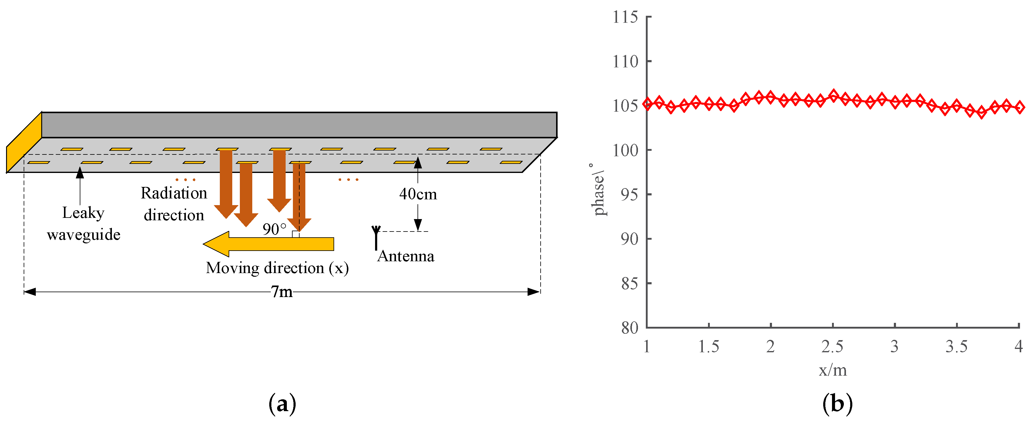
Elimination of Doppler frequency shift: As is mentioned above, the large and time-varying Doppler frequency shift and Doppler spread is one of the distinguishing factors of vactrain’s train-to-ground communicaiton. Fortunately, the Doppler issue may be solved by introducing leaky waveguide. The leaky waveguide is installed on the ceiling of the vacuum tube, producing a cylindrical wave in the broadside direction of leaky waveguide [40]. Thus, the leaky wave always radiates vertically to the operating vactrain. Note that the wave radiated from different hole must have different wavefront when considering the propagation along the waveguide. To deal with this issue, the spacing between the adjacent holes is set to an integer multiple of the wavelength in the design of the waveguide. Thus, the phase of the wave arriving at each hole would be same, and so is the wave-front. Suppose the velocity of the receiving end is v, then the Doppler frequency shift can be presented as
f d = f m cos α = v c f c cos α
where f d represents Doppler frequency shift, f m is the maximum Doppler frequency shift, c is the speed of light, the carrier frequency f c is 3.3 GHz, and α represents the incidence angle of radio wave. As is mentioned above, the angle between the train moving direction and the radiation direction of the leaky wave is always 90 , which means α equals to 90 . According to Equation (1), the Doppler frequency shift can be calculated as f d = 0 , indicating that the Doppler frequency shift can be greatly suppressed or completely eliminated.
(2)
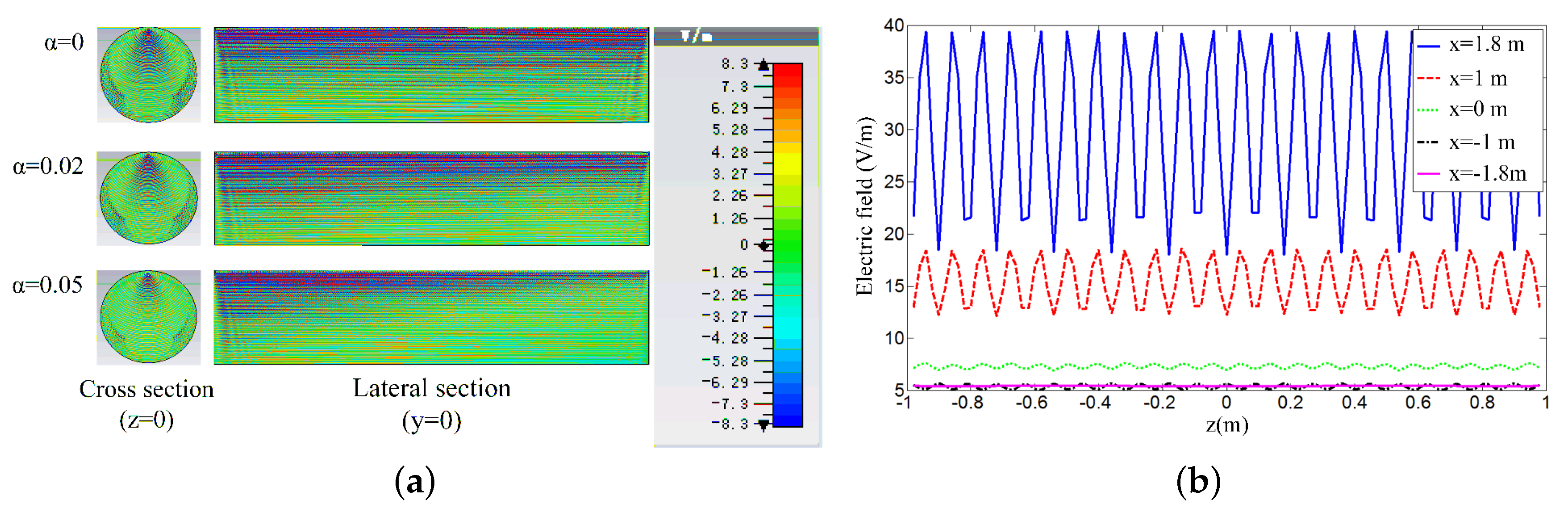
Even field distribution: As the distance between the train receiving antenna and the leakage waveguide is close (~40–50 cm), the signal emitted by leaky waveguide is strong, with the relatively weak multi-path effect of the reflecting or scattering wave. Thus, the field distribution of leaky wave can be uniform at the train receiving antenna.
(3)
Simplification of communication mechanism: As is analyzed above, the Doppler frequency shift could be eliminated or decreased at a quite low level, which indicates that the fast time-variation of the fading channel could be greatly suppressed. In addition, the leaky wave field distribution is also even for vactrain. Thus, the wireless channel between train and the leaky waveguide will be conditioned stationary. This implies that the communication method can be simplified and the complicated communication coding technologies such as OFDM and LDPC can be avoided.

4.3. Simulation

In the following subsections, the simulations of the phase distribution and field distribution of leaky waveguide inside the tube are conducted by the Computer Simulation Technology (CST) studio suite electromagnetic field simulation software. The operation frequency of the leaky waveguide is set to 3.3 GHz, which is a candidate for the 5G communication frequency. Along the top of vacuum tube, it is easy to deploy the leaky waveguide, for example, embedding it into the tube wall. It is known that the magnetic current source arrays have been widely used for leaky waveguide analysis and have the equivalent radiation performance as the leaky waveguide [41]. Further, the magnetic current source arrays can simplify the calculation and analysis of the simulation, and thus improving the efficiency and saving processing time. Thus, in simulation configuration, the leaky waveguide will be replaced with the magnetic current source arrays. Along the direction z of vacuum tube, a 198 magnetic current source array is arranged at the top, and the periodic intervals are set to 90 mm. Thus, a broadside radiation with −1 spatial harmonic can be generated by the magnetic current source arrays. However, the open-stopband, which exits in the actual leaky waveguide, has been eliminated in the simulation to ensure broadside radiation. Thus, in the practical application, a suppression method for the open-stopband is required. In addition, the amplitude of the magnetic current source array gradually attenuates along the z direction, and the decreasing magnitudes can be expressed as e - α z i , where α is the attenuation constant of the leaky waveguide, z i (i = 1,2,3,...,198) is the coordinate of each slot.

4.3.1. Phase Distribution along Tube’s Axial Direction

The simulation of phase distribution along the tube is carried out in this subsection. The overall configuration of leaky waveguide and receiving antenna in the simulation is shown in Figure 2a. The distance between receiving antenna and leaky waveguide is 40 cm. The antenna moves from right to left to collect phase data right below the waveguide. The length of the leaky waveguide is 7 m, and it operates at 3.3 GHz. Due to the field volatility at the ends of the waveguide, the data is collected in the 3 meter long center section. Note that the attenuation constant of the leaky waveguide α is set to zero and the receiving antenna with conventional gain is adopted since the Doppler frequency shift is mainly determined by the phase characteristics of the received signal and independent from the receiving signal level.
The simulation results are shown in Figure 2b. The phase basically floats around 105 with a limited fluctuation range. The flat phase distribution observed above indicates that the Doppler frequency shift could be suppressed effectively. The little variation of the phase is mainly due to the reasons as follows. First, limited by the computing resources, only the simulation for finite-length leaky waveguide could be conducted. However, this will introduce the truncation effect, thus then the edge current will be generated at both ends of the waveguide, resulting in the fluctuations in the field distribution. Second, the field distributions of the leaky wave could be affected by the power attenuation of the propagating electromagnetic wave along the leaky waveguide. Note that the problems caused by finite simulation will no longer exist in practical applications. As for the power attenuation, we could further improve the design of the leaky waveguide to reduce the leakage rate and keep the distribution of leakage field distribution unchanged after attenuation. Thus, compared with the antennas methods in Section 4.1, a more flat phase distribution along the tube’s axial direction would be retained and the Doppler could be further suppressed.

4.3.2. Field Distribution in the Tube

In this subsection, the field distribution of the leaky waveguide inside the vacuum tube will be studied and analyzed. Similar to the above subsection, the leaky waveguide with carrier frequency of 3.3 GHz is adopted. In the simulation configuration, the metal vacuum tube is made of lossy copper material, with length of 18 m and the radius of 2 m.
The simulation results of field distribution inside the vacuum tube with different values of α are shown in Figure 3a [42]. Only the E z component is shown since it is the co-polarized component. It can be seen that the field distribution near the ends of the vacuum pipe has a obvious truncation effect, but that of the area along the longitudinal direction of the vacuum pipe is uniform, indicating leaky waveguide solution is applicable to the vacuum tube transportation. The results show that the field distribution of the leaky waveguide is greatly affected by the values of α in terms of field strength and coverage area. When α increases, which means that the amplitude of the leaky wave propagated in the waveguide will be further attenuates, thus the results show that the fields in the vacuum tube show an attenuation trend along the longitudinal direction. In addition, with the increase of α , the longitudinal range that leaky wave radiated from waveguide can cover is also decreasing. According to the results of the field distributions in the cross section of z = 0 plane, the reflected waves also become weak as the radiated wave reduces rapidly in z direction if α is larger.
The variations of electric fields along the vacuum tube at different heights x when α = 0 is presented in Figure 3b [42]. Note that the leaky waveguide is arranged at x = 2 m. In addition, for the exhibition clarity, the results only present the field distribution of range from z = −1 m to 1 m. It can be seen that the fluctuations of the field distribution are more obvious as x gradually increases. Thus, it can be inferred that the higher harmonics mainly exist in the near region of the waveguide, making the fluctuation more obvious. On the contrary, as the observation height x decreases, the results show that the field magnitude decreases rapidly and the field fluctuation tends to be smoother. This primarily occurs because only the radiating mode (−1 harmonic) can reach the far field region, thus the much smoother distribution can be observed far away from the waveguide. In practical situation, the distance between the leaky waveguide and the user equipments is relatively large, for example, 2 m, thus the signal coverage can be flat for the receiving ends. According to this, it can be inferred that if the structure of the leaky waveguide is reformed to make the −1 harmonic carrying more power, the near field region might also have smooth field distribution, making the which wireless communication for vactrains more flexible and stable.

5. Train-to-Ground Communication Architectures with Leaky Waveguide
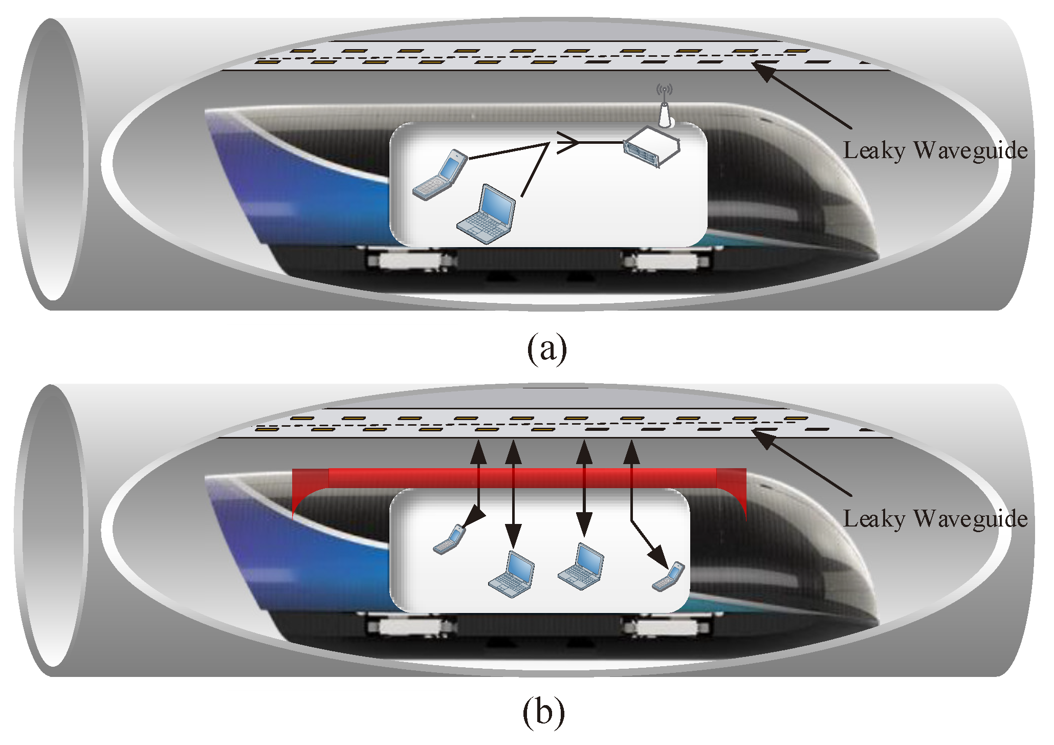
The above simulations indicate that leaky waveguide could not only effectively suppress the high Doppler frequency shift, but also achieve an even field distribution inside the tube. However, the penetration loss caused by the heavy train body still exist. To establish wireless link between train user equipments and leaky waveguide, some solutions will be proposed in this section. These solutions can be classified into two categories, solutions based on Mobile Relays (MRs) and direct coverage solution.

5.1. Mobile Relays

As is shown in Figure 4a, same as that of current HSR [43], the on-board MRs that are usually installed on the train roof can solve the issues of high penetration loss and group handover. These MRs are usually connected to access points (APs) installed inside the train through wired links such as optical fiber. In the uplink, the traffic from all user equipments (UEs) and the on-train equipments are first congregated at the on-board MRs through the APs, then the relay stations forward all the congregated data to the leaky waveguide by the roof antenna. In the downlink, the leaky waveguide transmits all communication data to the MRs, which then deliver the traffic to their intended UEs and train equipments through the APs inside the capsule. As the MRs are connected to the antenna installed outside of the train, it eliminates the penetration loss [43].
The key challenge of this solution for vactrain is the wireless resource allocation for safety-related operational services and non-secure passenger services, which have different transmission requirements in terms of bandwidth and QoS. Thus, the train-to-ground wireless link involved with physical layer needs to be created specifically. Besides, the train relay is responsible for the aggregation and distribution of all UEs’ traffic, which leads to the complex design of MR’s system structure to ensure the transmission performance. This implies that the complexity of the train-to-ground communication system will be increased sharply, resulting in the declines of transmission robustness. In addition, the delay caused by the MR’s forwarding will reduce the stability of the train operational data transmission. As is mentioned above, the communication channels between leaky waveguide and train are stationary, thus there is no need to use MRs with the complex system design. Instead, the solutions related to direct radio coverage for passengers could be available in vactrain scenario.

5.2. On-Train Leaky Lens

As the wireless channel is assumed to be stationary, the direct coverage method could be considered. The direct-link approach assumes a direct connection between leaky waveguide and UEs. In this solution, different radio coverage strategies are applied for safety-related data and passengers’ data separately. On the one hand, the security-related data only needs to be transmitted to the train roof antenna, and then be transmitted to the corresponding on-train equipments through cable links. Thus, the security-related data transmission can be realized by the traditional radio coverage method. On the other hand, the direct wireless link between leaky waveguide and UEs needs to be established for the transmission of passengers’ data. Thus, the on-train leaky wave refractive lens (leaky lens) solution is proposed in this subsection, which could cover wireless signals for passengers directly.
As is shown in Figure 4b, the train roof is opened to install the leaky lens. If the transmitting power is set appropriately, the leaky wave could directly cover the passengers through the leaky lens. When the radio signal passed through the lens, it could be tuned to achieve uniform wireless coverage for passengers.
In the proposed leaky lens system, the leaky waveguide is located at the focus plane of lens, through which the radiated cylindrical leaky wave could be refracted and then tuned to plane wave. As a result, the antenna gain is increased, whereas the antenna sidelobe and backlobe are decreased. Assume that the lens is generally made of dielectric materials, and its refractive index is greater than 1, which implies a retarded phase shift for the signals passed through lens. Base on this, the shape of the lens could be determined using the optical theories, such as Fermat’s principle and Snell law.

5.2.1. Refracted Surface Equation

As is shown in Figure 5, there are two surfaces in the leaky lens: (a) inner-surface and (b) outer-surface. Assume that the leaky lens is a single-surface refracting lens, which means that only one surface could refract the leaky wave. The design for the single-surface refracting lens could be classified into two types in terms of the shape of the refracted surface:
(1)
Hyperboloid lens:
As is shown in Figure 5a, the outer-surface is a plane perpendicular to x-axis, and thus there is no refraction for the wireless wave in this surface. Therefore, the inner-surface is the refracted surface, and its analytic expression could be deduced based on the optical theories. Assume that n = ε r μ r is the refractive index, where ε r and μ r are relative dielectric constant and relative magnetic permeability of the lens, respectively. According to the equal optical path principle, the optical path of the leaky wave from leaky waveguide to the inner-surface can be expressed as
ρ φ = n - 1 f n cos φ
where
ρ φ = f + x 2 + y 2
cos φ = f + x f + x 2 + y 2
Combine Equations (3)–(5), the analytic expression of the inner-surface can be expressed as
n 2 - 1 x 2 + 2 f n - 1 x - y 2 = 0
According to Equation (6), we can see that the inner-surface is a hyperboloid, and the leaky waveguide (radiation sources) needs to be located at the focus or focus plane of the hyperboloid. The hyperboloid lens has the advantages of simple design, easy processing, as well as the effective suppression for sidelobe.
(2)
Ellipsoid lens:
As is shown in Figure 5b, the inner-surface is a sphere with the radius r of ρ 1 , and it is parallel to the equiphase surface of the leaky wave, which means that there is no refraction in this surface. Similar to the hyperboloid lens, the analytic expression of the outer-surface (refracted surface) could be deduced based on the optical theories. According to the equal optical path principle, the optical path of the leaky wave from leaky waveguide to the outer-surface can be expressed as
ρ φ = n - 1 f n - cos φ
where
ρ φ = f + x 2 + y 2
cos φ = f + x f + x 2 + y 2
Combine Equations (7)–(9), the analytic expression of the inner-surface can be expressed as
n 2 - 1 x 2 + 2 n n + 1 f x + n 2 y 2 = 0
According to Equation (10), we can learn that the outer-surface is an ellipsoid, and the leaky waveguide (radiation sources) needs to be located at the focus or focus plane of the ellipsoid. Compared to the hyperboloid lens, the caliber efficiency of ellipsoid lens is higher. Thus, the acceptable angle range of the incident leaky wave is larger, which implies the more even field distribution of the generated wave, the higher radiation efficiency, and then the higher system efficiency. However, there are two surfaces that need to be proceed for ellipsoid lens, which implies a large manufacturing cost.

5.2.2. Lens’ Thickness

To determine the thickness of the above two leaky lens, the ratios of thickness to radiation aperture need to be calculated. Assume that the lens’ thickness is d and the radiation aperture is D. As for hyperboloid lens, consider the point A ( d , D / 2 ) at edge of the lens, as is shown in Figure 5a, and combine this point with Equation (5), thus the ratio of thickness to radiation aperture can be expressed as
d D = - f f D D n + 1 + f f D D 2 1 + n 2 + 1 4 n 2 - 1
Similarly, combine Equation (10) and the point A in Figure 5b, the ratio of thickness to radiation aperture of ellipsoid lens can be expressed as
d D = n n - 1 f D + n 2 f f D D 2 n - 1 2 - n 2 4 n 2 - 1
According to Equations (11) and (12), the thickness of the lens can be calculated if the focal length f and radiation aperture D are determined. Normally, f / D is in the range of 1.0 to 1.6 in the design of leaky lens.

6. Moving Cell Based on C-RAN

The wireless access methods researched or deployed in the current HSR are based on fixed cells or segments [44]. Thus, when the train antenna exceeds the cell boundary of the BS, it needs to disconnect with the old BS and then establish a new connection with the next BS, that is, handover. Considering the leaky waveguide as a solution to provide wireless broadband access for the vactrain, and each segment leaky waveguide corresponds to a BS, with a length of, for example, 100 m. As is mentioned above, when the cell size is reduced and trains’ speed is increased, the handover rate will drastically increase. It is extremely important to keep the handover times as short as possible: the typical handover times of HSR in the order of, for example, 0.1 s to 1s are absolutely intolerable to vactrain. Thus, minimizing the handover times will be the most important challenge. To remedy this situation, the moving cell scheme based on the Centralized, cooperative, cloud radio access network (CRAN) is adopted to reduce the handover time.

6.1. C-RAN Architecture for Vactrain

C-RAN can provide a clean, centralized processing, collaborative radio, and real-time cloud computing infrastructure wireless access architecture by combining the centralized software-defined radio baseband, high-speed optical transmission network, and distributed remote wireless module (RoF, Radio-over-Fibre) [45].
C-RAN is considered as a promising solution to provide high communication services for passengers in vactrain scenario. Figure 6 shows the C-RAN architecture in vactrain scenario [42]. The architecture can be divided into three key components: Remote Radio Units (RAUs), optical transmission network, and the pool of baseband units (BBUs) in a datacenter cloud. All of the BBUs, together with the RAUs, can be connected by the optical network with low-latency.The RAUs, each connected to a segment of waveguide, are only responsible for the radio frequency (RF) transceiving and belongs to none of the fixed BBUs. The base band pools centralize all the digital baseband processing capabilities, which are actually a huge computing resource group.
The key concept of C-RAN is to separate the RAUs from the baseband stations and centralize the latter to a centralized entity, namely, base band pools. Based on this, the design of RAUs could be greatly simplified, thus allowing them to be deployed in large numbers for small cells along the vacuum tube line. The leaky waveguide solutions are adopted to achieve wireless coverage inside the tube, thereby each RAU outside the tube needs to be connected to the corresponding segment of leakage waveguide.

6.2. Moving Cell

In the typical handover process, the train needs to firstly disconnect with the old BS, and then establish a new connection with the next BS. This kind of handoff process will inevitably increase the handoff delay, which can not meet the extremely frequent handoff caused by the ultra-high speed of vactrains. In the concept of moving cell, the handover will not occur due to no cells crossing. The primary reason is that the BS can move simultaneously with the UEs, that is, moving cell. Under this assumption, the communication link between BS and UE can be considered always static regardless of the speed due to no handoffs. At present, based on the above ideas, some physically moving base station schemes have been studied and proposed [46,47]. However, in fact, these physical moving BS solutions can not be put into practice in HSR systems. Lannoo Bart and Colle Didier proposed a moving frequency scheme based on optical handoff, which can reduce the handoff delay to 5 ns to 1 ms [48]. The low handover delay can meet the handover requirements of vactrains, so we adopt the moving frequency scheme in the C-RAN architecture.
The concept of moving frequency can be implemented in C-RAN architecture, which is illustrated in Figure 6. Specifically, the cloud processing center can deploy the next RAU and activates the corresponding leaky waveguide that the train will access through the optical transmission network according to the exact train location information [49]. The ring network can get all the RAUs that are within the range of the cloud processing center connected with the same optical fiber. In addition, using Wavelength Division Multiplexing (WDM), every RAU can be assigned to a specific wavelength. Further, the fixed Optical Add Drop Multiplexer (OADM) is deployed in each RAU, thus the fixed wavelength is terminated in each RAU. The idea is then to put the desired frequency for a certain RAU on the right wavelength, which can be done through the use of some optical switches in combination with a WDM laser. Figure 7 shows a basic optical switching structure, through which the optical switches can be realized. The WDM laser will generate a beam of light that contains the desired wavelengths. The entire beam is then sent to the optical switch, where the right wavelengths are passed to the different RF modulators (each generating the same RF). The mux will multiplex all the modulated wavelengths, and then transmitted through the optical fiber to the right RAU. The RAU equipped with the OADM dropping the corresponding wavelength will transmit the information on RF through leaky waveguide. In other words, the traditional handover process is replaced by the optical switching process, which could be as low as 5 ns to 1 ms. Based on this, the overlapping length of leaky waveguides should be at least 0.3 m with the train speed of 1000 km/h and the optical signal switching process delay of 1 ms. The basic principle of moving frequency with the consideration of single frequency RF signal is shown in Figure 8.
T 1 : The train operates within the leaky wave radiation coverage of R A U i - 1 . In the cloud processing center, the RF signal f i is modulated to the optical signal with the wavelength λ i - 1 . Then, the optical signal will be transferred through the optic fiber to the R A U i - 1 . The R A U i - 1 will transfer the information on RF signal to the leaky waveguide, which is responsible for the train-ground wireless communication.
T 2 : The train reaches the overlapping radiation coverage area of R A U i - 1 and R A U i . The specific position for optical switching can be predicted by fast handoff algorithm [50]. In the switching process, the RF signal f i will be modulated to the optical signal with the wavelength λ i . As is mentioned above, every RAU can be assigned to a specific wavelength. Thus, R A U i , which is assigned to the wavelength of λ i , will be responsible for the RF transceiver function. Further, to ensure that only the RAU covering the train stays active state, the RF function of R A U i - 1 will be disabled.

7. Conclusions and Future Work

The vacuum tube high-speed flight train, whose speed exceeds 1000 km/h, is an novel rail transportation technology. Therefore, a reliable bidirectional communication link between the train and the ground plays a key role in guaranteeing the safe operation of this system. Currently, there is almost no research on train-to-ground communication technology of vactrain. Against this background, this paper summarized several key challenges of train-to-ground wireless communication for the vactrain, and explored the feasibility of current wireless communication technologies for speed over 1000 km/h. In addition, the bandwidth and QoS requirements of vactrain’s train-to-ground communication service are analyzed quantitatively. In terms of wireless access inside the tube, we proposed a leaky waveguide with simple architecture but high performance. The simulation of the leaky waveguide is conducted, and the results show the uniform phase distribution along the horizontal direction of the tube, but also the smooth field distribution at the point far away from the leaky waveguide, which can suppress Doppler frequency shift, indicating that the time-varying frequency-selective fading channel could be approximated as a stationary channel. As the wireless channel can be approximated as a stationary channel, an electromagnetic lens system is proposed to achieve direct wireless coverage for train. Moreover, moving cell scheme based on the C-RAN architecture is adopted to deal with the extremely frequent handoff.
In future work, more research is need to test and simulate the communication performance of the architecture based on leaky waveguide at system level. In the meantime, further studies should investigate the multi-band leaky waveguide and the propagation characteristics of leaky wave inside the full-sealed metal tube. In addition, further research is needed on the near-field convergence technology, of which the basic idea is to form a couple of leaky waveguides into a certain array, and thus converge the radiated leaky wave on the lens through beam-forming. As for the moving cell scheme, the results comparing train speed vs number of switches per second would be considered for a better perspective about the importance of moving cell. In addition, the simulation of moving cell based on C-RAN would be conducted to test the handover performance.

Author Contributions

Conceptualization, C.Q. and L.L.; methodology, L.L.; software, Z.L.; validation, J.Z., C.Q. and T.Z.; formal analysis, C.Q.; investigation, L.L.; resources, B.H.; data curation, T.Z.; writing—Original draft preparation, C.Q.; writing—Review and editing, L.L.; visualization, C.Q. and Z.L.; supervision, L.L.; project administration, L.L.; funding acquisition, L.L. All authors have read and agreed to the published version of the manuscript.

Funding

The research was supported by the Fundamental Research Funds for the Central Universities under grant 2018JBZ102, Beijing Nova Programme Interdisciplinary Cooperation Project(Z191100001119016), and the Center of National Railway Intelligent Transportation System Engineering and Technology (Contract No. RITS2019KF01), China Academy of Railway Sciences.

Acknowledgments

The authors thank the anonymous reviewers for their constructive comments that helped us improve the quality and presentation of this paper.

Conflicts of Interest

The authors declare no conflicts of interest.

References

  1. Jin, M.J.; Huang, L. Development status and trend of ultra high-speed vacuum pipeline transportation technology. Sci. Technol. Chin. 2018, 5, 13–15. [Google Scholar]
  2. Musk, E. Hyperloop Alpha; SpaceX: Hawthorne, CA, USA, 2013. [Google Scholar]
  3. Watch The First Real-World Test Of Hyperloop Technology. Available online: https://digg.com/2016/hyperloop-one-test-video-elon-musk (accessed on 12 May 2016).
  4. Hyperloop Transportation Technologies Begins Construction of Its First Test Track. Available online: https://www.engadget.com/2018/04/12/hyperloop-tt-begins-construction-of-its-first-test-track/ (accessed on 19 April 2018).
  5. Hyperloop Transportation Technologies to Build Hyperloop in Southwest China with Local Partner. Available online: https://technode.com/2018/07/19/elon-musk-to-build-hyperloop-in-southwest-china-with-local-partner/ (accessed on 20 July 2018).
  6. China’s Maglev Trains to Hit 1000 km/h in Three Years, Doc Brown to Finally Get 1985 Squared Away. Available online: https://www.engadget.com/2010/08/04/chinas-maglev-trains-to-hit-1-000kph-in-three-years-doc-brown/ (accessed on 31 August 2017).
  7. Yan, L. Development and application of the Maglev transportation system. IEEE Trans. Appl. Superconduct. 2008, 18, 92–99. [Google Scholar]
  8. Guo, H.; Wu, H.; Zhang, Y. GSM-R network planning for high speed railway. In Proceedings of the IET 3rd International Conference on Wireless, Mobile and Multimedia Networks (ICWMNN 2010), Beijing, China, 26–29 September 2010; pp. 10–13. [Google Scholar]
  9. He, R.; Ai, B.; Wang, G.; Guan, K.; Zhong, Z.; Molisch, A.F.; Briso-Rodriguez, C.; Oestges, C.P. High-speed railway communications: From GSM-R to LTE-R. IEEE Vehic. Technol. Mag. 2016, 11, 49–58. [Google Scholar] [CrossRef]
  10. Xiong, J.; Yu, K. Application of TD-LTE technology in Shuohuang Heavy-haul railway. Railw. Signall. Commun. Eng. 2015, 12, 20–24. [Google Scholar]
  11. Aguado, M.; Jacob, E.; Saiz, P.; Unzilla, J.J.; Higuero, M.V.; Matias, J. Railway signaling systems and new trends in wireless data communication. In Proceedings of the VTC-2005-Fall. 2005 IEEE 62nd Vehicular Technology Conference, Dallas, TX, USA, 28 September 2005; Volume 2, pp. 1333–1336. [Google Scholar]
  12. Zhu, L.; Yu, F.R.; Ning, B.; Tang, T. Cross-layer handoff design in MIMO-enabled WLANs for communication- based train control (CBTC) systems. IEEE J. Sel. Areas Commun. 2012, 30, 719–728. [Google Scholar] [CrossRef]
  13. Smith, K. LTE displays potential in Zhengzhou. Int. Railw. J. 2014, 54, 43. [Google Scholar]
  14. Zhou, M. Analysis on the technical characteristics of wireless communication between vehicles and grounds of Shanghai Maglev line. Urban Mass Transit 2010, 13, 26–29. [Google Scholar]
  15. Kim., J.; Il Kim, G. Distributed antenna system-based millimeter-wave mobile broadband communication system for high speed trains. In Proceedings of the 2013 International Conference on ICT Convergence (ICTC), jeju Island, Korea, 14–16 October 2013; pp. 218–222. [Google Scholar] [CrossRef]
  16. 3GPP TR 38.913. Study on Scenarios and Requirements for Next Generation Access Technologies; ETSI: Sophia Antipolis, France, 2018; Release 14. [Google Scholar]
  17. Zhou, T.; Tao, C.; Salous, S.; Liu, L. Geometry-based multi-link channel modeling for high-speed train communication networks. IEEE Trans. Intell. Transp. Syst. 2019, 1–10. [Google Scholar] [CrossRef]
  18. Masson, É.; Berbineau, M. Broadband Wireless Communications for Railway Applications; Springer International: Berlin/Heidelberg, Germany, 2017. [Google Scholar]
  19. Zhou, T.; Tao, C.; Salous, S.; Liu, L. Measurements and analysis of short-term fading behavior in high-speed railway communication networks. IEEE Trans. Vehic. Technol. 2019, 68, 101–112. [Google Scholar] [CrossRef]
  20. Zhou, T.; Li, H.; Wang, Y.; Liu, L.; Tao, C. Channel modeling for future high-speed railway communication systems: A survey. IEEE Access 2019, 7, 52818–52826. [Google Scholar] [CrossRef]
  21. Guan, K.; Zhong, Z.; Ai, B.; Briso-Rodriguez, C. Propagation mechanism modelling in the near region of circular tunnels. IET Microw. Antennas Propag. 2012, 6, 355–360. [Google Scholar] [CrossRef] [Green Version]
  22. Zhang, L.; Briso, C.; Fernandez, J.R.O.; Alonso, J.I.; Rodríguez, C.; García-Loygorri, J.M.; Guan, K. Delay spread and electromagnetic reverberation in subway tunnels and stations. IEEE Antennas Wirel. Propag. Lett. 2016, 15, 585–588. [Google Scholar] [CrossRef]
  23. Guan, K.; Zhong, Z.; Ai, B.; Briso-Rodriguez, C. Propagation mechanism analysis before the break point inside tunnels. In Proceedings of the 2011 IEEE Vehicular Technology Conference (VTC Fall), San Francisco, TX, USA, 5–8 September 2011; pp. 1–5. [Google Scholar]
  24. Zhou, T.; Tao, C.; Salous, S.; Liu, L. Joint channel characteristics in high-speed railway multi-link propagation scenarios: Measurement, analysis, and modeling. IEEE Trans. Intell. Transp. Syst. 2019, 20, 2367–2377. [Google Scholar] [CrossRef]
  25. Liu, Y.; Wang, C.X.; Lopez, C.; Ge, X. 3D non-stationary wideband circular tunnel channel models for high-speed train wireless communication systems. Sci. Chin. Inf. Sci. 2017, 60, 082304. [Google Scholar] [CrossRef]
  26. Liu, Y.; Ghazal, A.; Wang, C.X.; Ge, X.H.; Yang, Y.; Zhang, Y.P. Channel measurements and models for high-speed train wireless communication systems in tunnel scenarios: a survey. Sci. Chin. Inf. Sci. 2017, 60, 101301. [Google Scholar] [CrossRef] [Green Version]
  27. Zhou, T.; Tao, C.; Liu, L. LTE-assisted multi-link MIMO channel characterization for high-speed train communication systems. IEEE Trans. Vehic. Technol. 2019, 68, 2044–2051. [Google Scholar] [CrossRef]
  28. Ghazal, A.; Wang, C.X.; Ai, B.; Yuan, D.; Haas, H. A nonstationary wideband MIMO channel model for high-mobility intelligent transportation systems. IEEE Trans. Intell. Transp. Syst. 2014, 16, 885–897. [Google Scholar] [CrossRef] [Green Version]
  29. Bian, J.; Sun, J.; Wang, C.; Feng, R.; Huang, J.; Yang, Y.; Zhang, M. A WINNER + based 3-D non-stationary wideband MIMO channel model. IEEE Trans. Wirel. Commun. 2018, 17, 1755–1767. [Google Scholar] [CrossRef]
  30. Wang, C.; Ghazal, A.; Ai, B.; Liu, Y.; Fan, P. Channel measurements and models for high-speed train communication systems: A survey. IEEE Commun. Surv. Tutor. 2016, 18, 974–987. [Google Scholar] [CrossRef] [Green Version]
  31. Zhu, X.; Chen, S.; Hu, H.; Su, X.; Shi, Y. TDD-based mobile communication solutions for high-speed railway scenarios. IEEE Wirel. Commun. 2013, 20, 22–29. [Google Scholar] [CrossRef]
  32. IEEE Standard 802.11. Wireless LAN Medium Access Control (MAC) and Physical Layer (PHY) Specifications; IEEE: New York, NY, USA, 2012. [Google Scholar]
  33. Zhou, T.; Tao, C.; Salous, S.; Liu, L. Measurements and analysis of angular characteristics and spatial correlation for high-speed railway channels. IEEE Trans. Intell. Trans. Syst. 2018, 19, 357–367. [Google Scholar] [CrossRef] [Green Version]
  34. Zhao, H.; Zhu, L.; Jiang, H.; Tang, T. Design and performance tests in an integrated TD-LTE based train ground communication system. In Proceedings of the 17th International IEEE Conference on Intelligent Transportation Systems (ITSC), Quindao, China, 8–11 October 2014; pp. 747–750. [Google Scholar]
  35. Zhong, Z.D.; He, R.S.; Guan, K.; Ai, B.; Zhu, G.; Lei, L.; Wang, F.G.; Ding, J.W.; Xiong, L.; Wu, H. Dedicated Mobile Communications for High-Speed Railway; Springer: Berlin/Heidelberg, Germany, 2017. [Google Scholar]
  36. Martino, L.; Read, J.; Elvira, V.; Louzada, F. Cooperative parallel particle filters for online model selection and applications to urban mobility. Digit. Signal Proc. 2017, 60, 172–185. [Google Scholar] [CrossRef] [Green Version]
  37. Watanatada, T.; Ben-Akiva, M. Forecasting urban travel demand for quick policy analysis with disaggregate choice models: A Monte Carlo simulation approach. Trans. Res. Part A General 1979, 13, 241–248. [Google Scholar] [CrossRef]
  38. Chopin, N.; Jacob, P.E.; Papaspiliopoulos, O. SMC2: An efficient algorithm for sequential analysis of state space models. J. R. Stat. Soc. Ser. B Stat. Method. 2013, 75, 397–426. [Google Scholar] [CrossRef] [Green Version]
  39. Elvira, V.; Martino, L.; Bugallo, M.F.; Djuric, P.M. Elucidating the auxiliary particle filter via multiple importance sampling [Lecture Notes]. IEEE Signal Proc. Mag. 2019, 36, 145–152. [Google Scholar] [CrossRef]
  40. Jackson, D.R.; Caloz, C.; Itoh, T. Leaky-Wave Antennas. Proc. IEEE 2012, 100, 2194–2206. [Google Scholar] [CrossRef]
  41. Wei, B.; Li, Z.; Liu, L.; Wang, J. Field distribution characteristics of leaky-wave system in the vacuum tube for high-speed rail. In Proceedings of the 2018 12th International Symposium on Antennas, Propagation and EM Theory (ISAPE), Hangzhou, China, 3–7 December 2018; pp. 1–3. [Google Scholar]
  42. Qiu, C.; Liu, L.; Liu, Y.; Li, Z.; Zhang, J.; Zhou, T. Key technologies of broadband wireless communication for vacuum tube high-speed flying train. In Proceedings of the 2019 IEEE 89th Vehicular Technology Conference (VTC2019-Spring), Kuala Lumpur, Malasya, 28 April–1 May 2019; pp. 1–5. [Google Scholar]
  43. Wu, J.; Fan, P. A survey on high mobility wireless communications: Challenges, opportunities and solutions. IEEE Access 2016, 4, 450–476. [Google Scholar] [CrossRef]
  44. Zhou, T.; Tao, C.; Salous, S.; Liu, L.; Tan, Z. Channel sounding for high-speed railway communication systems. IEEE Commun. Mag. 2015, 53, 70–77. [Google Scholar] [CrossRef] [Green Version]
  45. I, C.; Huang, J.; Duan, R.; Cui, C.; Jiang, J.X.; Li, L. Recent progress on C-RAN centralization and cloudification. Access IEEE 2014, 2, 1030–1039. [Google Scholar] [CrossRef]
  46. Gavrilovich, C.D. Broadband communication on the highways of tomorrow. Commun. Mag. IEEE 2001, 39, 146–154. [Google Scholar]
  47. Nakayama, Y.; Maruta, K.; Tsutsumi, T.; Sezaki, K. Optically backhauled moving network for local trains: Architecture and scheduling. IEEE Access 2018, 6, 31023–31036. [Google Scholar] [CrossRef]
  48. Lannoo, B.; Colle, D.; Pickavet, M.; Demeester, P. Radio-over-fiber-based solution to provide broadband internet access to train passengers [Topics in Optical Communications]. Commun. Mag. IEEE 2007, 45, 56–62. [Google Scholar] [CrossRef]
  49. Liu, P.; Liu, L.; Tao, C.; Sun, R. The study of C-RAN application on broadband wireless access for high-speed railway. In International Conference on Wireless Communications; IET: Stevenage, UK, 2014; pp. 226–230. [Google Scholar]
  50. Lee, S.; Kim, N.; Yun, H.; Kang, M. Optical switching based on position-tracking algorithm to realize “Moving Cells“ in a RoF network. In Proceedings of the 2008 10th International Conference on Advanced Communication Technology, Gangwon-Do, Korea, 17–20 February 2008; Volume 3, pp. 2170–2173. [Google Scholar]
Figure 1. Simulation of the antennas methods: (a) Configuration of antennas methods. (b) Doppler spectrum of antenna methods.
Applsci 10 01379 g001
Figure 2. Phase distribution of the leaky waveguide method: (a) Configuration of leaky waveguide and receiving antenna. (b) The phase distribution of different measuring point.
Applsci 10 01379 g002
Figure 3. Field distribution of the leaky waveguide method: (a) Field distribution ( E z ) with different α (Np/m). (b) The variations of field distribution ( E z component) with different heights x when α = 0 [42].
Applsci 10 01379 g003
Figure 4. Wireless access solutions for vactrain: (a) Mobile relay station and (b) Leaky lens [42].
Applsci 10 01379 g004
Figure 5. Two types of leaky lens: (a) Hyperboloid lens and (b) ellipsoid lens.
Applsci 10 01379 g005
Figure 6. C-RAN system architecture for vactrain [42].
Applsci 10 01379 g006
Figure 7. Basic architecture in the cloud processing center to implement moving cell [42].
Applsci 10 01379 g007
Figure 8. Basic principle to implement moving frequency concept.
Applsci 10 01379 g008
Table 1. Applied wireless technologies in railway systems.
TechnologyDatarate (DL/UL)Working FrequencySupporting SpeedMaturity
GSM-R172 Kbps885∼889 MHz(UL)
930∼934 MHz(DL)
<500 km/hEnd of Life 2025
LTE-R50 Mbps/10 Mbps450/800/1400 MHz<500 km/hEmerging
WLAN12 Mbps/12 Mbps2.4/5 GHz<100 km/hWidely adopted
LTE-M50 Mbps/10 Mbps1.785∼1.805 GHz<500 km/hEmerging
28G mmW2000 Mbps27 GHz<400 km/hEmerging
38G mmW
(Maglev)
8 Mbps/4 Mbps37.1∼38.5 GHz<500 km/hMature
Table 2. Train-to-ground wireless communication performance requirements.
Data TypeEnd-to-end Transmission Delay/msData Rate / KbpsBit Error Rate
Urban RailHSRMglevVactrainUrban RailHSRMglevVactrainUrban RailHSRMglevVactrain
ULDLULDLULDLULDL
OCS100504040200/train200/train200/train1000/train 10 - 6 10 - 6 10 - 6 10 - 6
TCS51 10 - 6 10 - 6 10 - 6 10 - 6
OVC100100404032/ channel32/channel32/channel32/channel 10 - 2 10 - 3 10 - 5 10 - 5
TOSM300150300300100-200-200-1000- 10 - 3 10 - 6 10 - 3 10 - 3
Video3001503003006000-4000-4000-18000- 10 - 3 10 - 3 10 - 3 10 - 3
PIS3003003003001008000100100010010001008000 10 - 6 10 - 3 10 - 6 10 - 6
Table 3. Quality of Service (QoS) criteria for classification of multimedia applications.
Error TolerantError Intolerant
Interactive
(delay ≪ 1 s)
Conversational voice and videoInteractive games
Responsive
(delay ≈ 2 s)
Voice/video messagingWeb browsing
Timely
(delay ≈ 10 s)
Audio and video streamingMessaging, downloads
Non-critical
(delay ≫ 10 s)
FaxBackground

