Article

Biomechanical Effect of Various Tibial Bearing Materials in Uni-Compartmental Knee Arthroplasty Using Finite Element Analysis

1
Department of Orthopaedic Surgery, Yonsei University College of Medicine, Severance Hospital, Seoul 03722, Korea
2
Department of Mechanical Engineering, Yonsei University, 50 Yonsei-ro, Seodaemun-gu, Seoul 03722, Korea
3
Department of Orthopaedic Surgery, Joint Reconstruction Center, Yonsei Sarang Hospital, 10 Hyoryeong-ro, Seocho-gu, Seoul 06698, Korea
*
Author to whom correspondence should be addressed.
These authors contributed equally to this work.
Appl. Sci. 2020, 10(18), 6487; https://doi.org/10.3390/app10186487
Submission received: 9 June 2020 / Revised: 14 August 2020 / Accepted: 15 September 2020 / Published: 17 September 2020

Abstract

:
This paper aimed to evaluate the biomechanical effects of tibial bearing materials, from ultra-high-molecular-weight polyethylene (UHMWPE) to poly-ether-ether-ketone (PEEK) and carbon-fiber-reinforced poly-ether-ether-ketone (CFR-PEEK). The studies were conducted based on a validated finite element model. The geometry of the intact knee model was developed from computed tomography and magnetic resonance imaging of the left knee joint of a 37-year-old healthy male volunteer. Three different loading conditions, related to the loads applied in the experimental research, were applied to this study for model predictions and validation. The contact stress in the other compartments was under normal walking conditions. Also, stresses on five regions of the tibia bone were analyzed under normal walking conditions. The lowest contact stress between the lateral meniscus and tibial cartilage was achieved in the order of the use of CFR-PEEK, PEEK, and UHMWPE tibial bearings. Moreover, CFR-PEEK and PEEK tibial bearings indicated lower and greater stresses on cortical and trabecular bones, respectively, compared to the UHMWPE tibial bearing. These results show that CFR-PEEK can be used as a tibial bearing material as an alternative to UHMWPE, and such a change in the material may be a good method for reducing potential anteromedial pain.

1. Introduction

Uni-compartmental knee arthroplasty (UKA) has recently become a popular procedure owing to its excellent treatment of anteromedial osteoarthritis (OA), particularly for focal defect treatment in younger patients and in those with early localized OA of the knee [1,2,3].
Although several clinical studies have reported that UKA can mimic the motion of an intact knee [4,5], and some authors have shown outstanding results over 10 years of follow-up with up-to-date designs [1,6], failures with this procedure have been reported [7,8]. The clinical outcomes of UKA have shown four main postoperative problems: malpositioning of the prosthetic parts, tibial bearing wear, OA progression in the remaining compartments, and localized tibia bone stress [7,8,9,10]. Because of the recently strict selection of patients and advanced surgical techniques, the long-term survival rate post-UKA has been significantly enhanced [3].
In both types, fixed and mobile bearings, the wear of tibial bearings made from ultra-high-molecular-weight polyethylene (UHMWPE) is an important issue in the long-term performance of UKA [8,11]. The perceived requirement to lessen contact stress in a UKA design has led to the introduction of highly conforming and low-contact-stress designs. Although these implant geometries have indeed lessened contact stress on the articulating surface, the increase of conformity has tended to lead to an over-constraint in the joint, with a risk of mechanical failure due to secondary stresses occurring within the bearings [12].
Developments during the last decades have presented significant changes in manufacturing and sterilization methods, as well as material technologies, enhancing the mechanical properties, oxidative stability, and wear of UHMWPE [13,14]. However, such an apparent trade-off between each of these factors with increasing cross-linkage is associated with a decrease in fatigue resistance [13,14]. There have been several investigations of substitute materials for UHMWPE, including poly-ether-ether-ketone (PEEK) and carbon-fiber-reinforced PEEK (CFR-PEEK).
Brockett et al. reported that highly conforming designs, such as total hip replacement and conforming UKA using CFR-PEEK, have shown low wear in in vitro knee wear simulations [15]. However, they recently stated that the wear rates of both PEEK and CFR-PEEK tibial bearings were nearly twice that of UHMWPE tibial bearings under comparable conditions for total knee arthroplasty (TKA) [16]. S C Scholes and A Unsworth reported that UKA with a CFR-PEEK tibial bearing provided lower volumetric wear rates than conventional metal-on-UHMWPE prostheses when tested under equivalent conditions [17]. Further research is required to substantiate whether CFR-PEEK is an appropriate substitute material for UHMWPE in terms of wear performance. However, as far as we know, there has been an information deficiency on tibia bone stress, which is an important criterion for aseptic loosening and anteromedial pain, when using PEEK and CFR-PEEK tibial bearing materials. Besides this, there has been no study that has evaluated contact stress on the other compartments with regard to the different materials.
As previously mentioned, part malpositioning and wear problems can be overcome through proper surgical technique and a change in material, respectively. However, it is impractical to experimentally evaluate progressive OA on the other compartments and tibia bone stress problems based on a change in material. In addition, tibia bone stress is an important criterion for aseptic loosening and anteromedial pain [18,19,20]. The biomechanical effects of a change in tibial bearing material on the contact stress in the lateral meniscus and articular cartilage, and on stress on the tibia bone, can be evaluated in a practical manner using finite element (FE) analysis. Our prior study showed the biomechanical effect on varus/valgus conditions relating to UHMWPE and CFR-PEEK tibial bearing material in UKA. However, there has been no study of PEEK tibial bearing material in UKA [21].
This paper aimed to evaluate alternative polymers to replace UHMWPE as tibial bearing materials in UKA. The biomechanical effects of UHMWPE, PEEK, and CFR-PEEK as the tibial bearing material were compared. The contact stresses in the lateral meniscus and articular cartilage, and the stress on the tibia bone, were evaluated under gait cycle conditions. We hypothesized that CFR-PEEK, the stiffness of which is closest to that of bone, would show the best biomechanical effect.

2. Materials and Methods

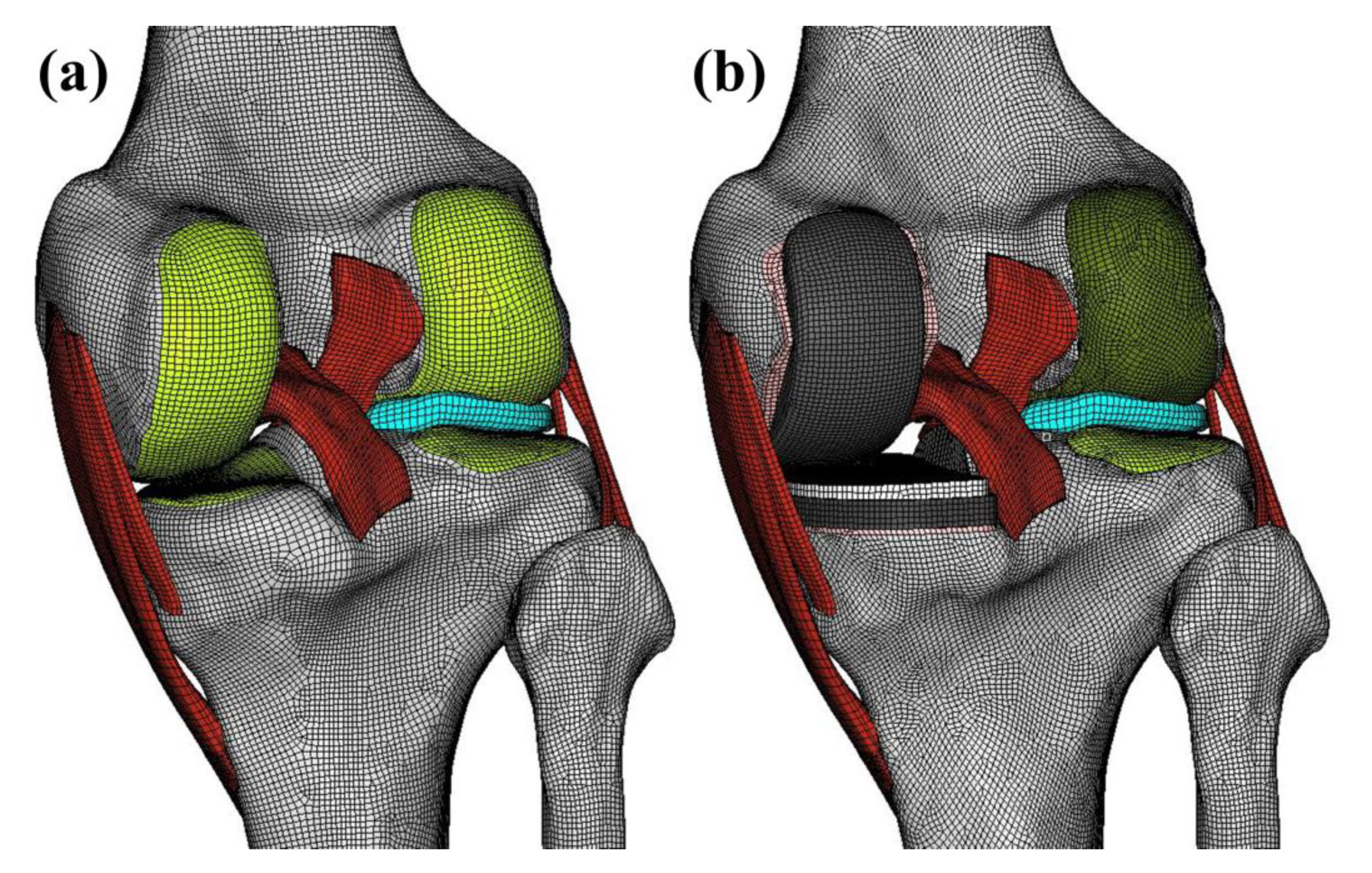
2.1. Computational Model of the Intact Knee Joint

This study was performed using an entirely validated FE model of the knee joint, developed in our prior studies [22,23,24,25] from computed tomography (CT) and magnetic resonance imaging (MRI) of the left knee joint of a 37-year-old healthy male volunteer [26]. The manual segmentation had an accuracy of 0.1 mm. The combination process for the reconstructed CT and MRI models was via positional alignment of each model using commercial software, Rapidform (version 2006; 3D Systems Korea, Seoul, Korea). The image data were then imported into Mimic 17.0 image processing software (Materialise Ltd., Leuven, Belgium) to obtain the geometry for the three-dimensional (3D) model generation of all structures. The initial graphics exchange specification (IGES) files exported from Mimic were imported into Unigraphics NX software (version 7.0; Siemens PLM Software, Torrance, CA, USA) to generate solid models for each femur, tibia, fibula, patella, and soft-tissue segment. The solid models were then imported into Hypermesh software (version 8.0; Altair Engineering, Troy, MI, USA) to create an FE mesh. The FE mesh analysis was conducted through the use of ABAQUS (version 6.11; Simulia, Providence, RI, USA) (Figure 1a).
All bones except the tibia were assumed to be rigid, whereas the tibia was considered to be transversely isotropic in this model because it is stiffer than soft tissue, with minimal effect on the current research [27]. The constitutive laws for the cortical and trabecular bones of the tibia were assumed [28,29]. The cortical bone was regarded as transversely isotropic. Its mechanical properties were applied as follows: E1 = E2 = 11.5 GPa, E3 = 17 GPa, ν12 = 0.51, and ν23 = ν13 = 0.31. We took the third axis to be parallel to the anatomical axis of each bone. The trabecular bone was regarded as a linear isotropic material. The material properties were applied as follows: E = 2.13 GPa and ν = 0.3 [28,29]. The articular cartilage was assumed to be a linear elastic and isotropic material because a simple compressive and time-independent load was applied to the knee joint. Its mechanical properties were a modulus of 15 MPa and a Poisson ratio of 0.47 [30]. The menisci were assumed to be of a transversely isotropic, linearly elastic, homogeneous material. Their moduli were 120 MPa in the circumferential direction and 20 MPa in the axial and radial directions. The Poisson ratios of the menisci were 0.2 in both the circumferential and radial directions and 0.3 in the axial direction [31]. To represent the meniscal attachments, each meniscal horn was bonded to the bone through the use of linear spring elements (SPRINGA element type) with a total stiffness of 2000 N/mm [32]. In addition, the major ligaments were modeled through the use of nonlinear and tension-only spring elements [33,34]. The interfaces between the bones and cartilage were modeled as fully bonded. The contacts between the femoral cartilage and meniscus, the meniscus and tibial cartilage, and the femoral cartilage and tibial cartilage were applied to both the medial and lateral sides, resulting in six contact pairs [22]. Contact was defined using a penalty-based method with a weight factor. As a result, contact forces were defined as a function of the penetration distance of the master into the slave surface.

2.2. Computational Model of UKA

A fixed-bearing UKA (Zimmer, Inc., Warsaw, IN, USA) was virtually implanted in the medial compartment of the normal knee model (Figure 1b). The normal bone models were imported and adequately located, trimmed, and meshed with rigid elements through the use of surgical techniques [35].
Size 6 and 5 devices were used for the femoral and tibial parts, respectively, based on the anatomical geometries of the femur and tibia. The devices were then aligned using the mechanical axis and placed at the medial edge of the tibia. The tibial baseplate, neutrally aligned, was defined as having a square (0°) inclination in the coronal plane with a 5° posterior slope. The axis of rotation was defined as a line parallel to the lateral edge of the tibial part passing through the center of the femoral part peg. A neutral femoral part distal cut perpendicular to the mechanical axis of the femur was reproduced, parallel to the tibial cut.
In relation to the implanted model, a 1 mm gap for bone cement was applied between the implant part and bone. The femoral and tibial parts, bone cement, and tibial bearing (UHMWPE, PEEK, and CFR-PEEK) were assumed to be linear elastic isotropic materials [18,36,37,38,39,40]. A tibial bearing thickness of 8 mm was applied on all three different models.
In terms of modulus of elasticity and Poisson’s ratio, the material properties of each part were as shown in Table 1 [18,36,37,38,39,40].
According to the range reported in the literature, the friction coefficients between the articulating surfaces were assumed to be 0.07, 0.06, and 0.04 for UHMWPE, PEEK, and CFR-PEEK, respectively [37,41,42]

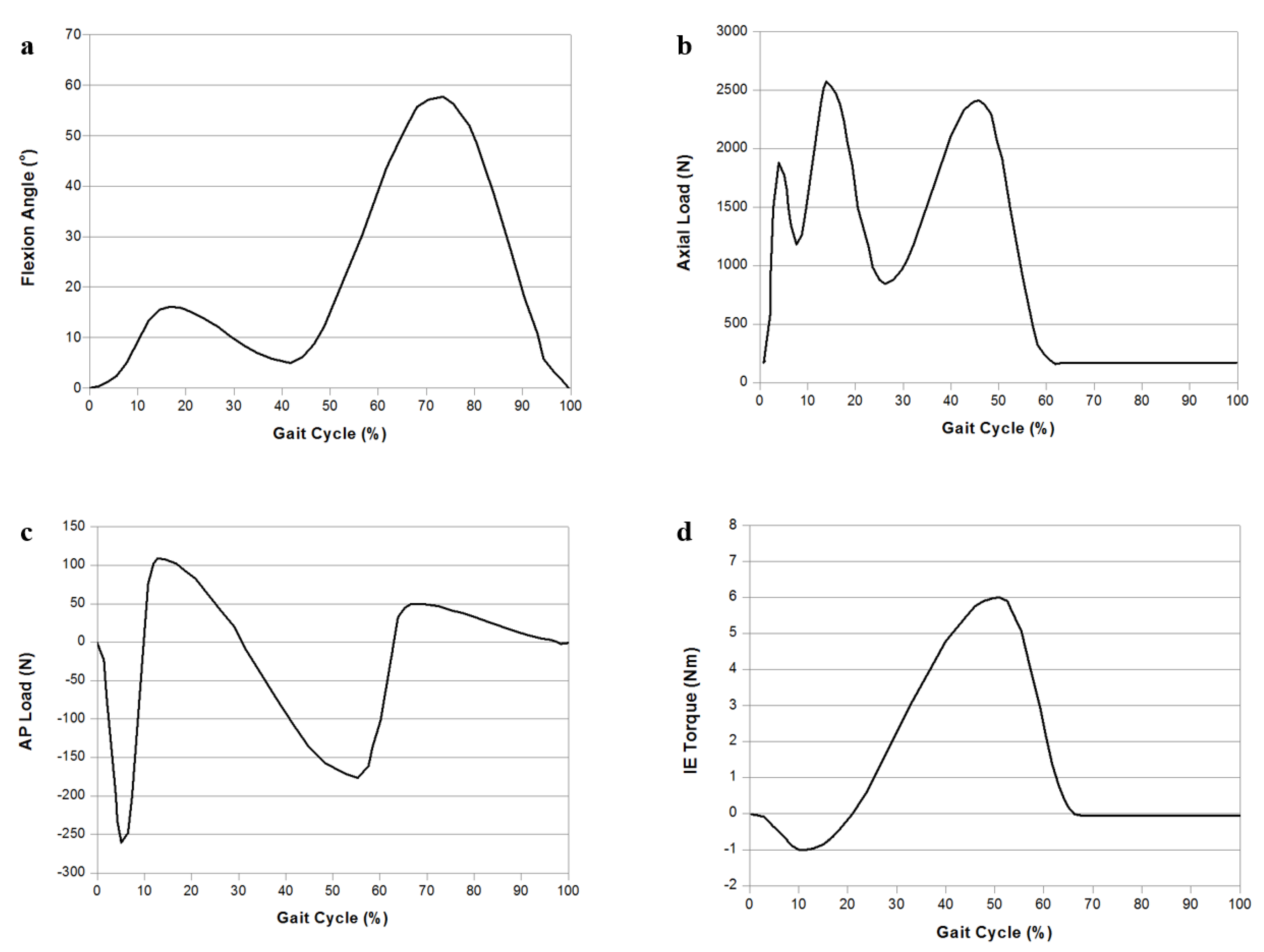
2.3. Loading and Boundary Conditions

For model predictions and validation for clinically relevant loading scenarios, three different loading conditions related to the loads applied in the experimental research were applied to this FE study. Identically simulated loading protocols were used in the experiment for validation of the model. Under the first loading condition, 150 N was applied to the tibia with 30° and 90° flexion in the knee joint to evaluate the anterior and posterior tibial translations [23]. Under the second loading condition, an axial load of 1150 N was applied on the FE model to obtain the contact stresses and to compare them with those reported in a published FE study on the knee joint [27]. Under the third loading condition, UKA model validation was conducted with four flexion angles (0°, 30°, 60°, and 90°) using passive flexion simulation. Furthermore, anterior and posterior drawer loads of 130 N were applied separately to the tibia at the center of the knee, equivalent to the conditions in experimental research [43]. As a fourth loading condition, gait cycle loading was applied to compare the biomechanical effects of the three different tibial bearing materials (Figure 2) [44]. A computational analysis was performed using force controls of the anterior–posterior force in regard to the compressive load applied to the hip [45,46]. A proportional–integral–derivative controller was integrated into the computational model to allow for the control of the quadriceps in a manner equivalent to that in the experiment [47]. Internal–external and varus–valgus torques were applied to the tibia [45,46]. The contact stresses on the lateral meniscus and tibial cartilage were analyzed in the other compartments, as well as tibial bone stress, influencing residual pain. Five regions of interest (ROIs) were defined on the proximal tibia (Figure 3). ROIs 1 and 4 were defined at the resection corner between the sagittal and transverse tibia bone cuts. The other three ROIs were located on the trabecular bone surface beneath the tibial baseplate, with ROIs 2 and 3 being medial and lateral to the keel slot, respectively. ROI 5 was defined to investigate the cause of residual pain and was positioned on the proximal anteromedial surface of cortical bone for all models.

3. Results

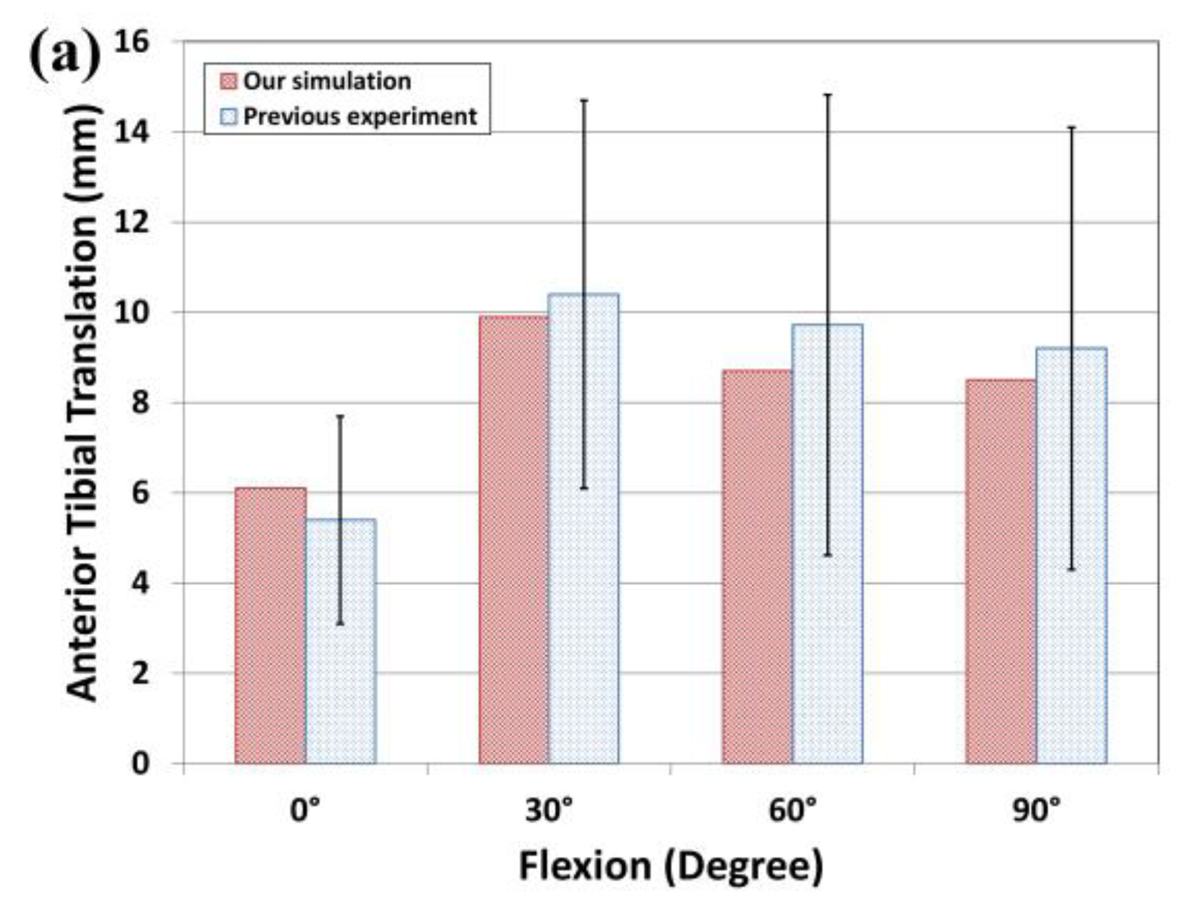
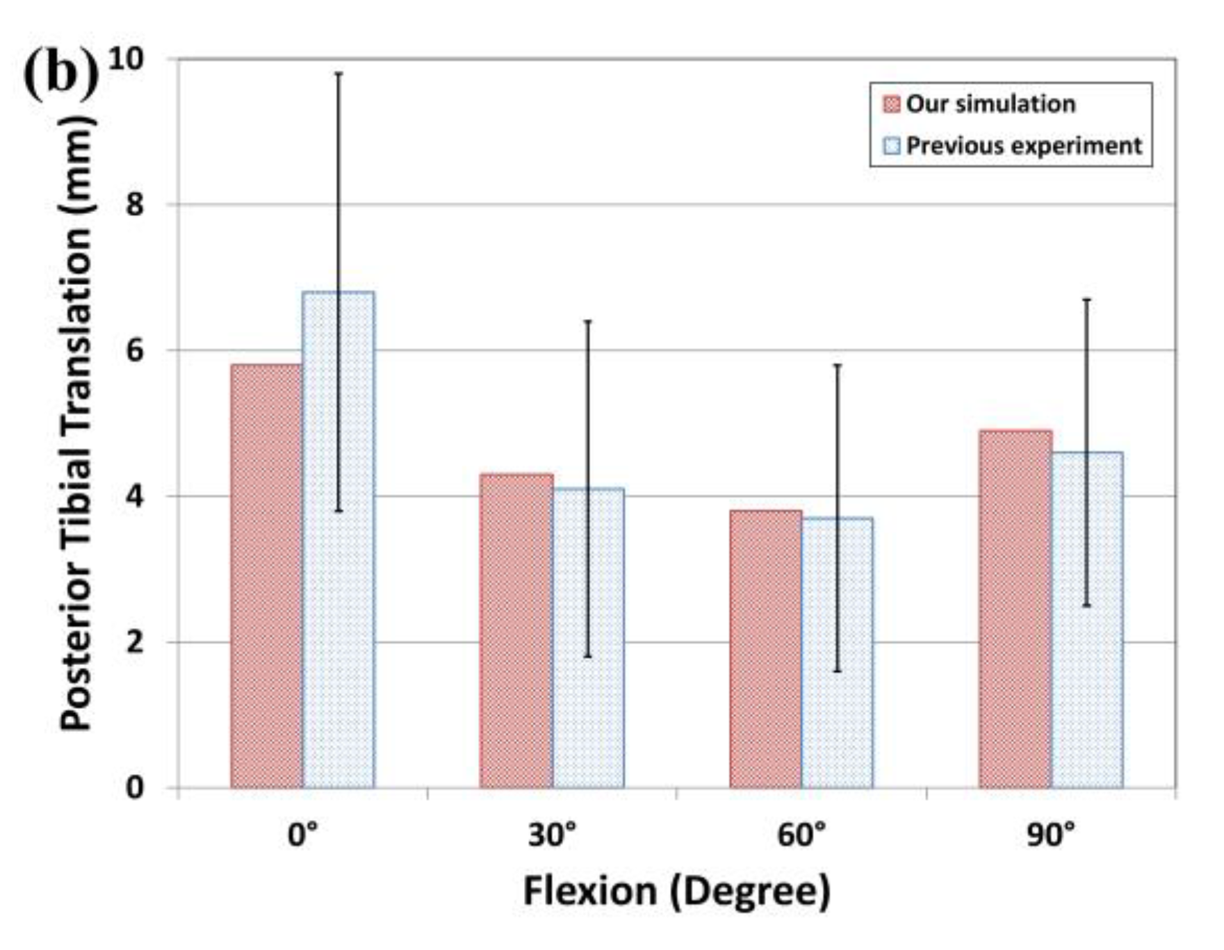
3.1. Intact and UKA Model Validation

The FE model was subjected to evaluations based on experimental data available in the literature. The intact model validation was conducted in a previous study [22,23] and is briefly introduced herein. Mesh convergence was defined as the point at which cartilage pressures were within 95% of the pressure of the next two smaller mesh sizes. This criterion was met by a mesh size of 2.0 mm. If the differences between FE model simulations and experimental data were lower than two standard deviations (SDs) from the mean of the experimental data, the FE model was considered to be validated. This was explained with an in vivo laxity test for the subject identical to the FE model. The laxity test was applied to the anterior–posterior drawer under 30° and 90° of flexion with a series of stress radiographs. Its results were compared with the results from the experiment on the FE model’s subject to validate the intact FE model. Under the loading condition with 30° flexion, the anterior tibial translation was measured as 2.83 mm in the experiment and 2.54 mm in the FE model, and the posterior tibial translation was measured as 2.12 mm in the experiment and 2.18 mm in the FE model for validation [23]. A good agreement was thus shown between the experiment results and the FE model. In addition, the results were also compared with previous FE results for validation. Under an axial load of 1150 N, average contact pressures of 3.1 and 1.53 MPa were evaluated on the medial and lateral meniscus, respectively. Both contact pressures were within 4% of the equivalent pressures of 2.9 and 1.45 MPa reported by Pena et al. [27]. These minor differences might have been due to variations in the geometries, such as the thickness of the cartilage and meniscus, between different studies. However, on an overall basis, the high consistency between the results of the validation and reference substantiated the FE model’s ability to produce reasonable results [27]. The UKA model validation was performed through the use of anterior and posterior translations of tibial compartments in the anterior and posterior drawer tests at 134 N for 6.1, 9.9, 8.7, and 8.5 mm; and 5.8, 4.3, 3.8, and 4.9 mm at 0°, 30°, 60°, and 90° knee flexion in the UKA model, respectively (Figure 4). These findings from the simulation indicate good agreement with prior experimental data within the ranges of values under the anterior and posterior drawer loads [43].

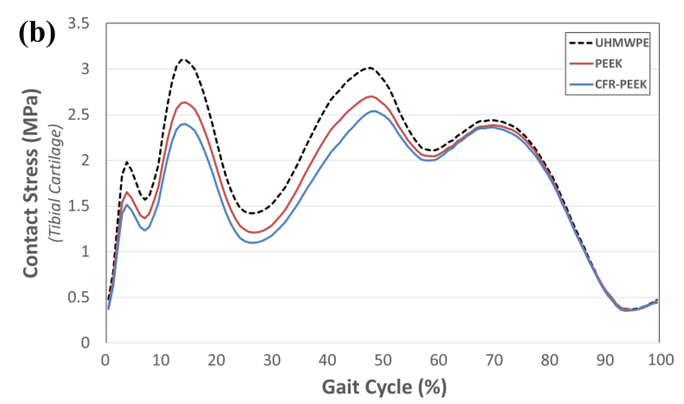
3.2. Comparison of Contact Stress on Other Compartments in Regard to Change in Tibial Bearing Material

Figure 5 indicates the contact stress in the lateral meniscus and tibial cartilage with respect to tibial bearing materials UHMWPE, PEEK, and CFR-PEEK during the gait cycle. The lateral meniscus and tibial cartilage were influenced during the stance phase regardless of the tibial bearing material used. The maximum contact stress was found in the lateral meniscus and tibial cartilage, in which the axial force showed important loading at 13% and 47% of the gait cycle. The PEEK and CFR-PEEK tibial bearings showed 49% and 79% lower contact stress than the UHMWPE tibial bearing in the lateral meniscus. In addition, the PEEK and CFR-PEEK tibial bearings showed 47% and 70% lower contact stress than the UHMWPE tibial bearing in the tibial cartilage.

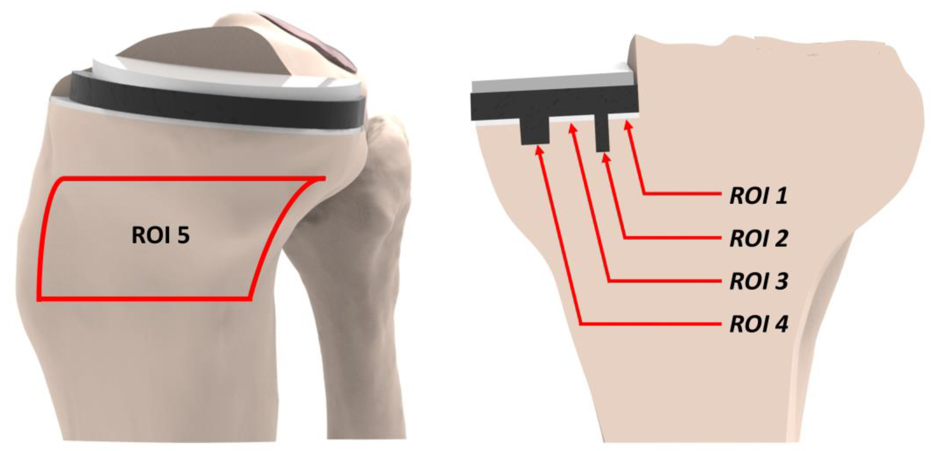
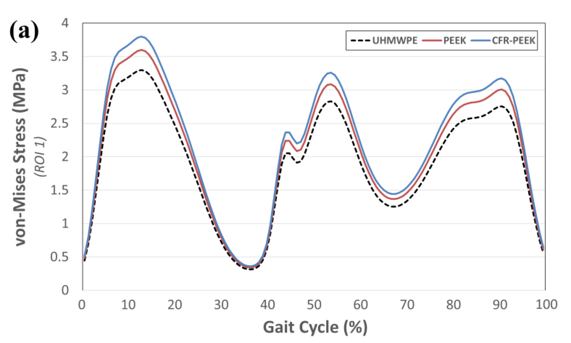
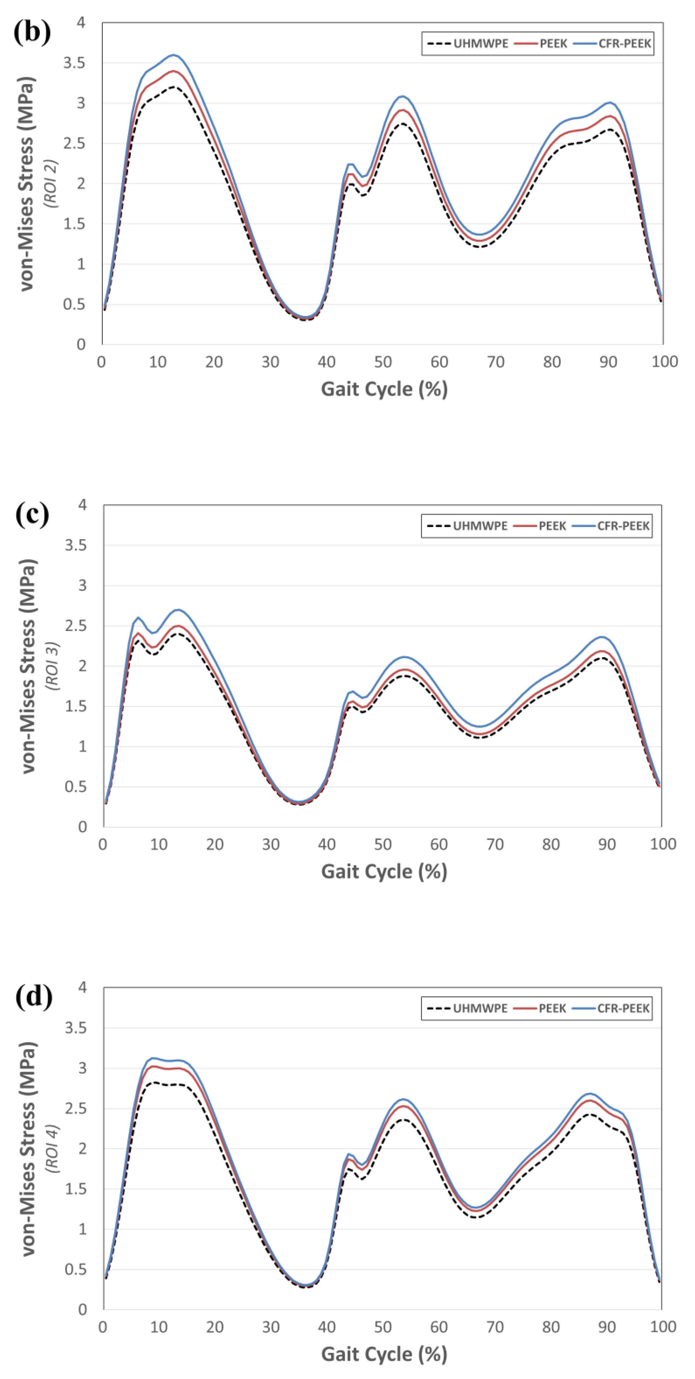
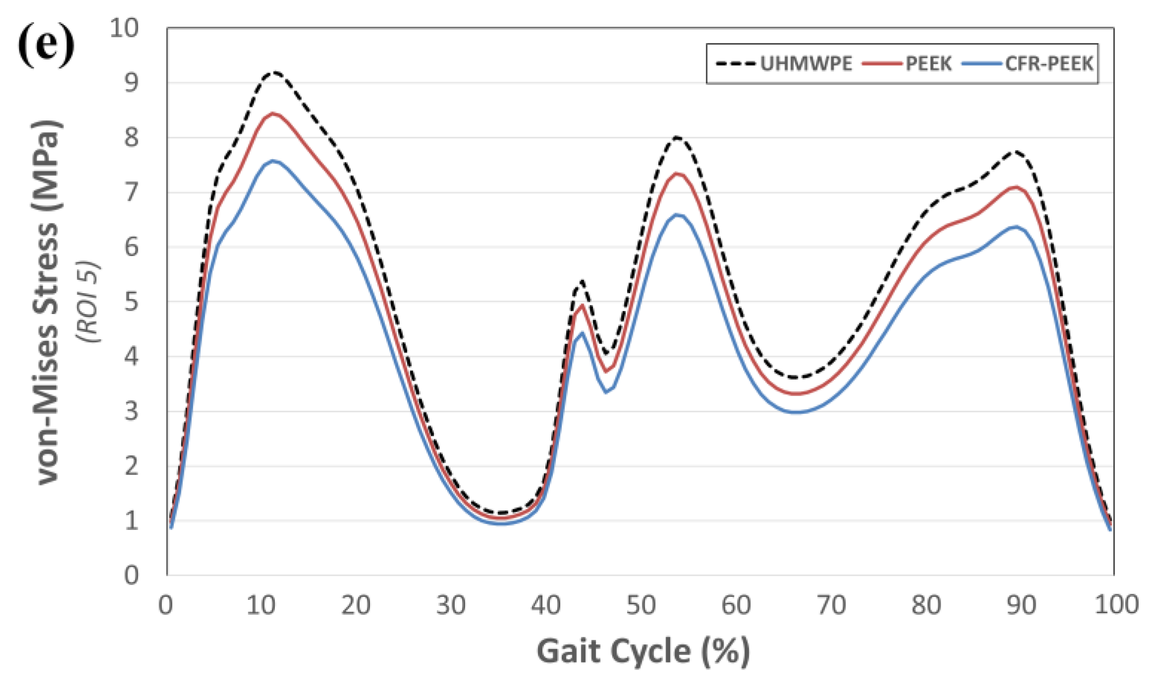
3.3. Comparison of von Mises Stress in Tibial Bone ROIs in Regard to Change in Tibial Bearing Material

Figure 6 indicates the von Mises stress in the tibial bone ROIs with respect to the tibial bearing materials UHMWPE, PEEK, and CFR-PEEK during the gait cycle. ROIs 1 and 2 showed the greatest stress in the trabecular bone regions, ROIs 1–4, in all three models, and it was found to occur during the stance phase. However, unlike the contact stress, there was a difference in stress in regard to the different tibial bearing materials during the gait cycle. In the trabecular bone region, PEEK and CFR-PEEK showed greater stress, but they showed lower stress than the UHMWPE model in the cortical bone region, ROI 5.

4. Discussion

In this study, the most significant finding was that other compartments’ contact stress and tibial bone stress, which are the most serious postoperative problems of UKA, are improved when using CFR-PEEK instead of UHMWPE.
Recently, there have been many developments and improvements in orthopedic implants, which require significant attention and are surgically used to treat joint diseases and traumatic injuries, along with their associated complications [48]. For example, knee joint OA is very common in people over 60 years of age. For severe cases of knee OA, TKA is the standard type of care, relieving the patient’s pain and allowing them to return to their ordinary daily activities [49,50]. In spite of such improvement, the lifetime of the prosthesis is fundamentally limited, with infection, instability, aseptic loosening, periprosthetic fractures, and mechanical wear being the reasons for TKA revision [51,52]. Consequently, many patients need to undergo TKA revision within 10 years after their primary surgery. Consequently, novel implants with advanced materials are being presented and evaluated to improve implant survival rates and reduce the burden of associated TKA revision [53].
PEEK and CFR-PEEK are popular as implantable orthopedic biomaterials used in spinal surgery, usually in the form of intervertebral cages [48,54]. There has recently been growing interest in improvements in the affinity of PEEK and CFR-PEEK for bone ongrowth and ingrowth applications. CFR-PEEK is a biocompatible material and is sufficiently durable for long-term implantation. Its elastic modulus is very similar to that of bone, and it can endure prolonged fatigue strain [48].
In a previous study, PEEK and CFR-PEEK were investigated as substitute bearing materials for metallic and ceramic interfaces [54]. Research on simple pin-on-plate configurations, with PEEK or CFR-PEEK pins articulating against cobalt–chromium, zirconia-toughened alumina ceramic, and polymeric plates, has generally proved that CFR-PEEK has equivalent or better wear performance when compared to conventional polyethylene materials [55,56]. Although PEEK does not appear to provide equivalent wear performance against hard bearings, pin-on-plate studies have shown that it may be a suitable material for articulation with another polymer [57]. As mentioned above, the currently used UHMWPE may cause worse problems for UKA than for TKA. Because UKA is also used as a surgical treatment for younger patients, the functionality of the tibial bearing is more important. In addition, as far as we know, there has been no research regarding the biomechanical effects in other compartments or with the tibial bone when using CFR-PEEK as a tibial bearing.
We found that the lowest contact stress occurred on the lateral meniscus and tibial cartilage when using CFR-PEEK. In addition, the greatest contact stress was found during the stance phase, during which an axial force occurred. This trend was equivalent to those found in previous research [26,58]. Because the contact stress is mainly affected by compressive loading, during the swing phase, where there is no compressive load, no difference was observed in the contact stress with the change in material. In addition, the difference in contact stress for the different materials was greater in the lateral meniscus than in the articular cartilage, which is due to the anatomical difference between the lateral meniscus and tibial cartilage. A meniscus is a bumper for an articular surface, equivalent to a bearing; therefore, there is a greater difference in the lateral meniscus with respect to the change in material.
Aseptic loosening of the prosthetic parts, particularly in the tibia, is one of the major failure modes of UKA [4]. Therefore, aseptic loosening of the tibial part has been attributed to abnormally low or high stress/strain of trabecular bone, both of which induce substantiating bone absorption. In addition, aseptic loosening is also caused by UHMWPE wear-debris-induced osteolysis.
In the present research, we mostly evaluated the trabecular bone stress at the implant–bone interface and observed certain findings. We revealed that stress on the tibial bone ROIs 1–4 with CFR-PEEK and PEEK was greater than that with UHMWPE. Although the tibial part is made of titanium alloy, the CFR-PEEK tibial bearing is equivalent to bone in terms of its mechanical properties and may lessen the aseptic loosening in the tibial part with less of a stress-shielding effect. Some patients have problems with anteromedial pain over the proximal tibia in daily life, early after implantation, which almost always decreases during the first year. However, in a small number of patients, it persists and may even worsen. It is therefore important to understand why such pain occurs, why it spontaneously decreases in most cases, and why it remains and worsens in other cases. The elastic modulus of cortical bone, being even larger than that of trabecular bone, always leads to most of the load being transferred by the tibial baseplate. The abnormally high stress/strain on the proximal medial area of cortical bone has been used to explain the persistent pain post-UKA. Therefore, the level of stress was analyzed in ROI 5 with respect to the tibial bearing material applied. Our results may be explained by the change in bearing material being a good remedy for anteromedial pain, that is, the mechanical properties of CFR-PEEK are more similar to those of bone in comparison to UHMWPE. The stress increases in the cortical bone and the stress decreases in the trabecular bone around the tibial baseplate may lead to pain, inducing loosening of the tibial baseplate [59,60,61,62]. Therefore, CFR-PEEK showed the potential to decrease anteromedial pain and loosening of the tibial baseplate when compared to PEEK and UHMWPE by way of its decreased stress on cortical bone and increased stress on trabecular bone. In addition, unlike contact stress occurring in other compartments, stress on the bone is influenced during the gait cycle. Stress is an important factor not only in terms of axial force but also in translation and rotation, unlike contact stress.
We recently showed that a CFR-PEEK pedicle screw rod is a good device with regard to the degeneration in the adjacent segment in the lumbar spine as compared to titanium [39]. In other words, it is very beneficial for the mechanical properties of the implant to be equivalent to those of bone.
It is important to emphasize some of the strengths derived from this research. First, unlike prior research on UKA, the FE model applied in this research included the femur and related soft tissues, as well as the tibia [18,19,36]. Second, unlike the conventional biomechanical model of UKA, this research included the application of the gait cycle loading condition, as opposed to the application of a vertical static loading condition [18,19,20,36,40,59]. Third, the current research validated the intact model, and the UKA model was also validated by anterior tibial translation (ATT) and posterior tibial translation (PTT) comparisons with experiments from a prior study.
Nevertheless, some limitations should be noted. First, the lateral compartment was regarded as an elastic material. In addition, no effects of anisotropy and viscoelasticity were considered. Second, the UKA designs and anatomy were regarded and virtually created and implanted from just one subject and one prosthetic product. Third, the UKA had been fully bonded and there was no consideration given in this paper to micro-motion that may occur between the PE bearing and the tibial part. Lastly, we only considered change in the tibial bearing material. In future studies, the relationship between tibial baseplates will be studied.

5. Conclusions

In conclusion, this study established that FE analysis can provide local mechanical data not available from in vivo or other types of experiments, allowing us to evaluate the mechanical factors affecting the biomechanical environment when using different tibial bearing materials. The contact stress was evaluated to investigate progressive degenerative OA on other compartments, and the von Mises stress was evaluated to investigate aseptic loosening and anteromedial pain in tibia bone. We found that the CFR-PEEK tibial bearing showed the lowest amount of contact stress in the lateral meniscus and tibial cartilage. Also, the lowest stress showing no anteromedial pain was shown in ROI 5. Therefore, CFR-PEEK may be a good alternative material to UHMWPE, showing a positive biomechanical effect post-UKA.

Author Contributions

Conceptualization, Y.-G.K. and K.-T.K.; methodology, K.-T.K.; software, H.-T.H.; validation, Y.H.K. and K.-T.K.; formal analysis, K.-T.K.; investigation, Y.H.K.; resources, Y.-G.K.; data curation, H.-T.H.; writing—original draft preparation, Y.H.K. and H.-T.H.; writing—review and editing, Y.-G.K. and K.-T.K.; visualization, H.-T.H.; supervision, K.-T.K.; project administration, K.-T.K.; All authors have read and agreed to the published version of the manuscript.

Funding

This research received no external funding.

Conflicts of Interest

The authors declare no conflict of interest.

References

  1. Berger, R.A.; Meneghini, R.M.; Jacobs, J.J.; Sheinkop, M.B.; Della Valle, C.J.; Rosenberg, A.G.; Galante, J.O. Results of unicompartmental knee arthroplasty at a minimum of ten years of follow-up. J. Bone Joint Surg. Am. Vol. 2005, 87, 999–1006. [Google Scholar] [CrossRef]
  2. Riddle, D.L.; Jiranek, W.A.; McGlynn, F.J. Yearly incidence of unicompartmental knee arthroplasty in the United States. J. Arthroplast. 2008, 23, 408–412. [Google Scholar] [CrossRef] [PubMed]
  3. Pandit, H.; Jenkins, C.; Gill, H.S.; Barker, K.; Dodd, C.A.; Murray, D.W. Minimally invasive Oxford phase 3 unicompartmental knee replacement: Results of 1000 cases. J. Bone Joint Surg. Br. Vol. 2011, 93, 198–204. [Google Scholar] [CrossRef] [PubMed]
  4. Berger, R.A.; Nedeff, D.D.; Barden, R.M.; Sheinkop, M.M.; Jacobs, J.J.; Rosenberg, A.G.; Galante, J.O. Unicompartmental knee arthroplasty. Clinical experience at 6- to 10-year followup. Clin. Orthop. Relat. Res. 1999, 367, 50–60. [Google Scholar]
  5. Suggs, J.F.; Li, G.; Park, S.E.; Sultan, P.G.; Rubash, H.E.; Freiberg, A.A. Knee biomechanics after UKA and its relation to the ACL—A robotic investigation. J. Orthop. Res. 2006, 24, 588–594. [Google Scholar] [CrossRef]
  6. Murray, D.; Goodfellow, J.; O’Connor, J. The Oxford medial unicompartmental arthroplasty: A ten-year survival study. J. Bone Joint Surg. Br. Vol. 1998, 80, 983–989. [Google Scholar] [CrossRef]
  7. Aleto, T.J.; Berend, M.E.; Ritter, M.A.; Faris, P.M.; Meneghini, R.M. Early failure of unicompartmental knee arthroplasty leading to revision. J. Arthroplast. 2008, 23, 159–163. [Google Scholar] [CrossRef]
  8. Parratte, S.; Pauly, V.; Aubaniac, J.M.; Argenson, J.N. No long-term difference between fixed and mobile medial unicompartmental arthroplasty. Clin. Orthop. Relat. Res. 2012, 470, 61–68. [Google Scholar] [CrossRef] [Green Version]
  9. Stenström, A.; Lewold, S. Multicenter study of unicompartmental knee revision: PCA, Marmor, and St Georg compared in 3777 cases of arthrosis. Acta Orthop. Scand. 1992, 63, 256–259. [Google Scholar]
  10. Palmer, S.; Morrison, P.; Ross, A. Early catastrophic tibial component wear after unicompartmental knee arthroplasty. Clin. Orthop. Relat. Res. 1998, 350, 143–148. [Google Scholar] [CrossRef]
  11. Price, A.; Short, A.; Kellett, C.; Beard, D.; Gill, H.; Pandit, H.; Dodd, C.; Murray, D. Ten-year in vivo wear measurement of a fully congruent mobile bearing unicompartmental knee arthroplasty. J. Bone Joint Surg. Br. Vol. 2005, 87, 1493–1497. [Google Scholar] [CrossRef] [PubMed] [Green Version]
  12. Sathasivam, S.; Walker, P.S. The conflicting requirements of laxity and conformity in total knee replacement. J. Biomech. 1999, 32, 239–247. [Google Scholar] [CrossRef]
  13. Pruitt, L.A.; Ansari, F.; Kury, M.; Mehdizah, A.; Patten, E.W.; Huddlestein, J.; Mickelson, D.; Chang, J.; Hubert, K.; Ries, M.D. Clinical trade-offs in cross-linked ultrahigh-molecular-weight polyethylene used in total joint arthroplasty. J. Biomed. Mater. Res. B Appl. Biomater. 2013, 101, 476–484. [Google Scholar] [CrossRef] [PubMed]
  14. Atwood, S.A.; Van Citters, D.W.; Patten, E.W.; Furmanski, J.; Ries, M.D.; Pruitt, L.A. Tradeoffs amongst fatigue, wear, and oxidation resistance of cross-linked ultra-high molecular weight polyethylene. J. Mech. Behav. Biomed. Mater. 2011, 4, 1033–1045. [Google Scholar] [CrossRef] [PubMed]
  15. Brockett, C.L.; Carbone, S.; Fisher, J.; Jennings, L.M. PEEK and CFR PEEK as an alternative to UHMWPE in total knee replacement. In Proceedings of the ORS Annual Meeting, Las Vegas, NV, USA, 24–28 March 2015. [Google Scholar]
  16. Brockett, C.L.; Carbone, S.; Fisher, J.; Jennings, L.M. PEEK and CFR-PEEK as alternative bearing materials to UHMWPE in a fixed bearing total knee replacement: An experimental wear study. Wear 2017, 374–375, 86–91. [Google Scholar] [CrossRef]
  17. Scholes, S.C.; Unsworth, A. Pitch-based carbon-fibre-reinforced poly (ether-ether-ketone) OPTIMA assessed as a bearing material in a mobile bearing unicondylar knee joint. Proc. Inst. Mech. Eng. H 2009, 223, 13–25. [Google Scholar] [CrossRef]
  18. Pegg, E.C.; Walter, J.; Mellon, S.J.; Pandit, H.G.; Murray, D.W.; D’Lima, D.D.; Fregly, B.J.; Gill, H.S. Evaluation of factors affecting tibial bone strain after unicompartmental knee replacement. J. Orthop. Res. 2013, 31, 821–828. [Google Scholar] [CrossRef] [PubMed]
  19. Iesaka, K.; Tsumura, H.; Sonoda, H.; Sawatari, T.; Takasita, M.; Torisu, T. The effects of tibial component inclination on bone stress after unicompartmental knee arthroplasty. J. Biomech. 2002, 35, 969–974. [Google Scholar] [CrossRef]
  20. Zhu, G.D.; Guo, W.S.; Zhang, Q.D.; Liu, Z.H.; Cheng, L.M. Finite element analysis of mobile-bearing unicompartmental knee arthroplasty: The influence of tibial component coronal alignment. Chin. Med. J. 2015, 128, 2873–2878. [Google Scholar] [CrossRef]
  21. Koh, Y.-G.; Hong, H.-T.; Kang, K.-T. Biomechanical Effect of UHMWPE and CFR-PEEK insert on tibial component in unicompartmental knee replacement in different varus and valgus alignments. Materials 2019, 12, 3345. [Google Scholar] [CrossRef] [Green Version]
  22. Kim, Y.S.; Kang, K.-T.; Son, J.; Kwon, O.-R.; Choi, Y.-J.; Jo, S.-B.; Choi, Y.W.; Koh, Y.-G. Graft extrusion related to the position of allograft in lateral meniscal allograft transplantation: Biomechanical comparison between parapatellar and transpatellar approaches using finite element analysis. Arthrosc. J. Arthrosc. Relat. Surg. 2015, 31, 2380–2391.e2. [Google Scholar] [CrossRef] [PubMed]
  23. Kang, K.T.; Kim, S.H.; Son, J.; Lee, Y.H.; Chun, H.J. Computational model-based probabilistic analysis of in vivo material properties for ligament stiffness using the laxity test and computed tomography. J. Mater. Sci. Mater. Med. 2016, 27, 183. [Google Scholar] [CrossRef] [PubMed]
  24. Kwon, O.R.; Kang, K.T.; Son, J.; Suh, D.S.; Baek, C.; Koh, Y.G. Importance of joint line preservation in unicompartmental knee arthroplasty: Finite element analysis. J. Orthop. Res. 2017, 35, 347–352. [Google Scholar] [CrossRef] [PubMed]
  25. Kang, K.T.; Kim, S.H.; Son, J.; Lee, Y.H.; Kim, S.; Chun, H.J. Probabilistic evaluation of the material properties of the in vivo subject-specific articular surface using a computational model. J. Biomed. Mater. Res. B Appl. Biomater. 2017, 105, 1390–1400. [Google Scholar] [CrossRef]
  26. Kang, K.T.; Son, J.; Suh, D.S.; Kwon, S.K.; Kwon, O.R.; Koh, Y.G. Patient-specific medial unicompartmental knee arthroplasty has a greater protective effect on articular cartilage in the lateral compartment: A finite element analysis. Bone Joint Res. 2018, 7, 20–27. [Google Scholar] [CrossRef]
  27. Pena, E.; Calvo, B.; Martinez, M.A.; Palanca, D.; Doblare, M. Why lateral meniscectomy is more dangerous than medial meniscectomy. A finite element study. J. Orthop. Res. 2006, 24, 1001–1010. [Google Scholar] [CrossRef]
  28. Kayabasi, O.; Ekici, B. The effects of static, dynamic and fatigue behavior on three-dimensional shape optimization of hip prosthesis by finite element method. Mater. Des. 2007, 28, 2269–2277. [Google Scholar] [CrossRef]
  29. Hoffler, C.; Moore, K.; Kozloff, K.; Zysset, P.; Goldstein, S.A. Age, gender, and bone lamellae elastic moduli. J. Orthop. Res. 2000, 18, 432–437. [Google Scholar] [CrossRef]
  30. Shepherd, D.E.; Seedhom, B.B. The ‘instantaneous’ compressive modulus of human articular cartilage in joints of the lower limb. Rheumatology (Oxford) 1999, 38, 124–132. [Google Scholar] [CrossRef] [Green Version]
  31. Donahue, T.L.H.; Hull, M.; Rashid, M.M.; Jacobs, C.R. How the stiffness of meniscal attachments and meniscal material properties affect tibio-femoral contact pressure computed using a validated finite element model of the human knee joint. J. Biomech. 2003, 36, 19–34. [Google Scholar] [CrossRef]
  32. Guess, T.M.; Thiagarajan, G.; Kia, M.; Mishra, M. A subject specific multibody model of the knee with menisci. Med. Eng. Phys. 2010, 32, 505–515. [Google Scholar] [CrossRef]
  33. Takeda, Y.; Xerogeanes, J.W.; Livesay, G.A.; Fu, F.H.; Woo, S.L. Biomechanical function of the human anterior cruciate ligament. Arthrosc. J. Arthrosc. Relat. Surg. 1994, 10, 140–147. [Google Scholar] [CrossRef]
  34. Blankevoort, L.; Huiskes, R. Validation of a three-dimensional model of the knee. J. Biomech. 1996, 29, 955–961. [Google Scholar] [CrossRef] [Green Version]
  35. Zimmer, I. Zimmer® Unicompartmental High Flex Knee: Intramedullary, Spacer Block Option and Extramedullary Minimally Invasive Surgical Techniques; Zimmer, Inc.: Warsaw, IN, USA, 2010. [Google Scholar]
  36. Inoue, S.; Akagi, M.; Asada, S.; Mori, S.; Zaima, H.; Hashida, M. The valgus inclination of the tibial component increases the risk of medial tibial condylar fractures in unicompartmental knee arthroplasty. J. Arthroplast. 2016, 31, 2025–2030. [Google Scholar] [CrossRef]
  37. Godest, A.C.; Beaugonin, M.; Haug, E.; Taylor, M.; Gregson, P.J. Simulation of a knee joint replacement during a gait cycle using explicit finite element analysis. J. Biomech. 2002, 35, 267–275. [Google Scholar] [CrossRef]
  38. Innocenti, B.; Truyens, E.; Labey, L.; Wong, P.; Victor, J.; Bellemans, J. Can medio-lateral baseplate position and load sharing induce asymptomatic local bone resorption of the proximal tibia? A finite relement study. J. Orthop. Surg. Res. 2009, 4, 26. [Google Scholar] [CrossRef] [Green Version]
  39. Kang, K.-T.; Koh, Y.-G.; Son, J.; Yeom, J.S.; Park, J.-H.; Kim, H.-J. Biomechanical evaluation of pedicle screw fixation system in spinal adjacent levels using polyetheretherketone, carbon-fiber-reinforced polyetheretherketone, and traditional titanium as rod materials. Compos. Part B Eng. 2017, 130, 248–256. [Google Scholar] [CrossRef]
  40. Innocenti, B.; Pianigiani, S.; Ramundo, G.; Thienpont, E. Biomechanical effects of different varus and valgus alignments in medial unicompartmental knee arthroplasty. J. Arthroplast. 2016, 31, 2685–2691. [Google Scholar] [CrossRef]
  41. Knight, L.A.; Pal, S.; Coleman, J.C.; Bronson, F.; Haider, H.; Levine, D.L.; Taylor, M.; Rullkoetter, P.J. Comparison of long-term numerical and experimental total knee replacement wear during simulated gait loading. J. Biomech. 2007, 40, 1550–1558. [Google Scholar] [CrossRef]
  42. Greco, A.C.; Erck, R.; Ajayi, O.; Fenske, G. Effect of reinforcement morphology on high-speed sliding friction and wear of PEEK polymers. Wear 2011, 271, 2222–2229. [Google Scholar] [CrossRef]
  43. Suggs, J.F.; Li, G.; Park, S.E.; Steffensmeier, S.; Rubash, H.E.; Freiberg, A.A. Function of the anterior cruciate ligament after unicompartmental knee arthroplasty: An in vitro robotic study. J. Arthroplast. 2004, 19, 224–229. [Google Scholar] [CrossRef] [PubMed]
  44. International Organization for Standardization. ISO 14243-1: Implants for Surgery—Wear of Total Knee-Joint Prostheses—Part 1: Loading and Displacement Parameters for Wear-Testing Machines with Load Control and Corresponding Environmental Conditions for Test; ISO: Geneva, Switzerland, 2002. [Google Scholar]
  45. Halloran, J.P.; Clary, C.W.; Maletsky, L.P.; Taylor, M.; Petrella, A.J.; Rullkoetter, P.J. Verification of predicted knee replacement kinematics during simulated gait in the Kansas knee simulator. J. Biomech. Eng. 2010, 132, 081010. [Google Scholar] [CrossRef]
  46. Kutzner, I.; Heinlein, B.; Graichen, F.; Bender, A.; Rohlmann, A.; Halder, A.; Beier, A.; Bergmann, G. Loading of the knee joint during activities of daily living measured in vivo in five subjects. J. Biomech. 2010, 43, 2164–2173. [Google Scholar] [CrossRef]
  47. Kang, K.T.; Koh, Y.G.; Son, J.; Kwon, O.R.; Baek, C.; Jung, S.H.; Park, K.K. Measuring the effect of femoral malrotation on knee joint biomechanics for total knee arthroplasty using computational simulation. Bone Joint Res. 2016, 5, 552–559. [Google Scholar] [CrossRef]
  48. Li, C.S.; Vannabouathong, C.; Sprague, S.; Bhandari, M. The use of carbon-fiber-reinforced (CFR) PEEK material in orthopedic implants: A systematic review. Clin. Med. Insights Arthritis Musculoskelet. Disord. 2015, 8. [Google Scholar] [CrossRef] [PubMed]
  49. Escobar, A.; Quintana, J.; Bilbao, A.; Arostegui, I.; Lafuente, I.; Vidaurreta, I. Responsiveness and clinically important differences for the WOMAC and SF-36 after total knee replacement. Osteoarthr. Cartil. 2007, 15, 273–280. [Google Scholar] [CrossRef] [Green Version]
  50. Brander, V.A.; Stulberg, S.D.; Adams, A.D.; Harden, R.N.; Bruehl, S.; Stanos, S.P.; Houle, T. Ranawat Award Paper: Predicting total knee replacement pain: A prospective, observational study. Clin. Orthop. Relat. Res. 2003, 416, 27–36. [Google Scholar] [CrossRef] [PubMed]
  51. Tay, K.S.; Lo, N.N.; Yeo, S.J.; Chia, S.-L.; Tay, D.; Chin, P.L. Revision total knee arthroplasty: Causes and outcomes. Ann. Acad. Med. Singapore 2013, 42, 178–183. [Google Scholar]
  52. Sharkey, P.F.; Hozack, W.J.; Rothman, R.H.; Shastri, S.; Jacoby, S.M. Why are total knee arthroplasties failing today? Clin. Orthop. Relat. Res. 2002, 404, 7–13. [Google Scholar] [CrossRef]
  53. Kurtz, S.M.; Devine, J.N. PEEK biomaterials in trauma, orthopedic, and spinal implants. Biomaterials 2007, 28, 4845–4869. [Google Scholar] [CrossRef] [Green Version]
  54. Kurtz, S.M. Editorial Comment: Advances in PEEK Technology. Clin. Orthop. Relat. Res. 2016, 474, 2362–2363. [Google Scholar] [CrossRef] [PubMed] [Green Version]
  55. Brockett, C.L.; Carbone, S.; Abdelgaied, A.; Fisher, J.; Jennings, L.M. Influence of contact pressure, cross-shear and counterface material on the wear of PEEK and CFR-PEEK for orthopaedic applications. J. Mech. Behav. Biomed. Mater. 2016, 63, 10–16. [Google Scholar] [CrossRef] [PubMed] [Green Version]
  56. Scholes, S.C.; Unsworth, A. Wear studies on the likely performance of CFR-PEEK/CoCrMo for use as artificial joint bearing materials. J. Mater. Sci. Mater. Med. 2009, 20, 163–170. [Google Scholar] [CrossRef] [PubMed]
  57. Scholes, S.; Unsworth, A.J.W. The wear performance of PEEK-OPTIMA based self-mating couples. Wear 2010, 268, 380–387. [Google Scholar] [CrossRef]
  58. Kwon, O.R.; Kang, K.T.; Son, J.; Kwon, S.K.; Jo, S.B.; Suh, D.S.; Choi, Y.J.; Kim, H.J.; Koh, Y.G. Biomechanical comparison of fixed- and mobile-bearing for unicomparmental knee arthroplasty using finite element analysis. J. Orthop. Res. 2014, 32, 338–345. [Google Scholar] [CrossRef] [PubMed]
  59. Innocenti, B.; Bilgen, O.F.; Labey, L.; van Lenthe, G.H.; Sloten, J.V.; Catani, F. Load sharing and ligament strains in balanced, overstuffed and understuffed UKA. A validated finite element analysis. J. Arthroplast. 2014, 29, 1491–1498. [Google Scholar] [CrossRef]
  60. Bartel, D.L.; Burstein, A.H.; Santavicca, E.A.; Insall, J.N. Performance of the tibial component in total knee replacement. J. Bone Joint Surg. 1982, 64, 1026–1033. [Google Scholar] [CrossRef]
  61. Bourne, R.B.; Finlay, J.B. The influence of tibial component intramedullary stems and implant-cortex contact on the strain distribution of the proximal tibia following total knee arthroplasty. An in vitro study. Clin. Orthop. Relat. Res. 1986, 208, 95–99. [Google Scholar] [CrossRef]
  62. Taylor, M.; Tanner, K.E.; Freeman, M.A. Finite element analysis of the implanted proximal tibia: A relationship between the initial cancellous bone stresses and implant migration. J. Biomech. 1998, 31, 303–310. [Google Scholar] [CrossRef]
Figure 1. The validated 3D finite element (FE) model for (a) the intact knee joint and (b) the fixed-bearing uni-compartmental knee arthroplasty (UKA) used in this study.
Applsci 10 06487 g001
Figure 2. Input function of the gait cycle applied in the study: (a) flexion angle; (b) axial load, (c) anterior-posterior (AP) load; (d) internal-external (IE) torque.
Applsci 10 06487 g002
Figure 3. Five regions of interest (ROIs) of the tibia bone.
Applsci 10 06487 g003
Figure 4. Comparison of validations between the UKA model and a previous experimental study: (a) anterior tibial translation; (b) posterior tibial translation.
Applsci 10 06487 g004aApplsci 10 06487 g004b
Figure 5. Comparison of contact stress on (a) the lateral meniscus and (b) tibial cartilage in regard to different tibial bearing materials during the gait cycle.
Applsci 10 06487 g005aApplsci 10 06487 g005b
Figure 6. Comparison of von Mises stress in ROIs 1–5 with respect to different tibial bearing materials during the gait cycle: (a) ROI 1; (b) ROI 2; (c) ROI 3; (d) ROI 4; (e) ROI 5.
Applsci 10 06487 g006aApplsci 10 06487 g006bApplsci 10 06487 g006c
Table 1. Mechanical properties applied in FE analysis.
MaterialModulus of ElasticityPoisson’s Ratio
Femoral partCobalt chromium alloy (CoCr)195 GPa0.3
Tibia partTitanium alloy (Ti6Al4V)110 GPa0.3
Tibia bearingUHMWPE685 MPa0.4
PEEK3500MPa0.3
CFR-PEEK18,000 MPa0.4
Bone cementPMMA1940 MPa0.4

