1. Introduction
Recently, vehicles with partially automated driving capabilities developed from advanced driver assistance systems (ADASs) have been competitively introduced by major carmakers [
1,
2]. Most vehicle manufacturers aim to commercialize fully automated driving cars in the near future, and they have concentrated on autonomous driving research to satisfy both safety and marketability. In order to realize urban autonomous driving with full navigation, it is considered important to have accurate and robust localization without the use of expensive Global Positioning System(GPS).
A comprehensive overview of previous localization studies is shown in [
3]. Adam et al. [
4] proposed a data fusion approach that utilizes both stationary and dynamic radar detections for estimating relevant road parameters by using only radar. This paper not only utilizes radar for the detection of low-speed objects but also implements HD maps to estimate the current vehicle position with a variety of road information such as road curvature.
Lately, a great deal of attention has been paid to vehicle localization based on maps [
5,
6,
7]. A digital HD map is made up of plenty of place information to estimate the current location of the autonomous vehicle. Consequently, the digital map is used as a strong extra sensor to raise the quality of vehicle localization performance. As the speed of ego-vehicles increases, the position estimation performance is degraded, which is the limitation or source of error for precise localization [
8].
In this research, we take into account the three major issues in vehicle position estimation based on map information: environment features, correction method of vehicle position, and filtering with information fusion. The localization algorithms are possible to categorize depending on the road features used for matching. Lane markings and road boundaries are generally found on most roads and are easy to use as they are standardized. Therefore, many studies have taken lane marking [
6,
7] and road boundary [
6,
9] for map-building. According to previous research, the effective utilization of road features can contribute to improving location performance. In order to correct the position of the host vehicle using environment features and a digital map, a proper map-matching algorithm is necessary. The most well-known way of map-matching is the iterative closest point (ICP) algorithm initially proposed in [
10]. The point-to-plane approach is known to be quite fast and accurate among the different ICP algorithms [
11]. That is the reason why we apply this method to matching part of our algorithm in this research.
The key contribution of this paper is a thorough experimental evaluation of a vehicle localization algorithm for automated driving on real highway roads. The localization algorithm is based on well-understood approaches, including lane and guardrail detection, ICP point-to-plane matching, and extended Kalman filter. We analyze the accuracy of the integrated system and show that the proposed algorithm can robustly localize the vehicle for proper control on real expressways at high speeds.
The rest of this paper is composed as follows:
Section 2 gives the architecture of the overall automated driving system, the vehicle localization structure, and a description of the test vehicle for automated driving.
Section 3 contains road environment information and the attributed HD map for map-matching.
Section 4 explains the map-matching method, fusion process, and Extended Kalfman Filter(EKF)-based position estimation.
Section 5 includes simulation results of the proposed position estimation of the host vehicle by using real driving data acquired on the Korean Expressway, including junctions (JC). Finally,
Section 6 shows the conclusions.
2. Algorithm Architecture
In order to realize high-level automated driving and the secure safety of passengers, a more accurate position estimation of the host vehicle is required. In this section, the architecture of our automated driving system, which we designed, and the proposed vehicle localization structure are explained. The configuration of the test vehicle for automated driving is also included in this section.
2.1. Overall System Architecture
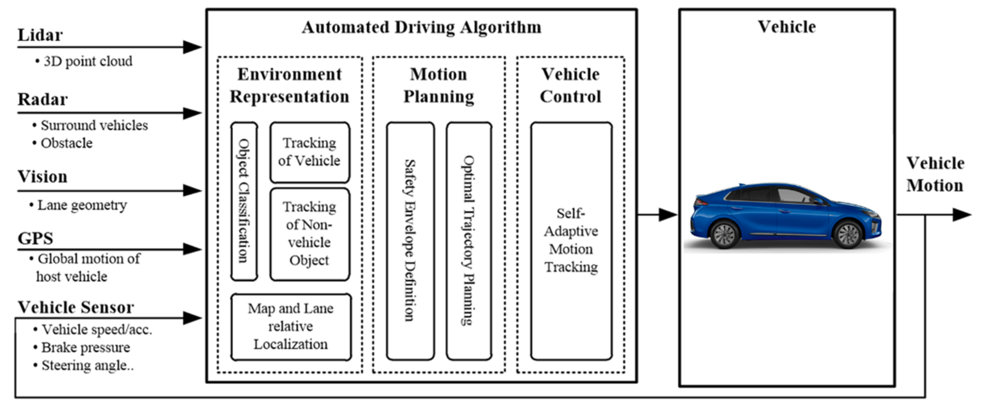
In this research, our overall automated driving control algorithm, which consists of three layers, is depicted in
Figure 1. The environment representation block estimates the global position of the ego-vehicle (called localization with commercialized sensors) and also computes collision probability and probabilistic predictions of surrounding objects. All system modules make use of information from various installed environment sensors. The main modules are vision, lidar, radar, and vehicle sensors. This information is used to predict the motions of the surrounding objects over the prediction horizon. The motion-planning part utilizes the perception result along with the predicted information of the environment to determine lane changes or to maintain the motion of the subject vehicle. The control block uses both the environment representation and planned vehicle motion to optimize the steering and longitudinal acceleration inputs to the vehicle.
2.2. Localization Algorithm Architecture
Without Differential Global Positioning System(DGPS), vehicle localization is essentially required to drive properly on the designated driving route. Therefore, a precise level of vehicle position estimation is conducted with environment sensors, GPS, and proprioceptive sensors in order to carry out vehicle control. The output of the localization part, vehicle global position, and yaw angle is delivered to the mission planner part and the vehicle control part.
The vehicle positioning process can be performed in several steps.
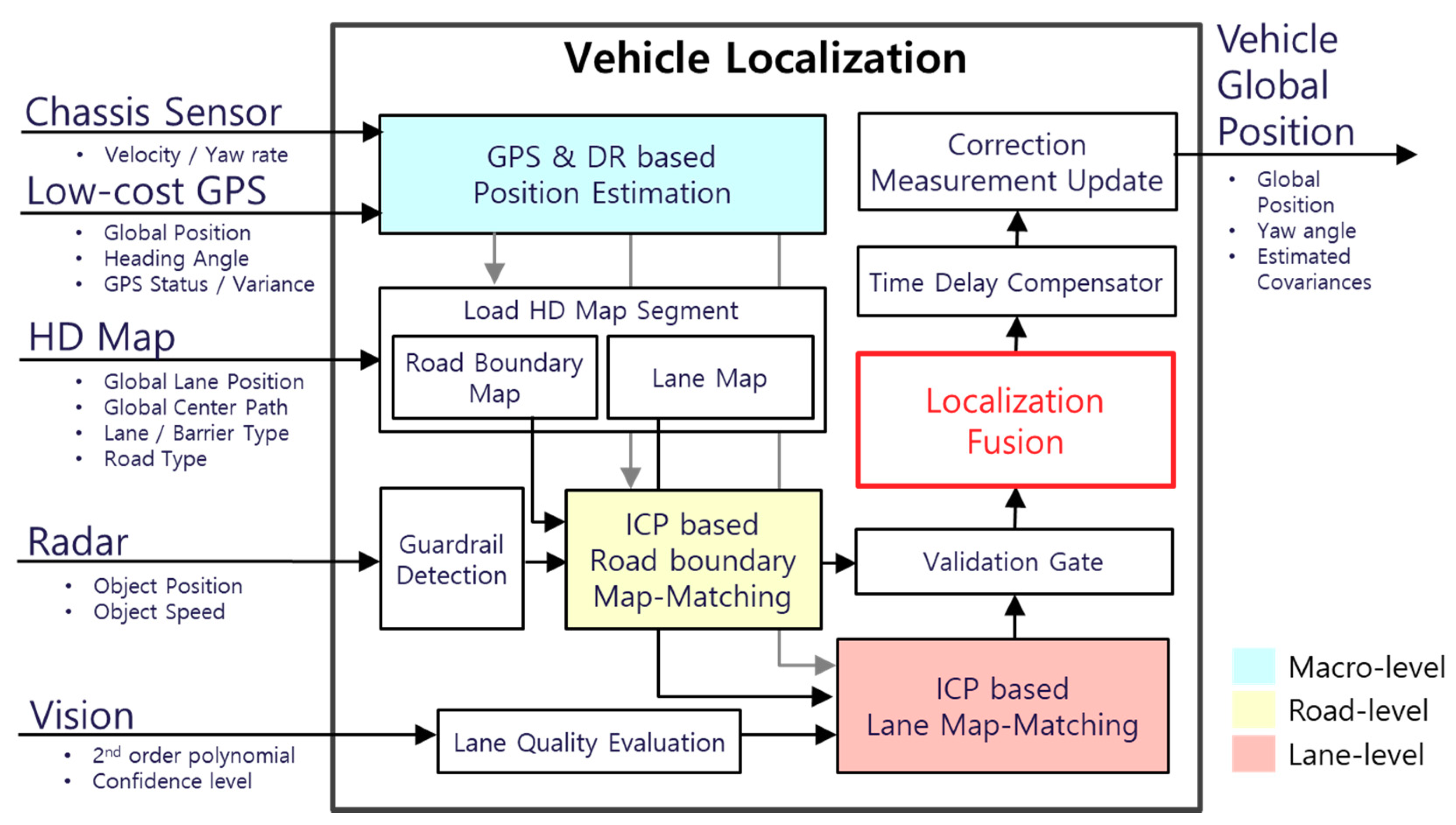
Figure 2 depicts the scheme of the proposed localization algorithm. The chassis sensor and commercial GPS are used for the dead reckoning(DR) process of vehicle position filters. Lane marks are detected by processing monocular Mobileye vision. A guardrail is perceived by the front radar by distinguishing low-speed object measurements and by accumulating several steps to extract wall features. The high definition map that we utilized for map-matching is constructed and contributed by the National Geographic Information Institute (NGII) of Korea. Then, the amount of position correction is calculated between current measurement data and the loaded map based on the iterative closest point (ICP) algorithm. The correction result of lanes and guardrails is checked by a passing validation gate in order to fuse them properly. Time delay due to the scanning rate of the sensor and system is compensated to enhance correction accuracy. Finally, the proposed algorithm provides the vehicle’s global position, yaw angle, and covariance of position estimation.
The key issues of research are considered in localization: environment detection with installed environment sensors and map-matching-based correction, fusion, and filtering.
2.3. Test Vehicle Configuration
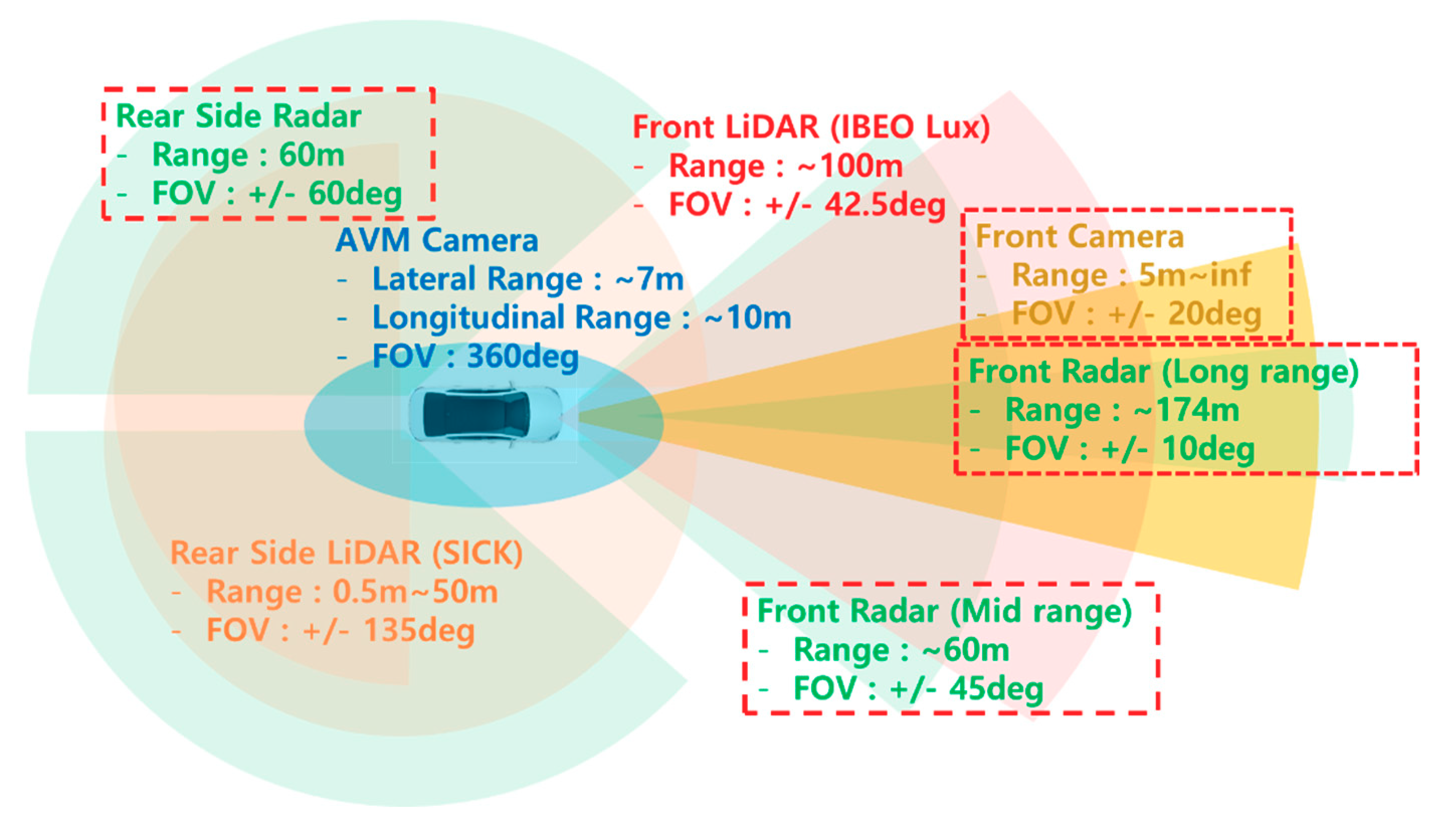
In this study, the subject vehicle was equipped with ADAS sensors, environment sensors for autonomous driving, and a reference system such as DGPS using the networked transport of RTCM via internet protocol (N-TRIP). The vehicle had long- and mid-range radar and one four-layer lidar mounted on the front bumper. Additionally, on the backside of the vehicle, two single-layer lidar and two rear-side radar were installed in order to detect rear-side objects. A monocular front vision module (Mobileye EyeQ2) was mounted on the center position of the windshield. A U-Blox EVK-M8L GPS, called low-cost GPS, was installed for macrolevel localization, and a DGPS receiver (Oxts RT3002) was also installed for the reference position of the ego-vehicle. The vehicle setups for this paper aimed to use close-to-market sensors for the much faster and more feasible realization of autonomous driving technology in the near future [
12]. We used N-TRIP as correction signals for DGPS. In addition, the DGPS is independent of the GPS position input to the system since it only serves as a reference to verify the development of algorithm performance. The throttle, brake, and steering actuators were used for vehicle automation. These systems are connected through the control area network (CAN), and the discretized command signals are transmitted on each cycle. We set up an embedded PC and MicroAutoBox as high- and low-level controllers.
Figure 3 depicts the test vehicle and the installed sensors, including detection range and field of view (FOV). For lane-level localization using ADAS commercial sensors, we used low-cost GPS, vehicle proprioceptive sensors (velocity, yaw-rate), and front vision sensors and radars. The specifications of the major sensors utilized in this research are listed in
Table 1.
3. Environment Information and HD Map
The map-matching-based position correction requires valid environment information such as lane and road boundaries (guardrail) and an HD map. In this chapter, we briefly present how we obtained point clouds of lane and guardrail signals and the characteristics of the HD map used in this approach.
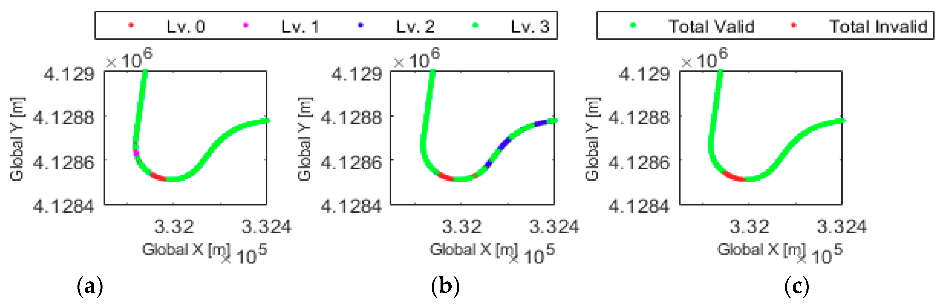
In order to detect the front lane, we obtained second-order polynomial coefficients and quality levels (0 (low)–3 (high)) of left and right lanes from the Mobileye camera (C2-170) installed at the center position of the front windshield. To prevent false detection, only signals of Quality 2 or higher were chosen for matching.
The radar points are selected as a guardrail (
) if its absolute speed is lower than 10 kph and its position exists within 20 m of the ego-vehicle center. The guardrail information (
) for use in map-matching can be obtained by accumulating points using vehicle sensor information.
where
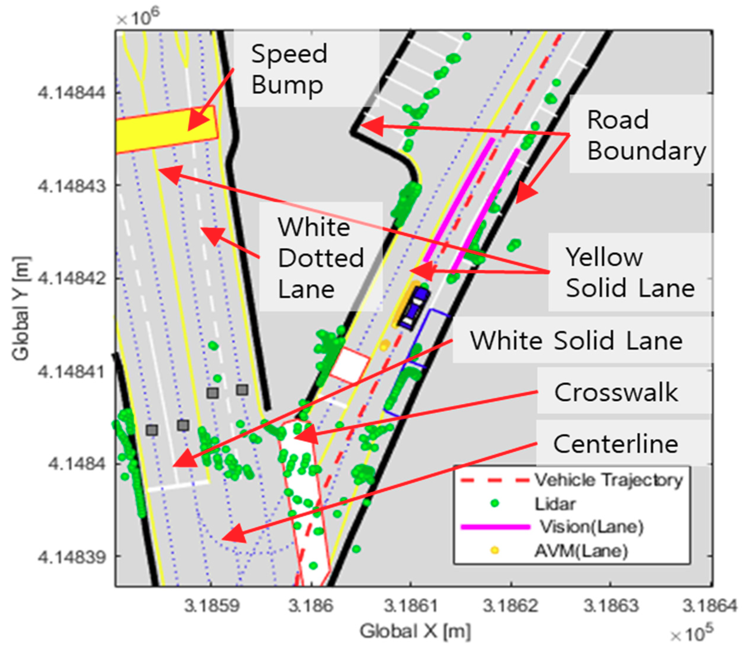
To achieve a considerable degree of position estimation by applying map-aided matching, a map with high-level accuracy is required. The map is processed from 3D-scanning information to form a vector type (*.shp) structure. The HD map contains a variety of road information such as lanes, centerlines, road (traffic) signs, road numbers, barriers, road markers, and so on. In
Figure 4, an example scene of the HD map is described. In this study, we used the position of lane and road boundaries (guardrail) information of the designated section. The HD map of the highway road section we used for position correction is produced by the Korean NGII.
4. Localization Algorithm
The several important stages of vehicle positioning are presented in this section. In order to improve the position estimation accuracy, the map-matching result can be updated with vehicle sensor data. The ICP-based map-matching results are evaluated and selected to update the estimation filter. To avoid the problem of false matching, a validation gate was designed.
4.1. ICP Based Position Correction
The position correction can be obtained by matching the digital map with the detected lane and guardrail data, which is explained in
Section 3. The high definition digital map utilized in this study is constructed by the Korean NGII in vector type. In Korea, the NGII is working on establishing a map standard by making maps available for autonomous driving.
A two-dimensional ICP algorithm is used for map-matching in order to obtain position correction information. Chen initially introduced the method of point-to-plane matching [
13]. The point-to-plane ICP algorithm searches for the best transformation between the environment representation and the map by repeating itself iteratively until the alignment error is less than a threshold. Where there is a difference in the error metric function, the point-to-plane algorithm minimizes error along the surface normal vector instead of minimizing the Euclidean distance between the road feature and the digital map. The proposed error metric function is shown as
where
shows the point clouds acquired from the environment sensors, vision, and radar, and
indicates the points of the HD map with regard to the host vehicle’s local frame.
and
represent the transformation matrices, rotation and translation, by using ICP matching. Additionally,
represents the normal surface at
.
Since we used two-dimensional matching in this study,
,
can be shown below:
where the matching result is expressed as
.
is rotation angle in radian, and
is the amount of translation in the direction of x and y of the local vehicle frame. In order to correct the vehicle position, this result will be applied. Let
represent the present global vehicle position. The result of ICP-matching obtained
is shown below:
4.2. EKF-Based Localization
The host vehicle is described with the position of points
and
and heading angle
in the global frame. The state vector,
, is expressed by
The basic framework for the EKF includes an evaluation of the states of the discretized nonlinear dynamic system, which can be derived as
where
is the process noise associated with proprioceptive sensors that is assumed to have a zero mean and a Gaussian distribution;
and
are the measurement noises of lane and guardrail matching.
indicates the external input (longitudinal speed and yaw rate) and
and
are the position corrections by each matching method.
Velocity and yaw-rate are approximately fixed during the sampling time period by integrating the Euler approximation and assuming that the control signals of the nominal discrete process model equations are derived as
where Q indicates the covariance matrix with regard to the noise of the vehicle sensor. The position of the ego-vehicle can be corrected in regular order if the corresponding matching result is valid by a measurement update, according to the following steps:
where
indicates the measurement’s covariance matrix.
The covariance matrix of the estimated state is derived as below:
The time update rate is the same as the frequency of the vehicle sensor, 100 Hz, and that of the measurement update is also the same as the vision (10 Hz) and radar (20 Hz) sampling rates.
4.3. Validation Gate
It is difficult to determine if all the position correction results of ICP maps are highly reliable. The measurement of the vehicle position computed by ICP is used as an bservation inside a Kalman filter framework. A validation gate was set up in the localization filter in order to figure out the issue of false matching by estimating the covariance of the ICP algorithm. Only the measurements of the covariance value of the ICP algorithm that properly pass the validation gate are used to update the estimator. The equations of the proposed validation gate can be obtained as follows:
where
is selected as the confidence level. The normalized error,
, differs as a chi-squared distribution with the number of measurement degrees of freedom.
are the differences between the localization results and the references.
are the error thresholds of each state, which were determined as 10.0, 3.0, and 45 degrees in this research.
5. Experimental Results
5.1. Test Route Description (Expressway Located in Korea)
Driving data were collected at the Korean Expressway in South Korea. A junction (JC) that connects two expressways exists. The maximum and minimum speed range is 100 and 60 kph, respectively. This is because the speed limit of the main highway is 100 kph and that of the JC is 60 kph due to the large curvature of the junction section. The maximum radius of the curve is 50 m. The range of the vehicle longitudinal acceleration is −2.5 to 2.5
. Although the lane recognition rate is good on most highway sections, there is a section that is lost due to the curvature of the road in the JC, which described in
Figure 5.
5.2. Result Analysis
The proposed algorithm, as explained in
Section 3, was verified by actual driving data based on offline simulation of the expressway.
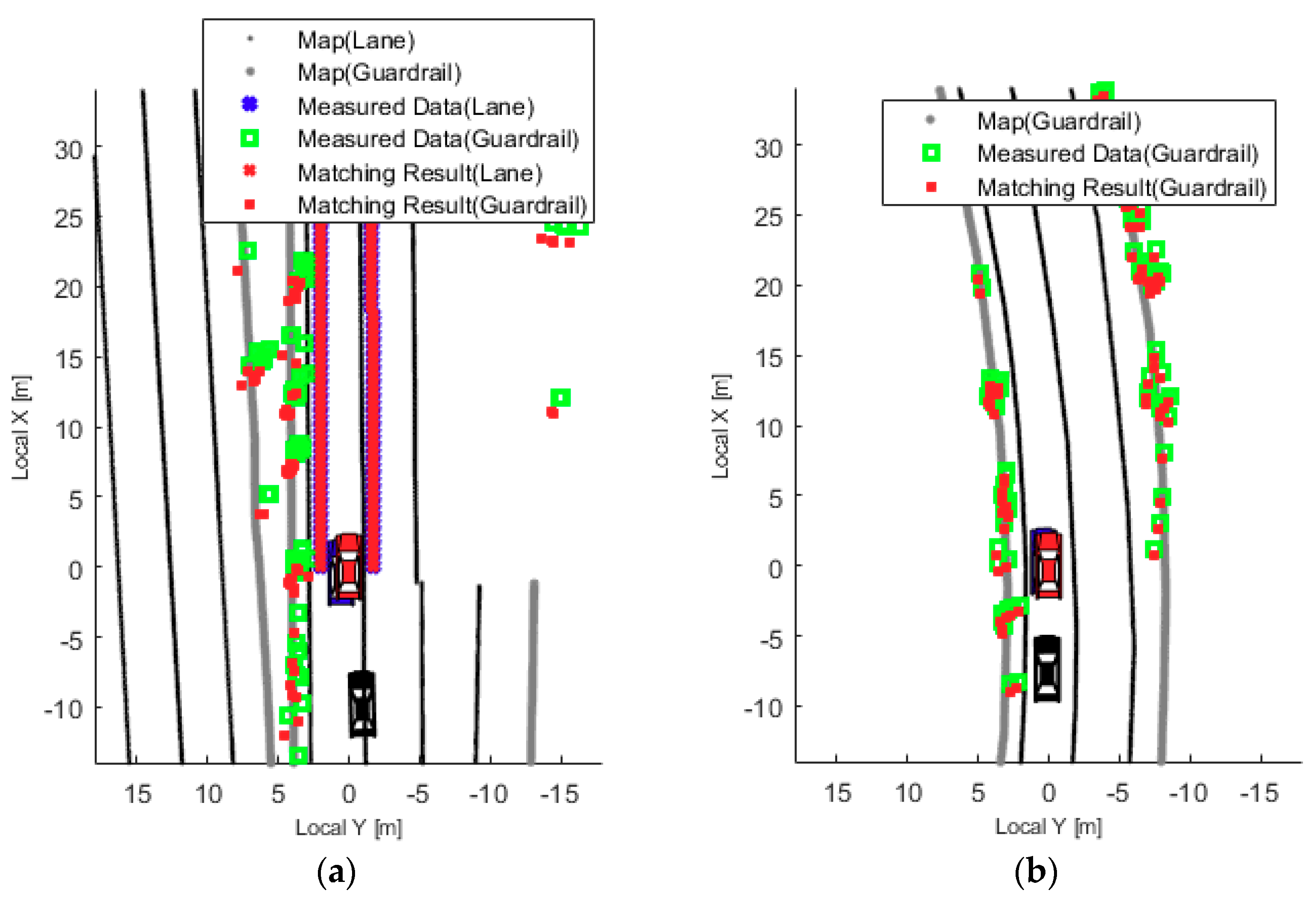
Figure 6 shows an algorithm verification scene during the simulation. The map and measurement information are shown in the legend. The lane is represented by an x-shaped marker, and the guardrail is also expressed by a square-shaped marker. The results of each position correction resulting from ICP map-matching are shown in red. The black dots express lane information of the HD map, and thick grey dots indicate the guardrail point clouds of the HD map. The global position of the proposed localization result is shown as a red car, and the raw data of GPS with simple dead reckoning and the DGPS (RT2002)-based reference global vehicle position are depicted as a black vehicle and a blue vehicle, respectively, in
Figure 6.
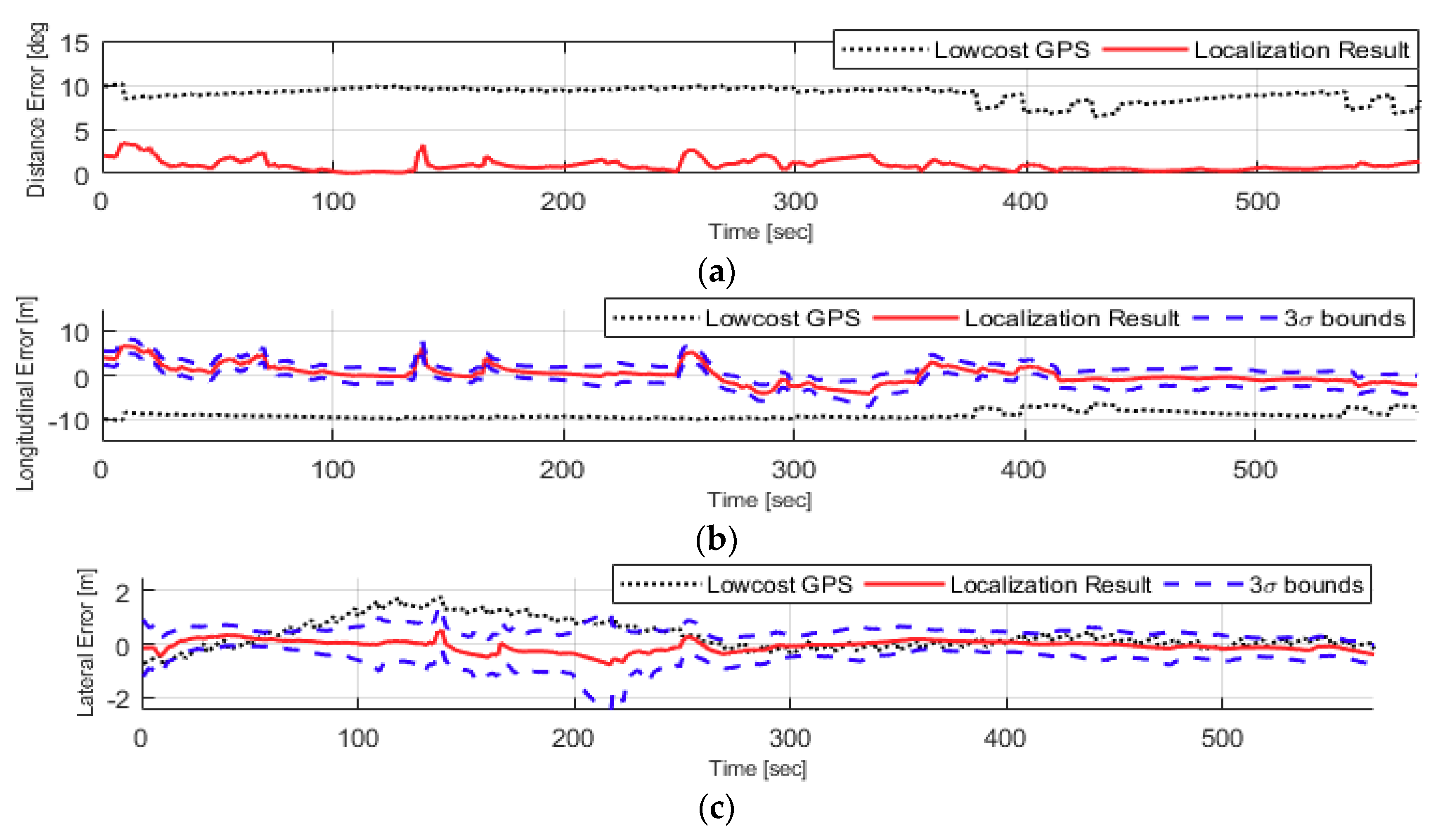
Figure 7a shows the distance error of the localization result based on reference DGPS (Oxts-RT3002) output over time.
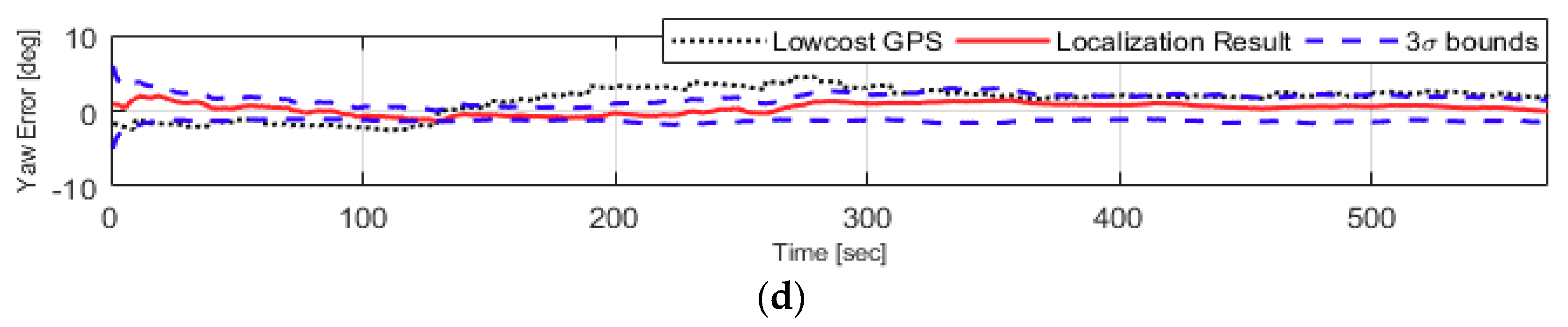
Figure 7b shows changes of localization errors on the longitudinal direction and
Figure 7c,d expresses errors on lateral and yaw angles over time for the partial section, including the junction, plotted with 3-sigma bounds (blue dashed lines) to show how the filter is well-tuned in order to estimate the vehicle’s position and posture. The four error calculations happen during a 570-s time period. For some sections that have no environment measurements or were failed to map-matching properly, the accumulated positioning error increases slightly until the proper map-matched correction is obtained. The performance of the proposed positioning algorithm enables lateral steering control to be applied safely.
6. Summary
Lane and guardrail detection-based vehicle localization using ADAS environment sensors for realizing autonomous highway driving is presented in this paper. The proposed algorithm consists of ADAS sensor-based environment representation, application of digital HD maps, map-matching-based position correction, and localization filters. In the environment representation part, we used front vision (Mobileye)-based lane detection results and extracted guardrail features by using front radar (Delphi). In addition, we used the HD map of the Korean Expressway distributed by the NGII of South Korea. We processed environment measurements such as lanes and guardrails and applied the HD map. Map-matching was conducted with the environment representation result, and then the designated filter was utilized to fuse and update the correction results. The validation gate was designed to prevent inaccuracies that might be caused by false matching results.
The positioning performance of the proposed algorithm was proven through open-loop simulation based on actual driving data. The test showed that accuracy performance within a few centimeters can be achieved for enough self-driving control. We are now in the process of applying a simulated positioning algorithm to actual vehicle tests.
Meanwhile, there are still challenging tasks of localization under various circumstances such as low visibility conditions of road markers, tunnel sections (long GPS shadow zones), lane-split sections when entering toll gates, and so forth. We will develop this algorithm of ADAS-sensor-based toll-to-toll autonomous highway self-driving and also autonomous driving technologies near commercialization by increasing the completion of autonomous driving in urban areas.
Author Contributions
Conceptualization, D.S. and K.-m.P.; methodology, D.S.; software, D.S.; validation, D.S. and K.-m.P.; formal analysis, D.S.; investigation, M.P. and K.-m.P.; resources, D.S.; data curation, M.P.; writing—original draft preparation, D.S.; writing—review and editing, M.P.; visualization, D.S.; supervision, M.P.; project administration, M.P.; funding acquisition, M.P. All authors have read and agreed to the published version of the manuscript.
Funding
This work was supported by a Road Traffic Authority grant funded by the Korea government (KNPA; POLICE-L-00003-02-101, Development of Information Provision Technology with IoT-based Traffic Control Devices and Its Operation Management), the Basic Science Research Program through the National Research Foundation of Korea (NRF) funded by the Ministry of Education (2018R1D1A1B0704814313), and Sookmyung Women’s University Research Grants (1-2003-2008).
Acknowledgments
This work was supported by a Road Traffic Authority grant funded by the Korea government (KNPA; POLICE-L-00003-02-101, Development of Information Provision Technology with IoT-based Traffic Control Devices and Its Operation Management), the Basic Science Research Program through the National Research Foundation of Korea (NRF) funded by the Ministry of Education (2018R1D1A1B0704814313), and Sookmyung Women’s University Research Grants (1-2003-2008).
Conflicts of Interest
The authors declare no conflicts of interest.
References
- Shin, D.; Kim, H.; Park, K.; Yi, K. Development of Deep Learning Based Human-Centered Threat Assessment for Application to Automated Driving Vehicle. Appl. Sci. 2020, 10, 253. [Google Scholar] [CrossRef] [Green Version]
- Shin, D.; Yi, S.; Park, K.; Park, M. An Interacting Multiple Model Approach for Target Intent Estimation at Urban Intersection for Application to Automated Driving Vehicle. Appl. Sci. 2020, 10, 2138. [Google Scholar] [CrossRef] [Green Version]
- Skog, I.; Handel, P. In-car positioning and navigation technologies—A survey. IEEE Trans. Intell. Transp. Syst. 2009, 10, 4–21. [Google Scholar] [CrossRef]
- Adam, C.; Schubert, R.; Mattern, N.; Wanielik, G. Probabilistic road estimation and lane association using radar detections. In Proceedings of the 14th International Conference on Information Fusion, Chicago, IL, USA, 5–8 July 2011; pp. 1–8. [Google Scholar]
- Han, S.-B.; Kim, J.-H.; Myung, H. Landmark-based particle localization algorithm for mobile robots with a fish-eye vision system. IEEE/ASME Trans. Mechatron. 2012, 18, 1745–1756. [Google Scholar] [CrossRef]
- Schreiber, M.; Knöppel, C.; Franke, U. Laneloc: Lane marking based localization using highly accurate maps. In Proceedings of the 2013 IEEE Intelligent Vehicles Symposium (IV), Gold Coast, Australia, 26–28 June 2013; pp. 449–454. [Google Scholar]
- Tao, Z.; Bonnifait, P.; Fremont, V.; Ibanez-Guzman, J. Lane marking aided vehicle localization. In Proceedings of the 16th International IEEE Conference on Intelligent Transportation Systems (ITSC 2013), The Hague, The Netherlands, 6–9 October 2013; pp. 1509–1515. [Google Scholar]
- Weber, Y.; Kanarachos, S. The correlation between vehicle vertical dynamics and deep learning-based visual target state estimation: A sensitivity study. Sensors 2019, 19, 4870. [Google Scholar] [CrossRef] [PubMed] [Green Version]
- Hata, A.Y.; Osorio, F.S.; Wolf, D.F. Robust curb detection and vehicle localization in urban environments. In Proceedings of the 2014 IEEE Intelligent Vehicles Symposium Proceedings, Ypsilanti, MI, USA, 8–11 June 2014; pp. 1257–1262. [Google Scholar]
- Besl, P.J.; McKay, N.D. Method for registration of 3-D shapes. IEEE Trans. Pattern Analysis Mach. Intell. 1992, 14, 239–256. [Google Scholar] [CrossRef]
- Park, S.-Y.; Subbarao, M. An accurate and fast point-to-plane registration technique. Pattern Recognit. Lett. 2003, 24, 2967–2976. [Google Scholar] [CrossRef]
- Furgale, P.; Schwesinger, U.; Rufli, M.; Derendarz, W.; Grimmett, H.; Mühlfellner, P.; Wonneberger, S.; Timpner, J.; Rottmann, S.; Li, B. Toward automated driving in cities using close-to-market sensors: An overview of the v-charge project. In Proceedings of the 2013 IEEE Intelligent Vehicles Symposium (IV), Gold Coast, Australia, 26–28 June 2013; pp. 809–816. [Google Scholar]
- Chen, Y.; Medioni, G.G. Object modeling by registration of multiple range images. Image Vis. Comput. 1992, 10, 145–155. [Google Scholar] [CrossRef]
© 2020 by the authors. Licensee MDPI, Basel, Switzerland. This article is an open access article distributed under the terms and conditions of the Creative Commons Attribution (CC BY) license (http://creativecommons.org/licenses/by/4.0/).


