1. Introduction
The evolution of tall buildings has undergone remarkable developments in the last century. The first buildings reaching a few tens of stories were first built in the United States in the late 19th century, mostly in the cities of New York and Chicago. At the beginning of the 20th century, a race for the realization of the tallest skyscrapers took place, which led to the completion of the 102-story tall Empire State Building in 1931 (
Figure 1a). Although at that time the height of those buildings was worthy of note, their realization was not achieved by means of significant technological innovations. They usually employed the same steel frames which were adopted for shorter buildings, leading to excessive material usage and rather over-designed solutions [
1]. Bracings were employed to withstand lateral loads arising from wind pressures and earthquake actions. It was already recognized that lateral actions usually govern the design solutions in tall buildings. In fact, as the building becomes taller, the lateral drifts turn out to be more critical, and there is greater demand for suitable structural systems to carry lateral forces. This leads to a dramatic increase of material consumption with the increase in the number of stories, which is usually referred to as the “premium for height” [
1,
2].
Due to aesthetic and constructability considerations, the bracings were usually embedded within the interior core of the building. Although their shear resistance, based on the axial deformation of the diagonals, was beneficial in resisting the lateral actions, compared to the mechanism of the conventional moment resisting frames, their placement within the interior of the building prevented their effective employment in withstanding the overturning moment. Therefore, new solutions exploiting bracings on the external perimeter of the building were developed. One of the first examples was the 100-story tall John Hancock Center built in Chicago in 1970 (
Figure 1b). The John Hancock is an example of braced tube, where the mega-diagonals spanning over several stories are effective in resisting the shear and bending moment deriving from lateral actions. The braced tube was a variation of the typical framed tube, where closely spaced perimeter columns were in charge of providing the necessary lateral stiffness. The adoption of mega-diagonals on the external surface offered higher lateral stiffness, while reducing some detrimental phenomena of the framed tube, such as the shear-lag effect. With this new solution, a greater number of stories and an overall enhanced structural performance could be achieved, leading also to important advantages from a material consumption perspective.
Based on the structural behavior of the braced tube, where vertical columns and external bracings were designed to carry gravity and lateral loads respectively, it was realized that the external mega-diagonals were able to resist vertical and horizontal loads simultaneously, without the need for conventional vertical columns. This led to the realization of the diagrid (“diagonal” + “grid”) structural system.
The idea of removing vertical columns and considering only inclined diagonals was not new. As a matter of fact, the first diagrid structure was realized before the construction of the John Hancock braced tube, in the 1920s, by the Russian architect Vladimir Shukhov, for the realization of a broadcasting tower in Moscow [
3]. The external pattern, made up of a triangular tessellation, allowed the reduction of the wind load while reaching a stable stiff configuration. The first application of a diagrid system in building design occurred in the 1960s, with the completion of the 13-story tall IBM Building (Pittsburgh, USA). The steel diagrid exoskeleton was integrated with the glazing system, and assisted in the overall stability of the building [
3].
However, it was not until the early 21st century that diagrid systems started to be thoroughly applied in the design and construction of tall buildings. The first examples are the Hearst Tower in New York (
Figure 2a) and the 30 St. Mary Axe (also known as Swiss Re Tower or The Gherkin) in London (
Figure 2b), both by Sir Norman Foster. These buildings reached 180 m and provided the first references for the suitability of diagrid systems in tall building design. Thanks to the stiff diagrid façades, which create a pleasant diamond-like pattern, the Hearst Tower was realized using 20% less steel than an equivalent conventional moment frame structure [
4]. The aerodynamic form of the Swiss Re Tower, obtained through an external free-form diagrid envelope, allowed the reduction of wind action on the building, and led to column-free flexible internal spaces [
5]. These two examples already showed the valuable features of diagrids for tall buildings: enhanced structural performance, saving of material consumption compared to traditional solutions, and significant aesthetic potential.
Many diagrid structures were realized worldwide in the following years, where various forms and shapes were adopted for the external diagrid façades. Among others, examples worthy of note are the Guangzhou Financial Center, the CCTV Tower and the Poly International Plaza in China, the Tornado Tower (
Figure 2c) in Qatar, the Capital Gate in Arab Emirates, and the Bow Tower in Canada [
3]. Nowadays, most of the built diagrid structures are made of steel, mostly due to the easier and faster construction, simpler joints and less expensive formworks [
3]. However, concrete and composite diagrids are also experiencing an increasing popularity, as they allow the realization of even more complex-shaped diagrid patterns, e.g., the O-14 Building in Dubai [
6].
The significant use of diagrid systems in recent tall buildings is mainly due to the following reasons:
- (1)
high lateral stiffness (thus low lateral deformability), which allowed the reaching of the lateral deflection limit target using a lower amount of structural material compared to other conventional systems;
- (2)
architectural flexibility, allowing a more rational use of the interior space with fewer columns;
- (3)
modularity, which led to the realization of complex-shaped structures of various forms.
These three points arise from the successful use of the triangular module coupled with the inherent structural performance of the tubular structure [
7,
8].
The triangular element, which is made up of two inclined diagonals and a ring beam, is the basic component of the diagrid façade. The diagonals carry the vertical and lateral loads mostly by axial forces (compression or tension). For this reason, they are usually pinned at the panel nodes, as reflected in
Figure 3a. Since the inclined diagonals often extend over multiple stories, the external floor beams of intermediate stories are often supported by the diagonals, which consequently induces slight shear and bending stresses on them. However, in preliminary design stages, these are usually neglected when compared to the high axial stresses arising from the vertical and lateral loads on the building. Note that in
Figure 3a, a 3-story module is reported, as the height of each diagrid module has the same height as a triangular element. In other research works, as will be shown in further figures in the remainder of the paper, the diagrid module is defined in such a way that it covers two triangular elements.
In
Figure 3b, the three-dimensional view of the tubular diagrid structure is shown, as reported in [
9]. Usually, the tube-in-tube configuration is found in real diagrid buildings, where an internal (concrete or steel braced) core is coupled with the external diagrid tube. In preliminary design stages, the diagrid is usually designed to carry the lateral actions alone, while the internal core is designed only for gravity loads. However, further details of the diagrid–core interaction will be shown in the remainder of the paper.
Hence, it is the combination of the axial resisting mechanism of the triangular element—characterized by modularity and arrangement flexibility—coupled with the structural efficiency of the tubular configuration, that has ultimately led to the success of the diagrids in recent times.
In this paper, a thorough and up-to-date survey of the research studies on diagrid systems is reported. In particular, in
Section 2, the fundamental stiffness-based approach of the preliminary design is described, as firstly proposed by Moon et al. [
10] and further developed in the following years. Moreover, strength-based design methodologies are also discussed, and their implication for the preliminary design is analyzed.
Section 3 describes the various methodologies available today, besides the typical Finite Element Method (FEM), for the structural analysis of diagrid structures in preliminary design stages, e.g., hand-based calculations, modular and matrix-based methods, etc. In
Section 4, the subject related to the optimization of the diagrid performance based on its geometrical features is also addressed. This problem has been thoroughly tackled by various researchers in the last decade, with different methodologies, and has led to significant results.
Section 5 describes the problem of local structural issues in the design of diagrid tall buildings, e.g., excessive inter-story drifts and stability of interior columns. The mathematical formulation for identifying these problems is reported, as well as the solutions which have been suggested to tackle them, such as the insertion of secondary bracing systems (SBSs), as was first proposed by Montuori et al. [
11]. In
Section 6, the shear-lag phenomenon in diagrid tubes is discussed and its influence, depending on the diagrid’s geometrical parameters, is analyzed.
Section 7 also discusses the research studies which have dealt with the nonlinear behavior of diagrid tubes, in order to assess their seismic and robustness performance. In
Section 8, the recent research on diagrid nodes, which represents a crucial component in the correct behavior of the diagrid, is also reported.
Section 9 provides comments about the new trends regarding unconventional diagrids, which are applied in the realization of twisted, tilted, tapered and freeform buildings. A further evolution of the grid tubular structure, which has experienced a significant growth in recent tall building design, is finally presented in
Section 10.
2. Simplified Approaches to the Preliminary Design of Diagrid Tubes
The first simplified stiffness-based approach to the preliminary design of diagrid systems was proposed by Moon et al. in 2007 [
10]. It is based on the evaluation of the shear and bending stiffness of the diagrid modules, aimed at limiting the lateral deflection of the structure. The building is treated as a vertical cantilever beam, fixed on the ground and subjected to lateral loads. Accordingly, the building undergoes horizontal displacements, which depend on the stiffness of the diagrid tubular structure. For the sake of the preliminary design, the contribution of the internal cores to the lateral stiffness of the building is neglected, as they are only designed to carry gravity loads.
The elementary diagrid module is depicted in
Figure 4. The diagrid module covers a height
h with two triangular elements. The diagonals have a length
Ld, and their inclination with respect to the horizontal plane is
θ. Depending on the loading direction, each façade can act either as a web or a flange.
Vi and
Mi are the shear force and bending moment acting on the level of the
ith module. These are carried by the web and flange diagonals, respectively. Diagonals are assumed to be pinned at their end, thus carrying only axial force, and remain in the linear elastic regime. In this way, the cross-sectional areas of the web and flange members are the only factors that need to be obtained in order to accomplish the preliminary design.
The shear stiffness
KT,i and bending stiffness
KB,i of the
ith diagrid module link the shear force
Vi and bending moment
Mi to the module displacement Δ
ui and rotation Δ
βi, respectively. By applying compatibility, constitutive and equilibrium equations,
KT,i and
KB,i are obtained as follows:
where
Nw and
Nf are the total number of diagonals in the web and flange façade, respectively,
Ad,w,i and
Ad,f,i the cross-sectional area of the web and flange members,
E the elastic modulus of the diagonals and
B the web dimension. The displacement Δ
ui and rotation Δ
βi are equal to the product of the module height
h and the shear and bending deformation,
γ and
χ, respectively. Specifying the desired values of shear and bending deformation,
γ* and
χ*, the member dimensions can be easily obtained as [
10]:
Since the horizontal load can act in either direction, the maximum value of the cross-sectional areas from Equations (3) and (4) should be assigned to each diagonal, which can act as either a web or flange member. The desired values of
γ* and
χ* are specified based on the desired deformation mode of the building. Assuming that the building sway mechanism is equivalent to the deformation of a cantilever beam, the lateral deflection at the top of the building
u(H) can be written as follows:
where
γ*H and
χ*H2/
2 are the shear and bending contribution, respectively. In order to assess the relative contribution of bending versus shear deformation, Moon et al. [
10] introduce a non-dimensional parameter
s, given by the ratio of the bending to the shear contribution, i.e.:
Combining Equations (5) and (6), and considering that the top lateral displacement is usually specified as a fraction of the total building height, i.e.,
u(H) =
H/
α (
α usually being 500), one obtains the following relations between
γ*,
χ* and
s:
Substituting Equations (7) and (8) into Equations (3) and (4), the member sizes can be obtained for the different values of the parameters.
Adopting different
s values leads to different preliminary sizing for the external diagonals. When
s is extremely low, the shear deformation mode of the structure prevails over the bending mode, and this leads to excessive material usage in the flange members to limit the bending deflection. Conversely, when
s is high, the bending deformation prevails, and the obtained cross-sectional areas are mainly governed by the web façades to limit the shear deformability. Therefore, an optimal value of
s is shown to exist,
sopt, which balances the need to limit both shear and bending deformability [
10]. In this case, the member sizes at the higher stories are usually governed by the shear deformation, while the ones at the lower stories are mostly controlled by the bending deformation. The
sopt depends on the building aspect ratio—(
H/
B)—and leads to the most efficient solutions that comply with the target maximum displacement while employing the minimum amount of material. For diagrid structures taller than 40 stories, with
H/
B greater than 5 and diagonal angles between 60° and 70°, the empirical equation
sopt =
H/
B − 3 is proposed [
10].
The other fundamental parameter that plays a key role in the preliminary design of diagrids is the diagonal inclination. Investigating a set of 20- to 60-story tall buildings, Moon et al. show that, for diagrid structures with aspect ratios of about 7, the optimal angle is between 65° and 75°, whereas for diagrids with aspect ratios of about 5 the optimal angle is lower, at around 10° [
10]. This is due to the competition between shear and bending stiffnesses in governing the deformation mode, and their dependence on the diagonal angle. Shear rigidity is at a maximum when the inclination is about 35°, while bending rigidity achieves its maximum value when the elements are vertical, i.e.,
θ = 90°. The optimal value for maximizing both shear and bending rigidity lies between these two. Since shear mechanism prevails in shorter buildings and bending prevails in taller ones, it is expected that, as the aspect ratio increases, the building behaves more like a bending beam, and the optimal angle thus increases [
10]. This consideration has been strongly exploited in the analysis and design of diagrid systems, by considering various angle-based strategies and patterns for optimizing the diagrid performance. More details about this subject are reported in
Section 4.
The same stiffness-based approach reported in the previous paragraphs is also applied by Moon to braced tubes in [
12]. In this case, the shear force is carried by the external mega-diagonals, while the bending moment is carried by the perimeter vertical columns. Analyses based on 40- to 100-story tall braced tubes show that the optimal angle in this case is close to 45°, and is less dependent on the building aspect ratio. This is due to the negligible involvement of external diagonals in carrying bending moment. For braced tubes with an aspect ratio greater than 6, Moon suggests a different empirical equation for the optimal
s value, i.e.,
sopt =
H/
2B − 1 [
12]. It has to be noted that, in the same paper, the same analysis has been applied to diagrids with a broader range of heights than previously analyzed, i.e., from 40 to 100 stories. As a result, the author proposes a new empirical equation for the
sopt for diagrid structures with aspect ratios greater than 6, i.e.,
sopt =
H/
B − 2.
In the cases investigated by Moon [
10,
12], it is found that the stiffness requirements drive the preliminary design, and the strength criteria are usually fulfilled. Only a few members in the leeward façade of the building are found to fail when the maximum allowable displacement is increased, i.e.,
α < 500. However, thanks to the high rigidity of the diagonalized façades, which make the diagrid structure highly efficient, strength requirements may be of paramount importance, and in specific cases, they might even govern the design criteria, as suggested by Montuori et al. in [
13]. In this paper, a simplified strength-based methodology for the preliminary design of diagrid tubes is provided.
Figure 5 shows the adopted scheme for the development of the strength-based approach. Both gravity and lateral loads are applied to the building.
Assuming that the internal core occupies 25% of the floor area, the diagrid carries 37.5% of the gravity load at the level of the m
th module,
Qm (
Figure 5a). This vertical loading condition generates a uniform compression state in all the
nk diagonals of the module,
Nm,k,Q = 0.375
Qmsinθ/
2nk. Lateral loads generate the bending moment
Mm and shear force
Vm at the module level. The former induces a uniform compression state in the diagonals of the leeward flange, a uniform tension state in the windward flange and a linear distribution of tension–compression axial forces in the webs, depending on the distance
di of the
ith diagonal from the center of the floor (
Figure 5b). This leads to the expression of the axial force
Nm,k,M = ±
Mmdksinθ/
2Σdi. Conversely, the shear force induces only tension–compression stresses in the web diagonals, therefore
Nm,k,V = ±
Vmcosαkcosθ/
2Σcosαi,
α being the direction of the horizontal force with respect to the orientation of the diagrid module (
Figure 5c).
Considering all the loading conditions, one obtains the total axial force in the generic diagonal, as Nm,k = Nm,k,Q + Nm,k,M + Nm,k,V. This value is finally used to define the member size, based on the tensile strength and the buckling compressive resistance of the diagonal. In the same paper, the authors also propose an analytical formulation, based on the Euler–Bernoulli and Timoshenko beam theories, to obtain an alternative optimal s value for the stiffness-based approach, i.e., sopt = 0.19H2/tanθL2.
The strength- and stiffness-based approaches are simultaneously applied in the preliminary design of a rectangular, 100-story tall diagrid tube, considering three different diagonal angles (64°, 69° and 79°), under both gravity and wind loads. The results show that, on the broad side of the building, strength requirements always prevail at the upper modules, whereas stiffness criteria drive the design of the lower modules. Conversely, on the shorter side, strength prevails over stiffness for the entire height of the building with
θ = 64°, and stiffness prevails for
θ = 79°, while in the case of 69° (which is close to the optimal angle inclination) the stiffness- and strength-based approaches provide almost the same result [
13].
After carrying out the structural analyses on the designed buildings, it is found that the stiffness-based methodology leads to very efficient structures as regards the top lateral deflection, which is very close to the target value. However, this approach usually leads to unsatisfactory results in terms of the inter-story drift of the upper modules, as well as in terms of member strength demand-to-capacity ratio (DCR). In fact, besides the case of
θ = 79°, where only 0.3% of the diagonals fail the strength requirements, 26% and 23% of them exhibit DCR greater than 1, for
θ = 64° and 69°, respectively. On the contrary, adopting the strength-based design, the fraction of elements with DCR greater than 1 is 0%, 0.5% and 0.3%, for
θ = 64°, 69° and 79°, respectively. However, with this approach, unsatisfactory results are obtained in terms of lateral deformability, especially in the case of 69° and 79° [
13]. Therefore, stiffness-based approaches might lead to unsatisfactory strength results, while strength criteria might fail stiffness requirements. A compromise should then be found depending on the specific building characteristics. In both cases, large inter-story drifts are usually found at the upper modules. This issue has been thoroughly analyzed by Montuori et al. [
11], and tackled by providing special internal systems, like SBSs. More details on this will be provided in
Section 5.
Further investigation regarding the suitability of stiffness- and strength-based criteria for the preliminary design is subsequently developed in a broader range of diagrid structures [
14,
15]. In [
14], Mele investigates the effect of both approaches on 90-story tall diagrid tubes, with diagonal angles of 60°, 70° and 80°. The results are in line with the previous findings. For smaller diagonal angles, strength usually drives the design, while the stiffness-based approach leads to inadequate DCR values. For greater angles, the stiffness-based design prevails, while strength criteria lead to excessive lateral deflections. In the range of the optimal angle, both criteria concur in defining the member sizes.
More recently, the effect of both slenderness and diagonal angle has been taken into account simultaneously for the preliminary design [
15]. Diagrids with aspect ratios ranging from 2 to 8, and diagonal angles from 50° to 80°, are considered. It is found that, for those with an aspect ratio from 2 to 4, the design is mainly governed by strength requirements, independently of the diagrid angle, and the “premium for height” is mostly linear with the increase of slenderness. Conversely, for aspect ratios greater than 6, the design is mainly driven by stiffness, and the weight increases more than linearly with the slenderness. Aspect ratios around 5 are found to be the threshold, where stiffness- and strength-based designs provide comparable solutions [
15].
Based on these results, it is concluded that, due to the extreme rigidity of the diagrid tubular system, it is not always possible to know a priori whether stiffness- or strength-based criteria should be considered for the preliminary design. Both approaches are necessary and unavoidable, and none of them should be used without the other [
13]. The geometrical diagrid parameters—e.g., building aspect ratio and diagonal angle—drive the prevalence of one over the other. In any case, simplified approaches for the preliminary design represent an effective way to quickly define and assess the structural characteristics and performance of the diagrid.
3. Methods for the Structural Analysis of Diagrid Tall Buildings
In the academic literature, the most common procedure for dealing with the structural analysis of diagrid systems is the Finite Element Method (FEM). However, simplified methodologies have also been developed for a quick evaluation of the diagrid’s overall structural behavior.
Mele et al. [
16] have proposed a hand-based method for the evaluation of the axial stress in the diagrid members. The method is based on the analysis of the internal forces arising in the basic triangular element due to gravity and vertical loads, taking also into account the effect of the horizontal and vertical curvatures of the diagrid façade. Although it does not allow the direct calculation of the displacements of the structure, this methodology has proven effective in the computation of the axial forces in the diagonals. It is applied to three real case studies, the Swiss Re Building (London), the Hearst Headquarters (New York) and West Tower (Guangzhou), and the axial stresses arising from hand-calculations show a very good correspondence with FEM results. Design considerations regarding the optimal diagonal inclination for the investigated cases are also provided.
More recently, Liu and Ma have developed a simplified methodology, called the modular method (MM), for performing the structural analysis of diagrid tubes with an arbitrary polygonal shape [
17]. So far, most of the research has been focused on rectangular diagrids, having vertical façades acting as webs or flanges (
Figure 4 and
Figure 5); however, little attention has been paid to diagrids with polygonal shapes.
The modular method relies on the modularization of the diagrid, and the calculation of the lateral stiffness of the diagrid modules in order to compute the total lateral deflection. The lateral displacement
ui of the
ith module can be obtained by superimposing the contribution of the shear displacement
uV,i and bending displacement
uM,i. Based on the evaluation of the shear and bending rigidity of the
ith module,
KV,i and
KM,i, the two contributions can be computed as follows:
where
Vi and
Mi are the shear force and bending moment at the level of the
ith module, respectively, and
h the height of the module. The key to the MM is the calculation of the shear and bending rigidities,
KV,i and
KM,i, which is based on the usual assumptions for diagrid tubes: the diagonals are only subjected to axial stress and remain in the linear elastic regime; the building floors behave as rigid bodies without any internal deformation; the intra-module floors are neglected for the calculation of the modular rigidities.
Shear rigidity is defined as the total shear force
FV required for unitary horizontal displacement of the module Δ
v (
Figure 6a), and bending rigidity is defined as the bending moment
M required for unitary floor rotation Δ
β (
Figure 6b). Applying independently unitary floor displacements and rotations, and computing the total shear force and bending moment, leads to the direct evaluation of
KV,i and
KM,i. The calculation of the shear force and bending moment is based on the geometrical compatibility equations, the constitutive relations of the diagonals, and finally the equilibrium equations at the level of the floor. This finally allows one to obtain the following formulations for
KV and
KM:
where
E and
A are the Young modulus and cross-sectional areas of the diagonals,
θ the angle between the diagonal and the main ring beam in the façade,
γ the angle between the ring beam plane and the façade,
N the number of total diagonals in the module,
α the angle between the ring beam and shear direction, and
Bd is the distance between the diagonal
d and the neutral axis in the main ring beam plane [
17]. Note that Equations (11) and (12) resemble Equations (1) and (2), but they also include the effect of not-vertical façades (
γ angle) and polygonal planar shapes (
α angle). Making use of Equations (11) and (12) for each module, together with the application of Equations (9) and (10), one can finally evaluate the lateral deformation of the diagrid building under horizontal loads.
The MM is verified against FEM calculations, analyzing square, hexagonal and octagonal diagrid tubes with vertical and inclined façades under different horizontal loading conditions. The variations, in terms of top displacement, from the FEM results are always within 10%, which verifies the proposed methodology. Based on the evaluation of the shear and bending rigidities, the MM is also employed to define the analytical framework for the preliminary design of diagrids [
17].
Subsequently, a new method has been developed for the structural analysis of diagrids by Lacidogna et al., in 2019 [
18], which has been called the matrix-based method (MBM). This methodology is grounded in matrix calculus and is similar to the FE method, although it drastically reduces the degrees of freedom (DOFs) of the diagrid structure. It is based on the same assumptions employed by the previous authors [
10,
17]: the diagonals carry only axial force and remain in linear elastic regime, the intra-module floors are neglected and the building deformation obeys the plane section assumption. The major reduction in the system DOFs, compared to conventional FE models, is due to the fact that, under the above assumptions, the considered DOFs in the MBM are only the displacements and rotations of the rigid floors, rather than considering the nodal displacements and rotations associated with all the structural elements.
The structural problem for the 3D free-form diagrid tubes is formulated through the generalized Hooke’s law, as {
F} = [
K]{
δ}, {
F} and {
δ} being the force and displacement vectors, respectively, and [
K] the stiffness matrix of the diagrid. Considering a number of floors equal to
N, the total dimension of the structural problem is
6N × 6N, six being the number of DOFs per floor, i.e., three translations and three rotations. The matrix equation can be expanded as follows, where all the DOFs contributions are highlighted:
In Equation (13) {
Fx}, {
Fy} and {
Fz} represent the forces acting at the floor level in the horizontal (X, Y) and vertical (Z) direction, respectively, and {
δx}, {
δy} and {
δz} are the corresponding displacements. {
Mx} and {
My} contain the out-of-plane moments acting in the X and Y directions, respectively, while {
φx} and {
φy} are the corresponding out-of-plane rotations. Finally, {
Mz} and {
φz} denote the torque moments and rotations acting around the vertical axis. Based on the expansion of the force and displacement vectors reported in Equation (13), the
6N ×
6N stiffness matrix is partitioned accordingly, where each
N ×
N submatrix relates a force–moment vector to the generic displacement–rotation vector. The procedure for the calculation of the stiffness matrices is grounded in the displacements method, and is similar to the scheme adopted by Liu and Ma in the MM [
17]. The stiffness coefficients are obtained by applying unitary displacement–rotations at the floor levels, and evaluating the total reacting force–moments according to the compatibility, constitutive and equilibrium equations.
The MBM is more general than the MM, since it does not only consider shear and bending rigidities (contained in the matrices [KFx,δx], [KFy,δy], [KMx,φx] and [KMx, φx]), but also the vertical and torsional ones, i.e., [KFz,δz] and [KMz,φz]. Besides these 6 sub-matrices that lie on the diagonal of the stiffness matrix, the MBM also evaluates another 30 mixed submatrices, although only 15 of them need to be computed due to the symmetry properties of [K]. For regular-form diagrids, most of these out-of-diagonal matrices are zero; nevertheless, the evaluation of the matrices [KFx,φx], [KFy,φy], [KMx,δx] and [KMx,δy] is extremely important, as they contain the information regarding the coupling between shear and bending stiffnesses, and therefore concur with the correct definition of the lateral deflection.
After the complete calculation of the stiffness coefficients of the 21 non-identical submatrices in Equation (13), the application of forces and moments at the floor levels leads to the evaluation of the corresponding displacements and rotations, through the inversion of Equation (13). Eventually, knowing the deformation of the structure, the compatibility and constitutive equations are applied once again, in order to find the axial forces in the diagonals. The MBM is applied to perform the structural analysis of the double-curvature Swiss Re Tower, and comparisons with FEM calculations show the consistency of the suggested method in the evaluation of both lateral and vertical displacements, as well as torsional rotations [
18].
The MBM has not only been developed for the structural analysis of diagrids, but also to investigate the interaction between a diagrid tube and other resisting elements embedded within the building. To do so, the MBM has been built within the framework of the General Algorithm (GA), a matrix-based analytical methodology proposed in 1985 for the preliminary analysis of tall buildings [
19]. The GA was first developed for the analysis of 3D civil buildings with moment resisting frames and closed-section shear walls. Later on, open-section shear walls were also taken into account [
20], which observe Vlasov’s theory of deformation and exhibit the warping effects typical of thin-walled structures [
21]. In recent years, the GA has also permitted the study of the interaction between structures of different heights [
22], secondary effects in tall buildings [
23], and unconventionally-designed systems such as tapered and twisted towers [
24]. It has also been applied to investigate the dynamic behavior of tall buildings [
25], as well as real case studies in Northern Italy [
26,
27].
The framework of GA takes into account only 3 DOFs per floor, namely the two horizontal displacements and one torsional rotation. To make the MBM suitable for insertion into the GA, Lacidogna et al. [
18] carry out a static condensation procedure, where the contributions of vertical displacements and out-of-plane rotations are condensed. Specifically, Equation (13) is re-written in the following form:
where {
δH} ({
FH}) include the contributions of horizontal displacements (forces) and torsional rotations (moments), and {
δV} ({
FV}) include the contribution of vertical displacements (forces) and out-of-plane rotations (moments). The condensation procedure yields the following relation, where only the horizontal DOFs are considered through the
3N ×
3N condensed stiffness matrix [
KHH]*:
The MBM has been used within the GA framework to investigate the stiffness interaction between an external steel diagrid and an internal concrete core. In particular, a square, 18-story tall building is considered in [
18], and the coupled behavior is analyzed under lateral forces and torque moments. Although the torsional behavior is obviously governed by the external diagrid tube, the distribution of shear forces at the various floor levels is not trivial, and gives rise to an oscillating trend along the height of the building, due to the shear-bending coupling of the two structural systems (
Figure 7).
In a more recent paper, Lacidogna et al. [
28] investigate the effect of the diagonal inclination on the diagrid-core coupled system. As already pointed out by Moon et al. [
10], when the diagrid angle is in the optimal range, the diagrid’s lateral stiffness prevails over the internal core’s one. The influence of the type of internal core, i.e., closed- or open-section shear wall, is also investigated in [
28]. Although the diagrid–core coupling mechanism is almost the same in terms of lateral deformability, a remarkable difference between the two types of internal cores (open- and closed-section shear wall) is observed in terms of torsional behavior. In the case of internal open-section shear walls and steep diagrid angles, a clear inflection point in the torsional deformation curve is obtained due to the warping effect of the internal shear wall [
28].
Although simplified, the methods presented in this section for the structural analysis of diagrid systems, integrated with the stiffness- and strength-based methodologies for the preliminary design shown in
Section 1, can provide a valid and efficient alternative to FE calculation in the preliminary stages. As a matter of fact, they allow the quick investigation of the overall structural behavior, while capturing the fundamental parameters governing diagrid performance. It has to be noted that, due to the increasing power of modern computing technologies, simplifying the structural model, i.e., reducing the DOFs of the system, is not often an imperative need. Current FE software in modern computers are able to perform the structural analysis of buildings with very large numbers of DOFs, and the trend nowadays is to consider even more detailed models for the sake of general analysis. However, although using detailed models is necessary in the ultimate design stages, it can make one lose sight of the overall structural behavior during the preliminary stages. As a matter of fact, in these stages, the correct comprehension of the overall structural behavior has important implications in the definition of the optimal resisting elements. These choices in the preliminary phases are in turn known to have a strong influence on the cost and efficiency of the final solution, especially in tall buildings. For this reason, using simplified methodologies for the preliminary design can help the designer to acquire awareness of the overall structural behavior, which the application of very detailed FE models might not reveal at first sight.
4. Optimization of Diagrid Performance Based on the Geometrical Features
Besides the great stiffness of the diagonalized façades and their capacity for realizing complex-shaped systems, one of the main successful aspects of diagrids is the possibility they offer of reaching high structural performance standards, thanks to the optimization of the geometrical features. In the last decade, various researchers have thoroughly investigated the structural behavior of diagrids upon changing the external diagonal pattern, in order to reach the optimal solutions.
Moon et al. [
10] show for the first time that there exists a diagonal angle capable of satisfying the stiffness requirements with the minimum amount of employed material. The optimal angle results from the need to limit both shear and bending deformation, and it is found to increase as the aspect ratio of the building increases. As already remarked in
Section 2, for 60-story tall diagrids with an aspect ratio of about 7, the optimal angle is in the range 65°–75°, while it decreases to about 10° for aspect ratios close to 5 [
10]. Approximately the same results are found in [
12] for a set of 40- to 100-story tall diagrids.
Under lateral actions, shear forces and bending moments have different trends along the building’s elevation. For example, if we consider a uniform horizontal load, the shear force is zero at the top of the building and increases linearly towards the base, while the bending moment increases quadratically. This means that the need to resist shear and bending actions is different in different parts of the structure. Shear force prevails in the upper portion, while bending moment drives the design of the lower part. Based on this consideration, Moon investigates diagrid buildings with different patterns of diagonal angles [
12].
Figure 8a shows a varying-angle diagrid with steeper angles at the base,
Figure 8b a uniform-angle diagrid, and
Figure 8c a varying-angle diagrid with steeper angles at the top. Steeper diagonals are more suitable for carrying bending moment, while shallower diagonals are more appropriate for carrying shear force. Therefore, the solution in
Figure 8a should enhance the structural performance of the diagrid. Conversely, the solution with steeper diagonals at the top behaves against structural logic, and is only considered for the sake of completeness, as it is not supposed to provide any beneficial effect.
Based on the results, it is found that, for shorter buildings with aspect ratios lower than 7, the uniform-angle configuration provides the most efficient design in terms of material consumption. Shorter buildings behave like shear beams, and while the steeper diagonals at the base enhance the bending stiffness, the negative effect of the reduced shear rigidity causes the varying-angle diagrids to lose efficiency. Contrariwise, for taller buildings with aspect ratios greater than 7, the bending behavior prevails. The reduced shear rigidity at the base due to the steeper diagonals is balanced by the significant increase in bending stiffness. Therefore, in this case, the varying-angle configuration is found to provide the most efficient solution [
12]. The same results are found in another paper by Moon [
30], where the author also takes into account the “speed” of variation of the diagonal angles along the height of the building, with smooth or more radical changes.
In the solutions provided by Moon with variable angles, the diagonals do not remain straight across their length over the full height of the building, because of their changing direction at the interface of two diagrid modules with different angles. To overcome this, Zhang et al. [
31] propose a different strategy for the generation of varying-angle diagrid tubes. As shown in
Figure 8d, a graphic approach is suggested for generating a varying-angle pattern with straight diagonals that extend over the full height of the building. This pattern is governed by two fundamental parameters, the top angle
θ1 and the bottom angle
θ2. The stiffness- and strength-based design criteria are applied to a set of 30- to 75-storey tall, varying-angle diagrids with straight diagonals, with aspect ratios ranging from 3.6 to 9. Several
θ1–
θ2 combinations are considered to investigate the optimal solutions under gravity and wind loads. Based on the results, the following empirical formulas are suggested for the optimal values of
θ1 and
θ2, depending on the building’s aspect ratio
H/
B:
As
H/
B increases, the optimal bottom angle
θ2,opt increases, while the optimal top angle θ
1,opt decreases. A critical value of the aspect ratio, (
H/
B)
crit, is found, which defines the interface between the efficiency of uniform- versus varying-angle diagrids, meaning that below (
H/
B)
crit, uniform-angle diagrids are more efficient, while above this value varying-angle structures provide the most economical solutions. In this paper, (
H/
B)
crit is found to be 4.5–5; smaller than the value of 7 previously suggested by Moon [
12,
30]. This is mainly due to the different definition of the diagonal pattern. For aspect ratios less than (
H/
B)
crit, the bottom angle rather than the top angle drives the design. Conversely, for greater aspect ratios, the top angle becomes one of the determining factors [
31].
In a following paper, Zhao and Zhang [
29] propose an additional diagrid configuration, where the varying-angle solution is obtained with curved diagonals (
Figure 8e). In the same paper, they also consider seismic loads in the evaluation of the optimal diagrid pattern. It is found that, for varying-angle straight diagonals, the optimal bottom angle
θ2,opt is not affected by the load type, thus Equation (17) holds also for seismic loads. However, the optimal top angle
θ1,opt is always close to the lower limit for seismic loads, i.e.,
, thus correcting Equation (16). In the case of diagrids with curved diagonals, they propose the following equations for the optimal angles, which are valid for both wind and seismic loads:
H/
B being in the range 3.6–9. With these values, the optimal top angle
θ1,opt lies in the range 50–70°, greater than the top angles in diagrids with straight diagonals (35°–45°). Thus, the lesser difference between
θ1,opt and
θ2,opt in this case results in a small curvature of the diagonals [
29].
Further developments in the external diagrid patterns are carried out by Montuori et al. [
32]. In addition to the consideration of uniform- and varying-angle (VA) solutions, the authors also propose diagrid patterns with variable-density (VD) in the diagonal layout (
Figure 9a). FE calculations are performed on a 90-storey tall building with an aspect ratio of 6.62, under gravity and wind loads, and the structural responses are analyzed in terms of top lateral deflection, inter-story drifts and diagonal DCR. For each solution, an efficiency parameter is proposed as
1/
Dtopw,
Dtop and
w being the top lateral displacement and the employed steel weight per total floor area, respectively. The lower the lateral displacement and the amount of steel, the greater the efficiency of the investigated solution. The obtained efficiency parameters are shown in
Figure 9b for all the considered solutions. From the results, it is found that the 80° and VA3 solution results in lower efficiency in the investigated case, whereas VA1 is the most efficient one. Uniform-angle solutions with 60° and 70°, as well as the variable patterns VA2, VD1 and VD2, show similar efficiency values [
32].
Additional analyses regarding different pattern configurations can be found in the work of Angelucci and Mollaioli [
9]. After exploring the effectiveness of stiffness-based approaches for a 351-m tall diagrid with optimal (69°) and non-optimal (82°) diagonal angles, in order to evaluate whether common approaches lead to optimized member sizes, the authors propose additional variable-density (VD) patterns for the diagonal arrangement (
Figure 10). Two VD strategies are suggested for the non-optimal (82°) diagrid tube in order to meet the stiffness requirements: a localized pattern, resembling one-outrigger-like (
Figure 10a) or two-outrigger-like (
Figure 10b) schemes; and a more uniform VD pattern, which provides additional distributed stiffness over the building’s elevation (
Figure 10c,d). The outcomes from FE calculations show that the local density increments (
Figure 10a,b) are not efficient strategies for meeting the stiffness and strength requirements. Conversely, the solutions involving a more uniform VD pattern (
Figure 10c,d), where the diagonal concentration rarefies towards the top of the building, turn out to be appropriate solutions for limiting the lateral displacements, while obtaining notable material savings [
9].
The previous work of Montuori et al. [
32] has been subsequently developed by Tomei et al. [
33], who propose additional diagonal patterns for the 90-story tall diagrid building (
Figure 11a). Besides considering the usual uniform- and varying-angle patterns, the authors also suggested a double-density pattern (DD) (where the diagonal layout is doubled and mirrored over the diagrid façade), a variable-density pattern (VD) (generated by starting from the DD pattern with further topology optimization), and a diagrid-like pattern (ISO) (where the diagonals follow the principal stress lines obtained from the equivalent building cantilever). Stiffness- and strength-based preliminary designs are carried out, together with optimization procedures based on Genetic Algorithms through the use of commercial software. The optimization procedure aims at minimizing the unit structural weight of the building, while complying with the stiffness and strength requirements. This is achieved by formulating an objective function (OF) to be minimized, and specifying the constraints of the optimization problem, as thoroughly described in [
15,
33].
The results of the analysis are analyzed in terms of unit structural weight, diagonal cross-section distribution along the elevation, deformed configuration, lateral displacements, inter-story drifts and diagonal DCR, highlighting the most efficient solutions from the structural viewpoint. The authors also propose a complexity index, which accounts for the “constructability” of the diagrid structure. This is defined by taking into account five main metrics, i.e., the total number of nodes, the number of different cross-sections, the number of diagonal splices necessary for transportation purposes, the total number of diagonals and the number of different diagonal lengths. The results of the complexity index, together with the obtained structural weight, are shown in
Figure 11b for each geometrical pattern. Graphs like the one reported in
Figure 11b can be extremely useful for evaluating both the structural efficiency and constructability of the investigated diagrid solutions [
33].
The analyses shown in the previous paragraph of this Section, for the assessment of diagrid performance, take into account only square and rectangular buildings. To consider also different plan shapes, Mirniazmandan et al. [
34] recently investigate the simultaneous effect of diagonal inclination and planar shape on the top lateral displacement and diagrid weight. A total of 64 parametric models of a 180-m tall building, with various cross-sectional shapes, are generated by randomly increasing the number of sides of both the base and top plans. Five diagonal angles are also considered, in the 33–81° range. By means of Genetic Algorithms coupled with FE structural analyses, the authors find out that the diagonal angle of 63° provides the least amount of top lateral deflection, while reducing the required structural material. Furthermore, it is found that increasing the sides of the base and top plans leads to the most efficient solutions in terms of lateral displacement, although the increase of structural performance is not as evident as when changing the diagonal inclination.
More recently, a similar analysis has been carried out by Lacidogna et al. [
35], to investigate the influence of both the diagonal inclination and plan shape on the structural behavior of diagrid tubes. In this study, the structural response for square, hexagonal, octagonal and circular diagrids is evaluated not only in terms of lateral deflection, but also in terms of torsional rotations. The analysis is carried out by means of the previously developed matrix-based method (MBM) [
18], and shows that the diagonal angle is the main parameter governing the structural response, rather than the specific plan shape. As already found out previously by Moon et al. [
10], the optimal angle to minimize the lateral displacement increases with the aspect ratio of the building, as it results from the need to limit both shear and bending deformability. Conversely, the optimal angle to minimize torsional rotation is always found to be the shallowest one, close to 35°, and it does not depend on the building aspect ratio. This is mainly due to the different mechanisms which drive the lateral and torsional deformability of the diagrid. As already reported, the former is affected by both the shear and bending stiffness of the diagrid modules, whereas only the shear rigidity is reflected in the definition of the torsional behavior. Due to the fact that shear rigidity reaches a maximum with shallower diagonal angles, these are the most effective means of resisting torque moments [
28,
35]. Therefore, when torque actions need to be taken into account, this aspect must be considered in the definition of the optimal grid pattern.
Finally, all the analyses presented so far have mainly dealt with tubular structures with vertical façades. In a very recent paper, Ardekani et al. [
36] investigate the influence of the plan shape, together with the convexity and concavity of the diagrid surface (
Figure 12). Based on FE calculations for a set of 40-story tall buildings, the outcomes show that, compared to rectangular diagrids, other polygonal forms might lead to beneficial material savings while meeting the stiffness requirements. Furthermore, with respect to the normal models, the buildings with convex and concave façades achieve better results in terms of structural performance.
As can be easily recognized from the studies reported in this Section, one of the main aspects that has caused the notable proliferation of the diagrid in recent years is related to the versatility of its external diagonal layout. A rational and optimized diagonal pattern allows one to achieve remarkable structural performance, together with beneficial material savings. The application of expeditious FE calculations, as well as simplified methodologies, such as the ones reported in the previous Sections, together with optimization techniques, can help engineers and designers achieve high-performance structures in the preliminary stages of tall building design.
5. Strategies for Tackling Excessive Inter-Story Drifts and Stability Phenomena in Diagrids
In the previous Section, we have seen that the external diagonal layout can be properly modified to meet the necessary stiffness and strength requirements. Accordingly, the external mega-bracings can extend over multiple stories. As pointed out by Montuori et al. [
11], this can give rise to two local structural issues, which need to be carefully addressed by the designer: (a) the instability of interior columns, and (b) excessive inter-story drifts. Both of them are mainly due to the lack of flexural resistance in the diagonals. This section investigates these local issues, as reported in the fundamental work of Montuori et al. [
11].
The first local issue is shown in
Figure 13a, where a 3-story diagrid module is represented. Elements A and B represent the external diagonal and the interior column, respectively. The column usually extends over the full height of the building and is subjected to high compression forces due to gravity loads, which might induce Eulerian buckling. The column’s resistance to the lateral buckling mode relies on the external diagrid structure, which fully braces the interior column only at the panel points. Within the module height, the multi-story buckling mode is only prevented by the flexural resistance of the diagonals. If this is not enough, the multi-story sway mechanism takes place, which can occur at lower buckling loads than the 1-story mode.
Based on a simplified analytical formulation, Montuori et al. [
11] propose a simple equation in order to check whether the flexural resistance of the diagonals is sufficient to the purpose, specifically:
ndg and
Idg being the number of diagonals along the perimeter and their inertia moment, respectively,
k the number of intra-module stories,
θ the diagonal inclination,
ncol and
Icol the number and inertia moment of the gravity columns, respectively. If Equation (20) is not satisfied, the internal columns buckle in a multi-story sway mode (
Figure 13a). In this case, either the columns are designed to sustain greater buckling loads or a secondary system is necessary.
The second local issue is related to the excessive inter-story drift of intra-module floors. As in the case of column stability, the lateral displacements of these floors rely on the flexural resistance of the mega-diagonals. Based on the scheme reported in
Figure 13b, a simple expression is obtained by Montuori et al. to assess the need for additional systems in the limitation of inter-story drifts [
11]:
Fi being the horizontal force applied at the ith intra-module floor, L the total span of the diagonal, E the elastic modulus, α the limiting factor for the inter-story drift (usually α = 300), and k, Idg and ndg with the same meaning reported above. If Equation (21) is not satisfied, either the inertia moment of the diagonals Idg is increased or, again, an additional structural system is needed.
Since the diagonals in diagrid systems are usually designed to carry only axial load, their flexural resistance is often not enough to prevent the multi-story sway mode of interior gravity columns, as well as the excessive inter-story drift of intra-module floors. For this reason, Montuori et al. [
11] propose the adoption of a secondary bracing system (SBS), realized with limited modifications of the simple frames of the interior service core. Either rigid connections at beam–column joints or triangulation of the structural framework are proposed, thus obtaining a moment resisting frame (MRF) or concentric braced frame (CBF), respectively. The design of the SBS is carried out to address the lack of stability of the interior columns, the excessive inter-story drift, or both.
Under the authors’ assumptions, the first issue gives rise to a force in the bracing system
Fbr equal to 0.004
Pcr,col,NS,
Pcr,col,NS being the buckling load of the fully braced column. This force can be directly employed to design the members of the SBS, e.g., the diagonals of the CBF, for the stabilization of the internal gravity columns. Similarly, the second local issue is tackled with the design of an SBS able to provide a required lateral stiffness
βreq,d equal to
250α(
ΣFi)/(
500h-
αh) [
11].
In the paper, the authors analyze a 90-story tall diagrid building, with diagonal angles equal to 60°, 70° and 80°, to test the efficacy of the proposed formulation for the SBS. Application of Equation (20) shows that almost all the diagonal members of 70° and 80° buildings have inertia less than the minimum required for the stability of internal columns, whereas in the 60°, case only the upper diagrid modules are able to provide enough resistance against the multi-sway mode. This is mainly due to the lower number of intra-module floors in the 60° solution. Thus, a SBS is found to be necessary to stabilize interior columns. Similarly, the application of Equation (21) reveals that, in all cases, SBSs are needed to limit the excessive inter-story drift at the upper modules.
For this reason, SBSs are designed consisting of four CBFs, to both stabilize interior columns and comply with the imposed drift limitation (
α = 300). In
Figure 14, the results are shown for the three building solutions, in terms of lateral deflections (
Figure 14a,c,e) and inter-story drift ratios (
Figure 14b,d,f) under wind forces. Resulting in a 3% total increase of the total structural weight due to the insertion of the SBS, the additional structural system is proven effective in limiting the inter-story drift. As can be seen in
Figure 14b,d,f, the inter-story drift ratios before the insertion of the SBS are much greater than the maximum allowable value, especially at the upper modules, and they increase as the diagonal angle increases, due to the greater number of intra-module floors. From
Figure 14a,c,e, it is also evident that the insertion of the SBS does not affect the global stiffness of the building, since the top lateral deflection remains the same.
The efficacy of the SBSs has also been assessed in the investigation of real diagrid buildings, i.e., the Hearst Tower (New York) and The Bow (Calgary) [
14]. Since the majority of diagrids are not stand-alone systems but present central cores that provide local floor-to-floor restraints to the diagonal members, avoiding their flexural engagement, the adoption of SBS-like structures can preserve the axial-dominated behavior in the diagrid structure, thus better exploiting the extraordinary efficiency of the external tube mechanism [
14].
The stability requirements for diagrid tubes are also investigated by Rahimian in [
37]. SBSs are introduced in this paper, with suggestions regarding their design for column lateral bracing, similarly to the considerations of Montuori et al. [
11]. However, in this analysis, the SBS aims also at stabilizing the diagrid itself against the lateral buckling of the diagrid modules. The buckling deformation mode of the diagrid modules arises from the vertical loads acting on the diagrid nodes, both at the panel level and at the level of intermediate floors. The required stiffness of the SBS is a function of diagrid geometry and the compression force in diagrid members. The SBS methodology proposed by the author is applied to the case of the Hearts Tower (New York), where the efficacy of the designed SBS is discussed. Besides the typical lateral deformations due to wind and seismic actions, limiting the lateral diagrid displacements due to buckling sway mechanisms under gravity loads is essential for an efficient structural behavior and design.
6. Shear-Lag Effect in Diagrid Tubes
One of the most important problems in external tubes composed of beams and conventional vertical columns is the shear-lag effect, which undermines their efficiency in high-rise buildings. As shown in
Figure 15, for a framed tube subjected to later loads the actual axial force distribution in the vertical columns does not follow the Euler–Bernoulli distribution, i.e., linear and constant trend in the web and flange, respectively [
1]. Conversely, due to the nature of the framed tube with closely-spaced columns, both distributions are non-linear and result in higher stresses in the corner columns, compared to the ones in the middle of the flange. This phenomenon is known as the shear-lag effect. Shear-lag coefficients can be defined based on the non-linearity of the stress distribution in the web and flange façades. In the design of a framed tube, limitation of the shear-lag effect often drives the design of the structural elements.
Diagrids are known to be stiffer than traditional framed tubes. However, being external tubular systems, they might experience the shear-lag phenomenon as well. For the first time, Leonard investigates the influence of the shear-lag in a 60-story tall square diagrid building, in comparison with the conventional framed tube solution [
38]. It is found that the diagrid performs better both in terms of lateral deflection and shear-lag effect, compared to the framed tube. However, the shear-lag effect strongly depends on the external diagonal pattern. Steeper diagonal angles can increase the severity of the shear-lag effect, whereas the number of the diagonal bays on the building perimeter does not have a significant influence. Interestingly, it is also found that no direct correlation between the shear-lag effect and lateral deflection appears in diagrids. Sometimes, the solutions with higher shear-lag coefficients provide quite small lateral deflections [
38]. This mainly derives from the different mechanical behavior of the diagrid, with respect to the conventional framed tube: the former exploits the axial deformation of the external bracings, while the latter is dependent on the flexural and shear deformation of vertical columns and horizontal beams. As a consequence of the different mechanism, the shear-lag is less severe in diagrids than in conventional framed tubes.
The shear-lag effect is also analyzed for hybrid structures, where frame and diagrid tubes act together in different parts of the building [
39]. In this study, it is still observed that the shear-lag effect in conventional framed tubes is much more significant than in diagrid systems. However, in hybrid diagrid–frame tubes, the shear-lag coefficients depend on the specific geometrical combination of the two systems over the height of the building, and might not be negligible.
The previous studies investigate the shear-lag effects by means of FE calculations [
38,
39]. In a more recent work, Shi and Zhang [
40] propose an analytical formulation for a quick evaluation of the shear-lag effect in diagrid tubes. To this purpose, the diagrid tube is equated to an elastic orthotropic membrane, where the material properties are derived based on the stiffness equivalence. Simple equations allow computation of the internal stresses in the equivalent tube under horizontal loads. From the non-linearity of the distribution of web and flange stresses, a measure of the severity of the shear-lag effect is provided. The suggested methodology is applied to a 52-story tall, rectangular diagrid building, and validated against FE calculations. Different diagrid tubes, with different aspect ratios and diagonal angles, are also investigated. It is found that, for shorter buildings, the shear-lag effect obviously increases; moreover, increasing the steepness of the external diagonals leads to greater shear-lag coefficients.
Figure 16 shows the influence of aspect ratio (
Figure 16a) and diagonal inclination (
Figure 16b) on the maximum shear-lag coefficient along the height of the structure, as reported by Shi and Zhang [
40]. The greater the distance of the shear-lag coefficient from 1, the greater the influence of the shear-lag effect. Therefore, in shorter diagrid buildings and/or those with steeper diagonal inclinations, the shear-lag effect should be carefully taken into account in the design stages.
7. Non-Linear Analyses and Seismic Performance of Diagrid Structures
Most of the studies that have been reported in
Section 2,
Section 3,
Section 4,
Section 5 and
Section 6 deal with the investigation of the structural behavior of diagrid systems under static loads and within the linear elastic regime. Although linear static analyses can provide extremely important information for the preliminary design stages, the non-linear response of diagrid tubes is of paramount importance for the evaluation of their performance. In the same way, analyses under dynamic loading conditions can reveal significant information, especially regarding the seismic assessment as well as the resistance against progressive collapse.
One of the first works dealing with the seismic performance of diagrid tubes was carried out by Kim and Lee in 2012 [
41]. In the study, the authors analyze a set of 36-story tall square buildings, with diagonal angles ranging from 50.2° to 79.5°. Non-linear static analyses, i.e., push-over analyses, are carried out by applying lateral loads proportional to multi-mode story-wise distribution patterns. The non-linearity in the behavior of the structural members is also considered, according to FEMA-356’s suggestions [
42]. The outcomes show a rather brittle response from the diagrid structure when compared to the traditional framed tube, which shows more ductile behavior. Increasing the diagonal angle leads to lower ultimate shear forces carried by the diagrid before the final collapse. Non-linear dynamic analyses are also performed, where the equations of the motion of the structure subjected to seven different earthquakes are numerically solved. The outcomes reveal that greater diagonal angles are usually found to induce greater lateral displacements. It is also found that both the strength and ductility of the diagrid are increased when the diagonal members are replaced by buckling-restrained braces [
41].
In a following paper, Kim and Kong [
43] make use of non-linear static and dynamic analyses to investigate the resisting capacity of axisymmetric rotor-type diagrid buildings against progressive collapse. Based on arbitrary column removal scenarios, the robustness of 33-story tall diagrids, with cylindrical, concave, convex and gourd shapes, is evaluated. The outcomes show satisfactory resisting capability against progressive collapse when one or two diagonal members are removed from the first level, regardless of the geometrical shape. However, concave-type buildings exhibit lower collapse resistance when two pairs of bracings are removed from the first story. In the study, a thorough investigation of the collapse strength and formation of plastic hinges is also carried out, depending on the diagonal inclination and location of member removal [
43].
The ultimate capacity of diagrids in the damaged state, when certain diagonals are removed from the nominal structure, is also investigated by means of FE non-linear analyses, by Milana et al. [
44]. The results show that the ultimate resistance of diagrids upon damage is quite satisfactory, although it depends on the specific location of the bracing removal. In the same study, push-over analyses are carried out on a set of 40-story tall buildings, and their performance is evaluated in terms of strength, stiffness, ductility and sustainability aspects.
Although not common, experimental tests on prototype models can also be carried out to investigate the dynamic properties of diagrid tubes. For example, Liu et al. [
45] perform shaking table tests on a Plexiglas model of the Guangzhou West Tower, and compare the resulting dynamic features (mode shapes, vibrational frequencies, acceleration magnification coefficients, etc.) to FE time-history calculations. A crucial aspect in conducting such tests relies on the correct definition of the geometrical, inertia, stiffness and damping parameters of the prototype, which should reflect the real parameters of the tall building based on similarity laws. This procedure can also be a rational way to validate FE models [
45].
The seismic assessment of diagrid towers has been further investigated in more recent papers [
46,
47,
48,
49,
50,
51]. In [
46], Sadeghi and Rofooei quantify the seismic performance factors (SPFs) of steel diagrid buildings, i.e., the response modification coefficient (
R-factor), the overstrength factor (
Ω0) and the displacement modification factor (
Cd), based on FEMA P695 methodology [
52]. FE push-over analyses and incremental dynamic analyses (IDAs) are carried out. It is found that diagrids exhibit a rather brittle behavior, as observed from the push-over curves, and the ductility increases as the diagonal angle increases.
R-factors also depend on the diagonal inclination, varying between 1.5 and 3, for diagonal angles ranging from 45° to 71.5°. The restraining end-conditions of the diagonals (pin or rigid) do not have a significant influence on the stiffness of the structure; however, the pin-ended solutions better tolerate larger displacements, improving the building’s ultimate seismic performance.
In a series of following studies, Asadi et al. [
47,
48,
49] perform a comprehensive investigation of the non-linear performance of low- to mid-rise steel diagrid structures, using static, time-history dynamic, and incremental dynamic analyses. Special attention is paid to corner columns, due to the shear-lag effect, as well as to the diagonal inclination, in the evaluation of the seismic assessment and loss estimation of very short (4- and 8-story tall) diagrid buildings [
47]. Mid-rise buildings, in the 8- to 30-story range, are also investigated, and their non-linear behavior is analyzed and compared to traditional solutions, such as moment resisting frames and concentrically braced frames, in terms of weight, story drift, lateral stiffness, fundamental period and evolution of plastic hinge formation [
48]. A set of 4- to 30-story tall diagrid buildings is further investigated for the evaluation of the SPFs, and the authors recommend specific values for the SPFs of diagrid frames lying in different story ranges [
49].
Very recently, Heshmati et al. [
50] investigated the influence of the interior cores on the seismic performance of diagrid tubes. By the application of push-over analysis, it is found that the interior tube can indeed help as a backup load-resisting system after the yielding of the perimeter diagrid structure, procrastinating the insurgence of damage and providing an enhanced safety margin. Non-linear time-history analyses also reveal that most of the buildings perform well under severe earthquakes, dissipating large amounts of the input energy and leading to fairly uniform plastic hinge distribution [
50]. The seismic reliability of diagrids was also recently investigated by Mohsenian et al. [
51], who developed an efficient performance-based design strategy, based on a new multi-level response modification factor.
All these studies show that the non-linear and dynamic behavior of diagrids should be carefully taken into account right after the preliminary design stage, since satisfying the static requirements often strongly depends on the diagrid features (diagonal angle, building height, etc.), as shown in
Section 4. As briefly remarked in the papers cited above, the analyses of the seismic assessment of structural systems can be very diverse. Various types of analyses can be carried out, such as linear modal analysis, non-linear static analysis (i.e., push-over analysis), time-history analysis, etc. These methodologies rely on the accurate modeling of the three-dimensional building, and the non-linear behavior of the structural members needs to be properly taken into account for the correct comprehension of plastic hinge formation, local collapses, force redistribution, etc. The different modeling and design approaches can therefore lead to slightly different outcomes, that need to be related to the specific analysis, and the adopted design approaches and modeling procedures.
9. Twisted, Tilted, Tapered, Freeform Diagrids
Besides the notable structural efficiency of diagrid tubes in resisting lateral forces, one of the key factors which has led to their successful exploitation is their capacity for realizing complex-shaped structures. As a matter of fact, due to the versatility and modularity of the elementary triangular unit, diagrid systems can be effectively employed to build unconventional towers, such as twisted, tilted, tapered and even freeform structures.
These unconventional shapes are extensively investigated by Moon in [
58,
59,
60]. A number of 60-story tall, twisted diagrid towers are analyzed under lateral loads, with various twisting rates, namely 0, 1, 2 and 3 degrees per floor [
58,
59]. It is found that, as the rate of twist increases, diagrid lateral stiffness decreases and the top lateral deflection increases. This is mainly due to the fact that, the reference un-twisted structure being designed with the optimal diagonal angle, increasing the twisting leads to higher deviation of the diagonal angle from its optimal value. This in turn causes the lower efficiency of the twisted tower compared to the un-twisted structure. The same analysis is conducted for 80- and 100-story tall diagrid buildings, and the same conclusions are drawn in [
59]. The performance of twisted diagrids is also investigated in terms of progressive collapse resistance and seismic performance by Kwon and Kim [
61]. Based on arbitrary column removal scenarios on a set of 36-story tall, twisted diagrid buildings, it is shown that the resistance against progressive collapse is decreased as the twisting angle increases, whereas the twisting angle is beneficial for improving the failure probability under seismic events.
Tilted towers are also investigated in [
58,
59], under both gravity and lateral loads. For 60-story tall diagrid buildings with various tilting angles (ranging from 0° to 13°), it is found that the top lateral displacement due to wind loads is not significantly affected by the tilting angle. Conversely, lateral displacements due to the eccentricity of gravity loads in tilted towers are found to be remarkably significant, and these can become even greater than the lateral displacements due to horizontal actions for great tilting angles. This aspect obviously needs to be taken into account carefully for the realization of tilted diagrid structures.
Moon [
59,
60] also investigates the efficiency of tapered buildings compared to traditional vertical structures. Such an effectiveness arises from the more rational employment of the structural material in tapered tall buildings, since this is more abundant in the lower part of the structure, where the gravity, shear and bending actions are more important. As pointed out by the author, attention should be paid when generating the tapered diagrid frame, as the inclination of the external façades obviously affects the inclination of the diagonal members, which is known to be a crucial parameter in diagrid behavior. The analysis is carried out on a set of 60-, 80- and 100-story tall square diagrids under wind loads, with taper angles of 0, 1, 2 and 3 degrees. From the outcomes, it is shown that, as the taper angle increases, the top lateral deflection decreases, thus enhancing the lateral stiffness of the diagrid. This result is more significant as the building aspect ratio increases [
59,
60].
Finally, diagrid structures with irregular shapes along the building elevation, namely freeform diagrids, are also analyzed. In particular, in [
59], freeform geometries are generated using “sine” curves of various amplitudes and frequencies. Lateral loads are applied to the freeform buildings, and the outcomes show that the top lateral deflection increases as the freeform shape deviates more from the original rectangular box form.
From the previous considerations, it is clear that twisted, tilted, tapered and freeform diagrid systems offer a great variety of architectural solutions to the design of unconventional tall buildings. However, their structural performance needs to be carefully evaluated from the early design stages, in order to lead to feasible and sustainable solutions.
10. New Evolutions of Grid Structures: Hexagrids and Beyond
A further development of grid tubular structures in the realization of tall buildings has been inspired by natural materials, such as the honeycomb pattern (beehive). This is the case of hexagrids, where six-node hexagonal elements are placed all over the building perimeter to resist gravity and lateral loads. Examples are the Sinosteel International Plaza in Tianjin and the Al Bahr Towers in Abu Dhabi. Hexagrids can mainly be divided into two types, according to the orientation of the hexagonal cell: horizontal hexagrids, where the hexagon is composed of four diagonal members and two horizontal beams, and vertical hexagrids, where the four diagonals are coupled with two vertical columns. The different orientation of the basic hexagonal unit obviously leads to differences in the structural performance, which need to be investigated in the preliminary design.
Although the concept of hexagrids is very similar to diagrids, both exploiting an external tubular structure to withstand external actions, their structural behavior is someway different. As a matter of fact, diagrids resist gravity, shear and bending actions mainly via the axial stress of the diagonal members. Conversely, besides the axial forces in the hexagonal members, the resisting mechanism of hexagrids also involves the bending deformation of the diagonals and of the horizontal/vertical elements.
Based on the seminal work from de Meijer [
62], Montuori et al. [
63] investigate the mechanical properties of hexagrid structures and their applicability in tall buildings. A general homogenization approach is applied, where the hexagrid tube is converted into an equivalent orthotropic solid membrane (
Figure 18a). The hexagonal module and the unit cell are defined (
Figure 18b), and representative volume elements (RVEs) are identified based on the loading conditions. A stiffness-based approach then follows, to calculate the equivalent elastic properties of the solid tube, based on the grid’s mechanical and geometrical properties. Note that in
Figure 18 the horizontal hexagrid is shown, with diagonal members and horizontal beams. The same scheme has also been adopted to investigate hexagrids with vertical elements [
63].
Based on the stiffness equivalence, both the equivalent elastic axial modulus
E* and shear modulus
G* are evaluated, and subsequently employed to calculate the displacements of the building’s equivalent cantilever. The effect of rigid floor diaphragms is also investigated, as they are found to have a strong impact on the evaluation of
E* through the modification of the RVE. The application of the simplified methodology is carried out on a 90-story tall hexagrid building, by changing the module height and the inclination of the diagonal members. A comparative analysis is also performed with similar diagrid structures [
63]. From the results, it is found that the optimal angle of the diagonal members is close to 60° for horizontal hexagrids, whereas it is lower for vertical hexagrids, lying in the range 40°–50°. Compared to diagrid structures, the hexagrids are usually less stiff, being more bending-dominated, and consequently less structurally efficient. However, they can provide new architectural solutions with notable aesthetic effects.
The structural performance of hexagrid systems is also investigated by Lee and Kim [
64], who focus on 60-story tall square buildings. Different patterns of horizontal and vertical hexagrids, coupled with a central core, are analyzed under gravity and load actions. It is found that the vertical hexagrids are usually stiffer than the horizontal ones under lateral actions. This is mainly due to the axial contribution of the vertical elements in the flange façades. The gravity loads are equally distributed between the central core and the perimetral hexagrid, regardless of the specific hexagonal pattern, whereas 50–80% of the lateral loads are absorbed by the hexagrids, with differences depending on the arrangement of the hexagon module [
64].
Hexagrids are also investigated under dynamic loading conditions, such as earthquakes, as well as under arbitrary member removals, to assess their resistance against progressive failure. In [
65], Mashhadiali and Kheyroddin show that the shear mode deformation in hexagrids is usually greater than that occurring in diagrids, and hexagrids exhibit greater ductility under dynamic loadings. In a following paper, 28- and 48-story tall buildings with diagrid and hexagrid solutions are investigated in terms of resistance against progressive collapse, upon removal of corner elements [
66]. The outcomes of non-linear static and dynamic analyses show that, although the specific geometrical configurations play an important role, hexagrids seem to be less vulnerable to progressive failure than diagrids, as they show greater potential for force redistribution.
Hexagrids are not the only further development of grid tubular systems in tall buildings. Taranath et al. [
67] investigate the efficiency of hexagrids compared to another grid system, the pentagrid. The latter is based on the arrangement of various pentagons on the surface of the building, where all the elements are designed to share a similar amount of stress. From the outcomes of the structural analysis, the authors find that the pentagrid is more structurally efficient than the hexagrid, although the cost of constructability of the pentagrid might be superior [
67]. Other grid evolutions also include octagrids and Voronoi-like grid systems.
Voronoi tessellation has been exploited in recent works as a new solution for grid tubular systems [
68,
69,
70]. Angelucci and Mollaioli focus their attention on the evaluation of the mechanical characteristics of irregular Voronoi-like patterns for tall buildings [
69]. Starting from a regular hexagrid solution, irregularity in the pattern is applied through random parametric generation, to realize more irregular building models (
Figure 19a). The effect of the varying-density pattern in the irregular Voronoi-like grid is also taken into account by the researchers (
Figure 19b). Static and dynamic analyses are carried out on square 351-m tall buildings. The outcomes reveal that cell irregularities do not affect the lateral stiffness significantly, and that the gradual rarefication of the pattern is a suitable strategy to optimize the lateral response [
69].
The mathematical and numerical framework for the stiffness homogenization procedure of Voronoi-like grid tubes is thoroughly presented in [
70], where the authors define the concept of the testing volume element (TVE), which replaces the RVE used in regular hexagrid structures. Based on numerical analyses, the polynomial expressions of the correction factors for the mechanical properties of the homogenized tube, when dealing with irregular Voronoi-like grids, are proposed. FE calculations for various 351-m buildings are also carried out to investigate the efficiency of different Voronoi-like patterns [
70].


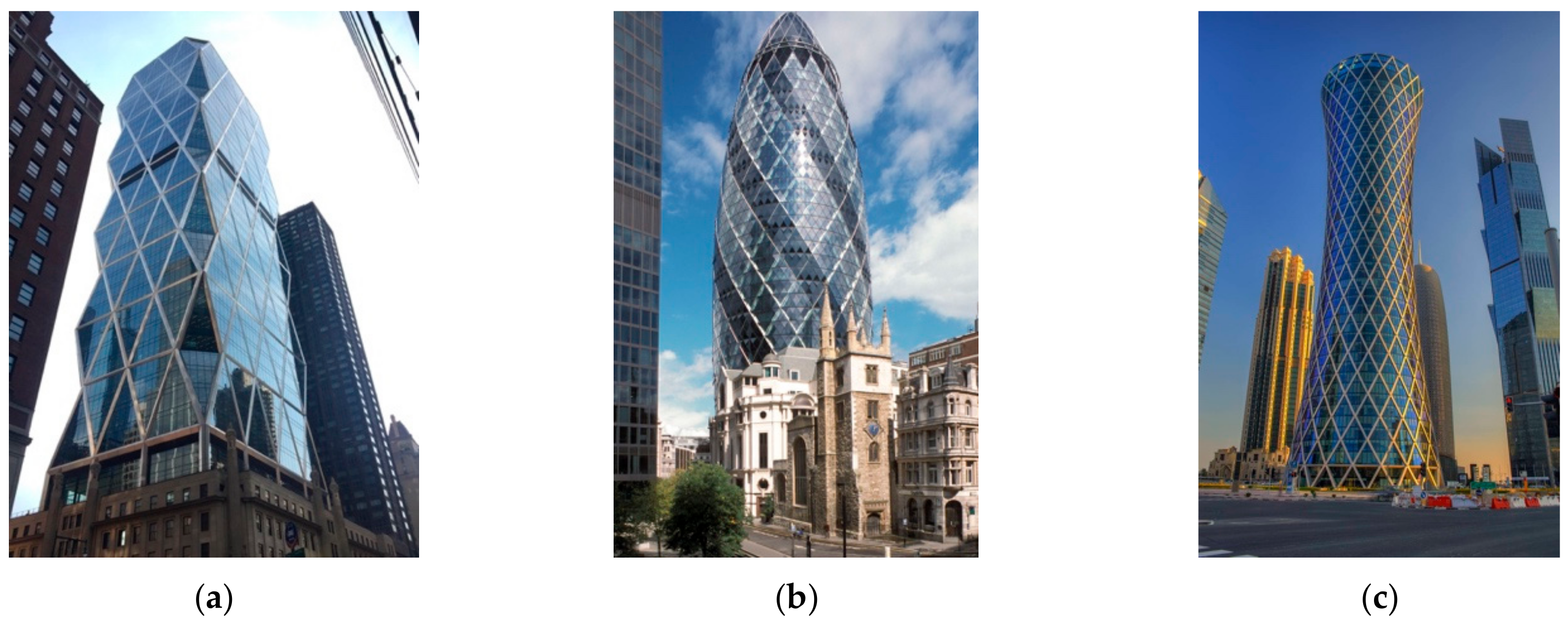
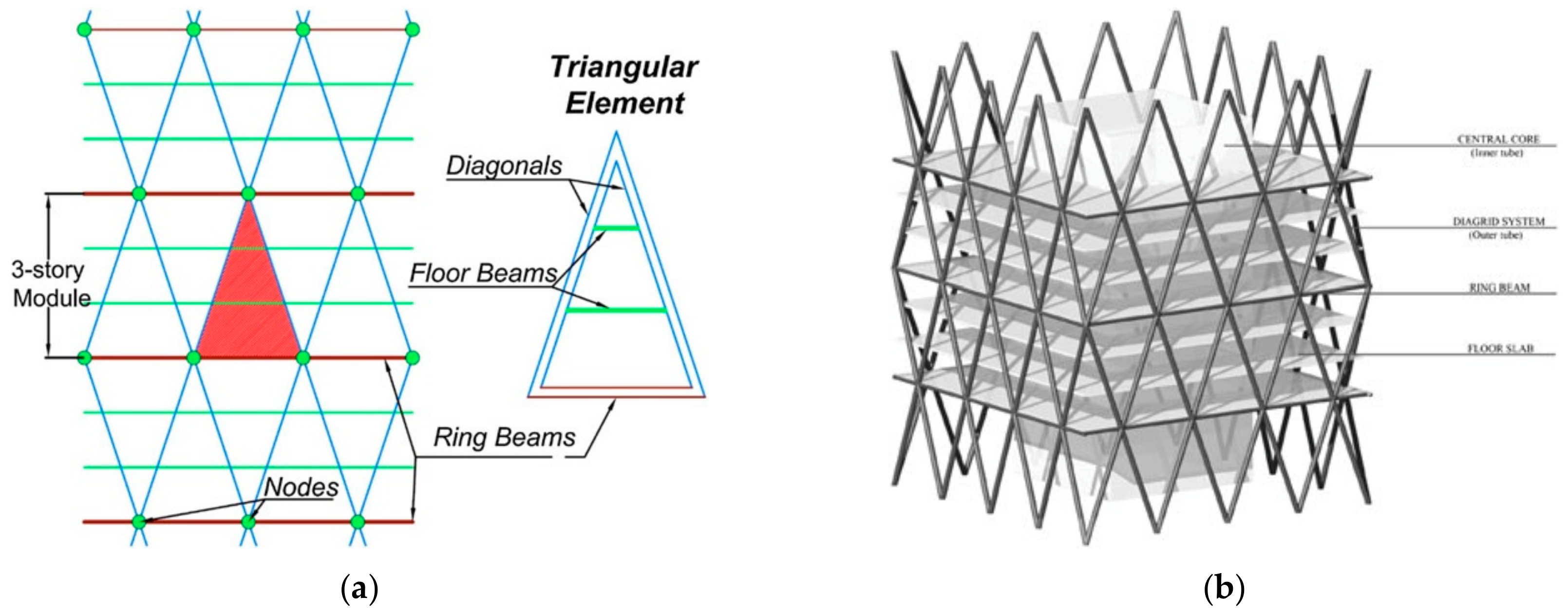
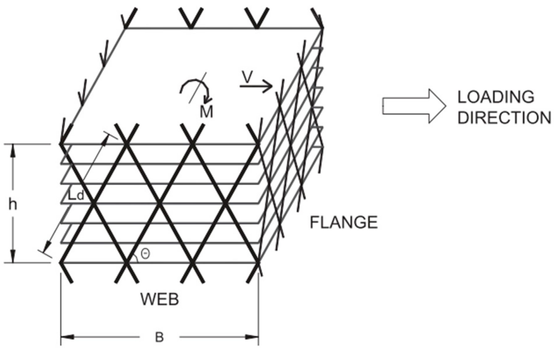
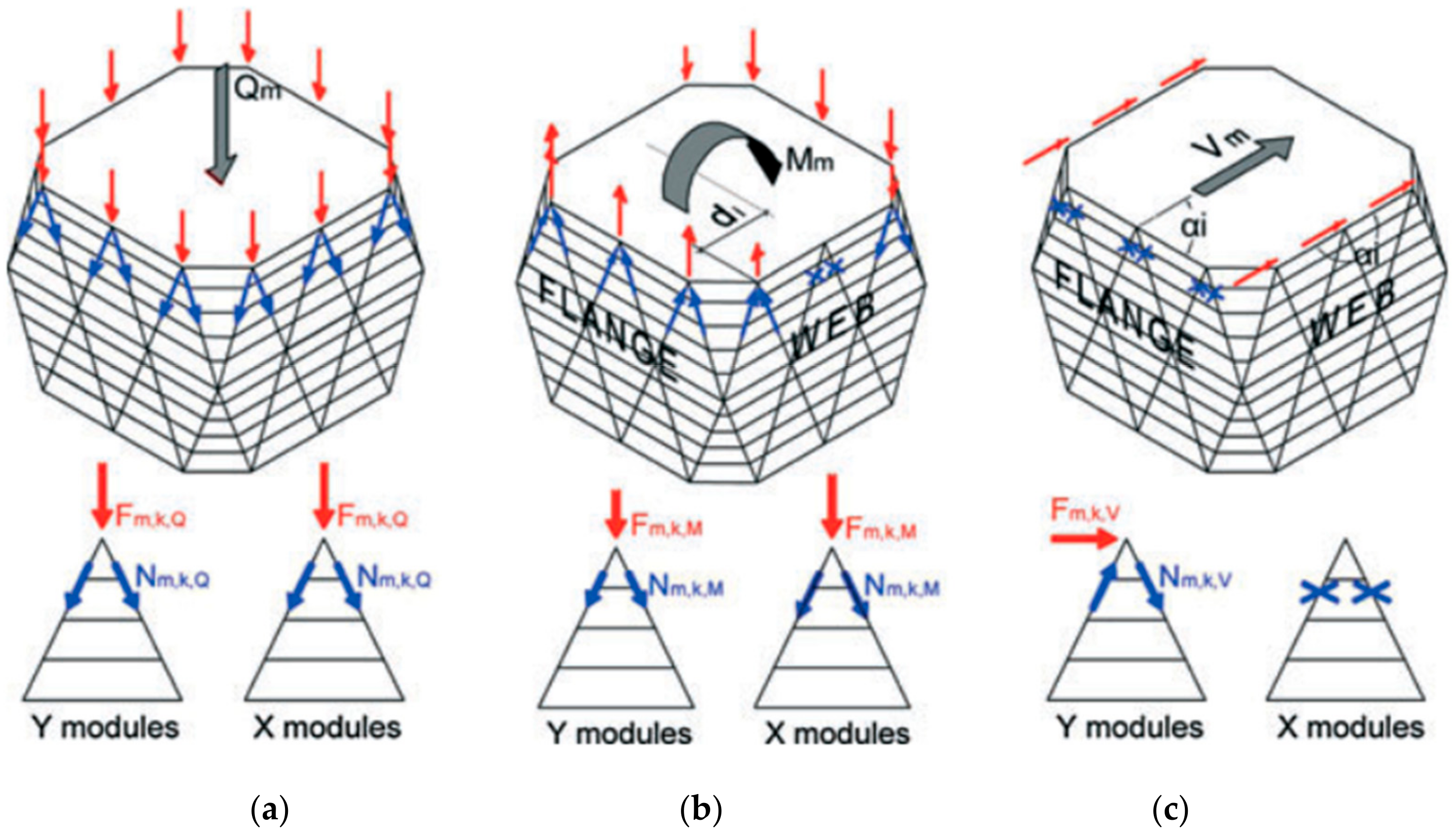
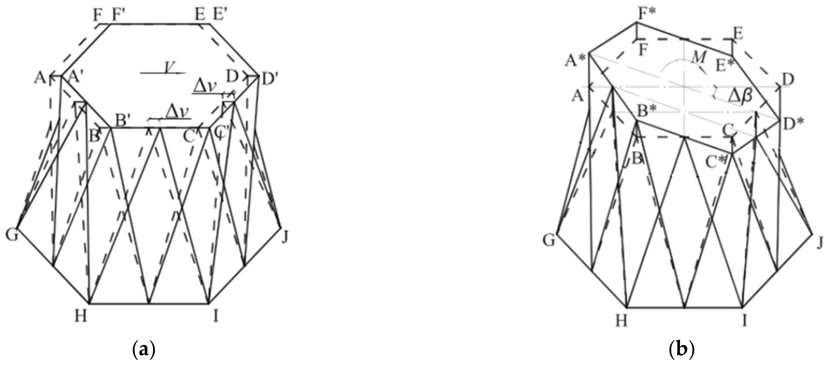
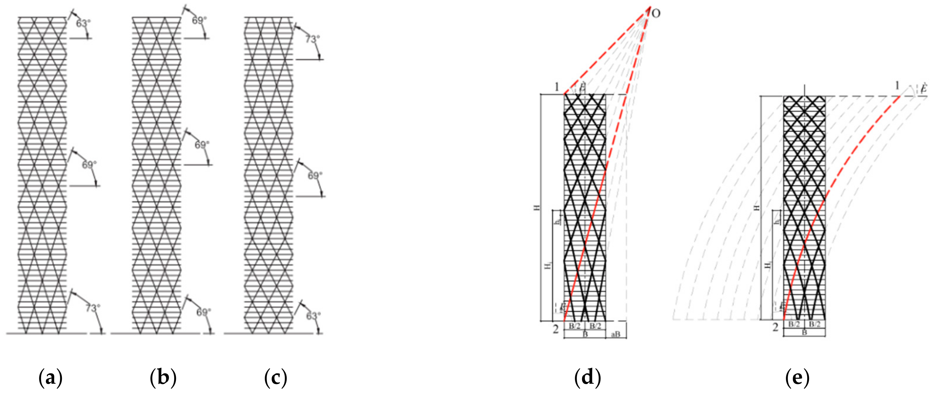
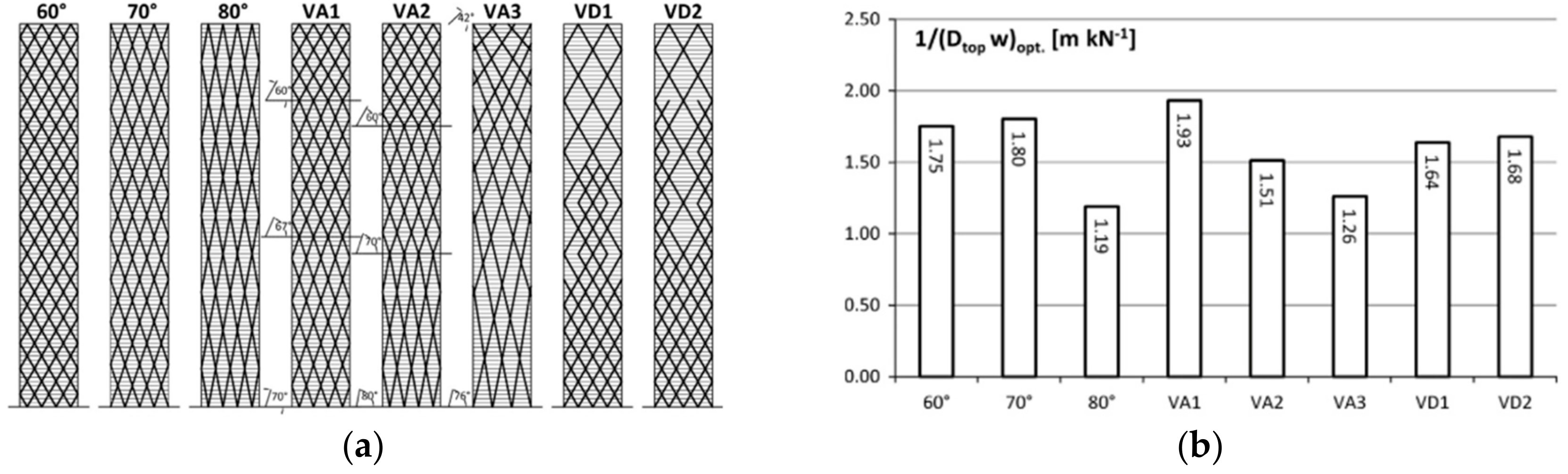
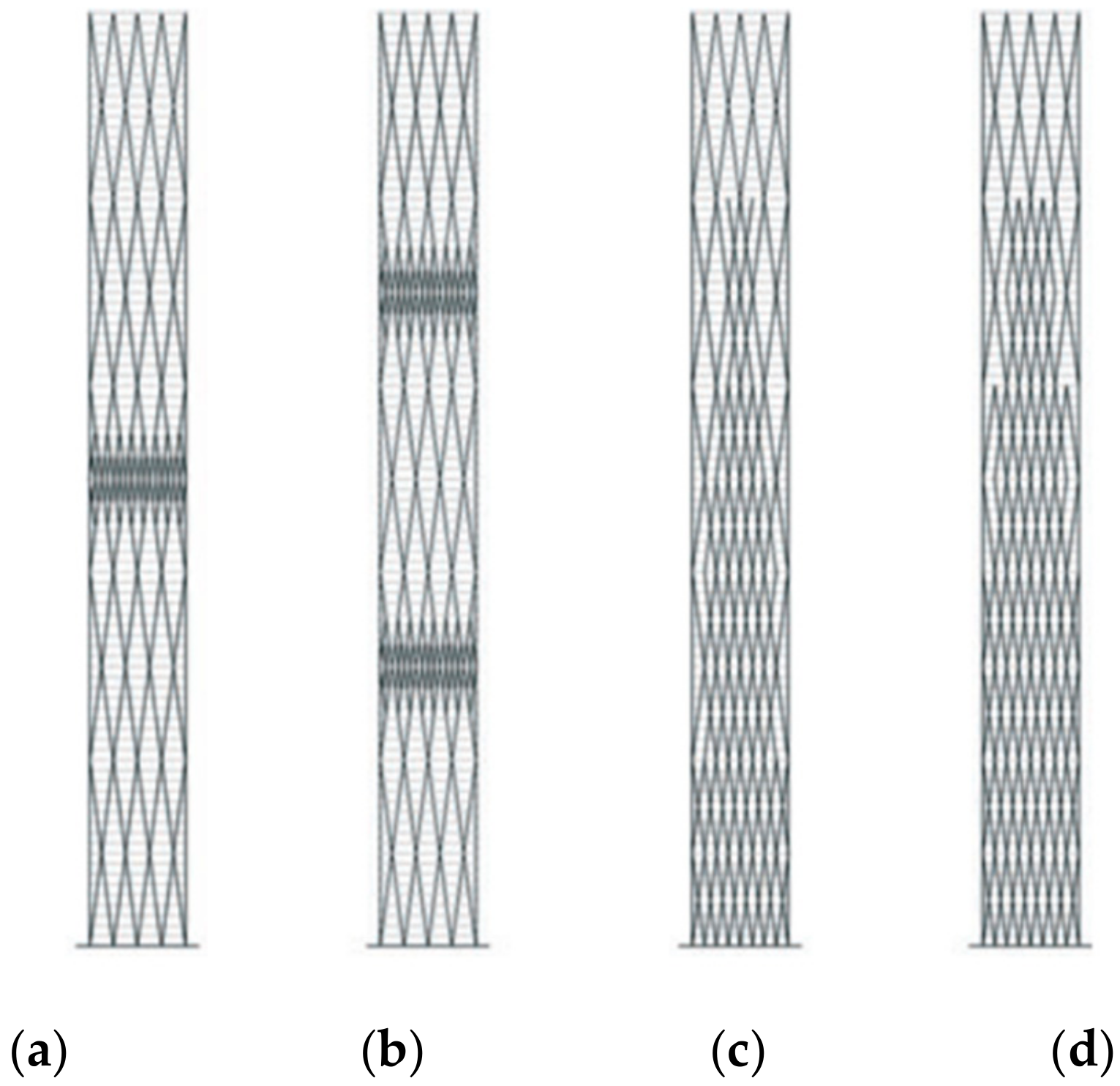
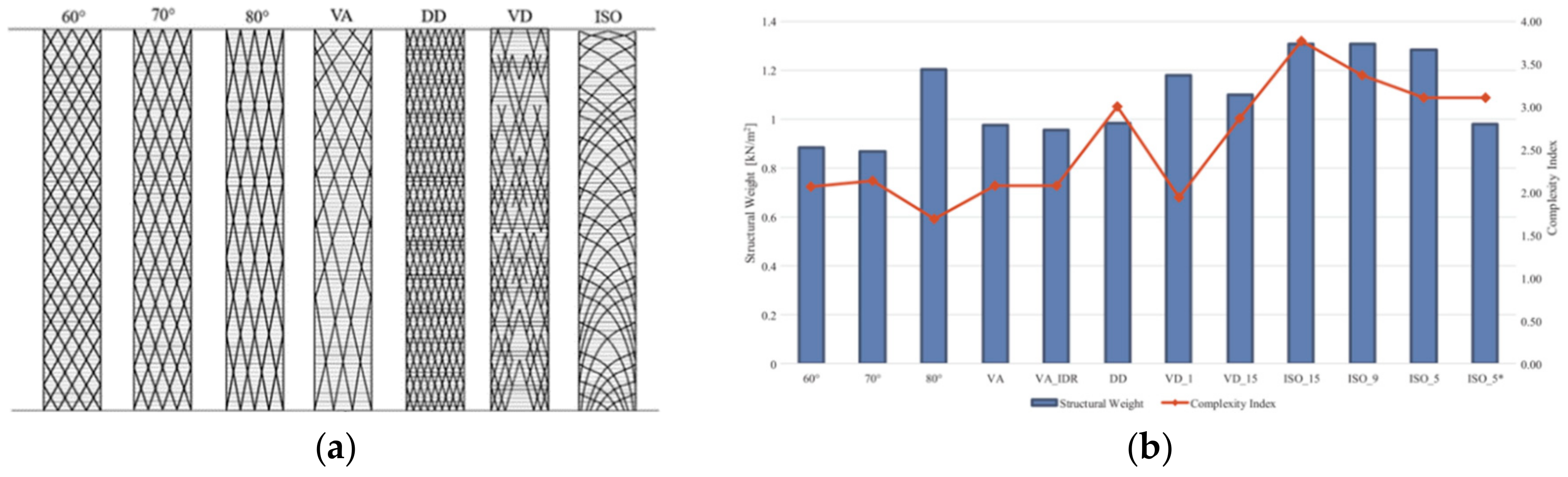
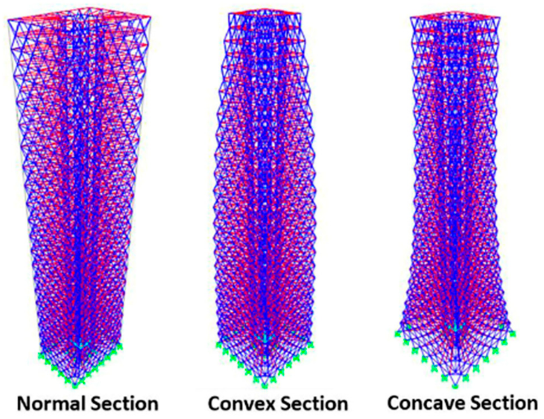
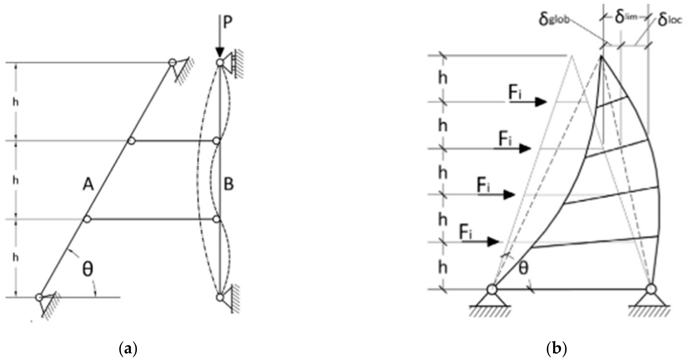
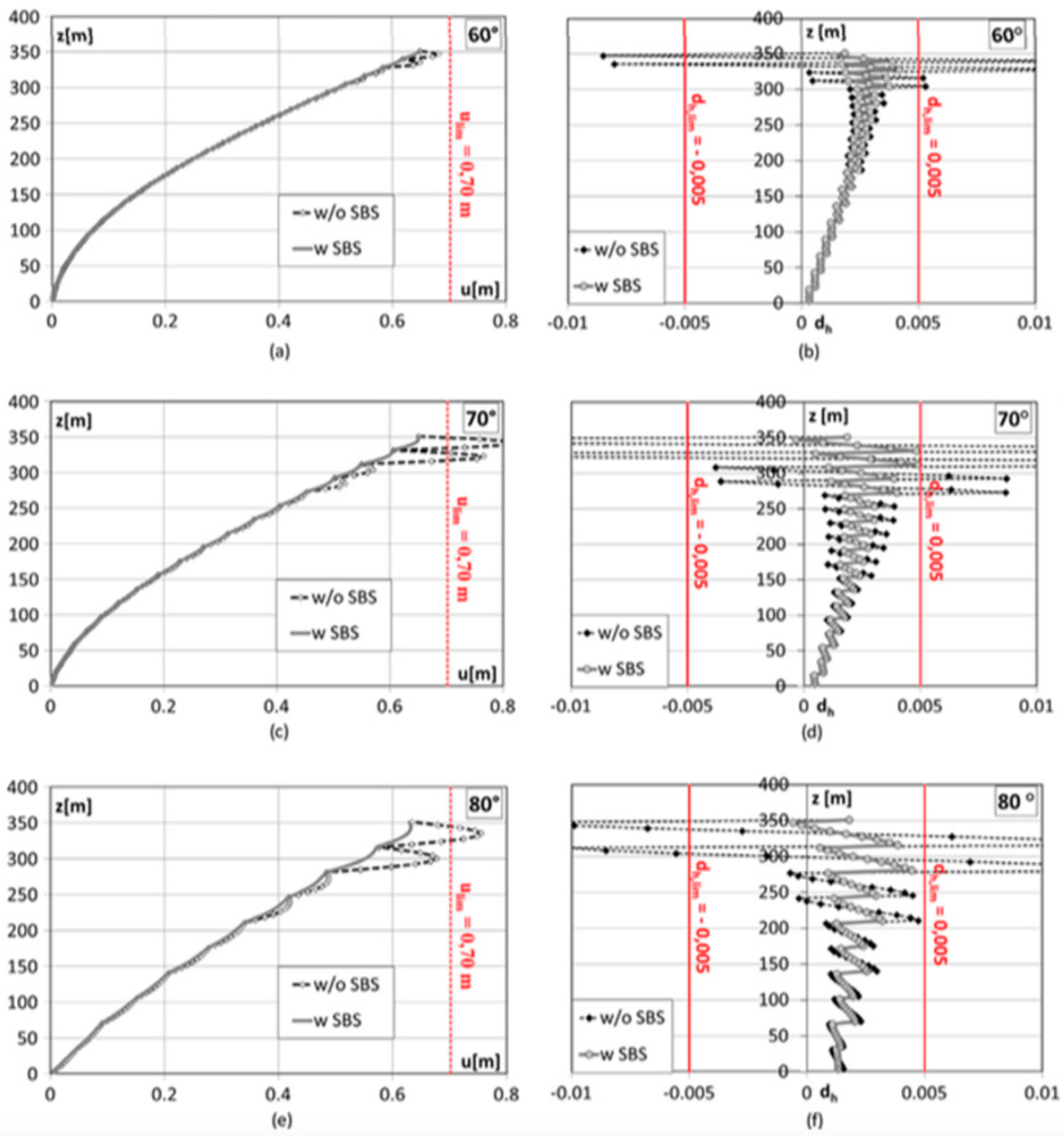
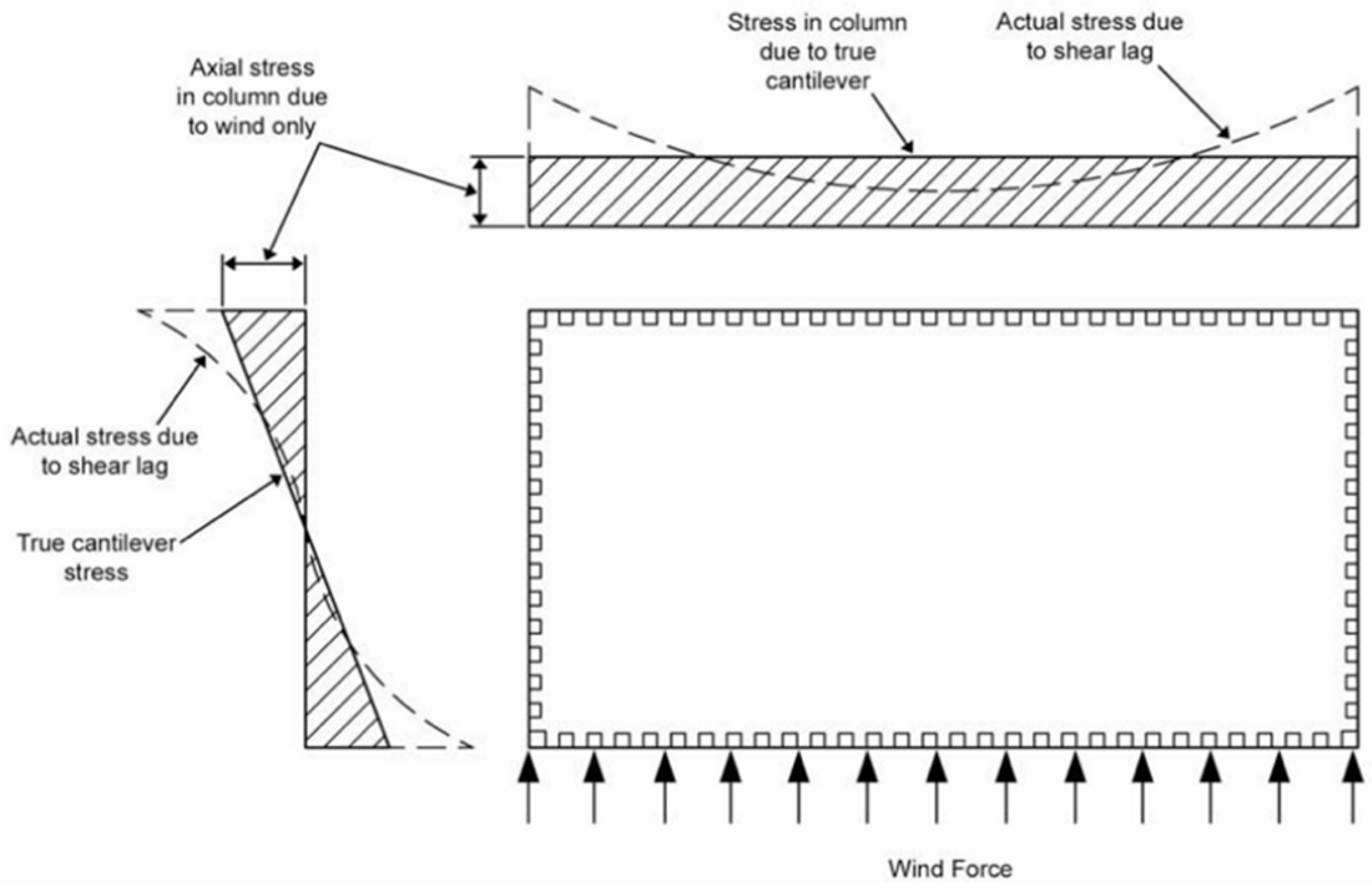
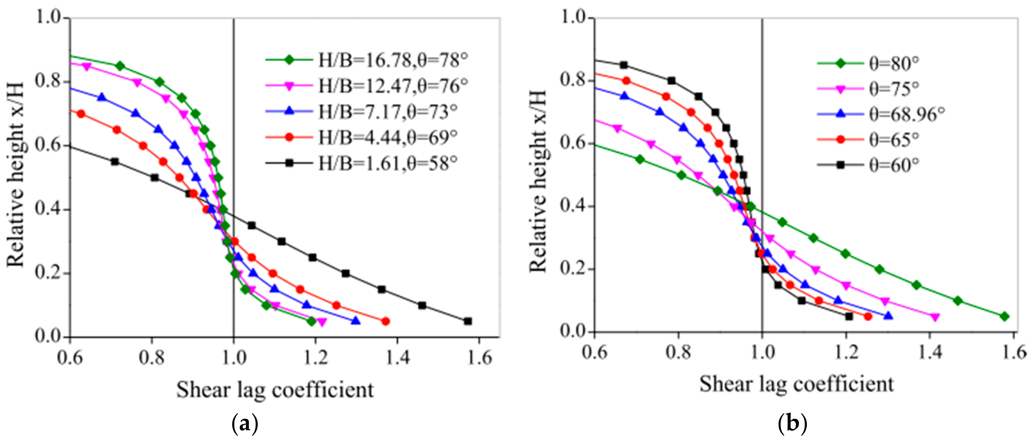
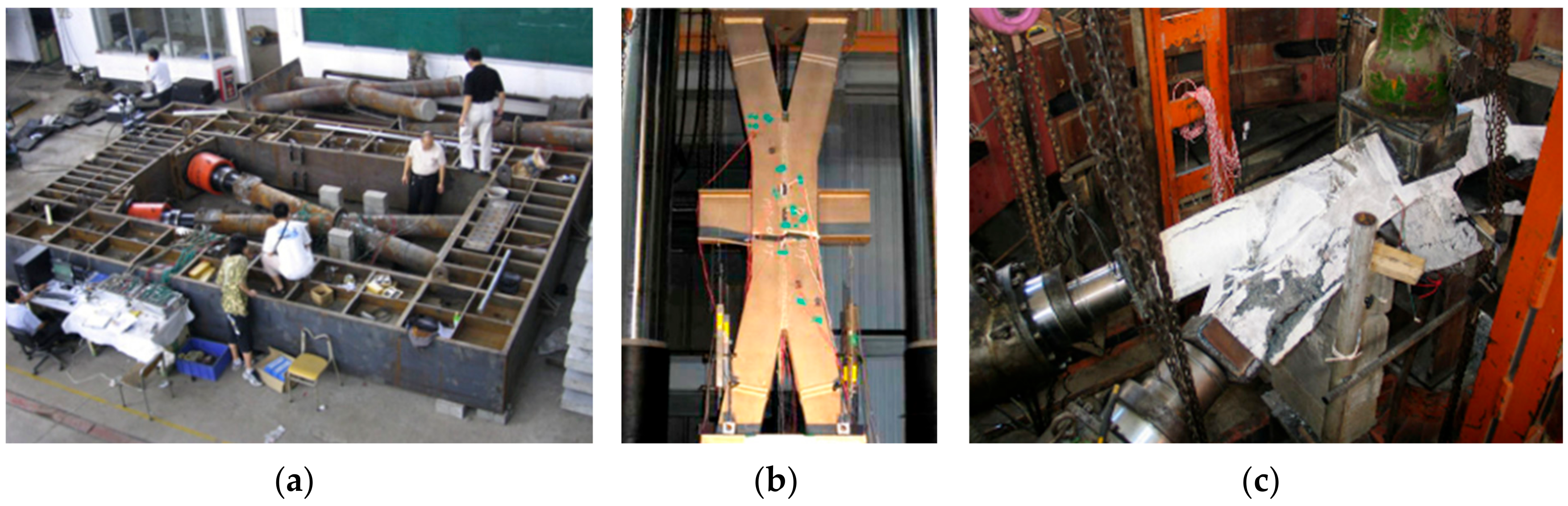
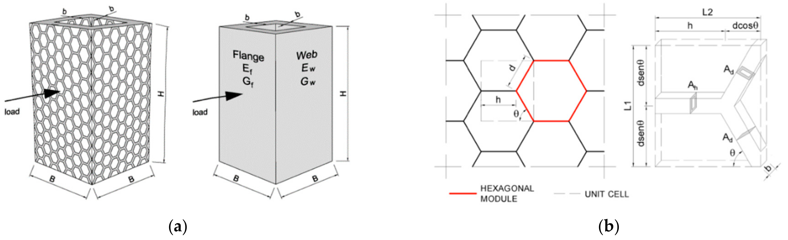
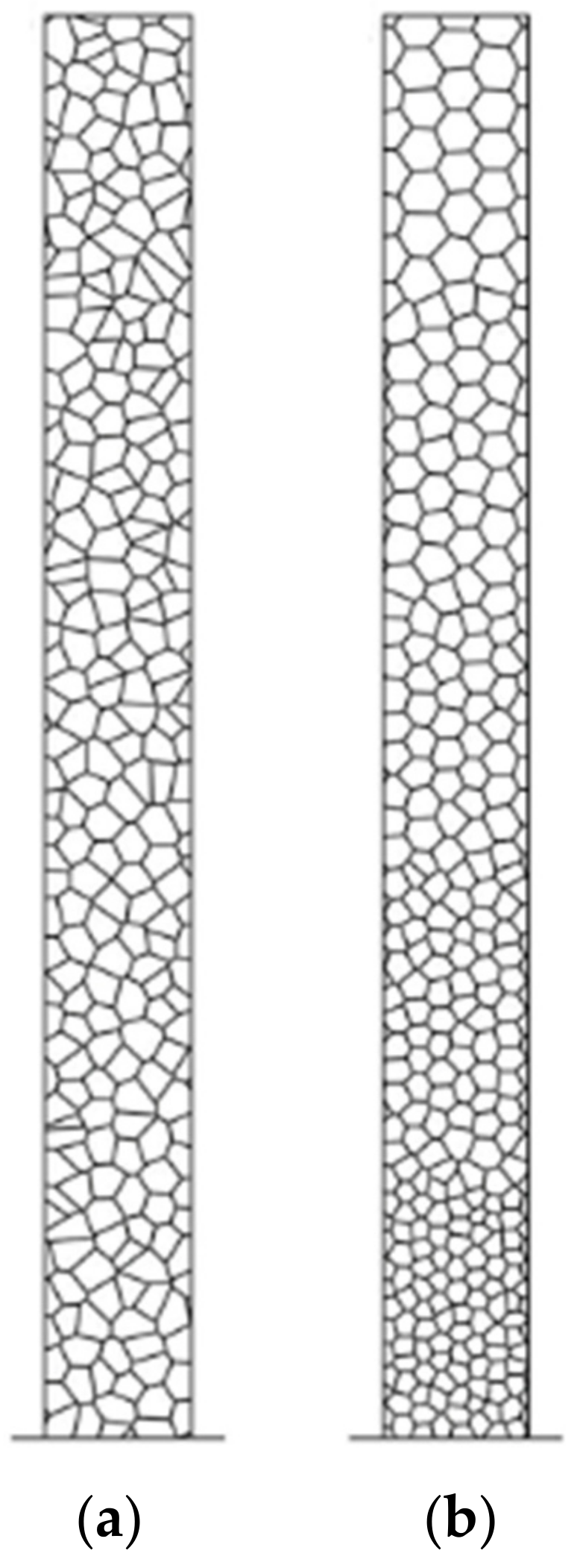


