Article

Application of Modal-Displacement Based Design Method to Multi-Story Timber Blockhaus Structures

1
Department of Civil, Architecture and Building and Environmental Engineering, University of L’Aquila, 67100 L’Aquila, Italy
2
Department of Engineering and Architecture, University of Trieste, 34127 Trieste, Italy
*
Author to whom correspondence should be addressed.
Appl. Sci. 2020, 10(11), 3889; https://doi.org/10.3390/app10113889
Submission received: 31 March 2020 / Revised: 20 May 2020 / Accepted: 2 June 2020 / Published: 3 June 2020

Abstract

:
Structures under seismic excitation undergo different inter-story drift levels that can be associated to damage of both structural and non-structural elements, and thus to the expected losses. The Modal-Displacement Based Design (DBD) procedure, in this regard, has been developed to fix major issues of Force Based Design (FBD) approaches, thus to design multi-story buildings in which the inter-story drift can allow one to control damage mechanisms. In this paper, the conventional Modal-DBD methodology is applied to multi-story timber buildings constructed using the Blockhaus technology. Given their intrinsic geometrical and mechanical features (i.e., stacking of logs, door/window openings, gaps and friction mechanisms, etc.), dedicated methods of analysis are required for them, compared to other wooden structures. A three-story case-study Blockhaus system of technical interest is thus presented for the assessment of Modal-DBD calculation steps. As shown, special care must be spent for the selection of convenient inter-story drift limits that in general should reflect the characteristics of the examined structural typology. The backbone parameters are thus collected for each shear-wall composing the 3D Blockhaus building, based on refined Finite Element (FE) analyses of separate log-walls. The overall results of the Modal-DBD process are thus finally assessed by means of a Push-Over (PO) analysis, carried out on a simplified 3D FE model of the examined multi-story structure. The comparison of FE predictions, as shown, demonstrates that reliable estimates can be obtained when the Modal-DBD procedure is applied to timber Blockhaus systems. In particular, base shear loads can be estimated with good accuracy, while the corresponding top displacements are slightly overestimated (with up to +10%–14% the expected values, for the collapse prevention performance level).

1. Introduction

In the last decades, there has been strong interest worldwide in developing codes for buildings focused on the Performance Based Seismic Design (PBD), rather on prescriptive criteria [1]. As a general rule, the PDB procedure allows designing structures able to satisfy a specific performance level, for a desired seismic hazard [2]. The design philosophy is based on the collapse prevention and the reduction of repairing costs, thus bringing social and economic benefits. The PBD goals can be reached through different design strategies, such as the Force-Based Design (FBD) or the Displacement-Based Design (DBD) calculation processes.
Despite the FBD procedure has been implemented in standards for earthquake-resistant buildings (i.e., the current edition of the International Building Code [3]), however, some of the seismic design provisions in use (see for example the ASCE 41-17 [4] and ASCE 7-16 [5] documents) still do not respect the general PBD strategy, due to several intrinsic issues. For a given building object of analysis, these issues come upon the FBD basic hypothesis, namely the assumption of the initial elastic stiffness and the adoption of a specific force reduction factor to predict the inelastic force distribution. As also discussed in [6], for most of the buildings of technical interest, it is thus not possible to fully exploit the FBD goals (and achieve an optimal design target). It is in fact reasonably expected that two different structures (still being constructed according to the same technology) can exhibit different levels of damage under the same input seismic action. Moreover, according to standards in use, the actual seismic design of structures is carried out with a uniform-hazard spectrum for a fixed return period, hence leading to uncontrolled values of failure probability, which in turn can usually vary with the structural and location features [7].
The DBD procedure, in this regard, is a multi-level design approach based on the displacement response spectrum as a cornerstone for calculating the base shear demand. In most of the cases, the inter-story drift is chosen as a key parameter to control the global level of damage, and its limit values strictly depend on the structural system to verify. Deformations or strains are generally recognized to better assess the damage evolution, given that they are expected to go beyond the elastic range. The DBD procedure follows, as the FBD, the “Capacity Design” principles, i.e., the “Hierarchy of Resistances”, to ensure that plastic hinges occur only at pre-established points. However, the DBD procedure has been basically developed to overcome the FBD limitations, hence allowing achievement of consistent performance levels for structures with different properties, through the definition of uniform-risk design maps [7].
In this paper, the original Modal-DBD calculation steps are further extended from their formulation and adapted to the structural typology of timber Blockhaus (or log-house) systems. They represent one of the oldest construction typologies, being based on overlapped (solid or glu-lam) timber logs that are interconnected by carpentry joints. Based on a multi-story case-study building of technical interest, key issues for the application of the Modal-DBD approach to Blockhaus structures are thus discussed. Major advantage for the overall calculation process, as shown, is derived from refined Finite Element (FE) numerical simulations carried out on single log-wall portions under in-plane lateral loads, so as to collect the key mechanical parameters that are of primary interest for the definition of the required backbone curves. The accuracy of calculation results is then assessed with the support of a Push-Over (PO) analysis of the multi-story case-study building.

2. Application of DBD Procedures to Timber Structures

Several DBD procedures have been developed in the years, for specific purposes. Accordingly, a number of research studies can be found in the literature, for different structural typologies (see for example [8,9,10]).
In the framework of seismic design of timber structures, the most consolidated methods are the Direct-DBD [6] and the Modal-DBD [11,12]. Besides that, in the European scenario, the N2 method [10] is the most widespread procedure in use for seismic evaluations, given that it is currently the only one implemented in design standards [13]. DBD procedures for timber structures are generally uncommon for practical engineers, meanwhile in the research community, N2 method [10] is the most widespread used for seismic evaluations. N2 method is a powerful tool in case of assessment of the structural capacity of existing structures or designed models. On the other hand, Direct-DBD [6] and the Modal-DBD [11,12] are the best way for the design process. In particular, the last one, has the advantage to be applicable for structures in which the first vibration mode does not invoke a considerable amount of mass and it is able to combine all modes for the evaluation of the base shear demand. For this advantage, the Modal-DBD could represent an optimal way to design various structural typologies as timber buildings.

2.1. Direct-DBD Method

The so-called Direct Displacement Based Design (D-DBD) method requires a minimum iterative calculation process, for the optimal design of multi-story buildings and structures. For a given input earthquake, buildings must basically respond with a specific limit displacement (given by design codes) that corresponds to an acceptable limit state [6].
The method is based on the use of the secant stiffness Ke to maximum displacement Δd, based on a “Substitute Structure” [6]. Another key parameter is the viscous damping ξ of the equivalent Single-Degree Of Freedom (SDOF) for the examined structure. The latter accounts for both the elastic damping and the hysteretic energy absorbed during inelastic response, thus implicitly includes the material properties and structural type, for a given level of ductility demand [6]. Major issues and uncertainties for design are however related to the definition of the substitute structure parameters.

2.2. N2-DBD Method

The N2-DBD method was first proposed in [10] by Fajfar and Gaspersic for Reinforced Concrete (RC) structures, and has been successively incorporated into Annex-B of EC8 [13,14]. The model is suitable for the evaluation of the seismic behavior of existing or new realization buildings, as far as the fundamental vibration mode is predominant in their dynamic response. The N2-name itself summarizes the basic features of the method: “2” because it is based on the use of two separate mathematical models, and “N” because accounting for the application of the response spectrum approach and of the non-linear static analysis. Another fundamental hypothesis is then related to the choice of a cumulative damage model, see [10].

3. Modal-DBD Method

The Modal-DBD method was proposed by Pang and Rosowsky [11,12] for the design of multi-story light-frame wood buildings, within the framework of the past NEESWood Project.

3.1. General Procedure

The procedure was originally developed in [11,12] for multi-story wood-frame structures, and consists in performing a normalized modal analysis that allows one to define the displacement capacity for a given building. A key role for design is assigned to backbone load–displacement curves for each wooden panel (to estimate the base shear Fb(δ) and the equivalent stiffness Kel), as well as to interstory drift limits for each performance level (i.e., Immediate Occupancy (IO), Life Safety (LS) and Collapse Prevention (CP)). The latter values represent in fact the displacement capacity and demand of the building object of analysis, and they must be preliminary fixed, at the beginning of the calculation process. The basic assumption of the approach, see [11,12], is that the stiffness of each wooden panel is proportional to the relative length.
The general steps for the multi-story Modal-DBD procedure are thus summarized in Figure 1, and namely require to [11,12]:
(1)
Define multiple performance levels, in terms of inter-story drift limits for a given set of seismic hazard levels;
(2)
Calculate the mass and stiffness ratios (relative to the first floor) for each story level;
(3)
Perform a normalized modal analysis on the equivalent linear Multiple-Degrees Of Freedom (MDOF) system, in order to obtain the corresponding inter-story drift factors and natural frequency parameters;
(4)
Define a set of inter-story drift spectra and determine (for the most severe hazard level) the equivalent stiffness required at each floor;
(5)
Select the most suitable lateral force resisting system, from available wood shear-wall design tables. These include information on shear-wall backbone response and equivalent stiffness, at various drift levels;
(6)
Check the overall design process, using the actual stiffness ratios (based on step 5). Revise the shear-wall selection and detailing, if needed;
(7)
Repeat steps 2-to-6 for each performance level, using the actual stiffness ratios of the selected shear-walls. Revise the design, in the case the drift limits are exceeded at any performance level;
(8)
Finally, compute the design base shear, story shear and uplift force, based on the actual non-linear backbone curve of each shear-wall.
As known, the effect of torsional response contributions for irregular (non-symmetric) structures is not accounted in the method from Pang and Rosowsky [11,12]. Accordingly, the latter aspect is disregarded also in this research study, for the geometrical features of the selected case-study system (Section 4). As far as the lateral load resisting elements are not placed symmetrically in a given structure, however, it is also generally recognized that the story-levels would experience a certain displacement (or inter-story drift) due to torsional phenomena. Accordingly, the recommendations reported in [15], where torsion-related issues in displacement-based design methods have been addressed for irregular buildings, should be taken into account.

3.2. Modal-DBD Method Applied to Light-Frame Wooden Systems

As a case-study example for the application of the original Modal-DBD method, Pang and Rosowsky took into account in [11] a three-story light-frame building with geometrical and mechanical features in close correlation with the two-story benchmark structure of the CUREE-Caltech Woodframe project [16]. The analyses were performed placing the structure near the City Hall in Los Angeles (CA, USA), and accounting for the FEMA 356 provisions [17].
The procedure was based on a series of design tables inclusive of shear-wall backbone parameters, properly calibrated to represent walls having different types of connectors, nailing patterns and widths. In addition to shear-wall test data, the CASHEW program outcome was also used to generate and calibrate these design tables, see [11]. The Modal-DBD procedure was verified using non-linear MDOF Dynamic analyses. The three-story building was modeled using the SAWS (Seismic Analysis of Wood Structures) program; each shear-wall segment was modeled as a non-linear system using the hysteretic model in the CASHEW program. The Modal-DBD design procedure was validating by comparing the expected drift level of the designed structure to the actual mean drift profile obtained from the dynamic time-history analyses. The difference of average peak drifts of the controlling floors evaluated for the X-direction of the structure for the CP, LS and IO hazard level from the time-history analyses and from Modal-DBD method, is −3.78%, 0.71% and 13.04% respectively.

3.3. Modal-DBD Method Applied to CLT Systems

Following [11], the Modal-DBD method was first extended and adapted by Bolvardi et al. [18] for an isolated, twelve-story Cross-Laminated Timber (CLT) building in Los Angeles (CA, USA). The fundamental assumption was that the non-linear displacement and energy dissipation was mostly expected to occur in the isolation system. Accordingly—due to the presence of a single isolation layer—the multi-story isolated building was simplified into an equivalent 3-DOF system inclusive of (i) an equivalent segment below the isolation, (ii) the isolation layer itself and (iii) an equivalent segment in the top, being representative of the elevation structure. For each CLT story, a monotonic Push-Over analysis was thus separately performed, to identify the equivalent linear stiffness, mass and height. The validity and reliability of the overall process was finally verified by measuring the performance of the building through non-linear dynamic analyses. As a major outcome of the study reported in [18], it was shown that the proposed methodology is reliable and efficient for controlling the deformation of both the isolation layer and CLT multi-story buildings. The comparison of numerical analysis results with the above defined drift/displacement limits were met for all the hazard levels, with the required non-exceedance probability.

3.4. Modal-DBD Method Applied to Blockhaus Systems

In this paper, the modal-DBD method is first adapted and assessed towards the application for the structural typology of multi-story timber Blockhaus systems.

3.4.1. Basic Features of Blockhaus Systems

Traditional Blockhaus systems are well-known to result from the assembly of shear-walls (having both partition and load-bearing features) that are obtained by stacking and intercepting multiple timber logs. These logs, and the so-assembled shear log-walls, have a key role in resisting the lateral forces of a given structure, with typical layout configurations that can include residential or commercial buildings with up to 2-(or 3) story levels.
In the last years, several authors carried out extensive studies to assess the seismic performance of such a relatively ancient but widely used structural solution, including monotonic Push-Over and cyclic tests on corner joint specimens (i.e., Figure 2a), or full-size log-walls under lateral in-plane loads (see for example Figure 2b and [19,20,21]), and up to 3D building prototypes under shake-table tests [22,23,24].
According to the literature, it was generally proved that friction phenomena, mounting tolerance gaps and corner joints are the main influencing parameters for the in-plane, non-linear response of the typical timber log-walls. In particular, it is generally recognized that:
  • Due to friction phenomena, timber log-walls can offer a certain amount of energy dissipation;
  • The amount of vertical compressive loads (i.e., due to permanent and accidental loads for each log-wall belonging to a full 3D building) define the amplitude of the hysteretic cycle;
  • The local crushing of timber logs (i.e., due to compression perpendicular to the grain, as it is in the region of intercepting log-walls and corner joints) leads to a partial stiffness degradation for medium-high displacement cycles.
The above key mechanisms generally manifest in a cyclic behavior for log-walls under in-plane lateral loads that is characterized by pinching, stiffness and strength degradations that should be properly taken into account for design purposes. To this aim, two different hysteretic models have been proposed in [19] and [21], being both developed on the base of a log-wall stiffness calculation that directly depends on the geometrical characteristics of the corner joints in use.

3.4.2. Preliminary Assessment of the Modal-DBD Assumptions and Requisites for Blockhaus Log-Walls

As emphasized in Section 3.1, the basic assumption of the Modal-DBD approach for a given case-study Blockhaus building, is that the in-plane stiffness of each shear-wall could be assumed as proportional to the wall length [11]. At the preliminary stage of the Modal-DBD extension to Blockhaus systems, accordingly, it was hence verified the validity of this mandatory requisite.
Such a consideration can be essentially based on the refined FE numerical models of single carpentry joints that have been reported in [25], by accounting for the compression resistance limits of timber logs in use (i.e., for all the contact regions of corner joints in which crushing can occur). The mentioned FE approach proved in fact to offer an excellent correlation between joint stiffness estimated from literature experiments or by the corresponding FE approaches.
As far as the in-plane lateral stiffness of a single log-wall is taken into account, it is then convenient to refer to the schematic representation in Figure 3, where the mechanical behavior is schematized for a single log-wall under in-plane lateral loads and vertical compressive pressures.
Let us assume that the typical L × H log-wall is thus obtained by the superposition of n timber members that are in contact along their top-bottom surfaces, and a sill log joined at the foundation level. For calculation purposes, the foundation restraints (typically consisting in regularly spaced steel angular brackets) can be assumed as indefinitely rigid, for the base log of each shear-wall. The main logs are then pre-compressed by a uniformly distributed load p and subjected to an in-plane lateral load F. Under the so-imposed design loads, the expected top lateral displacement is given by the sum of sequential relative displacements of n overlapping logs, as well as by the possible local deformation (i.e., initial crushing of timber logs, in the region of corner notches, etc.) that can manifest in further flexibility of the system. The analytical model of Figure 3, in particular, assumes that [25]:
  • The corner joints are represented in the form of a series of linear elastic springs, with equivalent stiffness Kel. The latter (when experiments are not available) can be estimated by means of detailed FE models of corner joints;
  • The presence of n tolerance gaps is taken into account in the region of corner joints (with tgap their average amplitude in the range from 0.5 to 1 mm), as an additional contribution for the total displacement estimation;
  • Static friction effects are accounted in the form of f-Coulomb forces;
  • Finally, the carpentry joints are considered at the logs ends only (i.e., possible internal joints and restraints are fully disregarded).
The force equilibrium condition for the system in Figure 3 requires that:
F = f + 2 K e l d i
where the friction contribution is given by:
f = µ p L
with μ the static friction coefficient.
From Equation (1), it follows that the in-plane lateral force F can be also rewritten as:
F = K t o t d t o p = f + 2 K e l δ d i = µ p L + 2 K e l d i
where di represents the displacement of the i-th log (with I = 2,...n) and dtop the displacement at the top level of the wall:
d t o p = n t g a p + i = 2 n d i
For a given amplitude of distributed pre-compressive vertical load p and a certain configuration for the corner joints in use (thus corresponding to a specific stiffness Kel), the required proportionality between the shear-wall stiffness and the wall length L is thus confirmed, that is:
K t o t = µ p d t o p L + 2 K e l d i d t o p

4. Case-Study Building

4.1. Geometrical and Mechanical Properties

The three-story Blockhaus building schematized in Figure 4 was taken into account in this paper, as an illustrative design example. The system has plan dimensions of 5.64 m × 7.3 m, with opening details according to Figure 4a,b for the ground floor and upper levels respectively. The elevation views are also shown in Figure 4c–f, with ground/first floors having both a nominal height of 2.72 m.
The building layout was defined by taking inspiration from the past Rusticasa 3D prototype that was experimentally investigated in [23] and then numerically analyzed in [24]. Compared to the past research project, however, the major difference of the current investigation is represented by the presence of one additional story in the top. The total height of the building, accordingly, is in the order of 6.88 m at the edge to 8.00 m at the ridge, forming a duo-pitch (gable) roof.
In terms of door/window openings, the plan of the structure is symmetrical in the longitudinal X-direction (walls P2 and P4) and asymmetrical in the transverse Y-direction (walls P1 and P2).
The timber logs in use for the walls (see also [23,24]) are shaped with small tongues and grooves both at the top and bottom surfaces. The outer log’s cross-sectional dimensions are assumed in 160 mm × 160 mm (four 40 mm lamellas) while the inner logs have dimension 80 mm × 160 mm (two 40 mm lamellas). All the log ends are then notched to facilitate the intersection of the orthogonal walls, and thus to realize an efficient mechanical connection between the load-bearing components of the 3D assembly. For the corner joints, the presence of construction gaps is also accounted (with tgap = 1 mm).
All the wooden members, finally, are made of glu-lam timber derived from Scots Pine trees (Pinus sylvestris L.) and belonging to a C24 resistance class. For design calculation purposes (given the lack of a more detailed material characterization), the nominal mechanical properties in Table 1 were taken into account.
At the level of each intermediate story, in-plane rigid diaphragms are taken into account. The floor beams have nominal cross-section of 90 mm × 165 mm, and are then superimposed by Oriented Strand Board (OSB) studded panels, which are 22 mm thick.

4.2. Modal-DBD Design Steps

Given that torsional effects are reasonably negligible for the seismic analysis of structures with a mostly symmetric and regular shape—as in the case of the case-study Blockhaus system of Figure 4—the building was analyzed separately along the two principal (X, Y) directions. When required, the procedure steps recalled in Section 3 were adapted from their general definition.

4.2.1. Definition of the Target Performance Level

The first step of Modal-DBD method requires one to define the displacement limits for different hazard levels. For each displacement level, literature values of Non-Exceedance (NE) probability are generally taken into account for the design of ordinary buildings. The ASCE/SEI-7 [5] provisions, for example, require that the displacement targets of Table 2 are satisfied for “other than masonry” structures.
As far as these general modal-DBD rules are taken into account and extended to wooden buildings, a first design issue must be properly assessed for Blockhaus systems. Currently, no specific drift limits are recommended by standards in use for timber structures, in particular regarding the detection of “damage” and the quantification of inter-story drift levels at collapse.
For light-frame buildings, for example, Bolvaldi et al. [18] conveniently adjusted the limits suggested in Table 2 for “other than masonry” systems. Later on, Pei et al. [26] concluded that laterally braced wooden shear-walls could remain stable up to 7%–10% inter-story drift values, depending on the magnitude of the vertical compressive loading. Even different drift limits were adopted by the NEESWood [27] project team. There, a fixed 4% inter-story drift was recognized as an acceptable threshold for Maximum Credible Earthquake (MCE) hazard, while a conventional 7% drift was taken into account for collapse prevention against near fault ground motions.
For the case-study system examined in this paper, based on the evidences of past experiments available in the literature for Blockhaus structures, it is clear that the “other than masonry” drift limits presented in Table 2 would result in extremely conservative design assumptions. The intrinsic flexibility of the examined log-assemblies (as also demonstrated in [20,21]) was thus taken into account for the selection of key parameters of the Modal-DBD analysis.
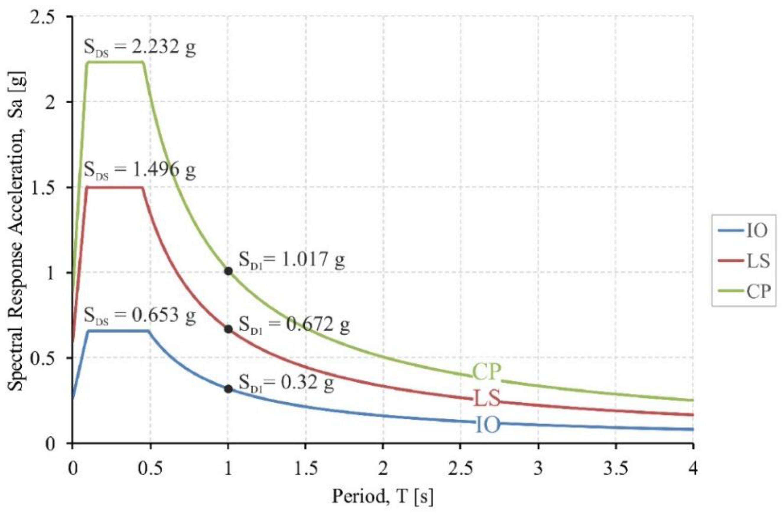
Regarding the Immediate Occupancy level, more in detail, the inter-story drift limitation suggested by EC8 for buildings having ductile non-structural elements was taken into account (see § 4.4.3.2(b) in [13]), thus corresponding to 0.75%. For the Life Safety level, the 2.5% limit suggested in §12 of ASCE 7-16 [
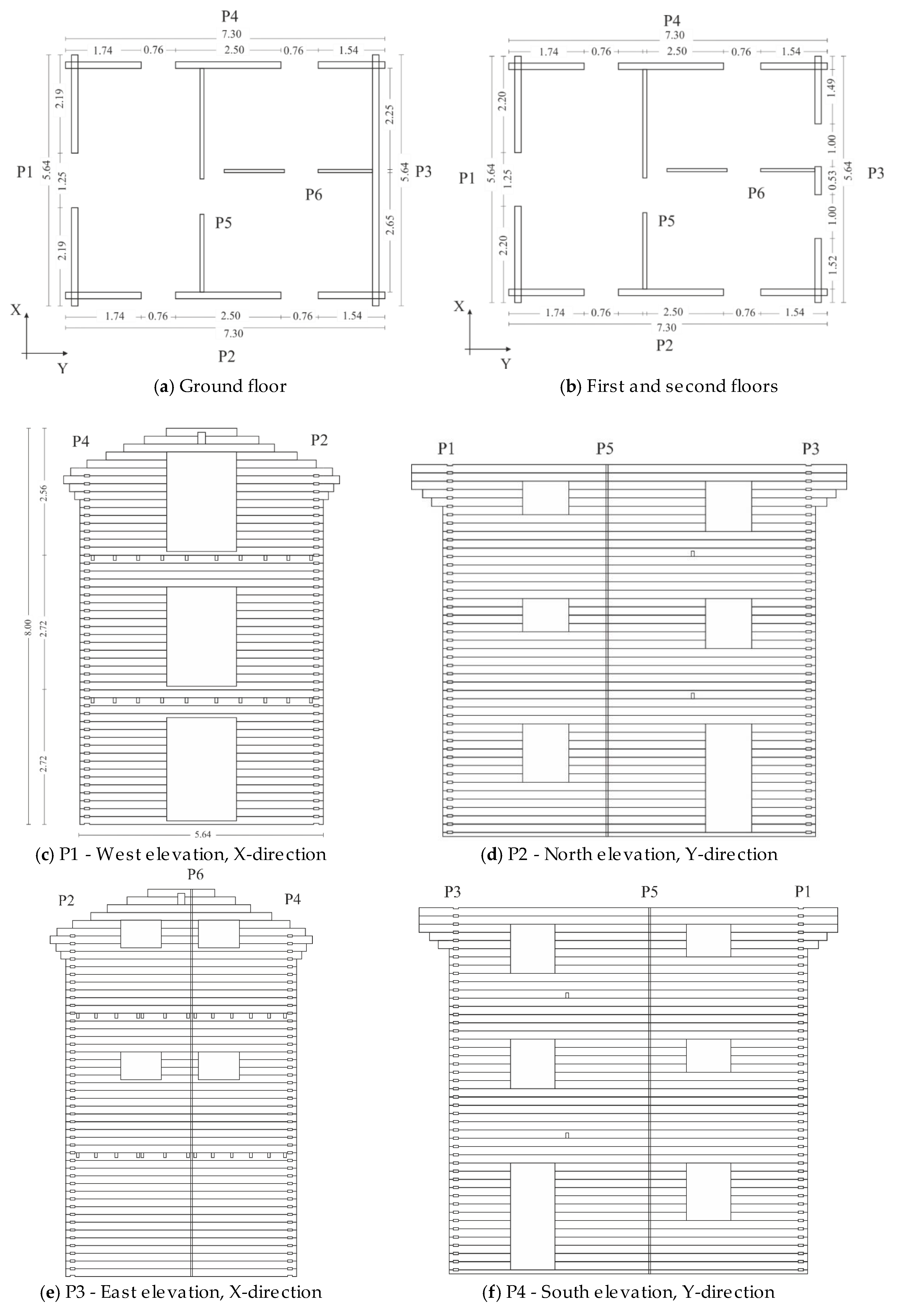
5] was considered. The latter applies to “other than masonry” structures, with four of less stories and a risk category I or II that properly represent the system of Figure 4. Risk category I contains structures that are mainly unoccupied and would result in negligible risk for people, in the case of failure. At the same time, risk category II refers to buildings and structures not specifically classified as conforming to other categories such as the majority of structures (residential, commercial and industrial buildings).
Based on literature values of collapse displacements for Blockhouse structures, finally, experimental and numerical outcomes from past literature projects on single log-walls under in-plane lateral loads were taken into account (i.e., [24]). Accordingly, the conventional 3% drift in use for the CP level was incremented to a more realistic 4%. It was in fact demonstrated by the experimental evidences in [20] that typical log-walls under in-plane seismic loads can accommodate large drift ratios (up to 2%) before local damage in carpentry joints and logs could manifest.

4.2.2. Site and Seismic Parameters

For seismic design purposes, the examined Blockhaus building is assumed to take place in Eureka (CA, USA; Lat. 40.79, Long. -124.16). The reference foundation soil falls within a “Site Class C” (i.e., very dense soil and soft rock), based on [5]. Such an assumption turns out in the design response spectrum curves proposed in Figure 5, as derived from §11 ASCE 7-16 [5]. Input seismic parameters are thus defined in accordance with Section 11.4.4 of [5] and from U.S. Geological Survey (USGS, [28]).

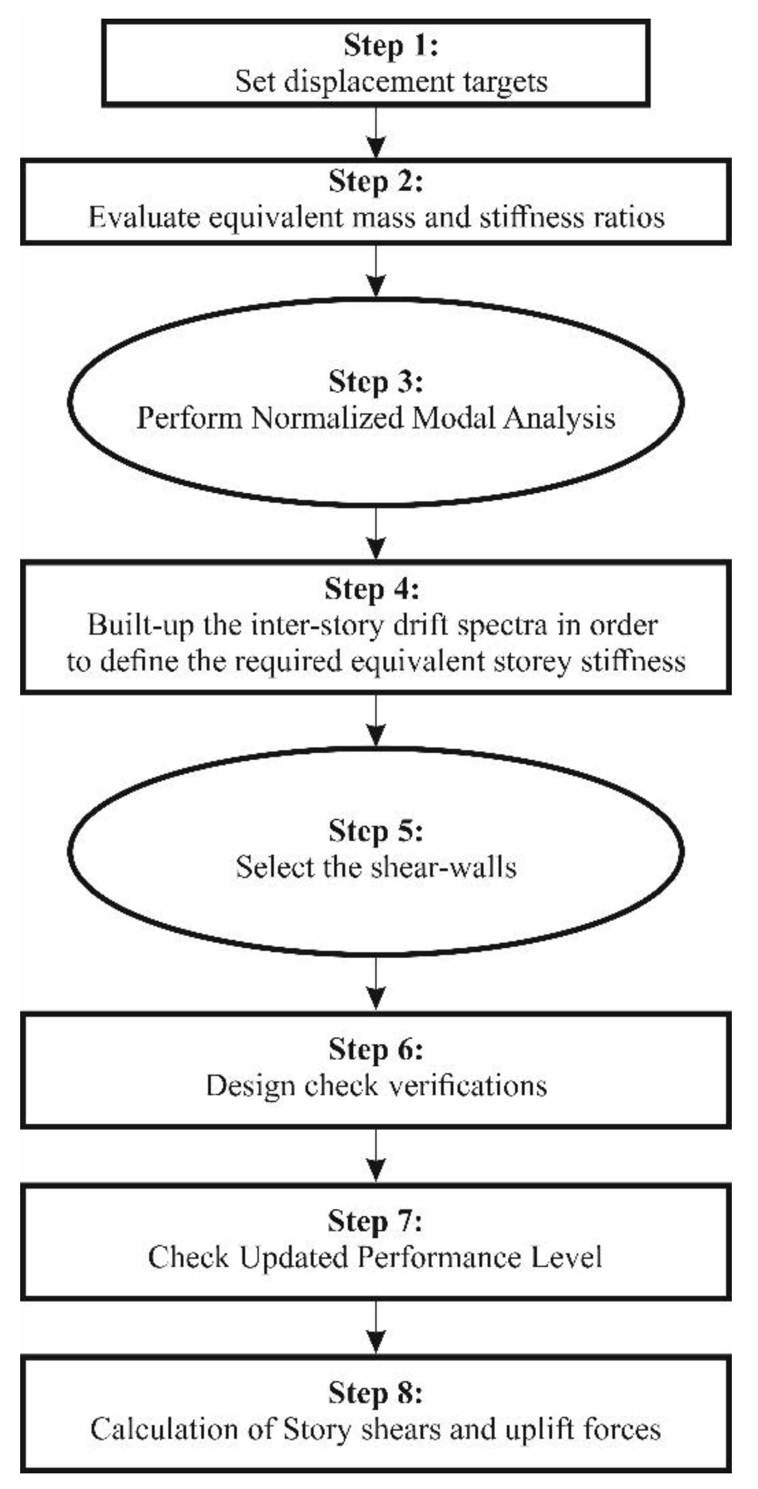
4.2.3. Definition of Equivalent Mass and Stiffness Matrices

Through the analysis steps, the calculation procedure presented in [11,12] was taken into account and applied to the Blockhaus system schematized in Figure 4 (see also Section 4.2.4, Section 4.2.5 and Section 4.2.6). As known, see [11,12], the conventional modal-DBD procedure consists in the equivalent linearization of the reference non-linear MDOF system object of analysis, based on a reliable values for the story stiffness of a linear elastic MDOF. The latter must be estimated at the target inter-story drift, thus is expected to be strictly related the intrinsic features and flexibility of Blockhaus assemblies (i.e., Table 2). Given that the X- and Y-directions were analyzed separately in this paper, the natural frequencies ωN and mode shapes φN were determined by solving the traditional eigenvalue problem:
[ K ω N 2 M ] φ j N = 0
with K and M the stiffness and mass matrices.
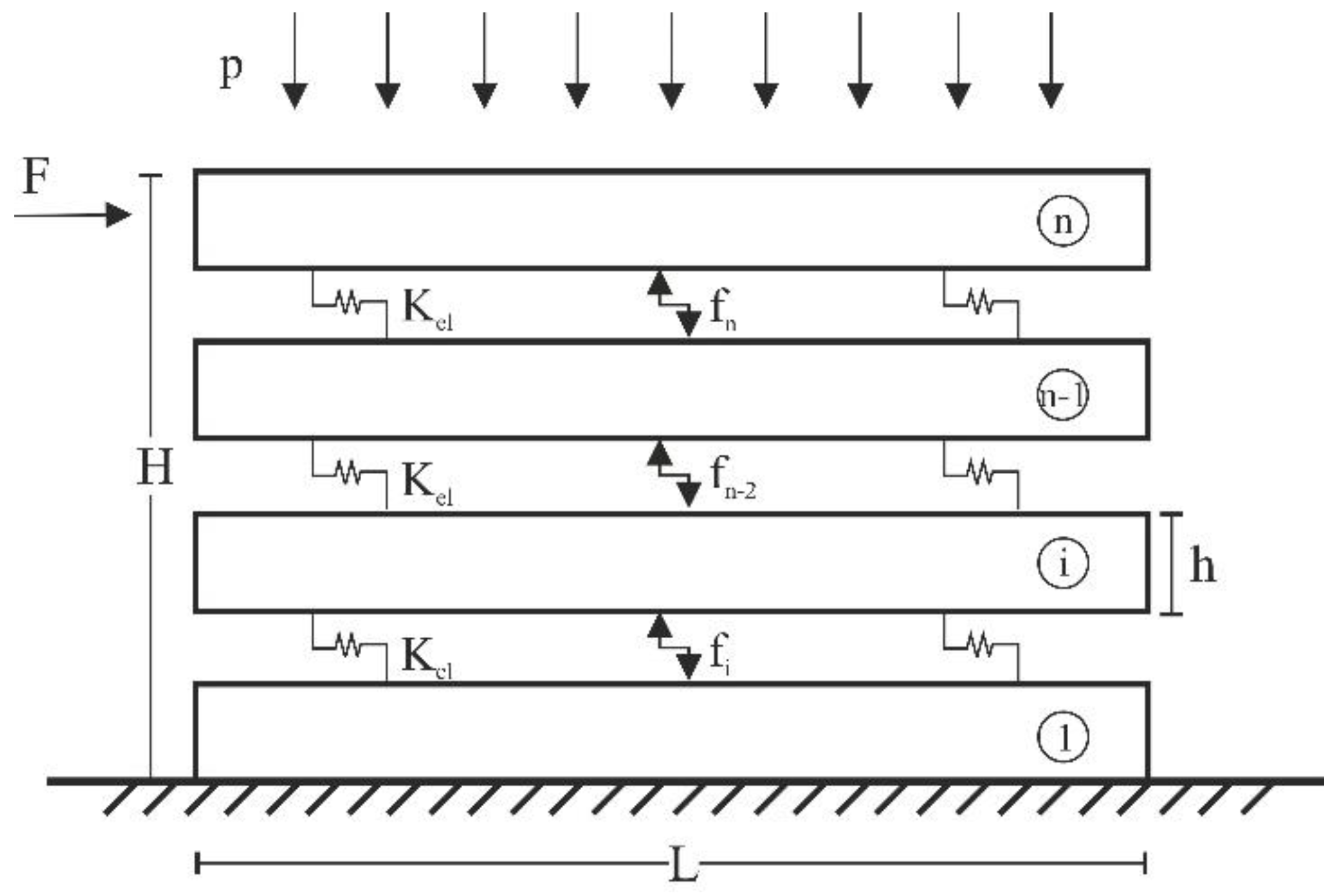
More in detail, the diagonal mass matrix:
M = m [ 1 0 0 0 β m 2 0 0 0 β m 3 ]
depends on the total lumped mass m of the first floor and the j-th floor mass ratios βmj for the upper levels (relative to the first one). The required mass parameters were calculated from the nominal geometries in Figure 4, thus including the inter-story or roof features and the log-walls components. Preliminary calculations resulted in seismic masses of 60 kN, 54.9 kN and 32.0 kN respectively.
At the same time, the diagonal stiffness matrix in Equation (6) is given by:
K = k [ 1 + β k 2 β k 2 0 β k 2 β k 2 + β k 3 β k 3 0 β k 3 β k 3 ]
with k denoting the unknown first-floor stiffness and βkn the relative stiffness values.
According to the elevation views of Figure 4, the required input stiffness values for the examined Blockhaus building were considered proportional to each log-wall length, net to possible door/window openings (if any). Major calculation outcomes are reported in Section 4.2.10.
Once estimated m and k, the natural frequencies ωN (rad/sec) and periods TN (s) for the N-th mode of vibration were thus calculated as:
ω N = α N k m
Additionally
T N = 2 π α N k m = T ¯ α N
respectively, with αN the corresponding natural frequency parameter.

4.2.4. Normalized Modal Analysis

An eigenvalue analysis was then performed for the case-study Blockhaus system, given that the modal participation factor (ΓN) for the N-th mode is conventionally defined as:
Γ N = j = 1 N f l o o r β m j φ j N j = 1 N f l o o r β m j ( φ j N ) 2
with Nfloor= 3 representing the total number of floors, according to the schematic drawings of Figure 4.
In order to measure the contribution of the N-th vibration mode to ΓN, the inter-story drift factor γjN was also introduced, being independent on the normalization process and usually defined as:
γ j N = Γ N ( φ j N φ j 1 , N )

4.2.5. Design of the Inter-Story Drift Spectra

A conversion of the design acceleration response spectrum Sa into a displacement response spectrum was performed, given that:
S d ( T ) = ( T 2 π ) 2 S a ( T )
In Equation (13), Sd is the displacement response of the overall Blockhaus structure object of investigation, once it is modeled as an elastic SDOF system.
Consolidated modal expansion and combination procedures of literature were hence adopted in this research study (with a reference to the Square-Root-of-Sum-of-Squares (SRSS) combination rule [29]), and incorporated into a single equation, so as to generate the inter-story drift spectra:
Δ j ( T ¯ ) = 1 H j n [ γ j n ( T ¯ α n 2 π ) 2 S a ( T ¯ α n ) ] 2
where Hj denotes the inter-story height of each building level (i.e., 2.72 m or 2.56 m respectively, according to Figure 4).

4.2.6. Weakest Floor and Equivalent Stiffness

The weakest floor of the Blockhaus building herein explored was numerically detected by plotting together the inter-story drift spectra for each story level, as also in accordance with Section 4.2.5. In general, see [11,12], the weakest floor for a given structure is in fact generally represented by the first one that reaches the reference limit drift value (see Table 2). Defined the period T ¯ = T ¯ r e q , the other floor drift can be directly estimated. In the case of Blockhaus systems, careful consideration should be spent for shear-walls with openings, since responsible of possible local effects to properly account (see also [19,20,21]).
The equivalent rigidity of each floor, in conclusion, was conventionally estimated as:
( k e q ) j = ( 2 π T ¯ r e q ) 2 m β k j
that is as a function of the required equivalent period, as well as based on the m and βkj parameters for the building previously defined in Equation (7).

4.2.7. Refined Numerical Modeling of Log-Walls and Derivation of the Backbone Parameters

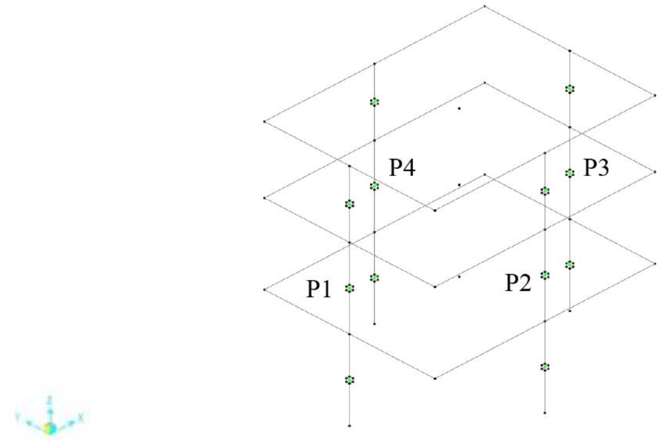
In order to define the backbone parameters of interest for design purposes, a detailed analysis of each main log-wall of Figure 4 was first carried out with the support of refined Finite Element (FE) numerical models. To this aim, each P1-to-P4 was subdivided into three parts in the building elevation, and namely detected as GF (Ground Floor), FF (First Floor) and SF (Second Floor) respectively. Each log-wall portion was thus modeled using the ABAQUS/Explicit software [30], and separately assessed under in-plane lateral loads (i.e., Figure 2).
First, to ensure the consistency and accuracy of FE models reproducing each log-wall portion, preliminary analyses that are not included in this paper, for the sake of clarity, were carried out by modeling a full-size wall having the same geometrical and mechanical features of the test specimens presented in [19]. The numerically obtained load–displacement curve was compared with [19], for a validation of FE assumptions. Accordingly, the same modeling strategy was extended to P1-to-P4 shear log-walls in Figure 4.
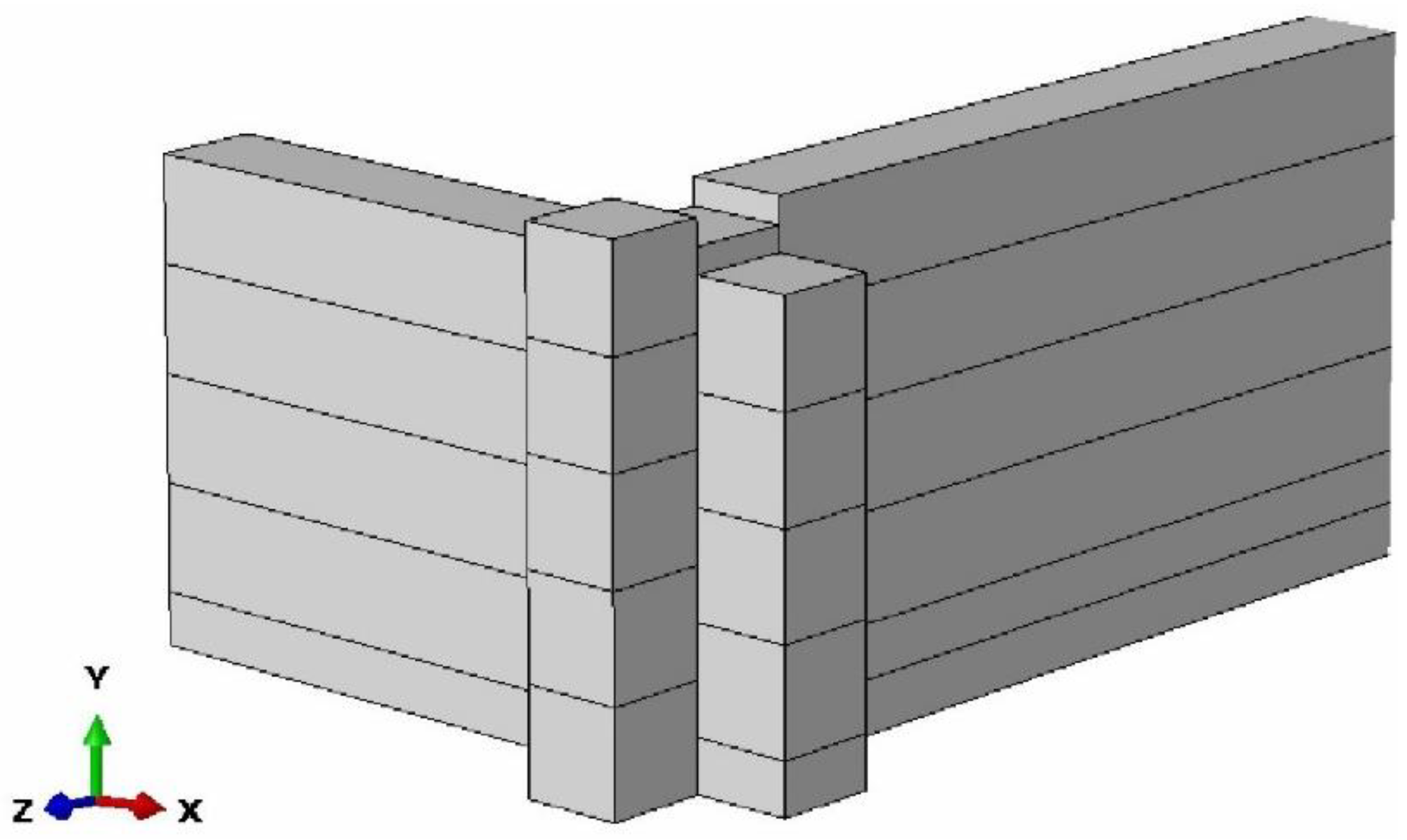
Basically, the whole 3D modeling approach was based on previous research studies, see [20,25] and the detail view in Figure 6. Each FE model was realized via a set of timber components, as obtained from 8-node, linear brick, solid elements with reduced integration (C3D8R) of the ABAQUS element library. Orthogonal log-walls (i.e., outriggers) able to mechanically interact with the shear log-walls were accounted in a fixed total length of 1 m [20]. Simplified rectangular cross-sections (thus deprived of top/bottom notches and protrusions) were used to describe each solid log [20], while the corner joints were accurately reproduced in their nominal geometry. The nominal gap was set in tgap = 1 mm [20,31]. Rigid ideal restraints were taken into account in place of the base angular brackets [20].
C24-resistance class spruce was then numerically described based on the mechanical properties in Table 1, via an orthotropic, equivalent elasto-plastic material. The resistance parameters in the directions of interest were accounted in the form of Hill plastic law, as also reported in [25,32]. More in detail, the compressive resistance perpendicular to the grain (Y-local axis of Figure 6) was set in fc,90 = 3.29 MPa. The other Hill stress ratios were then calculated along the remaining directions (X and Z directions, and XY, XZ and YZ planes for the shear components) were defined so as to reproduce the mean compressive resistance parallel to the grain (f0,c = 30 MPa, X-axis), the mean compressive resistance perpendicular to the grain (f90,c = 3.29 MPa, Z-axis) and the mean shear strength fv = 3.96 MPa (XY, XZ, YZ) for timber. Based on Table 1, the above mean values were calculated in accordance with [33], that is:
f m = f k 1 1.645 C O V [ f k ] ;
with C O V [ f m ] = 10 % for compression perpendicular to the grain and COV [ f m ] = 0.8 g   ( 25 % ) for compression parallel to the grain.
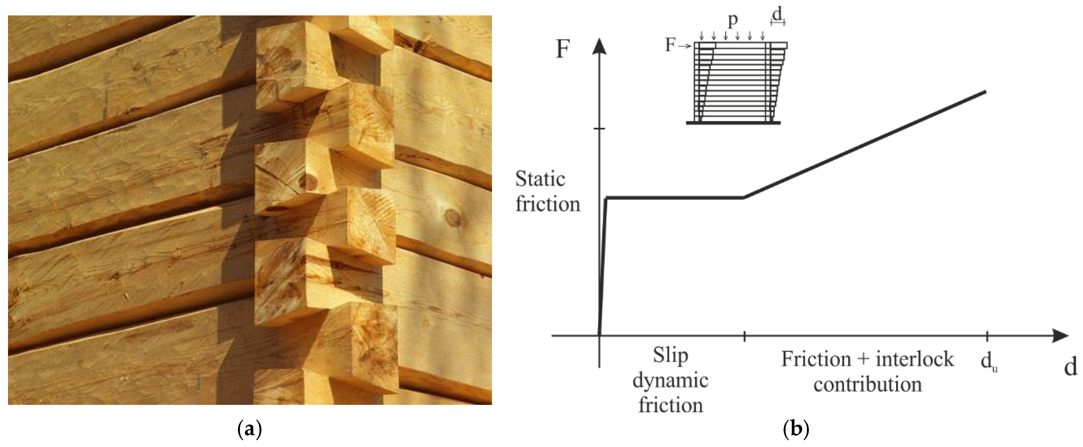
Regarding the contact interactions that were included as a key boundary non-linearity of the reference FE assembly, the “general contact” surface-to-surface formulation was used, as also reported in [20,25]. In the case of overlapping logs, the main input parameter was represented by the static friction coefficient, that was set to μ = 0.5 for the parametric simulations [19,20]. The FE description of door/window openings, finally, was based on the drawings of Figure 4 and on past numerical studies [19,20,31].
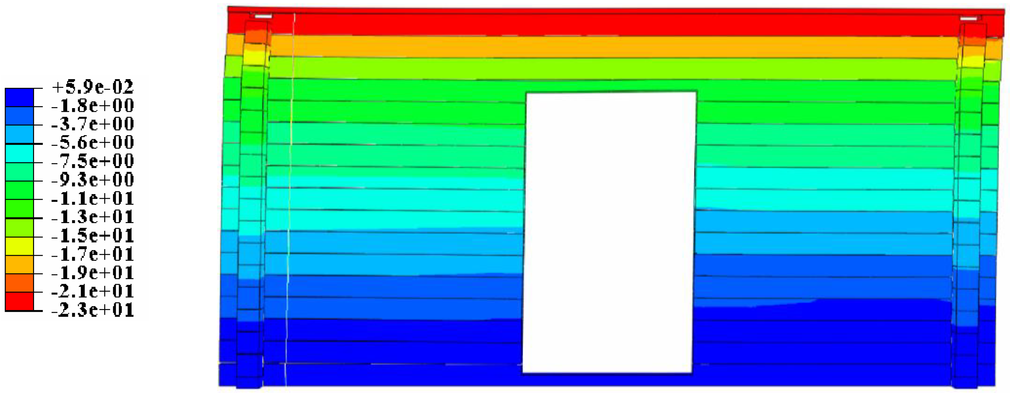
For each log-wall, both an in-plane lateral displacement and a constant vertical pre-compressive load were simultaneously introduced, as also in accordance with [19,20]. Such pressure amplitude was separately calculated, for each wall, so as to reproduce a uniform pre-compressive magnitude. The horizontal in-plane lateral displacement was imposed to the lateral surface of the top beam. The latter (200 mm its maximum value) was selected from [19], being representative of the ultimate allowable lateral displacement for a conventional test setup. The typical deformed shape of a selected log-wall portion (P1-GF) is shown in Figure 7.
Given that the P1-to-P4 log-walls were separately described in ABAQUS and subjected to in-plane lateral displacement/pre-compressive load, the FE results of refined models were separately collected for a further post-processing stage.
An Elasto-Plastic (EP) model was in fact formulated, so that the in-plane load–displacement behavior at the top of each log-wall could be described via a linear SDOF spring with appropriate mechanical parameters. The envelope response of each shear-wall, more in detail, was modeled by means of the following three-parameter non-linear equation:
F b ( d ) = { k 0 d f o r   d d u F u f o r   d > d u
where k0 is the initial tangent stiffness of the backbone curve, Fb represents the restoring force, and Fy = Fu is the maximum load-carrying capacity of the elasto-plastic system, associated with the ultimate displacement du.
The so collected backbone parameters are summarized in Table 3 of each log-wall portion object of study, as obtained from the analytical fitting of FE numerical F-d curves.

4.2.8. Equivalent Linearization of Backbone Curves

The Modal-DBD provides a simplified procedure to define the stiffness of the equivalent linear system. This assumes that the energy stored in each non-linear shear-wall (ENL) must equal the energy of the corresponding linear system (EL). The latter is thus defined for each shear-wall as:
E N L = 0 d t F b ( d )
with Fb(d) previously defined (Equation (17)).
Given that the energy stored in the equivalent elastic system is:
E L = 1 2 k e q d t 2
with dt the target displacement, the equivalent elastic stiffness keq can be hence calculated as:
k e q = 2 E N L d t 2

4.2.9. Shear and Uplift Force Estimation

The story shear force Vj and the base shear can be generally determined as the sum of the actual shear-wall backbone forces (i.e., Fb given by Equation (17)), at the target drift:
V j = w a l l s { F b ( Δ j ( T ¯ r e q ) h ) f o r   Δ j ( T ¯ r e q ) h < d u F u f o r   Δ j ( T ¯ r e q ) h d u
with h the height (net to the floors) of each log-wall.
The maximum uplift force (Fup) is developed on the end studs can be estimated on the basis of the height-to-width ratio h/B of the log-wall segment, that is:
F u p = h w a l l s B V j

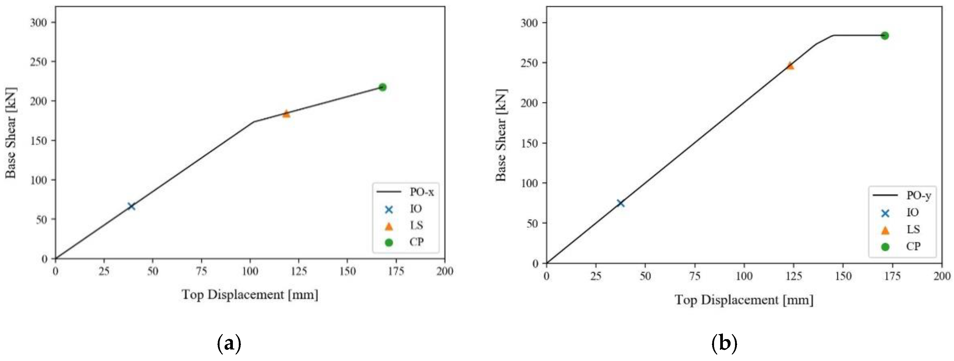
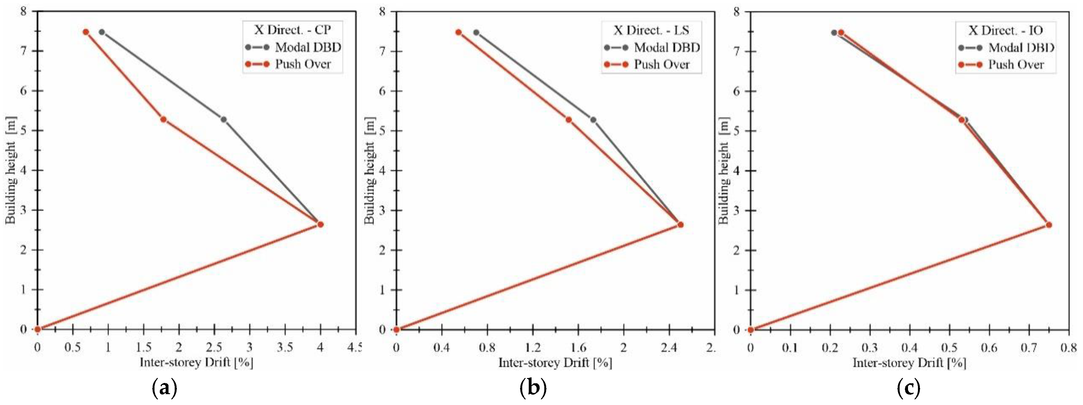
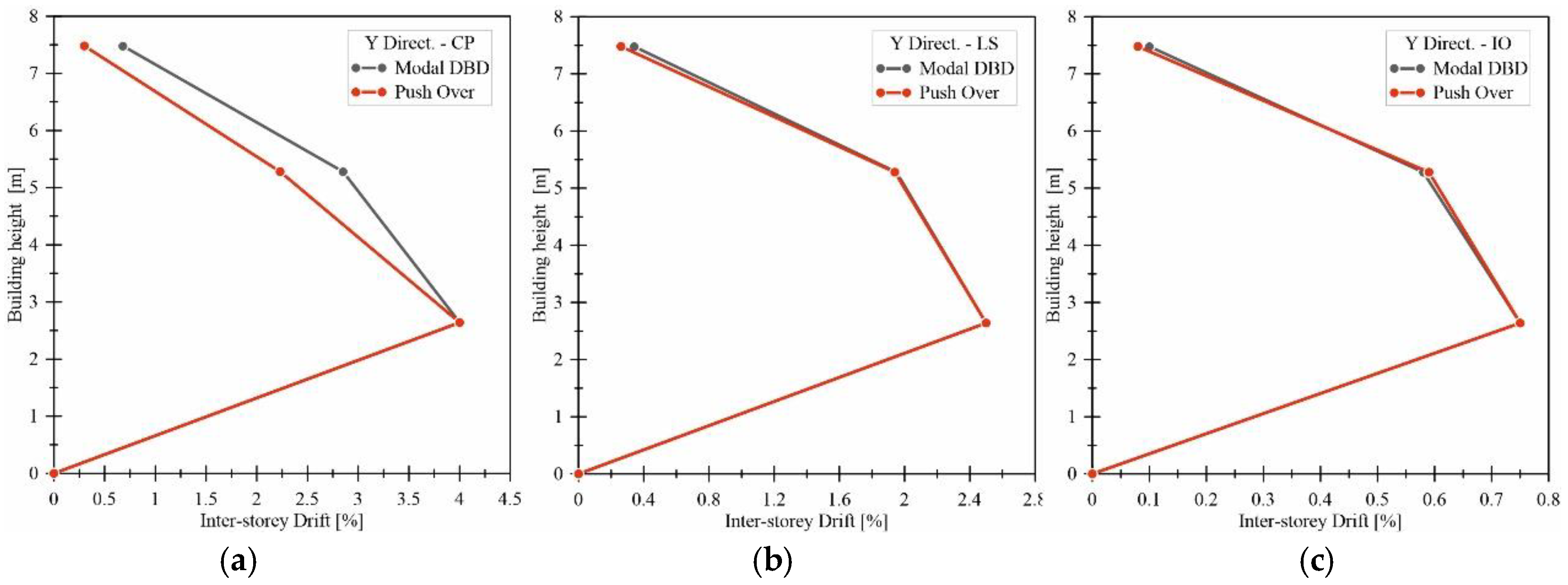
4.2.10. Modal-DBD Application and Results

The mass ratios (βm) were obtained by the analysis of the examined Blockhaus system subjected to self-weight gravity loads and superimposed dead loads. More in detail, the mass ratios for the first, second and third floors (relative to the first one) were estimated in 1.0, 0.90 and 0.53, respectively.
In accordance with [34] the initial βk values (relative to the first floor) were then estimated for each story by calculating the total available shear-wall length in the selected direction. In the X-direction, in particular, these stiffness ratios resulted in 1.0, 0.79 and 0.79 for the first, second and third level, respectively. In the Y-direction, constant stiffness ratios equal to 1.0 were obtained for the first, second and third floor.
The analyses were thus carried out for both X- and Y-directions, starting from the CP level and downwards. The iterative calculation process was carried out as follows:
  • First, an initial estimation of required stiffness values and drift levels was performed;
  • The actual stiffness contributions βk of each log-wall partition (for a given drift level) were then taken into account;
  • Rounded drift have been evaluated from 0.05% up to 4% at intervals of 0.025, the initial estimated drift are rounded to the closet value in the belonging range.
  • As a final step, a new normalized modal analysis was performed (using the actual βk values), in order to obtain new story drift estimates and a corresponding set of required equivalent stiffnesses;
  • For a seismic performance assessment of the case-study building, the actual-to-required stiffness ratio was calculated for each limit state, log-wall and story level.
The overall calculation process was carried out accounting for the stiffness values obtained from the EP model of each log-wall partition (i.e., Table 3). Major calculation outcomes are reported in Table 4, Table 5, Table 6, Table 7, Table 8 and Table 9, grouped by limit state and (X, Y) direction.
As shown, the CP level is largely verified for the case-study Blockhaus system. The stiffness of the building in the X-direction (i.e., east and west log-walls) is in fact up to +27% higher than the minimum required. Regarding the X-direction (i.e., south and north), the estimated stiffness is up to +64% larger than required.
Similar considerations can be derived from the LS level. The stiffness of the actual lateral force resisting system, parallel to the east and west log-walls, is about 40% higher than the minimum required. In the direction parallel to south and north log-walls, such a ratio is up to +65%. The same tables, finally, emphasize that the fixed drift limit of 0.75% for the IO configuration is extremely conservative for Blockhaus systems, given that the intrinsic flexibility of log-walls turns out in stiffness contributions that hardly match the actual required estimates.

5. Validation of the Modal-DBD Analysis

In conclusion, to check the accuracy of the full Modal-DBD process, a Push-Over (PO) analysis was carried out for the examined Blockhaus system of Figure 4, based on a geometrically simplified but still reliable 3D numerical model. In order to further validate a calculation tool in use for design practice, in addition, such a FE model was developed in SAP2000 [35].
As shown in Figure 8, the FE building model was thus fixed at the base, and assembled in a series of Equivalent Energy Elastic-Plastic (EEEP) springs representative of the actual in-plane response of P1-to-P4 log-walls. Careful consideration was spent for the mechanical connection of these springs with the other FE components, as well as for the calibration of their constitutive law (Table 3). The EEEP springs were in fact located at the mid-height of each log-wall, and properly oriented so that they could work in the longitudinal direction only. No additional stiffness was taken into account for the description of the out-of-plane behavior of each log-wall, given that the EEEP constitutive laws of each spring were already able to include the effect of the orthogonal logs. All the springs were linked together by means of rigid elastic frames. A set of in-plane rigid diaphragms with lumped masses, moreover, was taken into account to represent the floors.
The modal load distribution was separately investigated in the primary (X, Y) directions, thus comparing the base-shear load and the top displacement predictions (at the centre of mass of the roof) with the corresponding Modal-DBD estimates. Figure 9 reports the so-obtained PO curves (X- and Y- principal directions), with evidence of the corresponding limit states.
In Table 10 and Table 11, a summary of comparisons is proposed for the X- and Y- directions. In Figure 10 and Figure 11, moreover, the comparison of inter-story displacement obtained by performing a Modal-DBD and a PO analysis, for the X- and Y- directions.
The analysis of Modal-DBD method and PO estimates was performed in terms of shear base forces and top displacements, in both the principal directions, at the CP, LS and IO levels. In particular, see Table 10 and Table 11, the comparative study proved that the Modal-DBD procedure could offer reliable estimates for Blockhaus timber structures (as far as torsional phenomena can be disregarded). The Modal-DBD shear forces were generally found in close correlation with PO predictions. Similarly, the corresponding top displacements were found to be only partly overestimated by the Modal-DBD approach, up to +14% the PO analyses for the selected case-study building.

6. Conclusions

The Modal-Displacement Based Design (DBD) procedure for earthquake-resistant multi-story structures was adapted in this paper and extended to the structural typology of timber Blockhaus systems. The study follows and extends previous research investigations, in which the seismic behavior of full 3D Blockhaus systems was investigated via shake-table tests or refined FE analyses.
As shown, based on the discussion of a case-study three-story building, the Modal-DBD method requires adaptations from its original proposal, as far as the intrinsic features of Blockhaus buildings must be taken into account, and can be efficiently applied to 3D systems with regular shape, relatively symmetric plan and in-plane rigid diaphragms (i.e., negligible torsional effects). As in the case of other timber structures, the inter-story drift was assumed as a key design parameter to predict and control the evolution of damage mechanisms. Accordingly, careful consideration was required for the reliable calibration of the backbone parameters required for the analysis.
For the case-study Blockhaus building presented in the paper, the accuracy and potential of the Modal-DBD approach was assessed with the support of refined, 3D solid Finite Element (FE) numerical models validated to past literature documents, and able to account for the intrinsic features of the Blockhaus structural typology. The so collected FE predictions were thus further post-processed, for the definition of a simplified and computationally efficient elasto-plastic (EP) model of practical use for design. Both the Collapse Prevention (CP) and Life Safeguard (LS) performance levels were found to be largely verified, with relatively high stiffness estimates, with respect to the minimum required values (up to +65%). The same FE simulations, however, also emphasized that a reference drift limit of 0.75% for the Immediate Occupancy (IO) level would result in a severely conservative assumption for Blockhaus systems, that the shear log-walls (due to the presence of small mounting gaps in the corner joints and high deformation capacity) would hardly satisfy. The EP model, in conclusion, was further validated by means of a Push-Over (PO) analysis of the selected 3D building. From the comparison of key parameters for the seismic response assessment, it was shown that the expected base shear forces could be properly estimated by the Modal-DBD procedure. Similarly, the corresponding top displacements were found to be only slightly overestimated, up to a maximum of +14% of the corresponding PO predictions (for the CP performance level).

Author Contributions

This paper results from a joint collaboration of all the involved authors (M.S., V.R., C.B. and M.F.). All authors have read and agreed to the published version of the manuscript.

Funding

This research received no external funding.

Conflicts of Interest

The authors declare no conflict of interest.

References

  1. Foliente, G.C. Developments in performance-based building codes and standards. For. Prod. J. 2000, 50, 12–21. [Google Scholar]
  2. Poland, C.; Hill, J.; Sharpe, R.; Soulages, J. Vision 2000 Committee & California. In Performance Based Seismic Engineering of Buildings; Structural Engineers Association of California: Sacramento, CA, USA; California Office of Emergency Services: Sacramento, CA, USA, 1995. [Google Scholar]
  3. International Code Council. International Building Code; ICC: Washington, DC, USA, 2018. [Google Scholar]
  4. The American Society of Civil Engineers. Seismic Evaluation and Retrofit of Existing Buildings; ASCE/SEI 41–17: Reston, VA, USA, 2017. [Google Scholar]
  5. The American Society of Civil Engineers. Minimum Design Loads for Buildings and Other Structures (ASCE/SEI 7-16); ASCE/SEI: Reston, VA, USA, 2016. [Google Scholar] [CrossRef]
  6. Calvi, G.; Priestley, M.; Kowalsky, M. Displacement Based Seismic Design of Structures; Iuss Press: Pavia, Italy, 2007. [Google Scholar]
  7. Gkimprixis, A.; Tubaldi, E.; Douglas, J. Comparison of methods to develop risk-targeted seismic design maps. Bull. Earthq. Eng. 2019, 17, 3727–3752. [Google Scholar] [CrossRef] [Green Version]
  8. Priestley, M.J.N. Direct displacement-based design of precast/prestressed concrete buildings. PCI J. 2002, 47, 66–79. [Google Scholar] [CrossRef]
  9. Ahmadi, F.; Mavros, M.; Klingner, R.E.; Shing, B.; McLean, D. Displacement-based seismic design for reinforced masonry shear-wall structures, part 1: Background and trial application. Earthq. Spectra. 2015, 31, 969–998. [Google Scholar] [CrossRef]
  10. Fajfar, P.; Gašperšič, P. The N2 method for the seismic damage analysis of RC buildings. Earthq. Eng. Struct. Dyn. 1996, D25, 31–46. [Google Scholar] [CrossRef]
  11. Pang, W.; Rosowsky, D.V. Direct displacement procedure for performance-based seismic design of mid-rise wood-framed structures. Earthq. Spectra 2009, 25, 583–605. [Google Scholar] [CrossRef]
  12. Pang, W.; Rosowsky, D. Direct Displacement Procedure for Performance-Based Seismic Design of Multistory Woodframe Structures; Technical Report MCEER-10-0001; ISSN 1520-295X. 2010. Available online: https://ubir.buffalo.edu/xmlui/bitstream/handle/10477/25348/10-0001.pdf?sequence=3 (accessed on 25 April 2020).
  13. European Committee for Standardization (CEN). Eurocode 8: Design of Structures for Earthquake Resistance—Part 1: General Rules, Seismic Actions and Rules for Buildings (EN 1998-1: 2004); European Committee for Normalization: Brussels, Belgium, 2014. [Google Scholar]
  14. Loss, C.; Tannert, T.; Tesfamariam, S. State-of-the-art review of displacement-based seismic design of timber buildings. Constr. Build. Mater. 2018, 191, 481–497. [Google Scholar] [CrossRef]
  15. Bahmani, P.; Van De Lindt, J.W.; Dao, T.N. Displacement-based design of buildings with torsion: Theory and verification. J. Struct. Eng. 2014. [Google Scholar] [CrossRef]
  16. Fischer, D.; Filiatrault, A.; Folz, B.; Uang, C.; Seible, F. Shake Table Tests of a Two-Story Woodframe House; CUREE Report; Consortium of Universities for Research in Earthquake Engineering: Richmond, CA, USA, 2001. [Google Scholar]
  17. Federal Emergency Management Agency. Prestandard and Commentary for the Seismic Rehabilitation of Buildings; FEMA 356: Washington, DC, USA, 2000. [Google Scholar]
  18. Bolvardi, V.; Pei, S.; van de Lindt, J.W.; Dolan, J.D. Direct displacement design of tall cross laminated timber platform buildings with inter-story isolation. Eng. Struct. 2018, 167, 740–749. [Google Scholar] [CrossRef]
  19. Bedon, C.; Rinaldin, G.; Fragiacomo, M. Non-linear modelling of the in-plane seismic behaviour of timber Blockhaus log-walls. Eng. Struct. 2015, 91, 112–124. [Google Scholar] [CrossRef] [Green Version]
  20. Bedon, C.; Fragiacomo, M.; Amadio, C.; Sadoch, C. Experimental study and numerical investigation of Blockhaus shear walls subjected to in-plane seismic loads. J. Struct. Eng. 2014, 141. [Google Scholar] [CrossRef]
  21. Grossi, P.; Sartori, T.; Giongo, I.; Tomasi, R. Analysis of timber log-house construction system via experimental testing and analytical modelling. Constr. Build. Mater. 2016, 102, 1127–1144. [Google Scholar] [CrossRef]
  22. Branco, J.; Araújo, J.P. Lateral Resistance of Log Timber Walls Subjected to Horizontal Loads. In Proceedings of the 11th World Conference on Timber Engineering WCTE, Riva del Garda—Trentino Alto Adige, Italy, 20–24 June 2010. [Google Scholar]
  23. Seismic Engineering Research Infrastructures for European Synergies. In Seismic Performance of Multi-Storey Timber Buildings–Rusticasa Building–Final Report; TIMBER BUILDINGS Project, SERIES WP9-TA5 LNEC; 2013.
  24. Bedon, C.; Rinaldin, G.; Fragiacomo, M.; Noé. q-factor estimation for 3D log-house timber buildings via Finite Element analyses. Soil Dyn. Earthq. Eng. 2019, 116, 215–229. [Google Scholar] [CrossRef]
  25. Sciomenta, M.; Bedon, C.; Fragiacomo, M.; Luongo, A. Shear performance assessment of timber log-house walls under in-plane lateral loads via numerical and analytical modelling. Buildings 2018, 8, 99. [Google Scholar] [CrossRef] [Green Version]
  26. Pei, S.; Van De Lindt, J.W.; Wehbe, N.; Liu, H. Experimental study of collapse limits for wood frame shear walls. J. Struct. Eng. 2013, 1489–1497. [Google Scholar] [CrossRef]
  27. Van De Lindt, J.W.; Pei, S.; Pryor, S.E.; Shimizu, H.; Isoda, H. Experimental seismic response of a full-scale six-story light-frame wood building. J. Struct. Eng 2010, 136, 1262–1272. [Google Scholar] [CrossRef]
  28. USGS—Unified Hazard Tool. Available online: https://earthquake.usgs.gov/hazards/interactive/ (accessed on 25 April 2020).
  29. Chopra, A. Dynamics of Structures: Theory and Applications to Earthquake Engineering, 2nd ed.; Prentice-Hall Inc.: Upper Saddle River, NJ, USA, 2001. [Google Scholar] [CrossRef]
  30. Dassault Systèmes Simulia. Abaqus, F.E.A. v. 6.12 Computer Software; Dassault Systèmes Simulia: Providence, RI, USA, 2015. [Google Scholar]
  31. Bedon, C.; Rinaldin, G.; Izzi, M.; Fragiacomo, M.; Amadio, C. Assessment of the structural stability of Blockhaus timber log-walls under in-plane compression via full-scale buckling experiments. Constr. Buid. Mater. 2015, 78, 474–490. [Google Scholar] [CrossRef] [Green Version]
  32. Bedon, C.; Fragiacomo, M. Numerical analysis of timber-to-timber joints and composite beams with inclined self-tapping screws. Compos. Struct. 2019, 207, 13–28. [Google Scholar] [CrossRef]
  33. JCSS. Probabilistic Model Code—Part 3: Resistance Models. Available online: https://www.jcss-lc.org/publications/jcsspmc/part_iii.pdf (accessed on 25 April 2020).
  34. Filiatrault, A.; Folz, B. Performance-based seismic design of wood framed buildings. J. Struct. Eng. 2002, 39–47. [Google Scholar] [CrossRef]
  35. Computers and Structures Inc. SAP2000 Integrated Software for Structural Analysis and Design; CSI: Berkeley, CA, USA, 2019. [Google Scholar]
Figure 1. General flowchart for the application of the Modal-Displacement-Based Design (DBD) procedure to multi-story buildings.
Applsci 10 03889 g001
Figure 2. Typical examples of (a) corner joint features and (b) in-plane lateral response for timber Blockhaus shear-walls under monotonic loads (figure reproduced from [21] with permission from Elsevier®, Copyright License Agreement n. 4681430084070, October 2019).
Applsci 10 03889 g002
Figure 3. Mechanical model of a typical log-house shear-wall under combined in-plane compression and lateral loads (front view). Reproduced from [25] under the terms and condition of CC BY-NC 4.0 license.
Applsci 10 03889 g003
Figure 4. Case-study system: (a,b) floor views and (cf) elevation views (dimensions in m).
Applsci 10 03889 g004
Figure 5. Design acceleration response spectra for Eureka (CA, USA), in accordance with [5].
Applsci 10 03889 g005
Figure 6. Corner joint detail of the typical Blockhaus FE model (ABAQUS, with hidden mesh).
Applsci 10 03889 g006
Figure 7. Contour plot of in-plane lateral displacement of the P1-GF portion of log-wall (ABAQUS, legend values in mm).
Applsci 10 03889 g007
Figure 8. Axonometric view of the simplified 3D model for the Push-Over (PO) analysis of the case-study Blockhaus system (SAP2000 [35]).
Applsci 10 03889 g008
Figure 9. Push Over curves: results for (a) X- and (b) Y- directions.
Applsci 10 03889 g009
Figure 10. Comparison of inter-story displacements obtained from the Modal-DBD or the PO analyses in the X-direction (a) Collapse Prevention, (b) Life Safety and (c) Immediate Occupancy.
Applsci 10 03889 g010
Figure 11. Comparison of inter-story displacements obtained from the Modal-DBD or the PO analyses in the Y-direction (a) Collapse Prevention, (b) Life Safety and (c) Immediate Occupancy.
Applsci 10 03889 g011
Table 1. Nominal mechanical properties of Scots Pine wood (Pinus sylvestris L.), resistance class C24 according to [22].
PropertySymbol/UnitNominal Value
Bending strengthfm,k (N/mm2)24
Tensile strengthft,90,k (N/mm2)14
ft,0,k (N/mm2)0.5
Compressive strengthfc,90,k (N/mm2)21
fc,0,k (N/mm2)2.5
Modulus of ElasticityE0,mean (N/mm2)11,000
E90,mean (N/mm2)370
Shear ModulusGmean (N/mm2)690
Densityρ (kg/m2)530
Poisson’s ratioν0.3
Table 2. Allowable inter-story drift for structures “other than masonry”, according to ASCE/SEI-7 provisions [5], or herein proposed for Blockhaus systems.
Performance ExpectationsDrift Limit
(%)
LevelExceedance Probability
(%/50 years)
Values from [5] for “Other than Masonry”Proposal for Blockhaus Systems
IO500.50.75
LS1012.5
CP224
Table 3. Shear-wall backbone parameters.
Log WallFy = Fu (kN)d (mm)du (mm)k0 (kN/mm)μ
P1_GF130.52521982.513.8
P2_GF144.57791991.832.51
P3_GF104.961282000.821.56
P4_GF138.7731991.92.72
P1_FF133.40581972.303.42
P2_FF134.52761971.772.59
P3_FF110.241061991.041.87
P4_FF138.51811961.712.43
P1_SF131.44532002.483.75
P2_SF146.25251955.857.71
P3_SF127.19792001.612.54
P4_SF148.98261955.737.48
Table 4. Collapse prevention (CP) level analysis (X-direction), accounting for the Elasto-Plastic (EP) shear-wall stiffnesses.
Initial EstimationShear-Wall AssessmentDesign Verification
CP LevelStoryInitial βkDrift (%)Required keq (kN/mm)Rounded Drift (%)Actual keq (kN/mm)Actual βkDrift (%)Required keq (kN/mm)keq Actual/Required
P1Log Wall IDP3Log Wall IDTotal
114.001.714.001.86GF0.82GF2.6814.002.121.26
20.793.791.353.751.90FF1.04FF2.941.092.632.311.27
30.792.081.352.002.48SF1.61SF4.091.520.923.231.27
Table 5. Life Safety (LS) level analysis (X-direction), accounting for the EP shear-wall stiffnesses.
Initial EstimationShear-Wall AssessmentDesign Verification
LS LevelStoryInitial βkDrift (%)Required keq (kN/mm)Rounded Drift (%)Actual keq (kN/mm)Actual βkDrift (%)Required keq (kN/mm)keq Actual/Required
P1Log Wall IDP3Log Wall IDTotal
112.502.372.502.36GF0.82GF3.2112.502.291.40
21.091.642.581.752.3FF1.04FF3.341.041.732.381.40
31.520.573.610.502.48SF1.61SF4.091.270.702.911.40
Table 6. Immediate Occupancy (IO) level analysis (X-direction), accounting for the EP shear-wall stiffnesses.
Initial EstimationShear-Wall AssessmentDesign Verification
IO LevelStoryInitial βkDrift (%)Required keq (kN/mm)Rounded Drift (%)Actual keq (kN/mm)Actual βkDrift (%)Required keq (kN/mm)keq Actual/Required
P1Log Wall IDP3Log Wall IDTotal
110.754.570.752.51GF0.82GF3.3310.754.550.73
21.040.514.750.502.3FF1.04FF3.341.000.544.550.73
31.270.215.800.502.48SF1.61SF4.091.230.215.600.73
Table 7. CP level analysis (Y-direction), accounting for the EP shear-wall stiffnesses.
Initial EstimationShear-Wall AssessmentDesign Verification
CP LevelStoryInitial βkDrift (%)Required keq (kN/mm)Rounded Drift (%)Actual keq (kN/mm)Actual βkDrift (%)Required keq (kN/mm)keq Actual/Required
P2Log Wall IDP4Log Wall IDTotal
114.001.984.001.71GF1.72GF3.4314.002.091.64
212.911.983.001.76FF1.71FF3.471.012.852.111.64
311.881.982.004.26SF4.25SF8.512.480.685.191.64
Table 8. LS level analysis (Y-direction), accounting for the EP shear-wall stiffnesses.
Initial EstimationShear-Wall AssessmentDesign Verification
LS LevelStoryInitial βkDrift (%)Required keq (kN/mm)Rounded Drift (%)Actual keq (kN/mm)Actual βkDrift (%)Required keq (kN/mm)keq Actual/Required
P2Log Wall IDP4Log Wall IDTotal
112.502.342.501.83GF1.9GF3.7312.502.261.65
21.011.782.361.751.77FF1.71FF3.480.931.952.101.66
32.480.425.800.55.85SF5.73SF11.583.100.347.001.65
Table 9. IO level analysis (Y-direction), accounting for the EP shear-wall stiffnesses.
Initial EstimationShear-Wall AssessmentDesign Verification
IO LevelStoryInitial βkDrift (%)Required keq (kN/mm)Rounded Drift (%)Actual keq (kN/mm)Actual βkDrift (%)Required keq (kN/mm)keq Actual/Required
P2Log Wall IDP4Log Wall IDTotal
110.754.560.751.83GF1.90GF3.7310.754.560.82
20.930.584.250.501.77FF1.71FF3.480.930.584.250.82
33.100.1014.160.55.85SF5.73SF11.583.100.114.160.82
Table 10. Comparison between base shear forces and top displacements obtained by Modal-DBD procedure and simplified PO analysis (X-direction). Δ = 100 × (vDBDvPO)/vPO.
X-Direction
Modal-DBDPush-OverΔ (%)
Base Shear (kN)Top Disp.(mm)Base Shear (kN)Top Disp. (mm)Base ShearTop Disp.
CP216.0195.2217.4168.0+0.65+13.98
LS184.0127.0184.5118.5+0.24+6.77
IO65.038.666.439.0+2.17−0.84
Table 11. Comparison between base shear forces and top displacements obtained by Modal-DBD procedure and simplified PO (Y-direction). Δ = 100 × (vDBDvPO)/vPO.
Y-Direction
Modal-DBDPush-OverΔ (%)
Base Shear (kN)Top Disp. (mm)Base Shear (kN)Top Disp. (mm)Base ShearTop Disp.
CP283.0195.8283.7170.9+0.24+12.72
LS246.0124.9246.5123.0+0.21+1.57
IO73.037.375.237.5+2.95−0.50

