Article

Research on Variable Transmission Ratio Control Method to Improve Vehicle Handling Comfort Based on Steer-by-Wire System

1
College of Mechanical Engineering and Automation, Huaqiao University, Xiamen 361021, China
2
Xiamen King Long United Automotive Industry Co., Ltd., Xiamen 361023, China
*
Author to whom correspondence should be addressed.
Actuators 2024, 13(2), 48; https://doi.org/10.3390/act13020048
Submission received: 22 December 2023 / Revised: 19 January 2024 / Accepted: 22 January 2024 / Published: 26 January 2024
(This article belongs to the Special Issue Actuators and Control of Intelligent Electric Vehicles)

Abstract

:
The steer-by-wire system severs the mechanical link between the steering wheel and the steering gear. This configuration enhances the angular transmission characteristics. Entering the nonlinear region of the tires could result in a reduction in the vehicle’s steering gain. In order to improve the comfort of vehicle steering operation, we have developed a variable transmission ratio controller for the steer-by-wire (SBW) system. This controller utilizes information on the vehicle speed and steering wheel angle to generate a variable transmission ratio coefficient, thereby adjusting the steering ratio. We introduce a multi-objective comprehensive evaluation index that takes into account vehicle lateral deviation, driver steering burden, vehicle stability, and safety. To harmonize the transmission ratio weights of constant steering gain, we employ the coefficient of variation method. Ultimately, a fuzzy neural network is employed to craft a nonlinear controller. We conducted steady-state circular motion tests, double lane-change tests, and step input tests to validate the performance of the variable transmission ratio control. The results suggest that, in comparison to conventional fixed transmission ratio systems, the variable transmission ratio control within the steer-by-wire system significantly alleviates the driver’s operational burden while enhancing the vehicle’s handling stability and safety.

1. Introduction

With the continuous progression of automotive technology, the steering system plays a crucial role in influencing the handling and safety of vehicles [1,2]. Its main purpose is to enhance the steering response characteristics of the vehicle by regulating the angles of the front wheels. As a result, the control of variable transmission ratios has become a notable research emphasis in the field of automotive engineering [3,4,5].
The adoption of steer-by-wire technology, characterized by the substitution of traditional mechanical linkages with actuators, has garnered increased interest among researchers in recent times [6,7,8,9]. Owing to the mechanical limitations inherent in traditional steering systems, these constraints impede the potential of variable transmission ratio control strategies. Consequently, the application of steer-by-wire technology in vehicle steering control has propelled the rapid advancement of variable transmission ratio technology. This is attributed to the steer-by-wire system eliminating the mechanical connection between the steering wheel and the steering gear, achieving structural decoupling, and broadening the vehicle’s torque transmission and angle transmission characteristics [10]. Figure 1 depicts the fundamental structure of a commercial vehicle’s steer-by-wire system. In contrast to traditional steering systems, the SBW system can significantly enhance the vehicle’s maneuvering performance while improving driver safety and comfort.
To enhance the overall vehicle’s state response, variable transmission ratio control technology is developed based on the steering system’s structure or characteristics. Fahami proposed integrating front wheel angle as feedback into the control strategy of the variable transmission ratio controller, aiming to improve the vehicle’s maneuverability [11]. Krishna utilized fuzzy control techniques to enhance the yaw stability of steer-by-wire vehicles [12]. Azzalini and others adopted a fuzzy adaptive approach, presenting a variable steering ratio method with a time gradient to assess the “danger” level of driving conditions [13]. Bianchi and others proposed a novel active front-wheel control scheme using the approximating properties of neural networks. This approach improves vehicle stability and handling by employing approximators to estimate tire characteristics and real-time learning of unknown non-linearities. The study confirms the promising prospects of this method for future research [14]. Yang et al. implemented a variable transmission ratio strategy based on the adaptive neuro-fuzzy inference system and an active front steering controller using integral sliding mode to track the desired yaw rate, ultimately enhancing the vehicle’s maneuvering stability [15]. Zhang’s findings from simulation comparisons indicate that a variable transmission ratio control strategy based on generalized Boolean algebra exhibits greater stability than fuzzy control [16]. Zhai designed a novel steer-by-wire control system considering the reactive torque diagram and variable transmission ratio, and the system’s stability was verified through simulation [17].
On the other hand, seeking and maintaining the optimal steering gain for the driver or the vehicle, Zhang determined the optimal variable angle transmission ratio through feedforward control based on a constant yaw rate gain [18]. Li conducted an analysis of the influence of steering sensitivity and yaw rate gain, employing a genetic algorithm to optimize the yaw rate gain. Furthermore, steering ratios were devised for varying vehicle speeds and steering wheel angles to bolster the maneuvering stability and safety of the vehicle [19]. Liu and colleagues conducted distinct investigations into transmission ratios for intelligent vehicles operating in both manual and autonomous driving modes. They employed particle swarm optimization algorithms and fuzzy control to formulate the vehicle’s transmission ratios [20]. Zou and collaborators introduced a vehicle transmission ratio control strategy grounded in driving styles. This approach utilizes the K-means clustering algorithm to categorize driving styles and subsequently tailors personalized variable transmission ratios based on ideal transmission characteristics [21].
Additionally, buses exhibit characteristics such as large mass, high center of gravity, and substantial volume. During curves, the centrifugal force induces vehicle body roll. Operational errors by the driver or insufficient tire adhesion pose a risk of vehicle overturning, particularly during emergency steering maneuvers [22]. Thus, ensuring vehicle safety requires the capability to stabilize the vehicle’s lateral inclination, necessitating the maintenance of the vehicle’s state within a reasonable range through appropriate control strategies. Hu proposed an enhanced sliding mode controller to maintain the vehicle’s roll angle within a safe range [23]. Yang, considering the lateral inclination index as a key parameter for roll control, introduced an improved dynamic rollover index to accurately identify vehicle rollover events and enhance control effectiveness [24]. Given the highly coupled nature of vehicle dynamics, Tian suggested a force-driven switching model predictive control (MPC) strategy that considers both lateral dynamics and roll dynamics models [25]. For enhanced controller performance, Rahul proposed an evolutionary algorithm to solve the quadratic cost function for MPC, addressing the challenge of finding the optimal solution for the MPC cost function [26]. To bolster vehicle safety, Ding proposed an evaluation system incorporating lateral stability based on tire force estimation [27].
While there has been notable progress in prior research on steering systems, a knowledge gap persists concerning the transmission ratio variation mechanism and the practical applications of steer-by-wire systems. Based on the aforementioned discussions, this study aims to utilize the angular transmission characteristics of SBW to enhance the vehicle’s steering response. The variable transmission ratio control of SBW takes into account both objective evaluation indicators for vehicle handling performance and body posture response. In the formulation of variable transmission ratios, factors such as yaw rate gain, lateral acceleration gain, and roll angle gain are comprehensively examined to achieve a stable steering gain. By designing variable transmission ratio coefficients, the handling performance of SBW vehicles is enhanced, ensuring a consistent steering gain for the driver.
The rest of this paper is organized as follows. In Section 2, the vehicle simulation model for path tracking is established. In Section 3, a variable gear ratio controller based on steering gain and comprehensive evaluation metrics is developed. In Section 4, the simulation experimental results of the proposed control method under different operating conditions are analyzed. Conclusions and further work are given in Section 5.

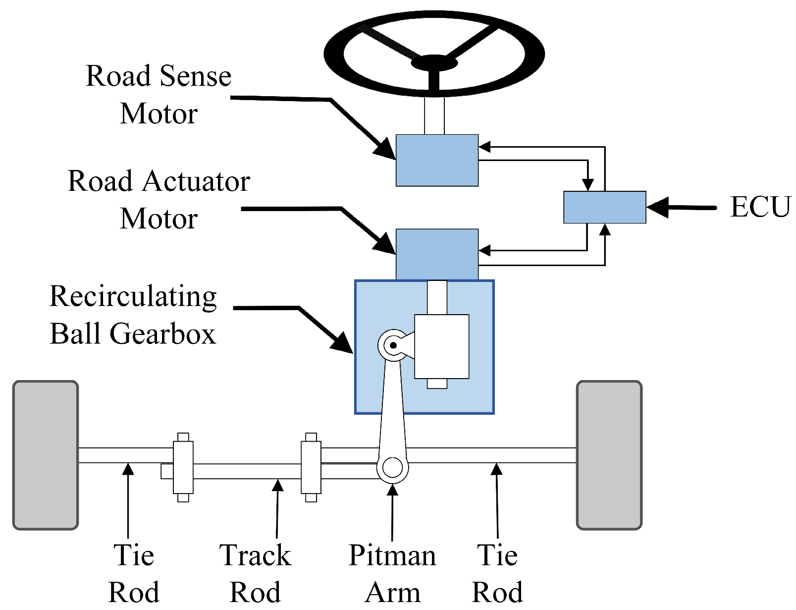
2. Vehicle Simulation System

To investigate the steering characteristics of a vehicle with a variable speed ratio, it is imperative to meticulously design the driver executor, ensuring the completeness of the steering control process. The vehicle is an intricate system characterized by robust coupling and nonlinear features, prompting the exploration of various modeling approaches. The linear two-degrees-of-freedom (2-DOF) model encompasses lateral and yaw motion, thereby simplifying system complexity and aptly capturing vehicle handling performance. Consequently, the 2-DOF model stands as a prevalent approach for scrutinizing vehicle steering [28,29]. As demonstrated in Figure 2, this model adeptly portrays the lateral and yaw motion of a bus. The equations governing the 2-DOF model are as follows:
m v y ˙ + v x γ r = F f + F r
I z γ r ˙ = a F f + b F r
Y ˙ = v y + v x ψ
In the above expressions, m denotes the vehicle mass, v x corresponds to the vehicle speed, v y represents the lateral velocity of the vehicle, γ r denotes the yaw rate, Y signifies the lateral displacement of the vehicle, ψ stands for the yaw angle of the vehicle, I z is the moment of inertia of the vehicle about the z -axis, a and b are the distances from the center of gravity to the front and rear axles. Furthermore, F f and F r denote the lateral forces on the front and rear wheels. Assuming a small tire slip angle, F f = C f α f and F r = C r α r , where C f and C r denote the lateral stiffness of the front and rear wheels, and α f and α r represent the slip angles of the front and rear wheels, respectively.
α f = δ f v y + a γ r v x
α r = v y b γ r v x
where δ f represents the front wheel steering angle desired by the driver; the vehicle parameters are detailed in Table 1. Utilizing the aforementioned dynamic equations, the system can be expressed in state-space form.
x ˙ = 0 v x 1 0 0 0 0 1 0 0 A 33 A 34 0 0 A 43 A 44 x + 0 0 B 3 B 4 u
y = C x
where x = Y ψ v y γ r , y = Y , u = δ f , A 33 = C f + C r m v x , A 34 = a C f b C r m v x v x , A 43 = a C f b C r I z v x , A 44 = a 2 C f + b 2 C r I z v x , B 3 = C f m , B 3 = a C f I z , C = 1 0 0 0 .

3. Variable Steering Ratio Design

The schematic representation of the steer-by-wire system is presented in Figure 1. The steering wheel subsystem conveys the steering wheel angle to the electronic control unit (ECU), which subsequently transmits the target angle to the steering actuator. A mechanical linkage establishes the connection between the steering actuator and the front wheels of the vehicle. Thus, the angular transmission ratio of the SBW system is defined as follows:
i = θ s w δ f = θ s w δ p · δ p δ f = β · i f p
In the equation, i represents the transmission ratio from the steering wheel to the front wheels of the vehicle, θ s w denotes the steering wheel angle, δ f signifies the front wheel angle, δ p represents the steering actuator angle, β stands for the variable transmission ratio coefficient, the designated design target, and i f p denotes the fixed transmission ratio of the mechanical structure.

3.1. Based on the Evaluation Indicators for Vehicle Handling Stability

A holistic indicator for vehicle handling stability as the objective function in the design of variable transmission ratio coefficients is proposed. This incorporates assessment criteria for lateral deviation, encompassing vehicle path tracking, the driver’s steering effort, and criteria for vehicle stability and safety.
J 1 = 0 t e e t 2 d t
J 2 = 0 t θ ˙ s w θ ˙ s w t 2 d t
J 3 = 0 t a y a y t 2 d t
J 4 = 0 t φ φ t 2 d t
J = J 1 2 + J 2 2 + J 3 2 + J 4 2 4
where J 1 denotes the path tracking indicator, J 2 signifies the driver’s steering effort indicator, J 3 represents the vehicle stability indicator, and J 4 denotes the vehicle safety indicator. e t , θ ˙ s w t , a y t , and φ t are the evaluation thresholds for objective evaluation indicators, and t represents the experiment time. Ultimately, these evaluation functions are normalized to derive the performance indicator J , where a smaller value of the indicator indicates better vehicle handling stability.
To examine the outcomes of diverse comprehensive performance indicators across varying variable transmission ratio coefficients β J , dual-lane change test conditions were chosen for simulation. The human–vehicle simulation system was utilized to characterize the vehicle’s steering performance, with the vehicle speed ranging from 20 to 100 km/h. Figure 3 and Figure 4 illustrate the findings of the simulation experiments.
Figure 3 illustrates the simulation results of the comprehensive evaluation indicators. Across varying vehicle speeds, an optimal value of the variable transmission ratio coefficient is evident, corresponding to the comprehensive evaluation indicator. The figure depicts that, with increasing vehicle speed, the variable transmission ratio coefficient grows larger, aligning with the design expectation of light steering at low speeds and stable steering at high speeds. Moreover, it is necessary to constrain the variable transmission ratio coefficient within a specific range to adhere to the position constraints of the mechanical structure and steering response limits. Given that the bus speed typically does not exceed 80 km/h, the lower limit of the variable transmission ratio coefficient is set as β J _ m i n = 0.4 , and the upper limit is established as β J _ m a x = 1.4 . Employing the comprehensive evaluation indicators method, the variable transmission ratio coefficient is correlated with the vehicle speed, resulting in Equation (14):
β J = β J _ m i n ,     v x v 0 β J , v 0 < v x < v 1 β J _ m a x , v 1 v x

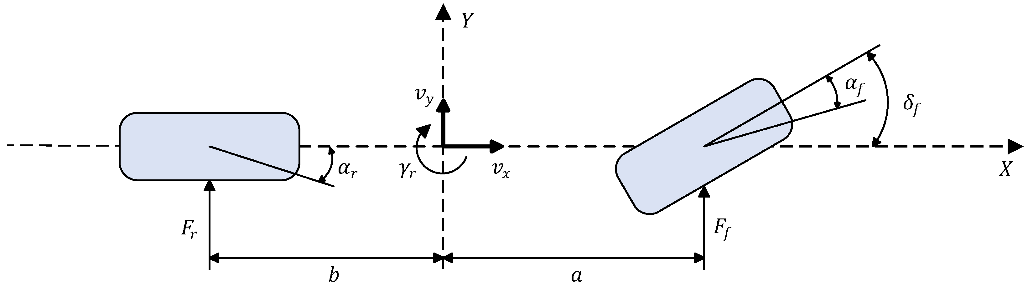
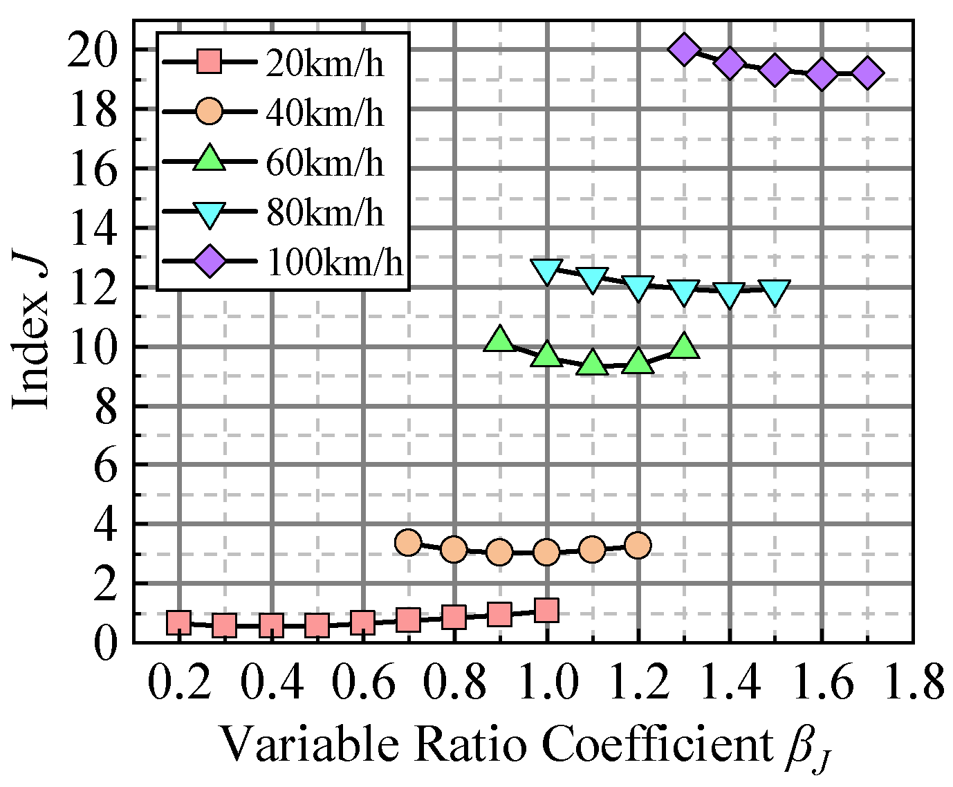
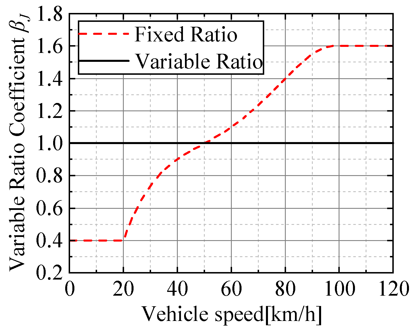
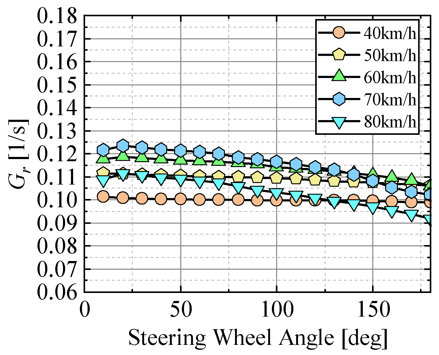
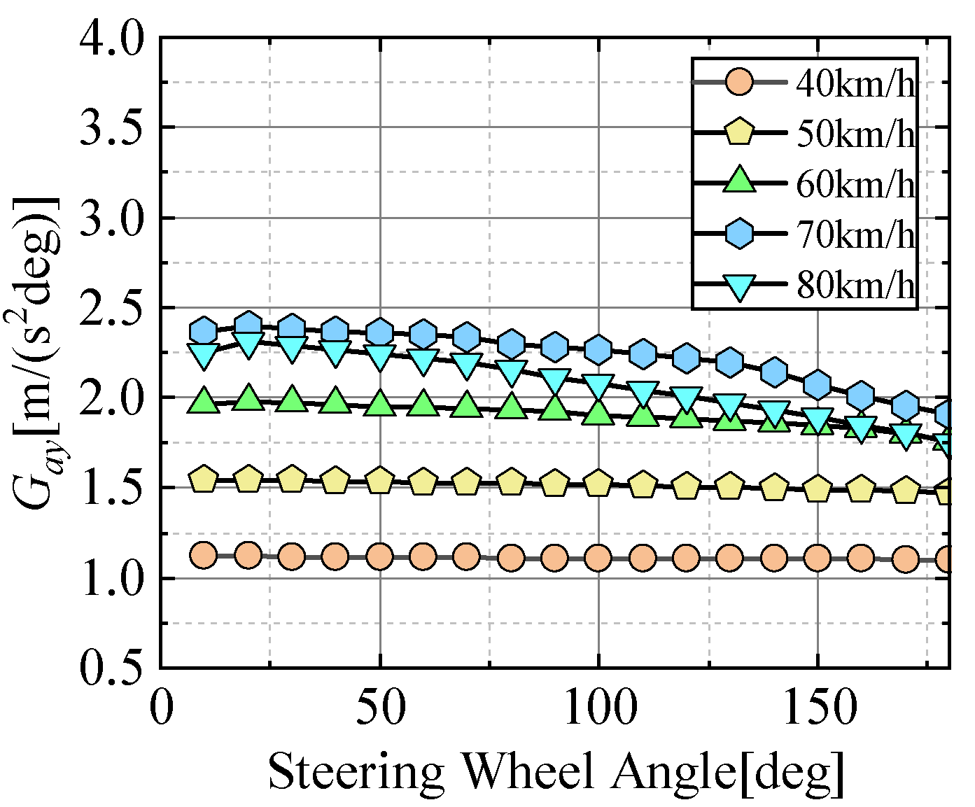
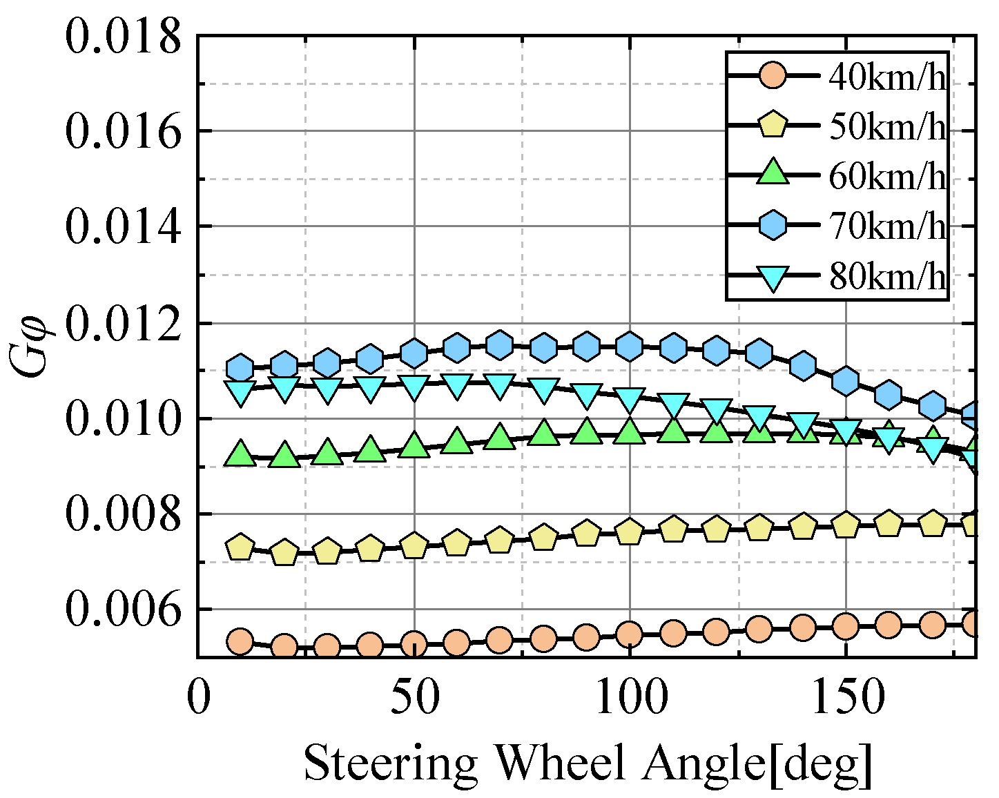
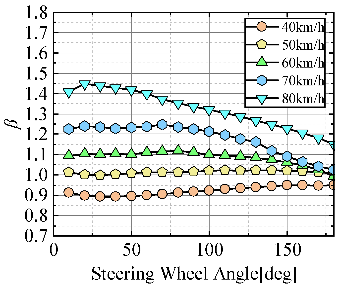
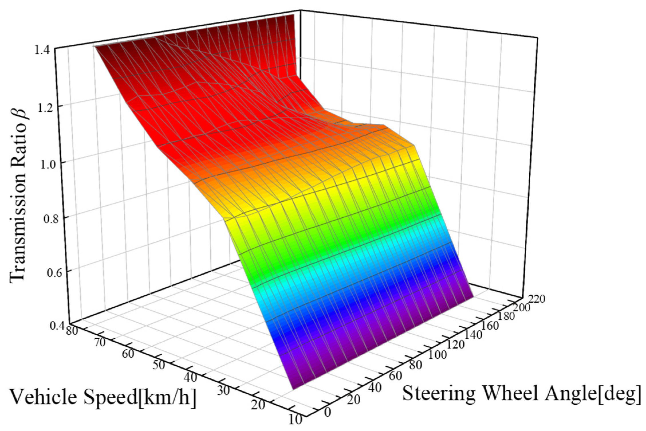
3.2. Based on the Vehicle Steering Gain

Throughout the vehicle steering process, the yaw rate gain G r , the lateral acceleration gain G a y , and the roll angle gain G φ significantly influence the maneuverability and safety of the vehicle. These gains are specifically defined concerning the steering wheel angle, as expressed below:
G r = ω θ s w
G a y = a y θ s w
G φ = φ θ s w
In order to investigate the properties of vehicle steering gain, we conducted an angular step input test at a fixed vehicle speed. The simulation results for yaw rate gain, lateral acceleration gain, and roll angle gain are depicted in Figure 5, Figure 6 and Figure 7.
Figure 5, Figure 6 and Figure 7 illustrate the characteristics of vehicle steering gain under a fixed steering ratio. It can be observed that as the steering wheel angle increases, the yaw rate gain of the vehicle decreases, the lateral acceleration gain also decreases, and the roll angle gain initially increases and then decreases. Furthermore, as the vehicle speed increases, the decline in steering gain becomes more noticeable. This acceleration is attributed to the tires entering the nonlinear region more swiftly, resulting in diminished maneuverability across a broad spectrum of steering angles. To improve the vehicle handling performance, a variable transmission ratio coefficient is utilized to ensure that the vehicle’s steering gain remains relatively consistent concerning the steering wheel angle. Examination of Figure 5, Figure 6 and Figure 7 reveals a consistent gain at small angles. Hence, this gain is chosen as the desired steering gain G r _ d e s , G a y _ d e s , G φ _ d e s corresponding to the specific vehicle speed.
The mechanical linkage between the steering actuator and the front wheels allows for the extraction of the intrinsic steering gain response through an angular step input test. The yaw rate gain G r p , the lateral acceleration gain G a y p and the roll angle gain G φ p are defined with respect to the steering actuator angle as follows:
G r p = ω δ p
G a y p = a y δ p
G φ p = φ δ p
Consequently, the variable transmission ratio coefficient, determined by the yaw rate gain, is expressed as follows:
β ω = G r p G r _ d e s
The variable transmission ratio coefficient derived from lateral acceleration gain is as follows:
β a y = G a y p G a y _ d e s
The variable transmission ratio coefficient, determined by the roll angle gain, is as follows:
β φ = G φ p G φ _ d e s
Considering the substantial influence of the yaw rate gain, lateral acceleration gain, and roll angle gain on the handling stability and safety of the vehicle, particularly in the context of large buses, these three gains are deemed critical in the vehicle steering process. Consequently, employing the coefficient of variation method to derive variable transmission ratio coefficients based on steering gain, β J is utilized to ascertain the coefficients for the three variables β ω , β a y and β φ :
V i = σ i x ¯ i
In the equation, V i represents the coefficient of variation, σ i denotes the standard deviation, x ¯ i signifies the mean value, and i corresponds to ω , a y , φ . Subsequently, using Equation (25), the weight coefficients are established:
w i = V i V ω + V a y + V φ
Using the previously described design method, the weight coefficients can vary with both vehicle speed and steering wheel angle. The overall steering gain produces the variable transmission ratio coefficients as follows:
β = w ω β ω + w a y β a y + w φ β φ
In the equation, w ω , w a y , and w φ represent the weight coefficients.
Figure 8 illustrates the variation characteristics of the variable steering ratio coefficients based on the ideal yaw angular velocity gain, ideal lateral acceleration gain, and ideal roll angle gain at a fixed vehicle speed. By adjusting the variable steering ratio coefficients, the response of the vehicle’s posture remains relatively stable, thereby enhancing the handling performance of the steer-by-wire system.

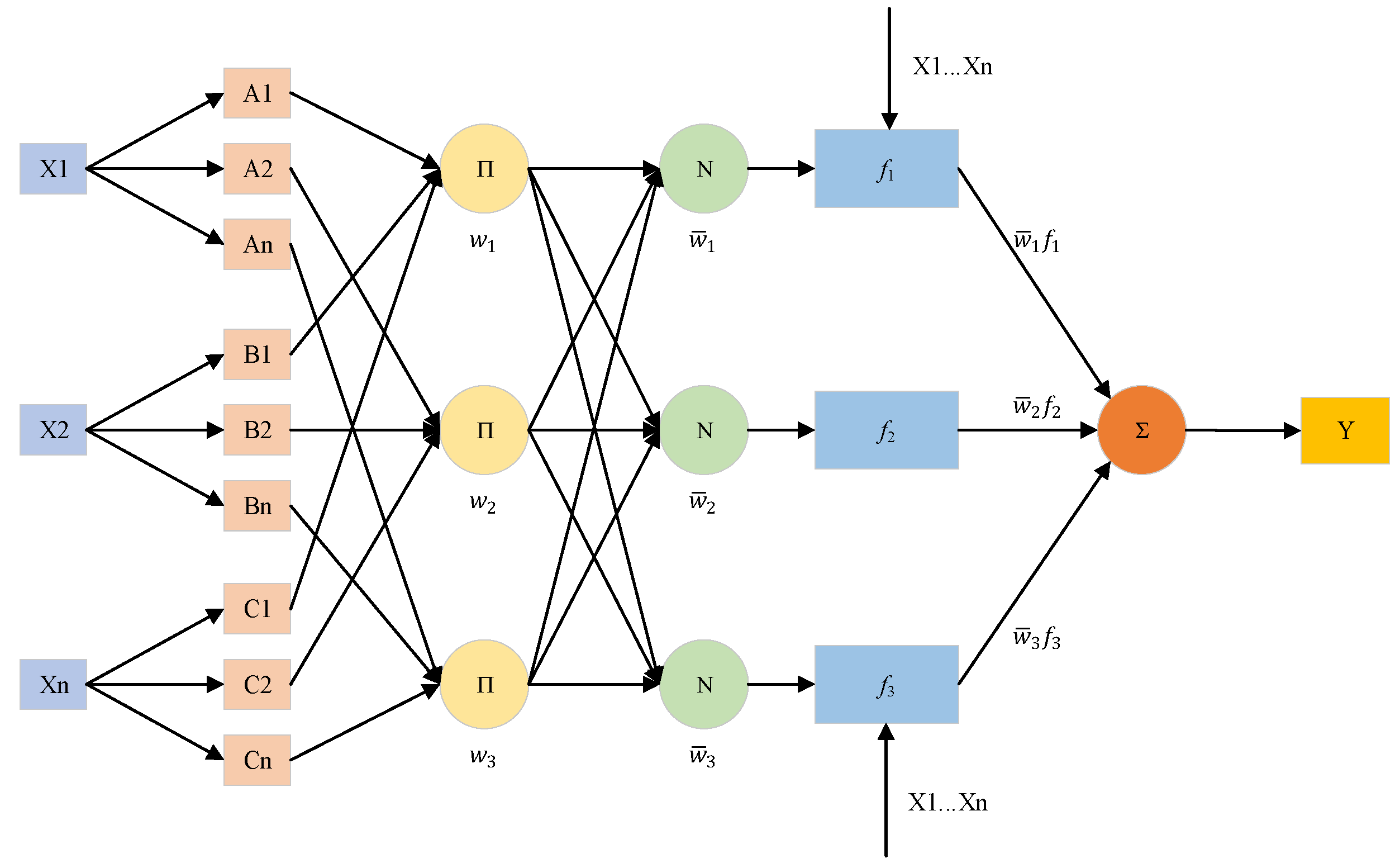
3.3. Fuzzy Neural Network Controller

The fuzzy neural network (FNN) represents an intelligent control approach that integrates fuzzy logic and neural networks to model and control nonlinear systems [30,31]. FNNs can accurately approximate both linear and nonlinear data with arbitrary precision [32,33]. This method is characterized by high accuracy, robustness, short convergence time, and a low demand for training samples [34,35]. Figure 9 illustrates a typical FNN structure, with a description of its five layers provided below.
The initial layer is the input node layer. This layer’s purpose is to conduct fuzzification on the input variables. Each node possesses a node function, and the node function of the nth node is a quadratic function, as depicted in the following formula:
μ x = 1 1 + x c a 2 b
In the equation, x denotes the node input, and a , b and c represent distinct membership functions in the fuzzy set. The output function is given by:
O i 1 x 1 = μ A i x 1 , i = 1,2 , n O j 1 x 2 = μ B j x 2 , i = 1,2 , n O k 1 x n = μ C k x n , i = 1,2 , n
In the equation, x 1 , x 2 , , x n represent node inputs, indicating the degree to which they pertain to the fuzzy variables A i , B j , C k .
The second layer is the rule node layer. The nodes in this layer are stationary nodes represented by the cumulative product symbol Π . The input to this layer is the product of all input signals to this layer.
O i 2 = w i = μ A i x 1 μ B i x 2 μ C i x n , i = 1,2 , n
The third layer is the average node layer. The nodes’ output is the ratio of each node’s excitation strength to the total sum of excitation strengths in the rule base. This ratio is applied to normalize the rule strengths.
O i 3 = w ¯ i = w i w 1 + w 2 + + w n , i = 1,2 , n
The fourth layer represents the conclusion node layer. The output of the nodes in this layer is given by:
O i 4 = w ¯ i f i = w ¯ i ( p i x 1 + q i x 2 + r i ) , i = 1,2 , n
where p i , q i and r i are consequent parameters, and f i represents the product of these consequent parameters and the system inputs.
The fifth layer represents the output node layer. The output of the nodes in this layer is given by:
O i 5 = f = i = 1 n w ¯ i f i = i = 1 n w i f i i = 1 n w i , i = 1,2 , n
Following the fuzzification of input variables, fuzzy quantities for the output variables are generated using a combination of fuzzy rules and neural networks. The final physical quantity is obtained through a process known as defuzzification. Neural networks are employed to fine-tune the parameters of the fuzzy rules.
Consequently, the chosen input parameters are the longitudinal velocity of the vehicle and the steering wheel angle. The output parameter is the variable transmission ratio coefficient. The proposed fuzzy logic estimator in this paper is generated using the FNN toolbox in Matlab R2021a. The number of iterations is set to 50,000, and the termination criteria are defined as an error less than 0.001. The neural network is generated and trained using the specified input data as described earlier. Figure 10 illustrates the results after training the variable transmission ratio coefficient.

4. Simulation and Analysis

To evaluate the effectiveness of the proposed control strategy, simulation experiments were carried out involving a human–vehicle system. The steering performance was compared between the variable transmission ratio coefficient and the fixed transmission ratio coefficient ( β   = 1).

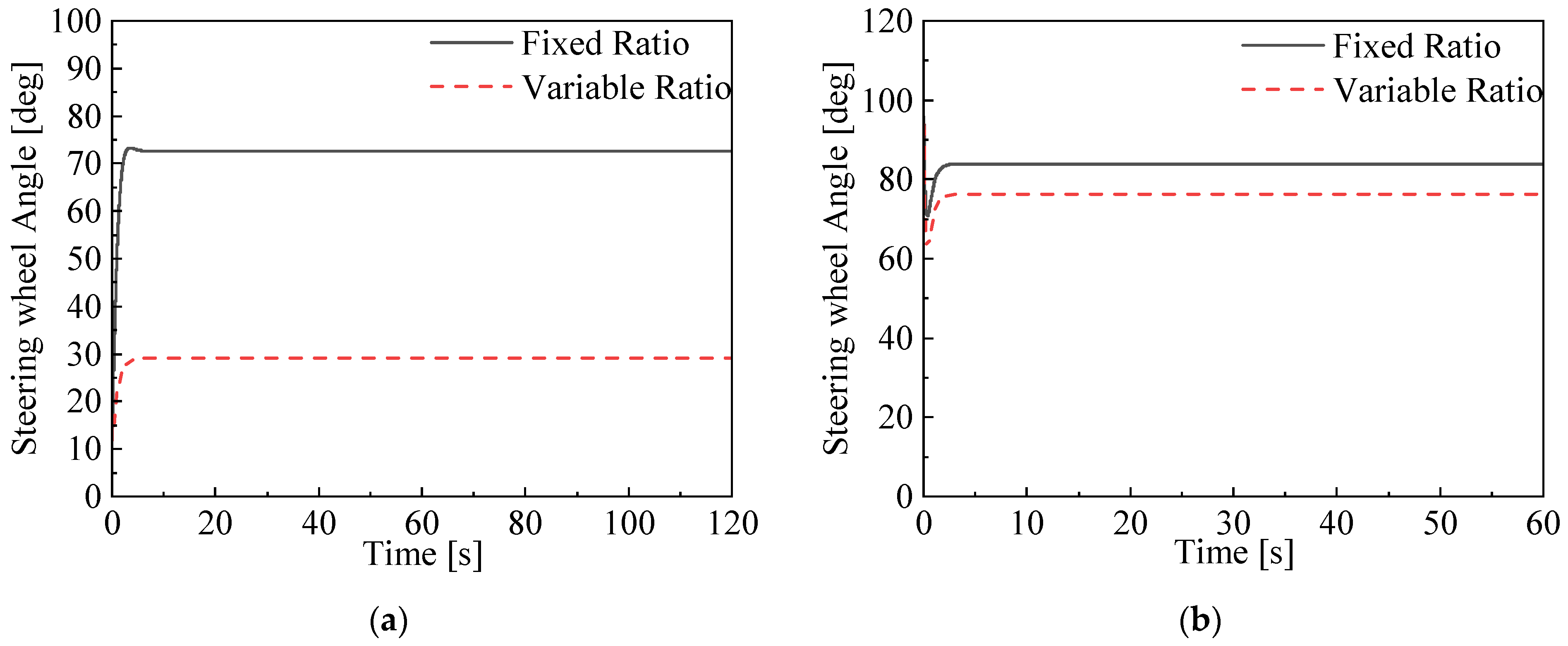
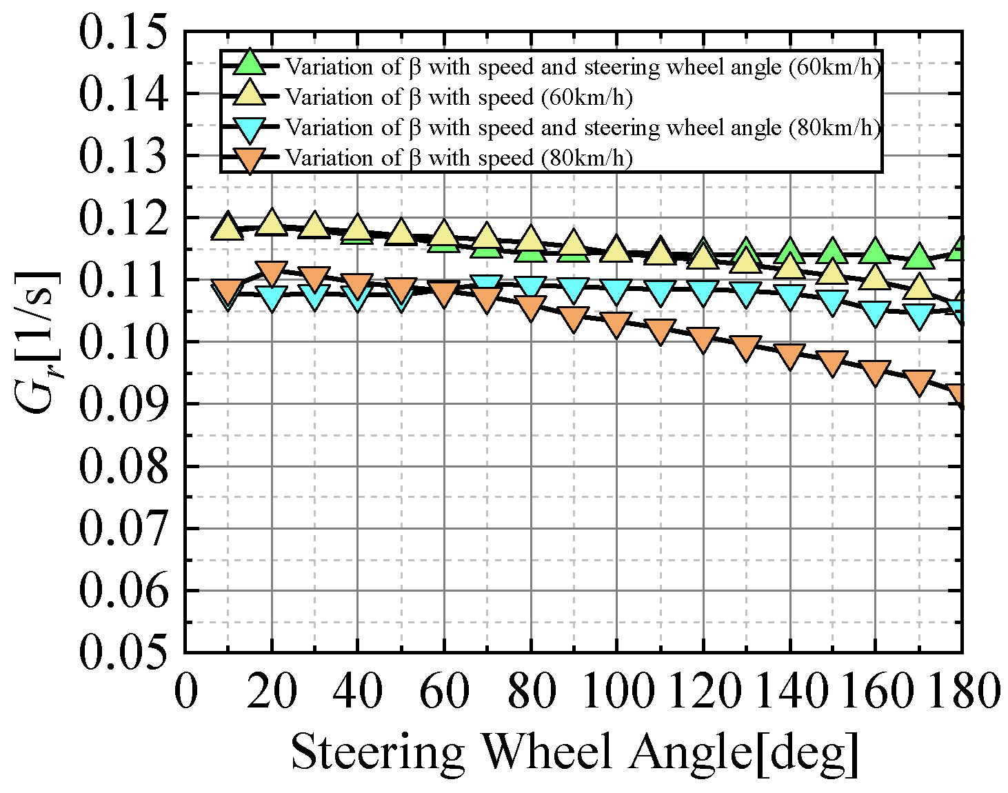
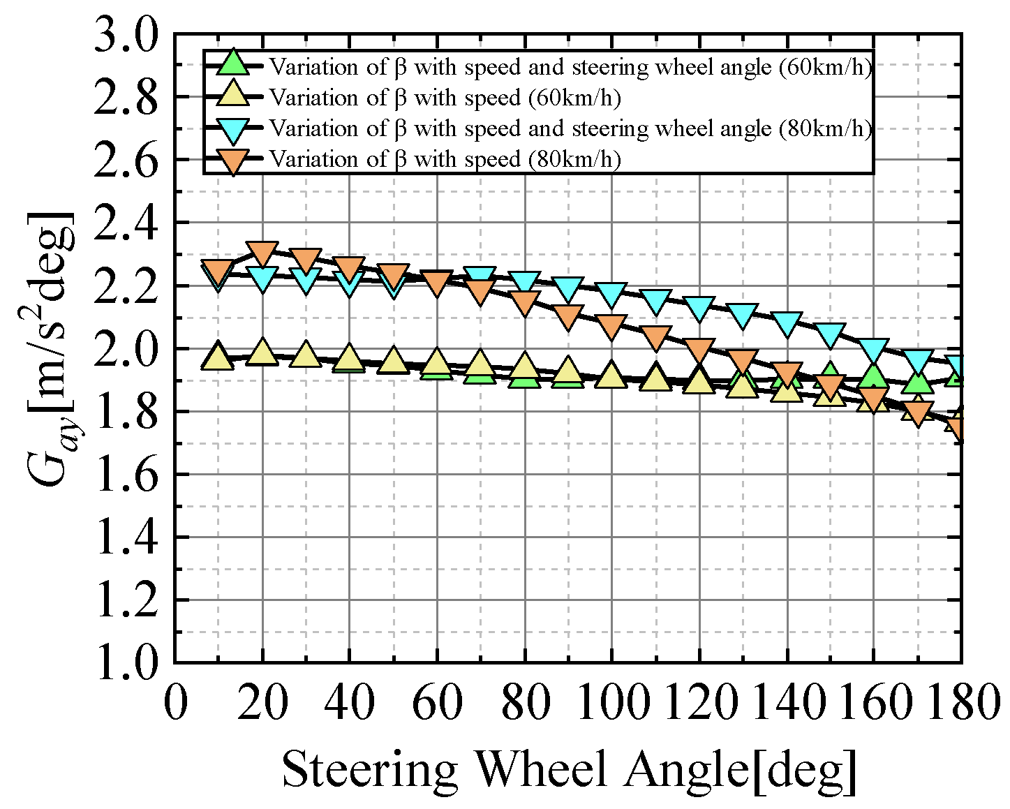
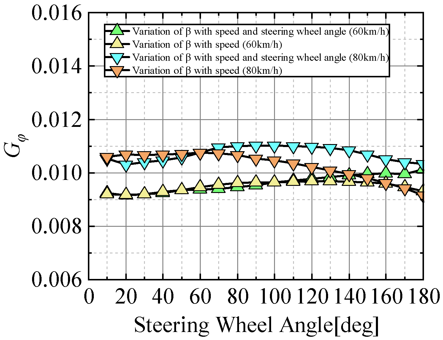
4.1. Steady-State Circle Test

Steady-state circle tests were performed to assess the vehicle’s steering performance while following a predetermined route. Figure 11 displays the simulation results of the steady-state circle test. Vehicle speeds were set to 20 km/h and 40 km/h, with a road surface coefficient of adhesion of 0.85. An analysis was conducted on the steering wheel angle inputs.
The steering wheel angle input for the steady-state circle test is illustrated in Figure 11. Simulation experiments reveal that variable transmission ratio control effectively reduces the amplitude of the vehicle’s steering wheel angle. Results in Table 2 demonstrate that at a speed of 20 km/h, the variable transmission ratio system reduces the steady-state steering wheel angle by 60% compared to the fixed transmission ratio system. At a speed of 40 km/h, the steady-state steering wheel angle decreases by 9%. Hence, the variable transmission ratio control in the steer-by-wire system can alleviate the operational burden on the driver and enhance the vehicle’s maneuverability.

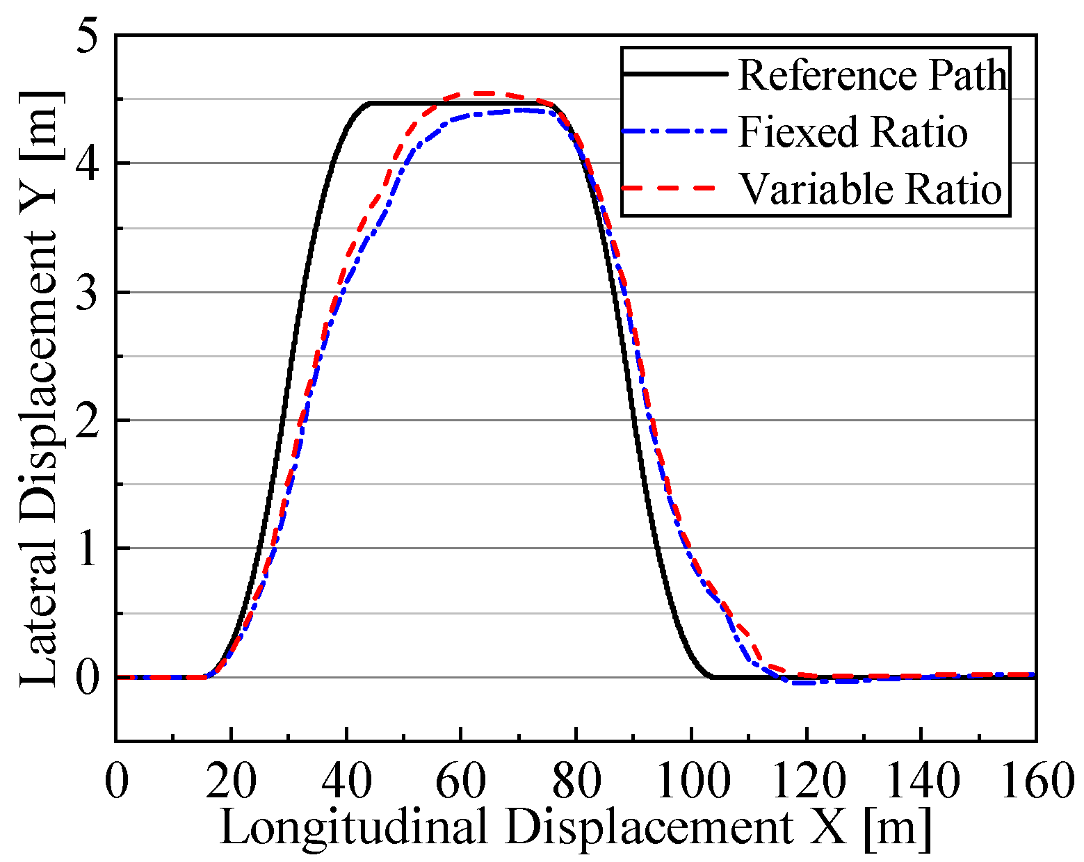
4.2. Double Lane-Change Test

To assess the vehicle handling performance of the variable transmission ratio control at relatively high speeds, a double lane-change test was conducted to evaluate the steering performance of the SBW bus. The test was conducted with a vehicle speed of 80 km/h and a road adhesion coefficient of 0.85. The simulation results are presented in Figure 12.
Figure 12 illustrates the vehicle trajectory under the experimental conditions, depicting the predetermined reference path, the vehicle trajectory under the variable transmission ratio system, and the vehicle trajectory under the fixed transmission ratio system. Table 3 presents the recorded steering control evaluation metrics for both variable and fixed transmission ratios. By combining the information presented in Figure 12 and Table 3, improvements are observed in the performance of the angular velocity metric, lateral acceleration metric, and roll angle metric. This suggests that the controller has traded off a portion of the lateral error performance metric to enhance the overall evaluation index performance. The findings further reveal that the evaluation metrics for the SBW system with variable transmission ratio control are consistently smaller than those of the fixed transmission ratio system. This substantiates the claim that variable transmission ratio control contributes to the enhanced maneuverability and safety of the vehicle.

4.3. Angular Step Test

To validate the effectiveness of the variable transmission ratio control technology in modifying the vehicle’s steering gains, a step angle input test was conducted to assess the yaw rate gain, lateral acceleration gain, and roll angle gain. The road adhesion coefficient was set at 0.85, with vehicle speeds fixed at 60 km/h and 80 km/h. The simulation results are depicted in Figure 13, Figure 14 and Figure 15.
The experimental results of the vehicle’s yaw rate gain, lateral acceleration gain, and roll angle gain in the angle step input test at different speeds are depicted in Figure 13, Figure 14 and Figure 15. At a speed of 60 km/h, the vehicle’s steering gain under fixed transmission ratio control starts to decrease when the steering wheel angle reaches 120 degrees. At a speed of 80 km/h, the vehicle’s steering gain under fixed transmission ratio control starts to decrease prematurely at a steering wheel angle of 60 degrees. Conversely, the variable transmission ratio control technology effectively maintains yaw rate gain, lateral acceleration gain, and roll angle gain, thereby improving the driver’s maneuvering comfort.

5. Conclusions

Leveraging the characteristics of steer-by-wire angle transmission, we designed a variable transmission ratio controller that integrates objective evaluation metrics and vehicle steering gains. The controller is intended to enhance the maneuvering stability and safety of SBW vehicles. The relationship between the variable transmission ratio coefficient and vehicle speed is determined using multi-objective evaluation metrics. The mapping relationship between the variable transmission ratio coefficient and steering wheel angle is established by maintaining the yaw rate gain, lateral acceleration gain, and roll angle gain. Subsequently, a coefficient fusion method utilizing the coefficient of variation is employed to integrate the three steering gains into a variable transmission ratio coefficient. Finally, a fuzzy neural network is employed to obtain a nonlinear controller with the vehicle speed and steering wheel angle as inputs and the variable transmission ratio coefficient as the output. To validate the proposed control strategy’s performance, various tests were conducted. In the steady-state circle test, the reduction in the required steering angle proves that there was a decrease in the steering burden on the driver. The discernible variance in steering angle alteration aligns with the design principle of achieving light steering at low speeds and ensuring stability during high-speed steering. Variable transmission ratio control is effective in improving the performance of the combined evaluation metrics in the double lane-change test and in maintaining constant steering gain in the angular step test. The results demonstrate that the proposed variable transmission ratio controller not only reduces the driver’s operational burden but also enhances the maneuvering stability and safety of the vehicle.
In future research, improved driver steering models will be integrated into a simulation environment to enhance feedback accuracy regarding the handling comfort of the SBW vehicle. Advanced algorithms will be applied to optimize the relationship between the ratio coefficients and vehicle speed. The road friction coefficient, a key factor affecting the steering control of the vehicle, is also taken into account in the controller design. Furthermore, additional vehicle experiments and evaluations will be conducted to further validate the proposed control strategy.

Author Contributions

Conceptualization, J.L. and F.Z.; methodology, J.L. and F.Z.; software, L.S., G.S. and Z.L.; validation, F.Z., Y.Z. and L.S.; formal analysis, J.L.; investigation, L.S. and G.S.; resources, J.L. and F.Z.; data curation, F.Z. and J.L.; writing—original draft preparation, J.L.; writing—review and editing, F.Z. and J.L.; visualization, J.L.; supervision, F.Z.; project administration, F.Z.; funding acquisition, F.Z. and L.S. All authors have read and agreed to the published version of the manuscript.

Funding

This research was supported by the National Key Research and Development Program of China (2021YFB2500704).

Data Availability Statement

Data are contained within the article.

Acknowledgments

The authors would like to thank the editors and the anonymous reviewers for their comments and suggestions.

Conflicts of Interest

The authors declare no conflicts of interest.

References

  1. Su, J.; Lou, J.; Jiang, X. Overview of intelligent vehicle core technology and development. IOP Conf. Ser. Earth Environ. Sci. 2021, 769, 042054. [Google Scholar] [CrossRef]
  2. Jiangxue, C.; Manjiang, L.; Xuefeng, B. The Development of Engineering Vehicles Steer—By-Wire System. In Proceedings of the 3rd International Conference on Material, Mechanical and Manufacturing Engineering, Guangzhou, China, 27–28 June 2015; pp. 1763–1766. [Google Scholar]
  3. Shao, W.; Liang, X.; Fang, T.; Zhao, L.; Hu, Y. Active steering stability control of steer-by-wire vehicles based on variable horizon-robust model predictive control. J. Braz. Soc. Mech. Sci. Eng. 2023, 45, 410. [Google Scholar] [CrossRef]
  4. Wei, H.; Wang, J.; Jian, M.; Mei, S.; Huang, M. Steer-by-Wire Control System Based on Carsim and Simulink. In Proceedings of the 2021 IEEE International IOT, Electronics and Mechatronics Conference (IEMTRONICS), Toronto, ON, Canada, 21–24 April 2021; pp. 1–5. [Google Scholar]
  5. Cho, J.; Huh, K. Active Front Steering for Driver’s Steering Comfort and Vehicle Driving Stability. Int. J. Automot. Technol. 2019, 20, 589–596. [Google Scholar] [CrossRef]
  6. Husain, S.S.; Al-Dujaili, A.Q.; Jaber, A.A.; Humaidi, A.J.; Al-Azzawi, R.S. Design of a Robust Controller Based on Barrier Function for Vehicle Steer-by-Wire Systems. World Electr. Veh. J. 2024, 15, 17. [Google Scholar] [CrossRef]
  7. Irmer, M.; Degen, R.; Nüßgen, A.; Thomas, K.; Henrichfreise, H.; Ruschitzka, M. Development and Analysis of a Detail Model for Steer-by-Wire Systems. IEEE Access 2023, 11, 7229–7236. [Google Scholar] [CrossRef]
  8. Shi, G.B.; Guo, C.; Wang, S.; Liu, T.Y. Angle Tracking and Fault-Tolerant Control of Steer-by-Wire System with Dual Three-Phase Motor for Autonomous Vehicle. IEEE Trans. Intell. Transp. Syst. 2023, 1–12. [Google Scholar] [CrossRef]
  9. Wang, Y.; Ma, B.; Wang, D.; Chai, T. Event-Triggered Prespecified Performance Control for Steer-by-Wire Systems with Input Nonlinearity. IEEE Trans. Intell. Transp. Syst. 2023, 24, 6922–6931. [Google Scholar] [CrossRef]
  10. Mortazavizadeh, S.A.; Ghaderi, A.; Ebrahimi, M.; Hajian, M. Recent Developments in the Vehicle Steer-by-Wire System. IEEE Trans. Transp. Electrif. 2020, 6, 1226–1235. [Google Scholar] [CrossRef]
  11. Fahami, S.M.H.; Zamzuri, H.; Mazlan, S.A.; Zakaria, M.A. Modeling and simulation of vehicle steer by wire system. In Proceedings of the 2012 IEEE Symposium on Humanities, Science and Engineering Research, Kuala Lumpur, Malaysia, 24–27 June 2012; pp. 765–770. [Google Scholar]
  12. Krishna, S.; Narayanan, S.; Denis Ashok, S. Fuzzy logic based yaw stability control for active front steering of a vehicle. J. Mech. Sci. Technol. 2014, 28, 5169–5174. [Google Scholar] [CrossRef]
  13. Azzalini, M.; Gissinger, G.L.; Boussouar, V.; Coutant, P. Computation of a variable steering ratio with a fuzzy logic method. In Proceedings of the Intelligent Vehicle Symposium, Versailles, France, 17–21 June 2002; Volume 251, pp. 259–267. [Google Scholar]
  14. Bianchi, D.; Borri, A.; Benedetto, M.D.D.; Gennaro, S.D. Active Attitude Control of Ground Vehicles with Partially Unknown Model. IFAC-PapersOnLine 2020, 53, 14420–14425. [Google Scholar] [CrossRef]
  15. Yang, H.; Liu, W.; Chen, L.; Yu, F. An adaptive hierarchical control approach of vehicle handling stability improvement based on Steer-by-Wire Systems. Mechatronics 2021, 77, 102583. [Google Scholar] [CrossRef]
  16. Zhang, Y.; Xiao, C.; Chen, J.; Yu, X.; Jing, S. Research on Logic Control of Variable Transmission Ratio SBW based on Pan-Boolean Algebra. In Proceedings of the 2021 International Conference on Robotics and Control Engineering, Tokyo, Japan, 23 April 2021; pp. 54–58. [Google Scholar]
  17. Zhai, P.; Du, H.; Li, Z. Bilateral control of vehicle Steer-by-Wire system with variable gear-ratio. In Proceedings of the 2013 IEEE 8th Conference on Industrial Electronics and Applications (ICIEA), Melbourne, VIC, Australia, 19–21 June 2013; pp. 811–815. [Google Scholar]
  18. Zhang, Q.Y.; Lin, W.P.; Wang, Y.R.; Wu, X.J.; Luo, Y.J. Control Strategy of the Vehicle’s Active Steer by Wire. J. Coast. Res. 2020, 103, 355–360. [Google Scholar] [CrossRef]
  19. Fang, L.; Lifang, W.; Chenglin, L.; Yan, W. Active steering control strategy of steer-by-wire system based on variable steering ratio. In Proceedings of the 2014 IEEE Conference and Expo Transportation Electrification Asia-Pacific (ITEC Asia-Pacific), Beijing, China, 31 August–3 September 2014; pp. 1–5. [Google Scholar]
  20. Liu, Z.; Xu, X.; Xie, J.; Wang, F.; Su, P. Variable transmission ratio design of a steer-by-wire system for intelligent vehicles. Proc. Inst. Mech. Eng. Part C J. Mech. Eng. Sci. 2022, 236, 9341–9353. [Google Scholar] [CrossRef]
  21. Zou, S.; Luan, Z.; Zhao, W.; Wang, C. Personalized design strategy of vehicle steer-by-wire characteristics considering driving style. Proc. Inst. Mech. Eng. Part C J. Mech. Eng. Sci. 2023, 237, 253–266. [Google Scholar] [CrossRef]
  22. Yu, H.; Güvenç, L.; Özgüner, Ü. Heavy duty vehicle rollover detection and active roll control. Veh. Syst. Dyn. 2008, 46, 451–470. [Google Scholar] [CrossRef]
  23. Hu, C.; Wang, Z.; Qin, Y.; Huang, Y.; Wang, J.; Wang, R. Lane Keeping Control of Autonomous Vehicles with Prescribed Performance Considering the Rollover Prevention and Input Saturation. IEEE Trans. Intell. Transp. Syst. 2020, 21, 3091–3103. [Google Scholar] [CrossRef]
  24. Yang, X.; Wu, C.; He, Y.; Lu, X.Y.; Chen, T. A Dynamic Rollover Prediction Index of Heavy-Duty Vehicles with a Real-Time Parameter Estimation Algorithm Using NLMS Method. IEEE Trans. Veh. Technol. 2022, 71, 2734–2748. [Google Scholar] [CrossRef]
  25. Tian, Y.; Yao, Q.; Wang, C.; Wang, S.; Liu, J.; Wang, Q. Switched model predictive controller for path tracking of autonomous vehicle considering rollover stability. Veh. Syst. Dyn. 2022, 60, 4166–4185. [Google Scholar] [CrossRef]
  26. Prakash, R.; Dheer, D.K. Evolutionary Algorithms Based Model Predictive Control for Vehicle Lateral and Roll Motion Control. Arab. J. Sci. Eng. 2023, 48, 6857–6871. [Google Scholar] [CrossRef]
  27. Ding, X.; Wang, Z.; Zhang, L.; Liu, J. A Comprehensive Vehicle Stability Assessment System Based on Enabling Tire Force Estimation. IEEE Trans. Veh. Technol. 2022, 71, 11571–11588. [Google Scholar] [CrossRef]
  28. Zhao, W.; Wang, A.; Zou, S.; Zhang, H. Individual Auxiliary and Fault-Tolerant Control of Steer-by-Wire System Considering Different Drivers Steering Characteristics. IEEE/ASME Trans. Mechatron. 2021, 26, 1558–1569. [Google Scholar] [CrossRef]
  29. Wang, J.; Wang, H.; Jiang, C.; Cao, Z.; Man, Z.; Chen, L. Steering Feel Design for Steer-by-Wire System on Electric Vehicles. In Proceedings of the 2019 Chinese Control Conference (CCC), Guangzhou, China, 27–30 July 2019; pp. 533–538. [Google Scholar]
  30. Foroughi, B.; Nhan, P.V.; Iranmanesh, M.; Ghobakhloo, M.; Nilashi, M.; Yadegaridehkordi, E. Determinants of intention to use autonomous vehicles: Findings from PLS-SEM and ANFIS. J. Retail. Consum. Serv. 2023, 70, 103158. [Google Scholar] [CrossRef]
  31. Selma, B.; Chouraqui, S.; Selma, B.; Abouaïssa, H. ANFIS controller design based on pigeon-inspired optimization to control an UAV trajectory tracking task. Iran J. Comput. Sci. 2021, 4, 1–16. [Google Scholar] [CrossRef]
  32. Karaboga, D.; Kaya, E. Adaptive network based fuzzy inference system (ANFIS) training approaches: A comprehensive survey. Artif. Intell. Rev. 2019, 52, 2263–2293. [Google Scholar] [CrossRef]
  33. Kumar, S.Y.V.; Mukku, M.; Jonnalagadda, V.K.; Gudidh, A.; Mukku, M.; Kumar, P. Speed Control Analysis of an Electrical Vehicle by Using Fuzzy- PID and ANFIS Controllers. In Proceedings of the 2022 3rd International Conference on Communication, Computing and Industry 4.0 (C2I4), Bangalore, India, 15–16 December 2022; pp. 1–6. [Google Scholar]
  34. George, M.A.; Kamat, D.V.; Kurian, C.P. Electric vehicle speed tracking control using an ANFIS-based fractional order PID controller. J. King Saud Univ. Eng. Sci. 2022. [Google Scholar] [CrossRef]
  35. Krishna, S.; Ashok, S.D.; Narayanan, S. ANFIS-based active front steering system for reducing yaw disturbance of a vehicle using steer-by-wire system. Int. J. Dyn. Control 2023. [Google Scholar] [CrossRef]
Figure 1. Structure of the steer-by-wire system for commercial vehicle.
Actuators 13 00048 g001
Figure 2. The linear 2-DOF model.
Actuators 13 00048 g002
Figure 3. Simulation results for the comprehensive evaluation indicators.
Actuators 13 00048 g003
Figure 4. Characteristics of the variable steering ratio coefficient based on comprehensive evaluation indicators.
Actuators 13 00048 g004
Figure 5. At a specific vehicle speed with a fixed steering ratio, the relationship between the yaw rate gain characteristic and different steering wheel angles.
Actuators 13 00048 g005
Figure 6. At a specific vehicle speed with a fixed steering ratio, the relationship between the lateral acceleration gain characteristic and different steering wheel angles.
Actuators 13 00048 g006
Figure 7. At a specific vehicle speed with a fixed steering ratio, the relationship between the roll angle gain characteristic and different steering wheel angles.
Actuators 13 00048 g007
Figure 8. At a fixed steering ratio and specific vehicle speed, the relationship between the integrated steering gain characteristics and different steering wheel angles.
Actuators 13 00048 g008
Figure 9. FNN diagram of the structure.
Actuators 13 00048 g009
Figure 10. Fuzzy neural network output surface.
Actuators 13 00048 g010
Figure 11. Simulation results of the steady-state circle test: (a) 20 km/h working condition; (b) 40 km/h working condition.
Actuators 13 00048 g011
Figure 12. Vehicle trajectory in the double lane-change test.
Actuators 13 00048 g012
Figure 13. The influence of transmission ratio on yaw rate gain.
Actuators 13 00048 g013
Figure 14. The influence of transmission ratio on lateral acceleration gain.
Actuators 13 00048 g014
Figure 15. The influence of transmission ratio on roll angle gain.
Actuators 13 00048 g015
Table 1. Vehicle model parameters.
ParametersValue
The vehicle mass m (kg)7620
The distances from the center of gravity to the front axle a (m)3.105
The distances from the center of gravity to the rear axle b (m)1.385
The moment of inertia of the vehicle about the z -axis I z (kgm2)30,782
The lateral stiffness of the front wheels C f (kN/rad)230,390.74
The lateral stiffness of the rear wheels C r (kN/rad)434,846.78
Table 2. Maximum steering wheel angle in the steady-state circle test.
Maximum Steering Wheel Angle (deg)Fixed RatioVariable Ratio
20 km/h72.6229.08
40 km/h83.8976.21
Table 3. Comparison of comprehensive evaluation metrics.
Evaluation MetricsFixed RatioVariable Ratio
Comprehensive Evaluation10.5810.42
Lateral Error Metric0.32420.3355
Angular Velocity Metric22.2521.89
Lateral Acceleration Metric8.0217.938
Roll Angle Metric0.92950.9285
Disclaimer/Publisher’s Note: The statements, opinions and data contained in all publications are solely those of the individual author(s) and contributor(s) and not of MDPI and/or the editor(s). MDPI and/or the editor(s) disclaim responsibility for any injury to people or property resulting from any ideas, methods, instructions or products referred to in the content.

