Article

Clamping Force Control Strategy of Electro-Mechanical Brake System Using VUF-PID Controller

Key Laboratory of Conveyance and Equipment Ministry of Education, East China Jiaotong University, Nanchang 330000, China
*
Author to whom correspondence should be addressed.
Actuators 2023, 12(7), 272; https://doi.org/10.3390/act12070272
Submission received: 17 May 2023 / Revised: 27 June 2023 / Accepted: 28 June 2023 / Published: 3 July 2023
(This article belongs to the Special Issue Actuators and Control of Intelligent Electric Vehicles)

Abstract

:
Clamping force control is one of the key technologies in the algorithm design and implementation of electro-mechanical braking system, whose control effects directly affect the vehicle braking performance and safety performance. In order to improve the clamping force control performance of electro-mechanical braking (EMB) system, an EMB clamping force control method based on Variable universe adaptive fuzzy PID (VUF-PID) controller is proposed, and stretching factors are added to the fuzzy PID control. According to the operation of the controlled object, the fuzzy theory domain can be adjusted in real time to keep the system in the proper parameter value and improve the adaptive ability of the system. The response characteristics and effectiveness of clamping force under step braking condition, gear switching braking condition and sine braking condition are verified by simulation experiments using MATLAB/Simulink. The results show that the proposed VUF-PID control method has strong tracking characteristics and stability characteristics, and meet the braking requirements under different braking conditions.

1. Introduction

With the development of the industrial, technological innovation and energy consumption continues to accelerate, the automobile industry pays more and more attention to the process of electrification and intellectualization, thus accelerating the rapid evolution of automotive electronic technology and architecture [1]. The braking system, as the key to the safety of electric vehicles, is required to realize the active braking function and energy recovery function [2]. The traditional braking system cannot adjust the braking force in real time and cannot meet the development needs of electric vehicles. Therefore, the wire-controlled dynamic technology has gradually become a research hotspot at present [3].
According to current research ideas, there are two main types of wire control dynamic systems: electro-hydraulic brake system (EHB) and electro-mechanical brake system (EMB) [4]. The EHB is a simple modification of the original traditional braking system, using a motor instead of a vacuum booster, and the braking force can be adjusted. The energy recovery function can be realized through semi-decoupling or full decoupling between the brake pedal and the brake master cylinder. Compared with EHB, EMB eliminates hydraulic components such as hydraulic master cylinder, brake pipeline, etc., with flexible structure layout, fast response speed, good compatibility, and arranged at the wheel end, can realize individual and precise control of the wheel, and can integrate multiple functional technologies, which is the main research direction of the current wire control dynamic system [5].
Because of the many advantages of EMB systems, more and more people are studying them. Krishnamurthy et al. studied EMB systems using switched reluctance motors and proposed a robust nonlinear force controller [6]. Han et al. established a mathematical model of electronic wedge brake and proposed a contact point detection algorithm based on sliding mode control [7]. Park et al. analyzed the mechanical and electrical parts of EMB [8]. Baek et al. adopted the Maximum torque per ampere (MTPA) method to control the motor current in the electro-mechanical brake, estimated the d-q axis current reference value through the motor Angle, realized the efficient control of EMB and reduced energy consumption [9].
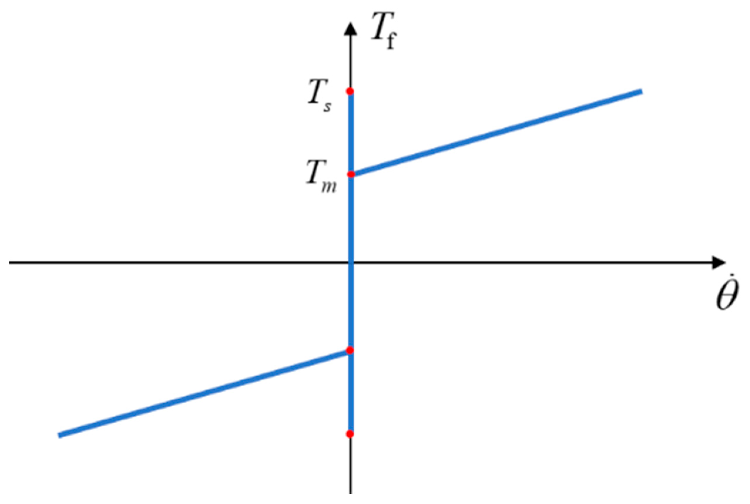
Under the action of brake saturation, load-related friction and nonlinear stiffness, the performance of EMB will be subject to many limitations [10]. How to quickly and accurately control the clamping force is the current research focus of EMB. Young et al. proposed a clamping force estimation control method based on a new type of switch to avoid excessive clamping force caused by inertia effect [11]. Considering the failure of clamping force sensor, Zhao et al. proposed a clamping force control method based on power fast terminal sliding mode [12]. Chihoon et al. proposed a clamping force control calculation based on adaptive PID considering the initial clearance of electro-mechanical brake [13]. Park et al. proposed a clamping force estimation and control method based on hysteresis model considering the clamping force phase hysteresis [14]. Lee et al. established a clamping force controller considering the optimal state constraint time based on the double-switch control method [15]. Li et al. established a nonlinear EMB model and proposed a clamping force control method considering brake clearance and force following to achieve a smooth transition between clearance elimination and clamping force following [16]. It is known that the clamping force control strategy of the existing EMB system has problems such as response hysteresis and following jitter [17].
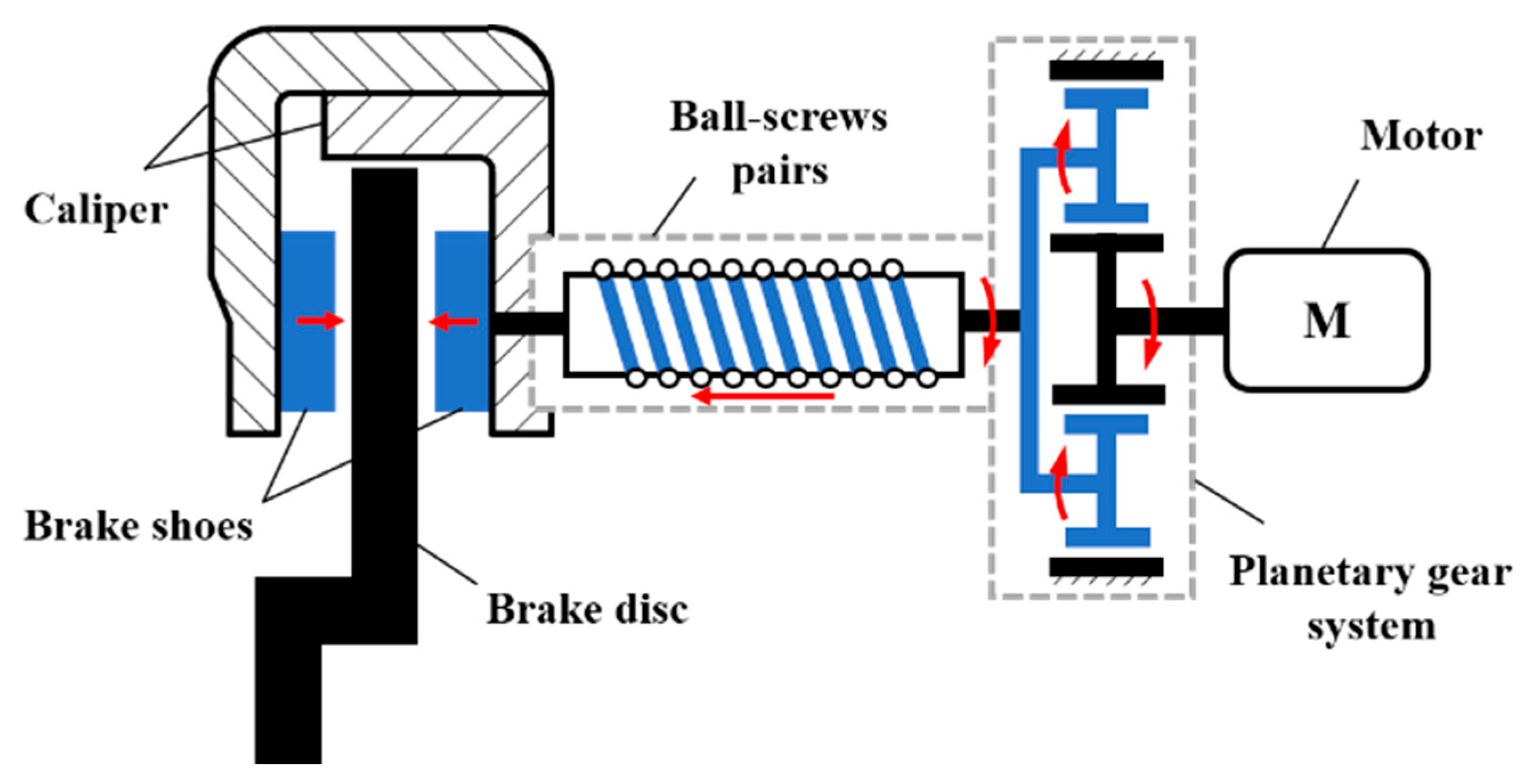
Therefore, a VUF-PID based EMB clamping force control strategy is proposed to solve the above problems in this paper. The stretching factors are introduced to adjust the EMB system in real time, so that the system can keep the proper parameter value and improve the system’s adaptive ability. There are two main contributions of this paper. First, an EMB structure with a planetary gear reducer and ball screw configuration is used, and a mathematical model of an EMB system with a new type of clamping force controller that considers the friction characteristics of the motor is developed. Secondly, an EMB clamping force control method based on VUF-PID controller is proposed, which uses stretching factors to adjust the system parameters in real time according to the running state of the controlled object.
The arrangement of this paper is as follows. In Section 2, the correlation analysis and model establishment of EMB system are carried out. In Section 3, an EMB clamping force control strategy based on VUF-PID is established. In Section 4, different working conditions are simulated to verify the effectiveness of the proposed strategy. Section 5 presents conclusions and a vision for future work.

2. Modeling of EMB

The structure of the EMB studied in this paper is mainly consists of driving motor, planetary gear reducer, ball screw mechanism, calipers and other components. The simplified schematic diagram of the EMB brake system is shown in Figure 1. The working principle of EMB is as follows: When the EMB system receives the target braking force signal from the Vehicle control unit (VCU), the driving motor starts to work, reduces the speed and increases the torque through the planetary gear reducer, converts the rotating motion into linear motion through the ball screw pair, and drives the brake linings to clamp the brake disc to produce braking torque.

2.1. Motor Model

The driving motor model of EMB system in this paper is a permanent magnet synchronous motor (PMSM) with comprehensive performance, and it is difficult to establish an accurate mathematical model due to its strongly coupled nonlinear characteristics. Therefore, it is necessary to simplify the complex mathematical model of PMSM. Assuming that the op state of the three-phase PMSM studied in this paper is in an ideal state, the stator voltage equation of the three-phase PMSM in the synchronous rotating coordinate system is given:
u d = R i d + L d d d t i d ω θ L q i q u q = R i q + L q d d t i q + ω θ ( L d i d + ψ f )
where i d , i q is the current of axis d and q, A; u d , u q is the voltage component of axis d and axis q, V; L d , L q is the inductance component of the d and q axes, H; ω θ is the electric angular velocity, rad/s.
The torque equation of three-phase PMSM in the synchronous rotation coordinate system is defined:
T e = 3 2 p n i q i d L d L q + ψ f
where T e is the electromagnetic torque of the motor, N·m; p n is the number of magnetic poles.
When the system adopts vector control of i d = 0 , there is L d = L q , the three-phase PMSM torque equation is simplified:
T e = 3 2 p n ψ f i q
The motion equation of the motor is defined:
J d ω m d t = T e T L B ω m
where J is the moment of inertia, kg·m2; T L is the load torque, N·m; B is the viscous friction coefficient, N·m (rad/s)−1; ω m is the mechanical angular velocity, rad/s.

2.2. Motor Friction Model

The motor of EMB is required to have a relatively high precision control performance, and the friction in the motor will directly affect the clamping force generated by the EMB system. Therefore, it is very important to establish an accurate motor friction model for improving the overall braking performance of the EMB system. In this paper, static friction characteristic models of static friction, Coulomb friction and viscous friction are selected. The static friction characteristic curve of the motor is shown in Figure 2, and the friction torque is given:
T f = T m ,                                                 θ ˙ = 0 , T m < T s T s sgn T m ,                   θ ˙ = 0 , T m T s T c sgn θ ˙ + B θ ˙ ,     θ ˙ 0
where θ ˙ is the relative sliding speed; T m is the external torque, N·m; T s is static friction moment, N·m; T c is the coulomb friction torque, N·m.

2.3. Transmission Mechanism Model

Due to the limitations of motor installation space, EMB system needs to be equipped with a device to reduce speed and increase torque. In order to meet the needs of braking force under different driving conditions of vehicles, the EMB motor is made to work in the high efficiency curve as much as possible. In this paper, the transmission mechanism consisting of a planetary gear reducer and a ball screw mechanism is adopted. The gear ring is fixed and the motor output shaft drives the solar wheel to rotate and transmit the torque to the ball screw mechanism changes the rotary motion into linear motion. The mathematical model of transmission mechanism is defined:
x = L 2 π i p θ m
where θ m is the Angle of the motor, rad; L is the lead of ball screw, mm; x is the screw nut displacement, mm; i p is the planetary gear ratio.

2.4. Load Model

The load torque of the motor comes from the thrust generated by the ball screw mechanism, and the brake liner generates a clamping force on the brake disc under the action of the thrust. There is a certain mathematical relationship between the clamping force of the EMB system and the shape variable of the friction disc [18], which indicates that the clamping force on the brake disc is given:
F n = A 1 s 3 + A 2 s 2 + A 3 s
where A 1 , A 2 , A 3 is the coefficient of the clamping force cubic polynomial; s is the shape variable of the friction plate, mm.
The relationship between the load torque of the motor and the clamping force transmitted is defined:
T L = F n L 2 π i p η s η p
where η s is the transmission efficiency of ball screw mechanism; η p is planetary gear transmission efficiency.

2.5. Brake Disc Model

The brake liner is installed in the caliper end, and the ball screw mechanism is used to push the brake disc to clamp, so that the left and right sides of the brake disc produce the same friction torque, which is given:
T μ = 2 F n R b μ b
where F n is the clamping force, N; μ b is the friction coefficient of the friction plate; R b is the effective radius of the brake disc, m.

3. EMB Clamping Force Control Strategy Based on VUF-PID

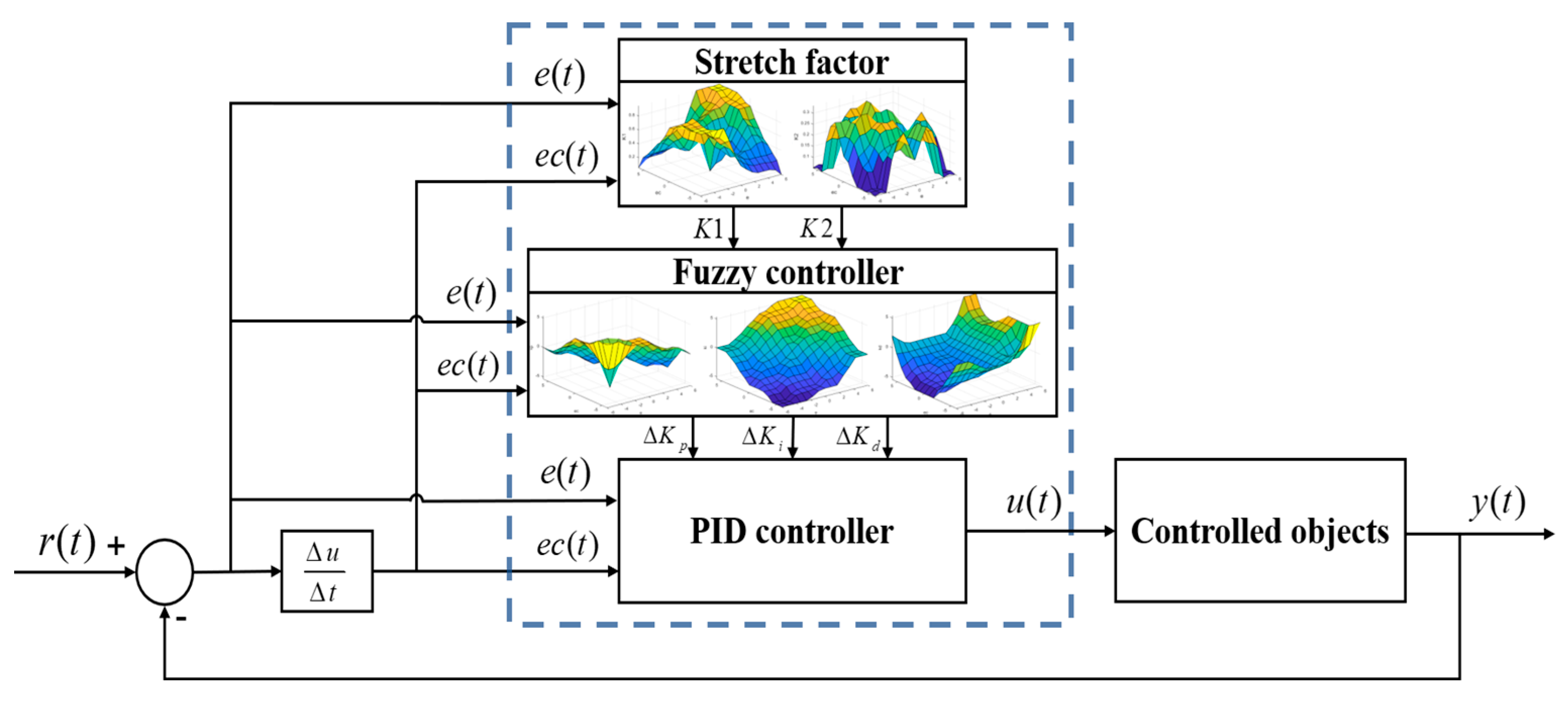
Usually, the braking process of EMB system is divided into brake clearance elimination stage, clamping force following stage and brake clearance formation stage according to the working state of the motor. In order to obtain higher control accuracy and improve the control quality of the EMB system, a clamping force control strategy based on VUF-PID controller is proposed for the clamping force following stage, which enables the EMB system to quickly reach the required target clamping force, control the motor to push the brake liner to clamp the brake disc, and the actual clamping force can be stably output according to the target clamping force.
The target response of the controlled system at time t is y ( t ) , the actual response is r ( t ) , and the difference between the two is the error e ( t ) , e ( t ) = y ( t ) r ( t ) . PID controller transfer function is obtained by linear combination of proportional, integral and differential errors.
u ( t ) = K p 0 e ( t ) + K i 0 0 t e ( t ) d t + K d 0 d e t d t
where K p 0 , K i 0 , K d 0 are the ratio, integral and differential coefficients respectively.
Fuzzy PID controller is an intelligent control strategy. Combining fuzzy control with PID control, the system can be adjusted in real time according to the current operating state of the system, with certain adaptive adjustment ability and good control effect [19]. The error e and error change rate e c of target clamping force and actual clamping force are selected as the input, PID parameter adjustment quantities Δ K p , Δ K i , Δ K d are selected as the output. Mamdani fuzzy reasoning method is adopted, and seven language variables are used to describe: negative big (NB), negative median (NM), negative small (NS), zero (ZE), positive small (PS), positive median (PM), and positive big (PB). Assuming that the domain of e , e c are [−24,000, 24,000] and [−2400, 2400], the domain of Δ K p , Δ K i , Δ K d are [−1, 1], [−0.1, 0.1] and [−0.002, 0.002]. The membership function selects trigonometric function.
The input and output variables are multiplied by the corresponding quantitative factors and the proportional factors, thus the transformation of the two-dimensional quantity from the basic field to the fuzzy field is realized, and the transformation of the precise quantity to the fuzzy quantity is realized. The quantitative factors of e , e c are K e , K e c , the proportion factors of the correction quantities Δ K p , Δ K i , Δ K d are K u p , K u i , K u d . After processing the fuzzy PID controller, the PID parameter adjustment quantities Δ K p , Δ K i , Δ K d are obtained. The fuzzy rules control table of PID parameters are shown in Table 1, Table 2 and Table 3 and the output adjustment quantities of the PID controller is determined by Equation (11).
K p = K p 0 + Δ K p K u p K i = K i 0 + Δ K i K u i K d = K d 0 + Δ K d K u d
where K p 0 , K i 0 , K d 0 are the initial parameters of the PID controller.
The center of gravity method is used to de-fuzzy, and the calculation formula is expressed:
u k = k = 1 m y k A y k k = 1 m A y k
where u k is the output control quantity of the controller; y k is the center of the fuzzy set generated for the rule; A ( y k ) is the area under the membership function corresponding to the rule; m is the number of output variables.
Fuzzy PID controller has the ability of adaptive adjustment, but the ability of adaptive adjustment is uncertain. Although the fuzzy PID controller can make the system have a certain stability through real-time adaptive adjustment, the rough and redundant rules of the controller design will prolong the adjustment time of the system. Therefore, this paper adds a scaling factor on the basis of fuzzy PID control to adjust the system online in real time, so that the system can obtain appropriate parameter values to improve the adaptive ability of the system and enhance the fault tolerance of the system.
From Equation (10), the values of K p , K i , K d affect the output of the controller, but the values of K p , K i that have a greater impact on the control effect. Therefore, when designing the variable domain adaptive control algorithm in this paper, it mainly carries out variable domain analysis on the values of K p , K i . According to the analysis of two-dimensional input and output variables of fuzzy PID controller, the membership function of input variables can be regarded as the constraint input domains, which can weaken the quantization factors. Therefore, the scale factor and integral factor that have significant influence are selected to adjust adaptively on the system. The structure block diagram of VUF-PID controller is shown in Figure 3, where K1 and K2 are the scaling factors of the domain.
The commonly used methods to design scaling factors are mainly based on adaptive function and fuzzy language. The method based on adaptive function has simple structure and control of the scaling factor of the domain, which is difficult to be applied to complex practical engineering applications. Therefore, this paper chooses the method based on fuzzy language to scale the domain.
The input variables are e , e c 
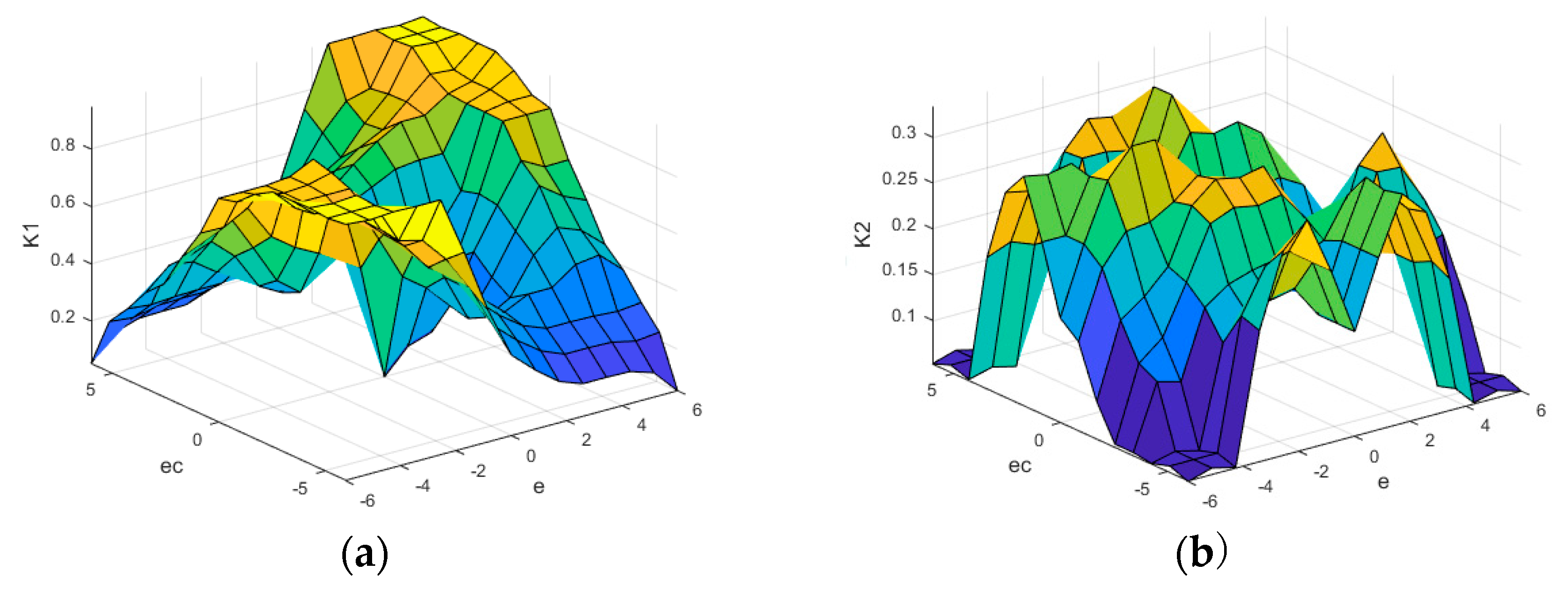
, the same as the basic fuzzy controller, the fuzzy set theory domains are both [−6, 6], and the fuzzy language variables are both represented by {BN, MN, SN, ZE, SP, MP, BP}. The output variables are the scale factors K 1 and K 2 , and the fuzzy set theory domains are both [0, 1]. The fuzzy language variables are represented by {zero, small, small, small, large, large, maximum}, namely {ZE, VS, LS, S, LB, B, VB}, and the membership functions select trigonal function. The input-output relation surface of VUF-PID controller is shown in Figure 4.

4. Simulation Results and Discussion

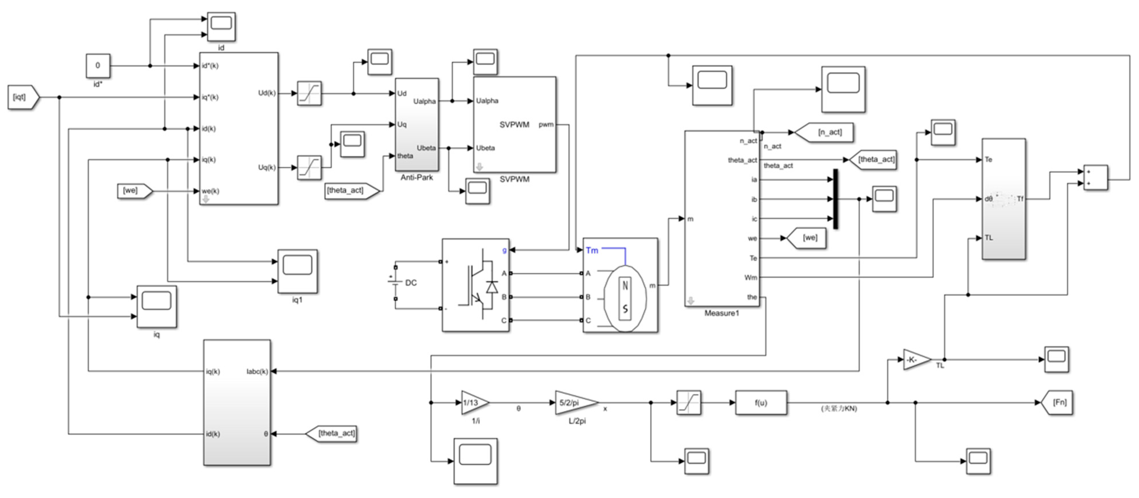
The mathematical model of EMB system is established in MATLAB/Simulink software in this paper, as shown in Figure 5. The parameters of the VUF-PID controller and simulation model are shown in Table 4 and Table 5 respectively. In order to verify the advantages of the VUF-PID control strategy designed for clamping force control, the differences between VUF-PID and PID and fuzzy PID (F-PID) control are analyzed by simulation comparison. The comparison simulation results are shown in Figure 6, Figure 7 and Figure 8. The simulation analysis of step braking condition, brake gear switching condition and sine braking condition is carried out.
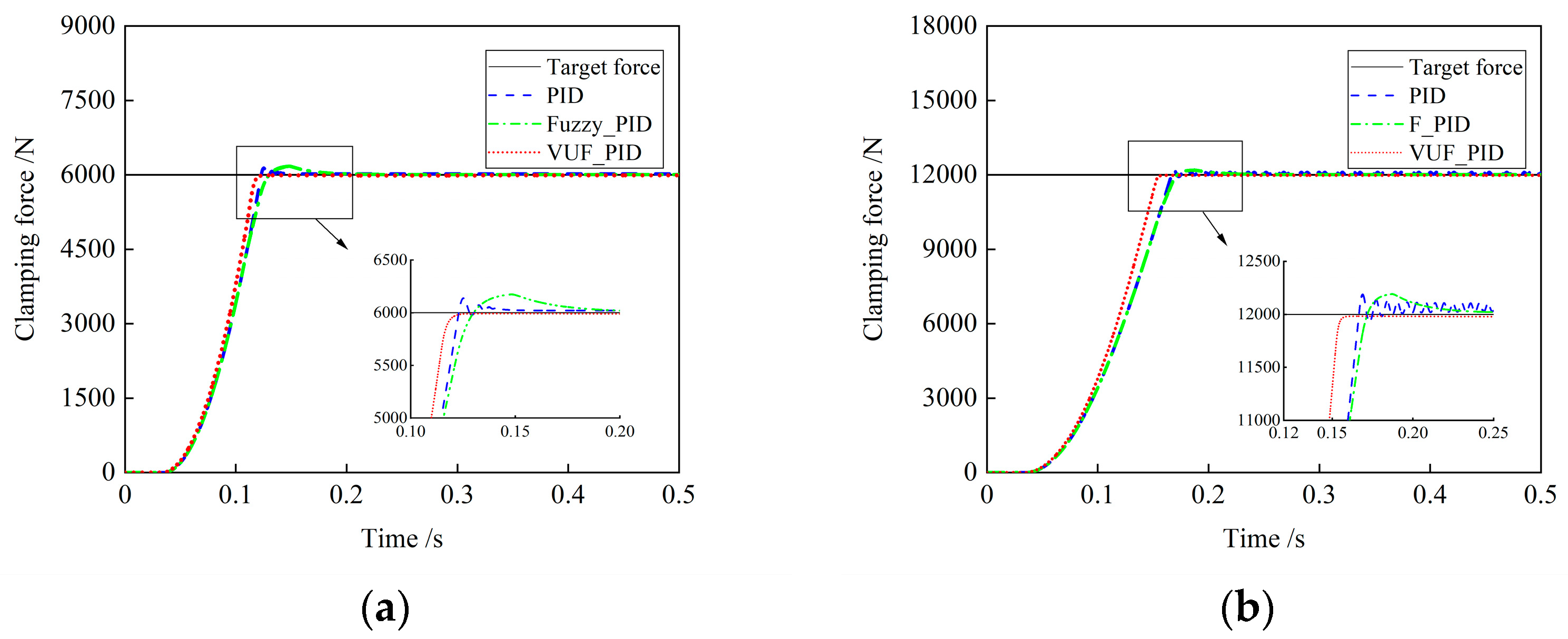
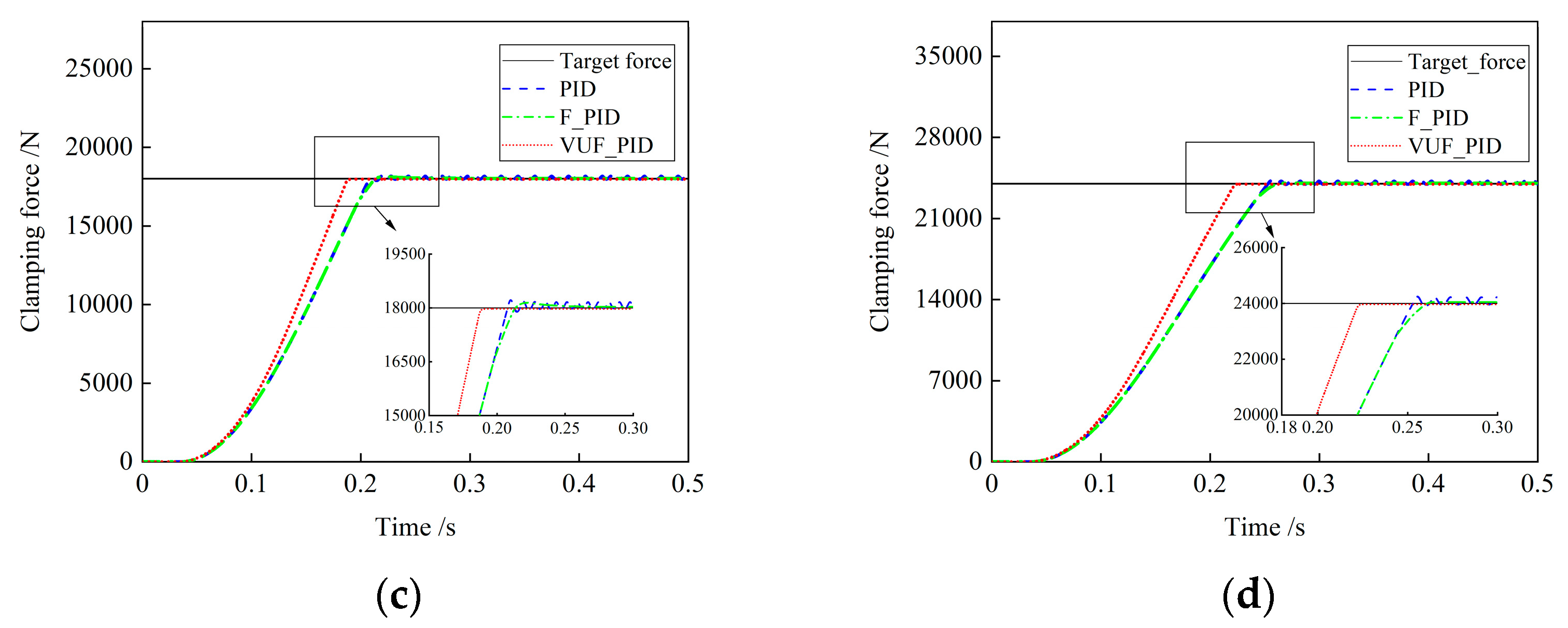
(1) Simulation analysis of step braking condition
Step signals of 6000 N, 12,000 N, 18,000 N and 24,000 N are respectively applied to the input end of the target clamping force of the EMB system actuator. The simulation curves of clamping force response characteristics in the control system are shown in Figure 6. By comparison with Figure 6, simulation effect parameters of the three EMB control strategies are shown in Table 6.
By comparing the simulation parameters of the three EMB control strategies shown in Table 6, it can be seen that the maximum adjustment time of PID control is 0.274 s and the maximum overshoot is 2.28%. The maximum adjustment time of F-PID control is 0.272 s and the maximum overshoot is 2.85%. The maximum adjustment time is 0.209 s and the maximum overshoot is 0.17%. Before the target clamping force is 12,000 N, the effect of PID control is better than that of F-PID control. However, with the increasing clamping force, F-PID control will gradually be stronger than PID control. In addition, when PID control controls the clamping force with large amplitude, there will be oscillation and large steady-state error. The VUF-PID controller designed in this paper has good tracking performance for different target clamping forces. The adjustment time and overshoot of EMB system are effectively reduced, and the dynamic and steady state performance are significantly improved.
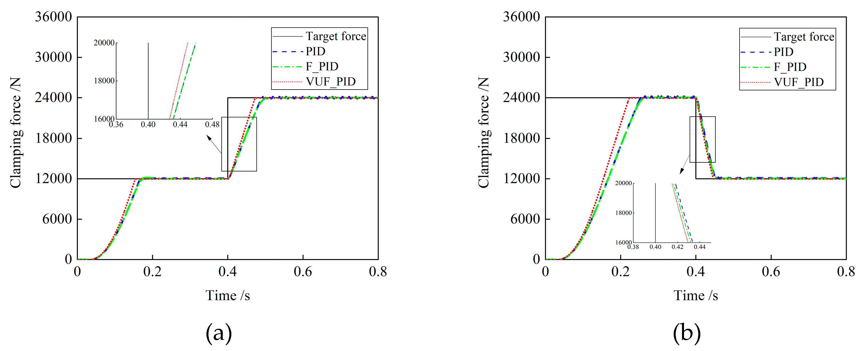
(2) Simulation analysis of brake gear switching condition
When the car is braking, it also needs to switch the brake gear. At this time, the EMB system needs to quickly follow the target clamping force expected by the driver of different gear within a certain period of time. The dynamic simulation conditions are as follows: (a) Brake gear increasing switching conditions, applying brake gear 0–12,000–24,000 N. (b) Brake gear decreasing switching condition, applying brake gear 24,000–12,000–0 N. Figure 7 shows the simulation curves of clamping force response under increasing brake gear switching condition and decreasing brake gear switching condition.
Figure 7a shows the clamping force response characteristic curve of EMB system under increasing brake gear switching condition. In the process of actual clamping force jumping from 12,000 N to 24,000 N, the clamping force response time with VUF-PID, F-PID, and PID control are 0.0755 s, 0.1083 s, and 0.1291 s. The control effect of VUF-PID is 30.28% and 41.52% faster than the other two kinds, respectively. Figure 7b shows the clamping force response characteristic curve of EMB system under increasing brake gear switching condition. In the process of actual clamping force jumping from 24,000 N to 12,000 N, the clamping force response time with VUF-PID, F-PID, and PID control are 0.0471 s, 0.0512 s, and 0.0603 s. The control effect of VUF-PID is 8.01% and 21.89% faster than the other two kinds respectively. It can be seen that the VUF-PID control proposed in this paper still has a good adaptive adjustment ability under the braking gear switching conditions, especially in the initial stage of response, the gain parameters can be better adjusted according to the error and error change rate, so that the desired clamping force can be reached stably, quickly and accurately.
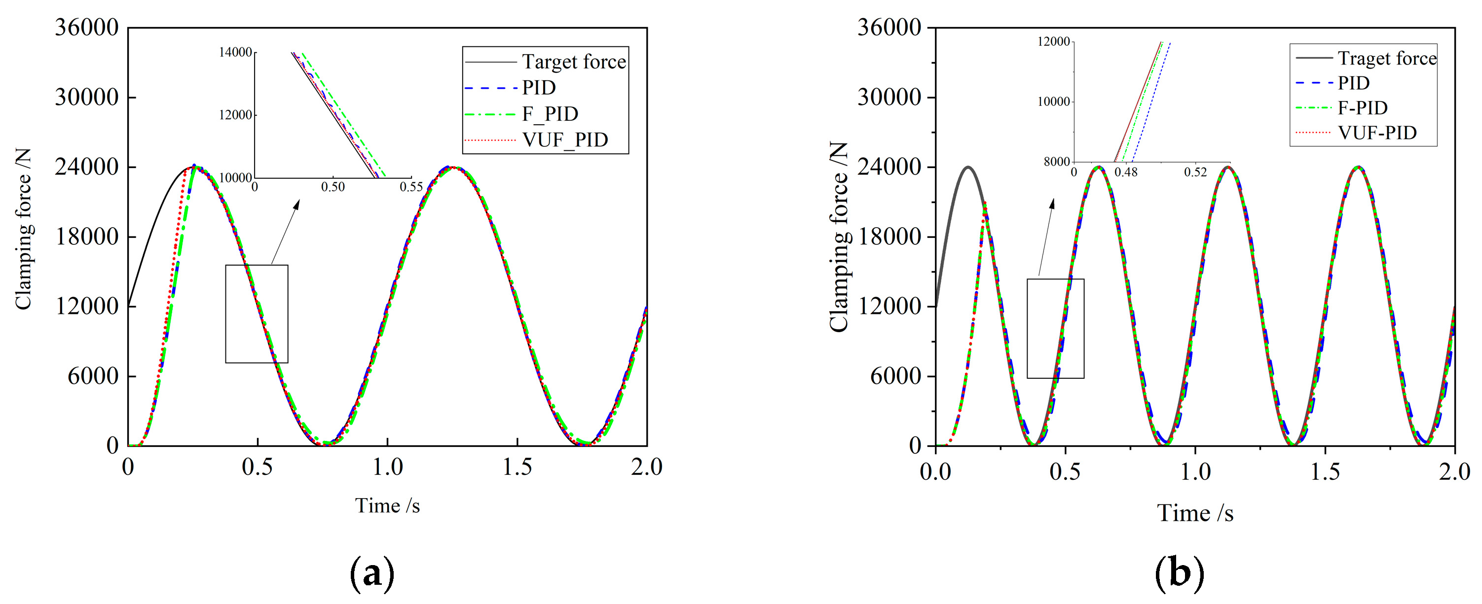
(3) Sinusoidal working condition simulation analysis
Sinusoidal signal with amplitude 24,000 N and a frequency of 1 Hz and 2 Hz applied to the target clamping force input of the EMB system actuator. The simulation curve of clamping force response characteristics in the control system is shown in Figure 8.
Figure 8 shows the clamping force response characteristic curve of EMB system under sinusoidal condition. PID control has better clamping force control effect in sinusoidal condition than F-PID control, because the target clamping force value in sinusoidal condition is changing all the time, the adaptive adjustment capability of F-PID control requires a certain adjustment time, so there is a certain delay in following the target clamping force in the heel sine condition, and there will be an error when following the clamping force value of the target at the next moment. However, PID control has certain jitter when following the clamping force of time-varying target, because PID control lacks the ability of adaptive adjustment in the face of changing errors. The proposed VUF-PID control introduces stretching factors into the design, which improves the following ability to cope with the moment change of the target clamping force condition, can adjust the proportional factor and integral factor in time, shorten the adaptive adjustment time, and quickly reach the target clamping force value at the moment, indicating that VUF-PIF control has stronger tracking performance and robustness performance.

5. Conclusions

The quality of clamping force control is an important factor affecting the braking performance of EMB system, which is also the focus and difficulty of current research on EMB system. In order to improve the clamping force control performance of EMB system, an EMB clamping force control method based on VUF-PID controller is proposed, and stretching factors are added to improve the fuzzy PID control. According to the running state of the controlled object, the fuzzy domain can be adjusted in real time to keep the system in the proper parameter value and improve the adaptive ability of the system. Finally, the response characteristics and effectiveness of clamping force under step braking condition, gear switching braking condition and sinusoidal braking condition are verified by simulation experiments. The simulation results show that, compared with PID control and F-PID control, VUF-PID control has the advantages of short response time, good following effect and strong adaptability for different clamping force target values, which can meet the braking requirements under different braking conditions.

Author Contributions

Conceptualization, methodology, Q.C. and Z.L.; writing—original draft preparation, Q.C. and Z.L.; writing—review and editing, Z.L. and H.T.; investigation, Z.X. All authors have read and agreed to the published version of the manuscript.

Funding

This research was supported by the National Natural Science Foundation of China (Grant No. 52162044), and the Key Research and Development Program of Jiangxi Province (Grant No. 20212BBE51014 and 20224BBE52003).

Data Availability Statement

Data sharing is not applicable.

Acknowledgments

The authors would like to thank anonymous reviewers for their helpful comments and suggestions to improve the manuscript.

Conflicts of Interest

The authors declare no conflict of interest.

References

  1. Emadi, A.; Lee, Y.J.; Rajashekara, K. Power Electronics and Motor Drives in Electric, Hybrid Electric, and Plug-In Hybrid Electric Vehicles. IEEE Trans. Ind. Electron. 2008, 55, 2237–2245. [Google Scholar] [CrossRef]
  2. Schrade, S.; Nowak, X.; Verhagen, A.; Schramm, D. Short Review of EMB Systems Related to Safety Concepts. Actuators 2022, 11, 214. [Google Scholar] [CrossRef]
  3. Saric, S.; Bab-Hadiashar, A.; van der Walt, J. Estimating clamp force for brake-by-wire systems: Thermal considerations. Mechatronics 2009, 19, 886–895. [Google Scholar] [CrossRef]
  4. Ki, Y.H.; Lee, K.J.; Cheon, J.S.; Ahn, H.S. Design and implementation of a new clamping force estimator in Electro-Mechanical Brake systems. Int. J. Automot. Technol. 2013, 14, 739–745. [Google Scholar] [CrossRef]
  5. Gong, X.; Ge, W.; Yan, J.; Zhang, Y.; Gongye, X. Review on the Development, Control Method and Application Prospect of Brake-by-Wire Actuator. Actuators 2020, 9, 15. [Google Scholar] [CrossRef] [Green Version]
  6. Krishnamurthy, P.; Lu, W.; Khorrami, F.; Keyhani, A. Robust Force Control of an SRM-Based Electromechanical Brake and Experimental Results. IEEE Trans. Control Syst. Technol. 2009, 17, 1306–1317. [Google Scholar] [CrossRef]
  7. Han, K.; Kim, M.; Huh, K. Modeling and control of an electronic wedge brake. Proc. Inst. Mech. Eng. Part C J. Mech. Eng. Sci. 2012, 226, 2440–2455. [Google Scholar] [CrossRef]
  8. Baek, S.-K.; Oh, H.-K.; Park, J.-H.; Shin, Y.-J.; Kim, S.-W. Evaluation of Efficient Operation for Electromechanical Brake Using Maximum Torque per Ampere Control. Energies 2019, 12, 1869. [Google Scholar] [CrossRef] [Green Version]
  9. Park, G.; Choi, S.B. Clamping force control based on dynamic model estimation for electromechanical brakes. Proc. Inst. Mech. Eng. Part D J. Automob. Eng. 2018, 232, 2000–2013. [Google Scholar] [CrossRef]
  10. Lee, Y.O.; Jang, M.; Lee, W. Novel clamping force control for electric parking brake systems. Mechatronics 2011, 21, 1156–1162. [Google Scholar] [CrossRef]
  11. Line, C.; Manzie, C.; Good, M.C. Electromechanical Brake Modeling and Control: From PI to MPC. IEEE Trans. Control Syst. Technol. 2008, 16, 446–457. [Google Scholar] [CrossRef]
  12. Zhao, Y.; Lin, H.; Elahi, H.; Miao, F.; Riaz, S. Clamping Force Sensor Fault Analysis and Fault-Tolerant Control of the Electromechanical Brake System. Arab. J. Sci. Eng. 2023, 48, 6011–6023. [Google Scholar] [CrossRef]
  13. Jo, C.; Hwang, S.; Kim, H. Clamping-Force Control for Electromechanical Brake. IEEE Trans. Veh. Technol. 2010, 59, 3205–3212. [Google Scholar] [CrossRef]
  14. Park, G.; Choi, S.; Hyun, D. Clamping force estimation based on hysteresis modeling for electro-mechanical brakes. Int. J. Automot. Technol. 2017, 18, 883–890. [Google Scholar] [CrossRef]
  15. Lee, C.F.; Manzie, C. Near-time-optimal tracking controller design for an automotive electromechanical brake. Proc. Inst. Mech. Eng. Part I J. Syst. Control Eng. 2012, 226, 537–549. [Google Scholar] [CrossRef]
  16. Li, Y.; Shim, T.; Shin, D.-H.; Lee, S.; Jin, S. Control System Design for Electromechanical Brake System Using Novel Clamping Force Model and Estimator. IEEE Trans. Veh. Technol. 2021, 70, 8653–8668. [Google Scholar] [CrossRef]
  17. Hoseinnezhad, R.; Bab-Hadiashar, A.; Rocco, T. Real-Time Clamp Force Measurement in Electromechanical Brake Calipers. IEEE Trans. Veh. Technol. 2008, 57, 770–777. [Google Scholar] [CrossRef]
  18. Liu, Z.; Chen, Y.; Chen, L. A Gap Control Method for Electromechanical Brakes. Acta Armamentarii 2022, 43, 1478–1487. [Google Scholar]
  19. Conker, C.; Baltacioglu, M.K. Fuzzy self-adaptive PID control technique for driving HHO dry cell systems. Int. J. Hydrogen Energy 2020, 45, 26059–26069. [Google Scholar] [CrossRef]
Figure 1. Schematic diagram of the EMB brake system.
Actuators 12 00272 g001
Figure 2. Static frictional characteristic curve of the motor.
Actuators 12 00272 g002
Figure 3. The structure block diagram of VUF-PID controller.
Actuators 12 00272 g003
Figure 4. VUF-PID controller input-output relationship surface: (a) the scale factors K1; (b) the scale factors K2.
Actuators 12 00272 g004
Figure 5. The mathematical model of EMB system.
Actuators 12 00272 g005
Figure 6. Clamping force response curve under step braking condition: The target clamping force is (a) 6000N; (b) 12,000 N; (c) 18,000 N; (d) 24,000 N.
Actuators 12 00272 g006aActuators 12 00272 g006b
Figure 7. Clamping force response curve under brake gear switching condition: The target clamping force is (a) 0–12,000–24,000 N; (b) 24,000–12,000–0 N.
Actuators 12 00272 g007
Figure 8. Clamping force response curve under Sinusoidal working condition. (a) 1 Hz; (b) 2 Hz.
Actuators 12 00272 g008
Table 1. The fuzzy rules control table of Δ K p .
eec
NBNMNSZEPSPMPB
NBNBNBNMNMNSZEZE
NMNBNBNMNSNSZEZE
NSNBNMNSNSZEPSPS
ZENMNMNSZEPSPMPM
PSNMNSZEPSPSPMPB
PMZEZEPSPSPMPBPB
PBZEZEPSPMPMPBPB
Table 2. The fuzzy rules control table of Δ K i .
eec
NBNMNSZEPSPMPB
NBPBPBPMPMPSZEZE
NMPBPBPMPSPSZENS
NSPMPMPMPSZENSNS
ZEPMPMPSZENSNMNM
PSPSPSZENSNSNMNM
PMPSZENSNMNMNMNB
PBZEZENMNMNMNBNB
Table 3. The fuzzy rules control table of Δ K d .
eec
NBNMNSZEPSPMPB
NBPSNSNBNBNBNMPS
NMPSNSNBNMNMNSZE
NSZENSNMNMNSNSZE
ZEZENSNSNSNSNSZE
PSZEZEZEZEZEZEZE
PMPBNSPSPSPSPSPB
PBPBPMPMPMPSPSPB
Table 4. The fuzzy rules control table of Δ K d .
ParameterSymbolValueParameterSymbolValue
Initial parameters of the scale factor K p 0 10Quantification factor of Δ e K e c 0.0025
Initial parameters of the integral factor K i 0 0.02Scale factor of Δ K p K u p 0.17
Initial parameters of the differential factor K d 0 0.002Scale factor of Δ K i K u i 0.017
Quantification factor of e K e 0.00025Scale factor of Δ K d K u d 0.00033
Table 5. The fuzzy rules control table of Δ K d .
ParameterSymbolValue
Static friction torque (N·m) T s 0.0387
Coulomb friction torque (N·m) T c 0.0192
Coefficient of viscous friction (N m (rad/s)−1) B 1.086 × 10⁻³
Ball screw drive efficiency η s 0.92
Planetary gearing efficiency η p 0.97
Ball Screw Guide (mm) L 5
Planetary gear ratio i p 13
Table 6. Comparison of simulation results of three EMB control strategies.
Target
Clamping Force (N)
PIDF-PIDVUF-PID
Adjustment TimeOvershootAdjustment TimeOvershootAdjustment TimeOvershoot
60000.154 s2.28%0.191 s2.85%0.128 s0.17%
12,0000.199 s1.57%0.229 s1.58%0.162 s0.16%
18,0000.238 s1.33%0.246 s1.31%0.176 s0.16%
24,0000.274 s1.06%0.272 s0.37%0.209 s0.15%
Disclaimer/Publisher’s Note: The statements, opinions and data contained in all publications are solely those of the individual author(s) and contributor(s) and not of MDPI and/or the editor(s). MDPI and/or the editor(s) disclaim responsibility for any injury to people or property resulting from any ideas, methods, instructions or products referred to in the content.

