Article

Modeling and Experimental Validation of the Performance of Electromechanical Height Adjustment Vehicle Suspension with Eccentric Mounted Screw System

1
Department of Mechanical and Aerospace Engineering, Politecnico di Torino, 10129 Turin, Italy
2
Department of Mechanical and Aerospace Engineering, Turin Polytechnic University in Tashkent, Tashkent 100095, Uzbekistan
3
Department of Traffic Engineering and Management, Kimyo International University in Tashkent, Tashkent 100121, Uzbekistan
4
School of Engineering and Sciences, Tecnologico de Monterrey, Mexico City 14380, Mexico
*
Author to whom correspondence should be addressed.
Actuators 2023, 12(7), 264; https://doi.org/10.3390/act12070264
Submission received: 3 June 2023 / Revised: 25 June 2023 / Accepted: 26 June 2023 / Published: 28 June 2023
(This article belongs to the Special Issue Actuators and Control of Intelligent Electric Vehicles)

Abstract

:
This paper describes the modeling and experimental validation of the performance of two height adjustment suspensions with concentrically and eccentrically mounted screws. In the former solution, an anti-rotation system is required for the generation of reaction torque on the power screw–nut mechanism. The anti-rotation represents the main drawback of such mechanisms. In contrast, the eccentric solution attempts to solve this problem by placing the screw–nut mechanism eccentrically with respect to the shock absorber tube axis. In this paper, the working principle of the eccentric solution is explained. Its performance is compared to the concentric counterpart through simulations and experiments. Although the efficiencies of eccentric and concentric systems are very similar at the power screw, overall efficiencies differ substantially. During lifting, average efficiencies are around 3.4% and 6.5% for concentric and eccentric systems, respectively. When lowering, these values are 6.2% and 26%. The higher overall efficiency of the eccentric screw system is attributed to the anti-rotation system and the balancing of the bending moment due to the offset application of the load. To yield a complete perspective on the eccentric mounted screw solution, four prototypes are installed and tested on a demo vehicle.

1. Introduction

The current trend in the automotive sector, as one of the main contributors of carbon dioxide ( CO 2 ) emissions worldwide [1], is to widen the usage of low carbon emission technologies to reduce air pollution. To comply with more stringent legislative vehicle emission regulations, vehicle manufacturers are using different novel solutions applied to all vehicle systems and components [2,3,4,5]. Currently, the upper limit for corporate emission levels is 95 gCO 2 / km [6,7]. Considering that the corporate average emission level of most vehicle manufacturers is around 120 gCO 2 / km , researchers and engineers must deal with technologies that push emissions to lower limits. In this regard, height adjustable suspensions offer notable benefits with regard to fuel consumption and emission reduction and improved comfort for a reasonable cost [8,9,10,11].
One of the earliest studies on the influence of ground effect on vehicle aerodynamics was published by Cogotti [12]. Later, Schuetz [13] demonstrated that reducing the ground clearance leads to a decrease in aerodynamic drag; however, he stated that the reason behind this reduction is obscure.
Amati et al. [11] have performed a detailed analysis of height adjustment suspensions. They developed two electromechanical height adjustment prototypes and demonstrated that the vehicle fuel consumption for an average class A vehicle can be reduced consequently as a result of aerodynamic drag force reduction. The improvement figures range from 0.88% to 4.41% when the vehicle height is reduced by 20 to 40 mm , respectively. This leads to a corresponding reduction in CO 2 emissions of 0.87 to 5.17 g / km . The main contributors to the vehicle’s aerodynamic drag force are its drag coefficient and frontal area [11]. Although the reason for the reduction in vehicle drag coefficient at lower ground clearance is not clear [13,14], to a certain extent, it can be attributed to underbody behavior [14,15]. Further benefits of height adjustment systems are improved passenger comfort when entering and exiting the vehicle, the possibility of the pitch reduction when the vehicle load distribution changes [9,10], and an increased downforce with reduced ground clearance [15].
Among possible actuation solutions, electromechanical ones are particularly favored due to their oil-free feature. Recent efforts in the automotive field have pushed this transition, with mechatronic solutions used in clutches [16,17], gearboxes [18] and differential mechanisms [19]. In this regard, power screw-based electromechanical height adjustment systems are intrinsically irreversible. Thereby, they present a favorable degree of fault tolerance and reliability. Additionally, they are compact and relatively affordable. When dealing with any kind of actuator, the layout of components is crucial in yielding a power-efficient solution. In the case of power screw-based systems, the first intuitive idea of placing the screw concentric to the shock absorber tube may arise. In previous work [11], a concentric screw prototype commonly available in the state of the art [20] was tested. Its layout was similar to the one depicted in Figure 1a. Results evidenced that the system performance was limited, due to the large diameter of the power screw constrained by the shock absorber tube bulk and the presence of an anti-rotation system. The former problem has been resolved in a patented solution [21], where the lower spring holder is actuated by means of a leverage mechanism. Thus, the system is more compact and the screw can have a smaller diameter. Moreover, the presence of a leverage mechanism provides further amplification of the lifting force. However, the anti-rotation system is still needed and the additional spring increases the system cost.
This background highlights the main drawbacks of concentric solutions. To address these shortcomings, an evolved height-adjustable suspension system is proposed. It is characterized by an eccentrically mounted screw, as shown in Figure 1b. The solution was developed, validated and patented by the authors [22]. Although the patent contains a detailed description of the invention, the working principle and the performance validation are not available in the literature. Moreover, this novel eccentric concept is not treated in other works from the technical and scientific community.
The contributions of this paper are (i) to provide a numerical model of an eccentric screw solution for height adjustment suspensions; (ii) to determine experimentally the performance of an eccentric screw prototype; and (iii) to compare concentric and eccentric system performances in terms of actuation speed, power request, and overall efficiency, to determine the most advantageous solution.
The manuscript is organized as follows. Section 2 contains a general description of the analyzed systems, with particular emphasis on the novel eccentric solution. Subsequently, Section 3 provides the foundations for numerical modeling. In Section 4, experiments performed on a dedicated testbed are analyzed; both solutions are compared in terms of performance and efficiency metrics. Section 5 presents the testing of four eccentric screw prototypes on a demo vehicle. Finally, Section 6 concludes the work.

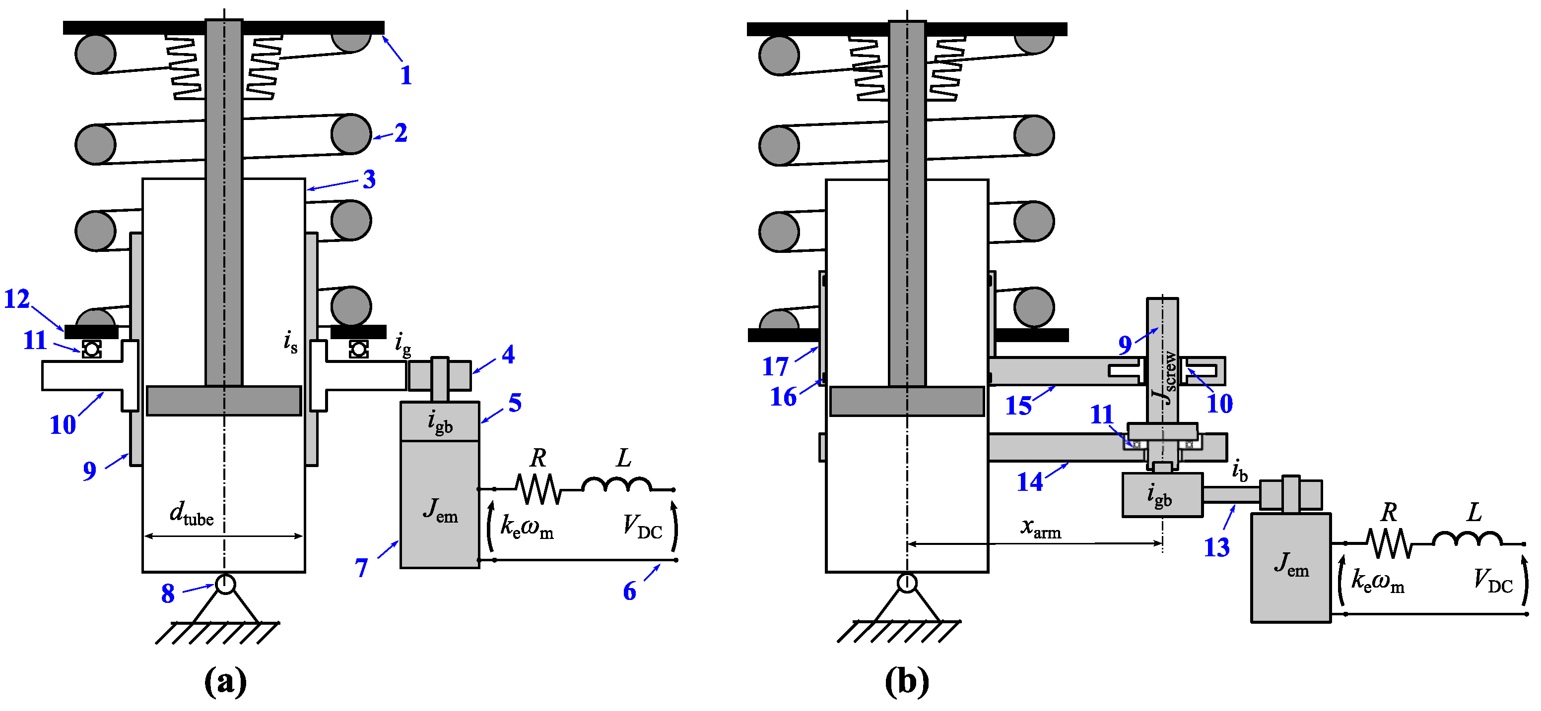
2. Description of the System

2.1. Working Principle

Figure 1b shows a schematic of a novel power screw actuation layout where the screw is mounted eccentrically with respect to the shock absorber tube [22]. This eccentricity leads to two main advantages: intrinsic anti-rotation and a screw with a smaller diameter. As shown in the scheme, the nut is fixed to the upper lever and translates together with the latter during actuation. The guiding element avoids nut tilting and, hence, screw bending due to eccentric load by balancing the rotational moment on two sliding bushings located at the guide extremities.
The working principle of the height adjustment system with concentric screw is described in detail in Amati et al. [11]. The working principle of the eccentric solution is described here with reference to Figure 1b. An electric motor 7 rotates the power screw 9 through the gearbox 5. The power screw sits on the lower arm 14 on an axial thrust bearing 11; hence, the screw is decoupled from the lower arm. The casing of electric motor 7 is fixed on lower arm 14; therefore, it does not translate. Power is supplied by an onboard electric battery 6. Depending on the available envelope, the gearbox can present different architectures. For example, a two- or three-stage planetary drive [23] is possible. Alternatively, a more compact single- [24] or dual-stage cycloid drive [25], belt drive, or a combination of the aforementioned solutions can be used [26,27]. The rotational motion of the screw is then transformed into linear translation by means of a nut 10 fixed to an upper arm 15. This upper arm 15 transmits motion from an eccentrically mounted screw to a guiding element 17, which tightly slides on a rectified shock absorber tube 3. A lower spring holder 12 is fixed on the upper end of the guiding element. Hence, actuation is performed on the lower spring holder level. The bending moment due to the eccentric actuation is balanced at the extremities of the guiding element by means of two bushings 16. The anti-rotation action is accomplished on the eccentrically mounted screw body. Therefore, the screw must also be designed to withstand the anti-rotation bending torque.

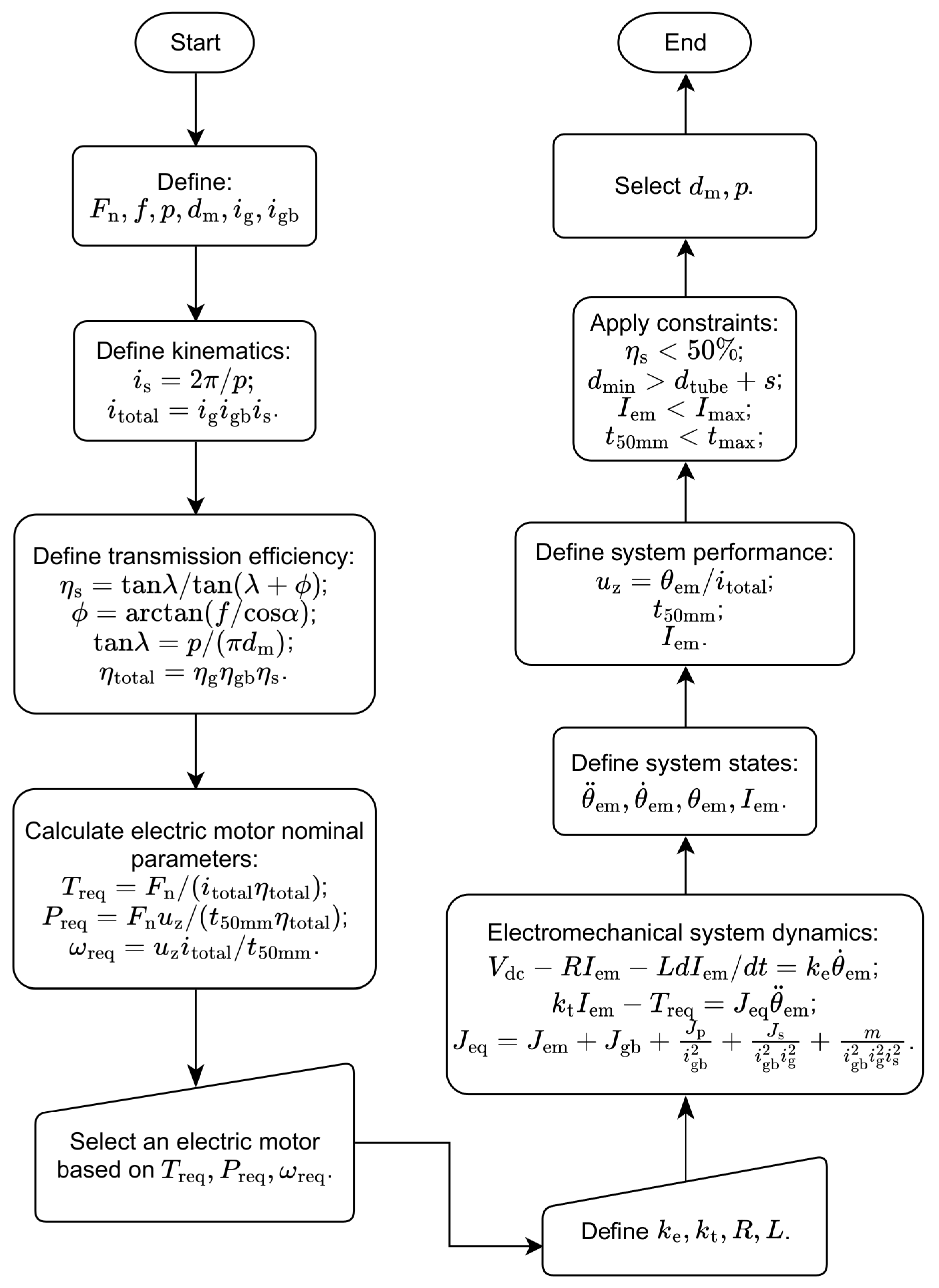
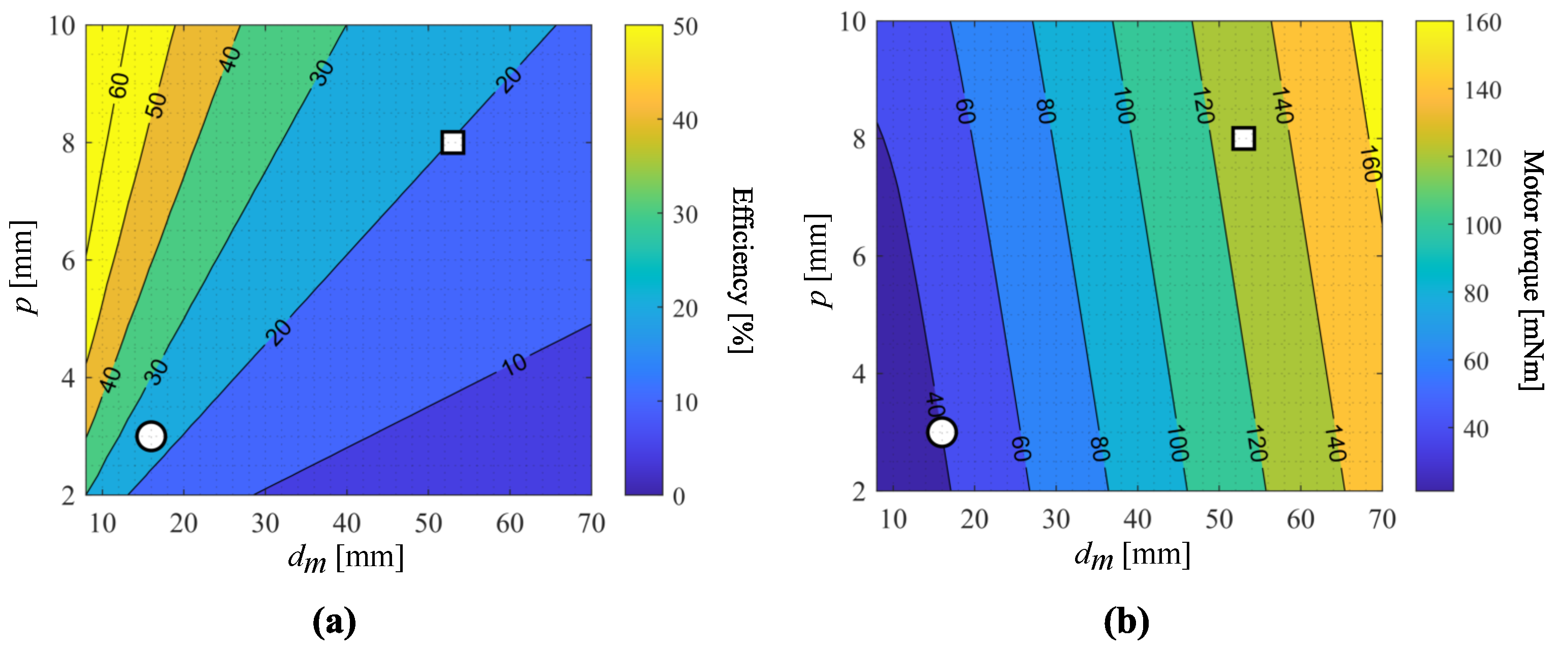
2.2. Component Sizing

This subsection describes briefly the design of the main components of the electromechanical actuation system. For a detailed description of the methodology and corresponding equations, the reader can refer to the work by Amati et al. [11]. A suitable electric motor can be selected based on the required power to lift the load and by applying the constraints listed in Table 1. Then, the geometrical and mechanical parameters of the power screw mechanism can be defined. Figure 2 depicts the flowchart of the calculation procedure used for the selection of the electric motor and the definition of the power screw main parameters.
The design methodology started by defining the load F n , the friction coefficient f s between screw and nut, mean diameter d and pitch p of the power screw, and transmission ratios of single-stage gearbox i g and planetary gear i gb . Then, the transmission ratio of the screw i s and total transmission ratio i tot were defined. The screw efficiency η s is defined as a function of the lead angle λ , friction angle ϕ , thread angle α , and thread friction coefficient f s . The total transmission efficiency η tot is the product of efficiencies of the screw η s , single-stage gear η g , and planetary gear η gb . The nominal parameters of the electric motor (torque T req , angular speed ω req , and power P req ) to drive the load F n were calculated. A commercial motor with the closest nominal parameters was then selected. Such electrical parameters of the motor, such as torque constant k t , speed constant k e , phase-to-phase resistance, and inductance, were specified from available data. Combined electrical and mechanical dynamics of the actuation system were used to define the system states, such as motor angular acceleration θ ¨ em , speed ω em = θ ˙ em , and displacement θ em , as well as actuation current I em . The electrical circuit model considers the voltage balance of external power supply V dc , voltage drop due to resistance and inductance, and motor back electromotive force (EMF). The mechanical dynamics of the motor include driving the equivalent inertia J eq and the requested torque. The performance of the system was determined in terms of the time t 50 to fulfill a stroke displacement u z = 50 mm and steady-state current absorption I ss .
An irreversible screw, i.e., with an efficiency lower than 50%, was selected while satisfying the constraints indicated in Table 1. For an actuator with a concentrically mounted screw, a constraint must be applied to the minor diameter of the screw d min :
d min > d tube + s
where d tube is the shock absorber tube diameter and s is an additional thickness. This constraint is not needed for the solution with an eccentrically mounted screw because the screw and the shock absorber tube are independent. Finally, the appropriate screw diameter d m and pitch p were selected.
Final design points for concentrically and eccentrically mounted screw solutions are indicated in Figure 3a,b, with square and circular markers, respectively. Results show that the screw efficiency η s is higher for smaller screw diameters d m and larger screw pitches p. Correspondingly, the electric motor torque is also smaller when a reduced screw diameter is used. The screw’s mechanical strength and fatigue life calculations were also verified in the sizing procedure. However, these analyses are not described here, as they are beyond the scope of this work.

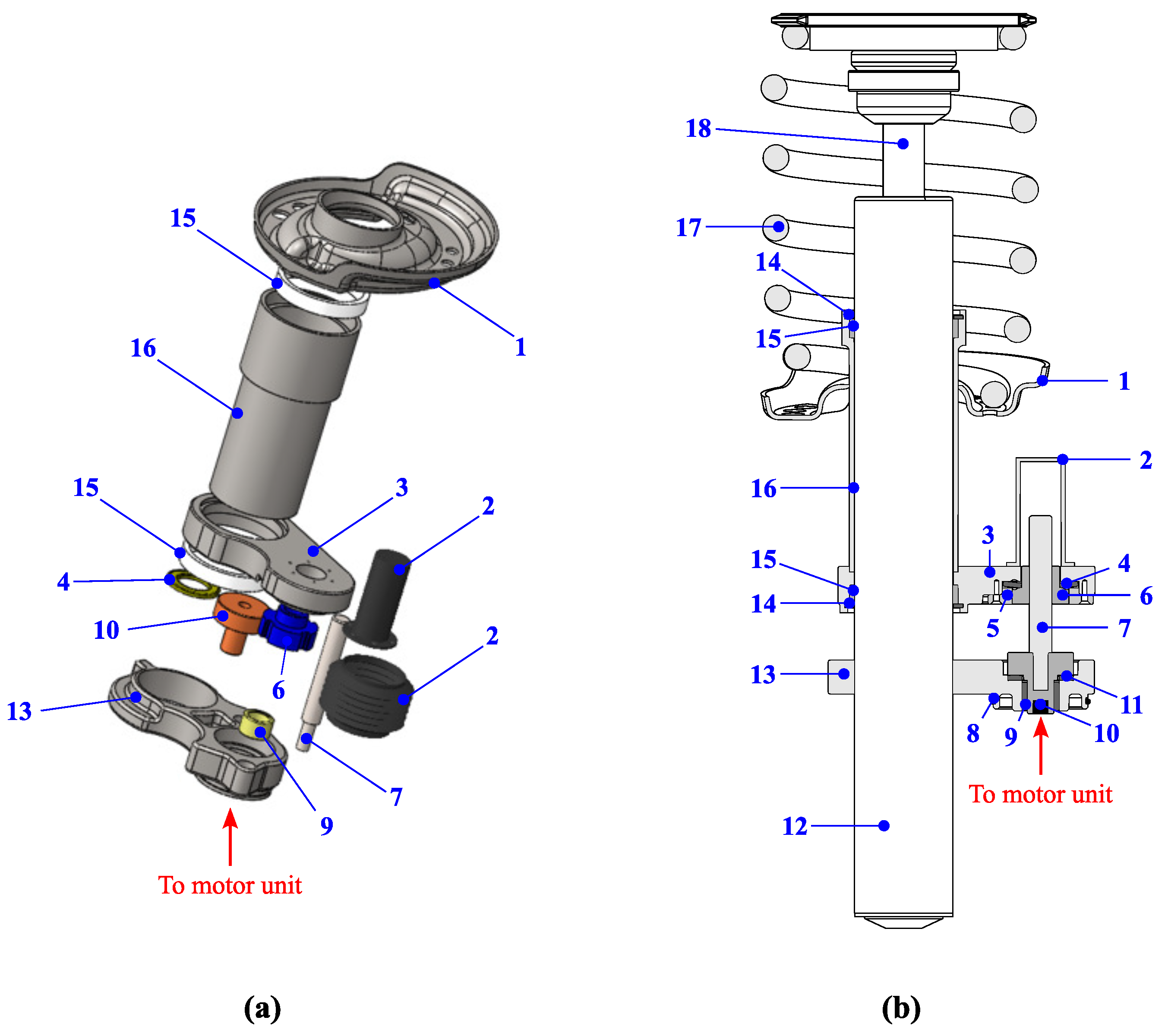
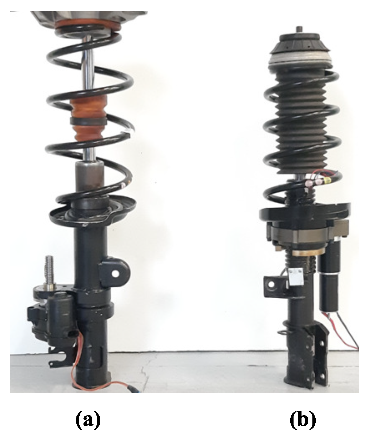
2.3. Eccentric Screw Actuator Prototype

A height adjustment system with a trapezoidal screw was developed based on the above-mentioned considerations. A 3D drawing and cross-section are illustrated in Figure 4. The trapezoidal threaded power screw 7 (Tr 16x3) is shrink-fitted to screw adapter 11, which has a spline interface with the gearbox output shaft. The screw seats on the lower arm 13 (welded on the shock absorber tube 12) on the axial thrust bearing 11 to decouple rotating and fixed parts. An off-the-shelf motor unit [26] is used to drive the power screw (not shown in Figure 4a). It consists of a brushed direct-current (DC) electric motor, a toothed belt transmission, and a two-stage planetary gearbox. The toothed belt transmits the torque from the electric motor shaft to the input sun gear of the planetary gearbox located at a given distance. It works as a parallel-axes speed reducer with a ratio of 3. The planetary gearbox is composed of two stages and an overall speed reduction ratio of 50. The nut 6 is mounted on the upper arm 3 by means of the elastic member 4 and the nut interface 5. The elastic member 4 is used to compensate for small misalignments of the upper arm 3. The latter is welded to the guiding element 16, on which the lower spring holder 1 is also welded. The guiding element slides on the rectified shock absorber tube surface by means of two bronze bushings 15. They are fixed in place by two retaining rings 14. As a result, when the nut moves linearly, it also varies the position of the lower spring holder. Consequently, the whole vehicle body can move through the suspension spring 17. The screw cap 2, the sealing O-ring 8, and the screw dust boot protect the screw and the motor from environmental contamination. The nut has a degree of freedom with respect to upper arm 3, as they are connected by means of the anti-rotation system 5 and the elastic element 4 (used to cancel small misalignment).
In terms of construction simplicity and cost, the eccentric system has several advantages over the concentric counterpart:
  • Smaller volume of the screw, which makes the substantial part of the system cost;
  • The sliding surface of the shock absorber tube does not need a strict tolerance;
  • Fewer and smaller bearings, replaceable by bronze bushings;
  • Ease of maintenance.

3. Numerical Modeling

This section is devoted to the modeling of the system under study. The influence of friction losses in different subsystems is discussed. The developed models of both actuators—concentric and eccentric screws—were validated using a test bench with a pneumatic actuation on the upper spring holder. The actuation force guaranteed a constant vertical load and replaced the presence of the sprung mass. The description of the test procedure and the equipment is discussed in the next section. However, the forces exchanged with the pneumatic loading system had to be integrated into the model.
The transmission of the torque from the shaft of the electric motor to the nut was computed with the total transmission efficiency:
η tot = η g η gb η s
where η gb is the efficiency of the planetary gearbox, η g is the efficiency of the parallel-axes speed reducer, i.e., the pinion-gear system in concentric and the belt transmission in eccentric screw systems, and η s is the efficiency of power screw–nut mechanism. The power screw efficiency in lifting and lowering modes can be computed as follows [28]:
η s , lift = tan λ tan λ + ϕ
η s , lower = tan λ tan λ ϕ
where ϕ is the friction angle, a function of both the friction coefficient f s between the screw thread and the nut and the thread angle α ( ϕ = arctan ( f s / cos α ) ). The parameter λ is the screw lead angle, defined as tan λ = p / ( π d m ) .
The following assumptions were made in the modeling procedure:
  • The shock absorber piston friction was neglected;
  • The viscous force of the damper was not considered, as the actuation speed is small [29];
  • The friction coefficients for the screw thread, collar, and anti-rotation elements were equal;
  • The losses on the thrust bearings were not considered.

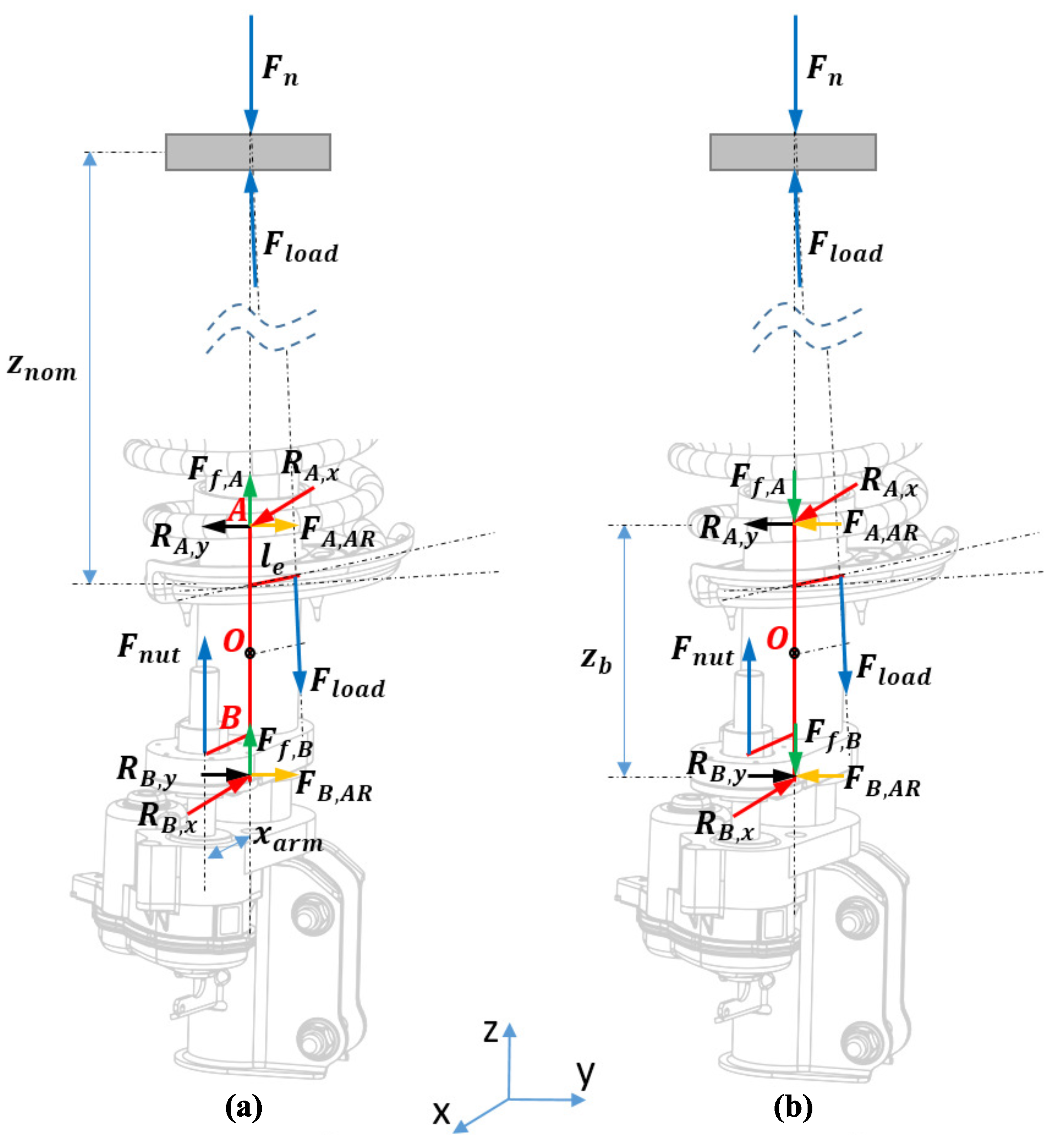
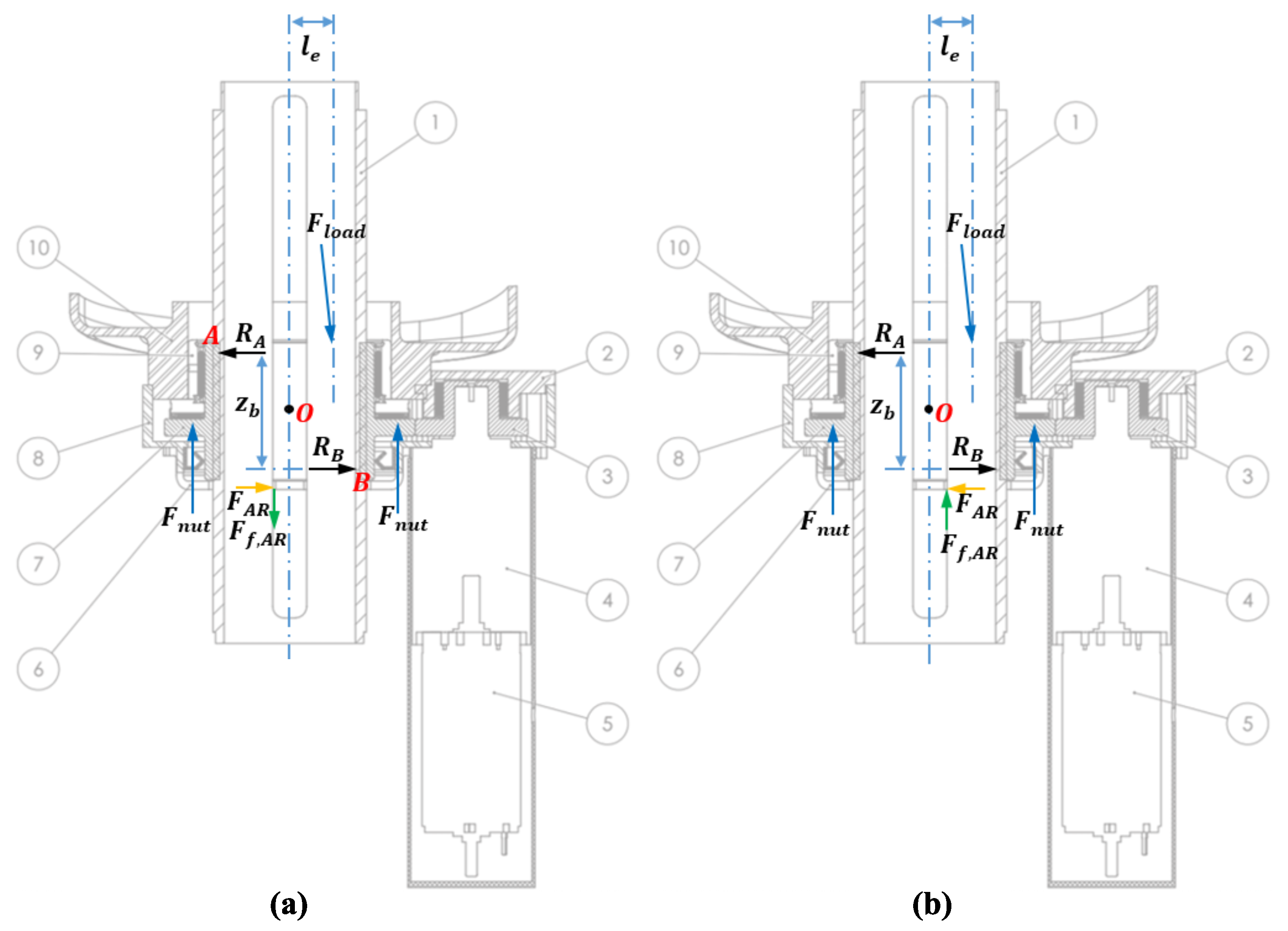
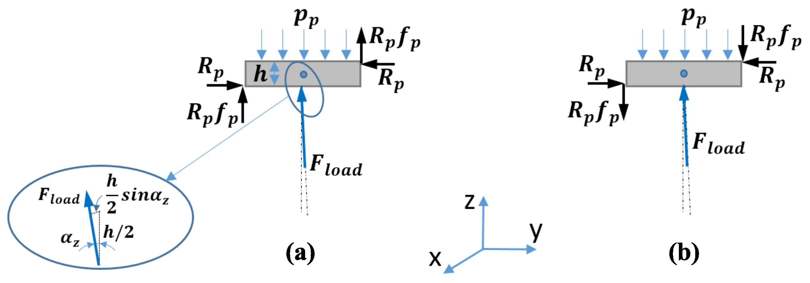
3.1. Eccentric Screw System Model

The forces acting on the height adjustment system with eccentric screw are shown in Figure 5. The load F load is generated due to the sprung mass F n , and it is applied to the upper spring holder. This force is transmitted to the lower spring holder through the spring. As it is known, the spring symmetry axis and the shock absorber rod axis are installed with some offset to reduce the hysteresis force on the walls of the shock absorber [30]. This offset and the application of the force F load with some inclination provides a bending moment on the lower spring holder. This bending moment is balanced in two bushings, thus producing friction losses during motion.
In the modeling process, the reference frame was chosen such that the Z axis coincided with the rod axis and the X axis coincided with the line connecting the rod and the power screw axes (Figure 5). The Y axis lay on the wheel hub mid-plane, which represented the Y Z plane. The original position of the lower spring holder of unmodified suspension was assumed to be a nominal position of the system. Points A and B are located at the mid-plane of two bushings on the center axis of the shock absorber. In the following, equations show the symbol “±”, where the plus sign was used for the lifting phase and the minus sign corresponded to the lowering phase. The equilibrium of the forces and moments are written for the lower spring holder, the sliding element, and the upper arm, which are welded to form a unique body (Figure 4). Then, the equilibrium of moments in the X Z plane around point O located at the middle of the two bushings is the following:
F nut x arm + F load l e z nom ± z + z b / 2 z nom ± z cos γ XZ = R A , x z b
F nut is the force developed at the power screw to lift or lower the nut, x arm is the distance between the centers of the power screw and the shock absorber tube, l e is the offset measured at the level of the lower spring holder (is not in any of the reference planes), z nom is the distance between mid-planes of upper and lower spring holders in nominal position, z is the spring holder vertical displacement during the actuation, z b is the vertical distance between two bushings (i.e., the distance between points A and B), γ XZ is the angle between the arm l e and the X Z plane, and R A , x is the reaction force in the X Z plane at points A and B (assumed to be equal). As a result, Equation (5) allows one to calculate the component of reaction forces in bushings A and B in the X Z plane.
The equilibrium of moments around point O in the Y Z plane is governed by Equation (6). It should be noted that the force F nut does not contribute to this equilibrium, as the force is in X Z plane.
F load l e z nom ± z + z b / 2 z nom ± z sin γ XZ = R A , y z b
The resulting reactions on the bushings R A and R B are computed from previously found components in two planes (Equations (5) and (6)) by assuming their equality:
R A = R A , x 2 + R A , y 2
Equilibrium of the forces in the Z axis reveals the force F nut required on the power screw. The force on the nut is composed of the component of the force F load in the Z axis and friction forces on the bushings that oppose the motion. Therefore, the force F nut is different in the lifting and lowering phases because the friction forces due to reactions R A and R B have different directions, while F load is always pointing downwards:
F nut = F load cos α z ± 2 R A f b
where α z is the inclination angle of the load F load with respect to the vertical axis Z and f b is the sliding friction coefficient on the bushings.
The torque on the nut T nut is balanced on the anti-rotation system and then accepted by the bushings at points A and B. Therefore, T nut produces additional reactions on the bushings F A , AR and F B , AR (assumed to be equal). These two reactions have the same direction and, hence, do not contribute to the moment around the point O. The arm of the anti-rotation force F A , AR is equal to the distance x arm , which is relatively long; therefore, the vertical friction forces due to these reactions have a small influence on the overall friction losses and can be neglected.
The torque of the electric motor T em required to develop the force F nut is computed as below:
T em = F nut i s i g i gb η tot
The transmission passes through the ratios of the screw i s , the gear or belt drive unit i g , and the gearbox i gb . The total efficiency of the transmission in (2) is also accounted for.

3.2. Concentric Screw System Model

The forces acting on the height adjustment system with the concentric screw are shown in Figure 6. The resulting load F load from the spring is applied to the lower spring holder with an offset distance l e and at an inclination. The force F load induces vertical forces and bending moments around point O. Furthermore, the anti-rotation force generates the friction force which opposes the motion (Figure 6).
Equilibrium of bending moments due to offset application of the load, assuming R A = R B , can be written as follows:
F load l e z nom + z b / 2 z nom = R A z b
These reactions create an additional friction torque T f , b on the power screw threads. It is assumed that the reactions are applied at the mean diameter d m of the power screw thread surface with the friction coefficient f s . Hence, the equation of the friction torque due to bending is as shown:
T f , b = R A d m f s
The total torque required to develop the vertical lifting or lowering force at the power screw level is derived from the applied load and the friction force on the anti-rotation system:
T f , s = F load ± F f , AR i s η s
The power screw efficiency also varies in these phases; hence, instead of η s , the corresponding values of η s , lift or η s , lower were used. The friction force F f , AR developed on the anti-rotation system due to reaction torque generated to balance the torque T nut can be computed as follows:
F f , AR = T nut d m / 2 f AR
The total torque required at the nut level, then, was computed as a sum of the friction torque T f , b due to the bending and the actuation torque required on the power screw T f , s :
T nut = T f , b + T f , s
Then, the torque required on the electric motor level can be computed using the transmission ratios and the efficiencies of the path:
T em = T nut i g i gb η g η gb
A proper subset of the previously described expressions leads to the electric motor torque T em for both eccentric and concentric screw systems. The actuation current I em , the rotational speed ω em , and the angular displacement θ em of the electric motor were obtained by setting, as input, the electric motor torque T em and the power supply voltage V DC to the state-space formulation:
ω ˙ em ω em I ˙ em = 0 0 k t / J eq 1 0 0 k e / L 0 R / L ω em θ em I em + 0 1 / J eq 0 0 1 / L 0 V DC T em
where k e is the electric motor speed constant, k t is the electric motor torque constant, J eq is the equivalent moment of inertia of rotating and translating elements, and L and R are the inductance and the resistance of the motor winding, respectively.
The angular displacement of the electric motor θ em can be converted into the linear displacement u z of the lower spring holder:
u z = θ em i gb i g i s
where the speed reduction ratio of the power screw–nut mechanism is given as i s = 2 π / p .

4. Experimental Results

The prototype of the eccentric screw system was built for experimental investigation of the system and validation of the developed model. In addition, the testbed allowed performance of accelerated experiments to identify critical components in terms of fatigue and wear. However, this work does not focus on the results of experimental fatigue analysis, which can be a topic of future efforts.
Figure 7 shows the prototypes of eccentric and concentric screw systems used during the tests. The prototype of the eccentrically mounted screw system was assembled on a McPherson shock absorber of a 4x4 SUV. For comparison purposes, the novel eccentric screw solution was compared to the prototype with a concentrically mounted screw system from a previous study [11]. The experimental setup and the obtained results are discussed hereafter.

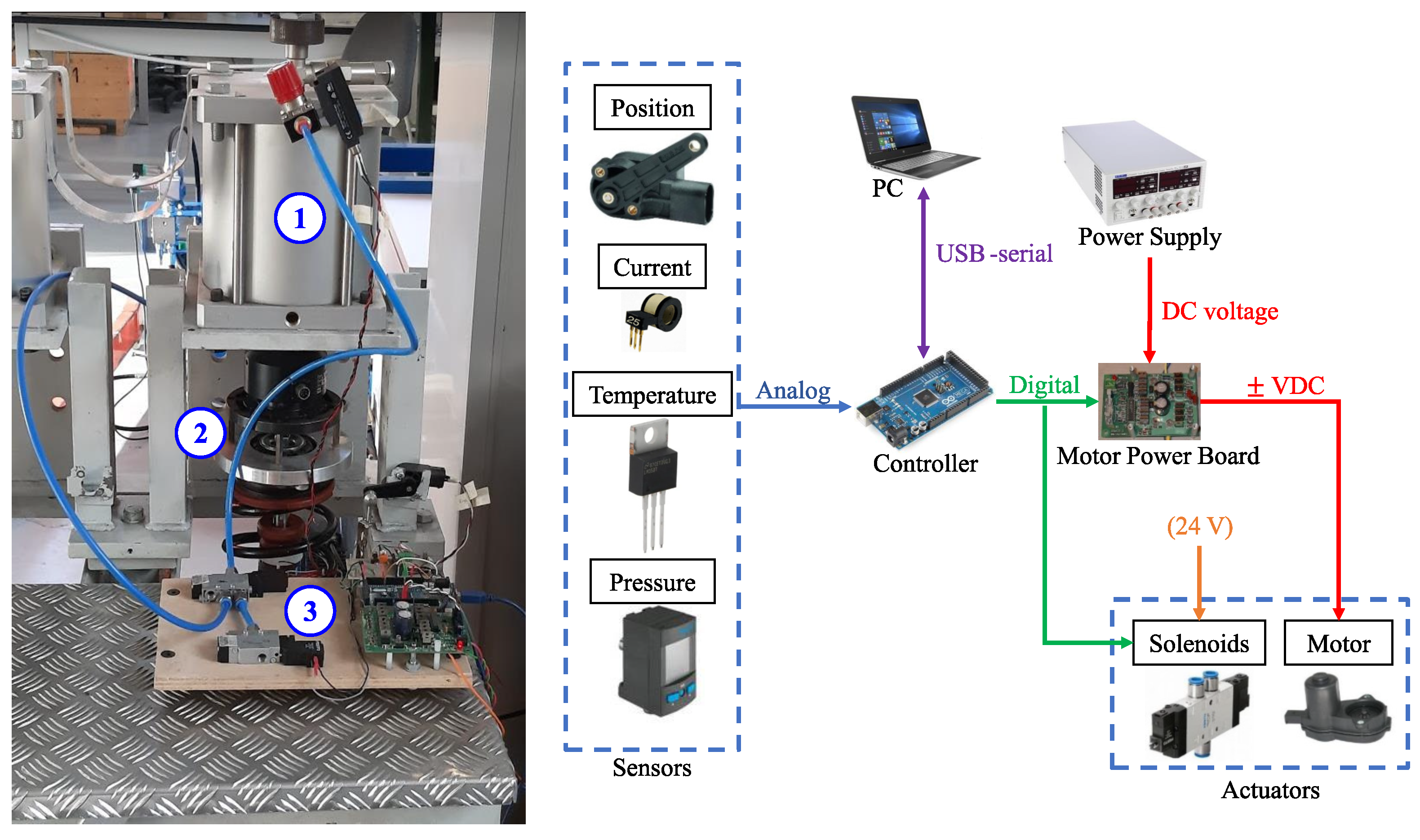
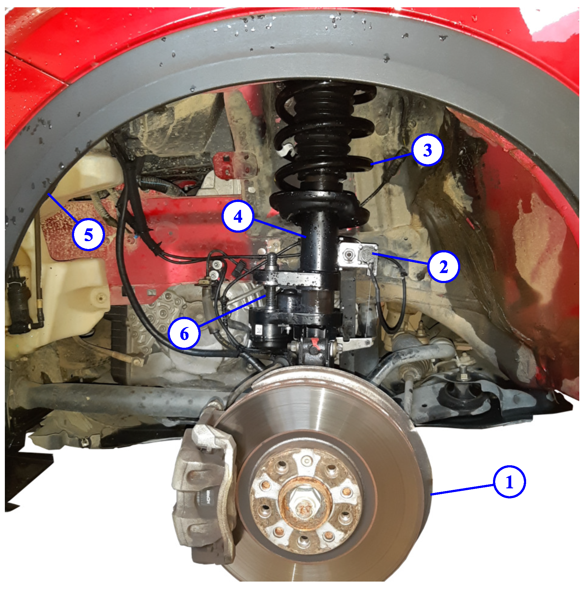
4.1. Experimental Setup

The experiments were conducted on the test bench shown in Figure 8. The test bench consisted of a pneumatic cylinder and a piston made of aluminum, which simulated the load of the sprung mass acting on the upper spring holder. The pressure inside the pneumatic cylinder was controlled by an external air compressor and a set of valves to obtain constant loading. A custom control board was used to control the moving lever position and the air pressure inside the pneumatic cylinder, and to monitor the current and the temperature of the motor. The main components of the control board are presented in Figure 8 on the right. The position of the height adjustment system was measured by a HELLA™ angular position sensor (range: ± 40 deg , sensitivity: 56 mV / deg , accuracy: ±1%) [31]. The motor current was measured by an Amploc™ AMP25 Hall sensor (sensitivity 37 mV / A , accuracy: ±2%) [32]. The electric motor is supplied by a power stage which consisted of an OSMC™ H-bridge board (IRFB3207 switches, conduction resistance: R on = 2.6 m Ω at ambient temperature) supplied by a 12 V DC bus. The pressure inside the cylinder was measured by a FESTO™ SDE1 pressure sensor ( 0 ÷ 6 bar, accuracy ±2%) [33]. Two on–off solenoid valves (FESTO™ MEBH-3/2-1/8-B [34]) were actuated to guarantee the desired pressure range. The pressure control in the cylinder was performed in a feed-forward way. The first solenoid valve opened to let air out into the atmosphere, while the second increased the cylinder pressure using a supply from an air compressor with a 0.03 m 3 reservoir and a pressure of 4 bar. The temperature of the motor case was measured by a Texas Instruments™ LM35TD sensor ( 0 ÷ 100 °C, sensitivity: 10 mV /°C, accuracy: ±1.5%) [35]. To avoid permanent damage due to overheating, the motor was disabled during the tests when the temperature of its case reached 50 °C. The control algorithm for continuous fatigue tests and failure detection was implemented on an Arduino™ Mega 2560 microcontroller [36], while a PC with a custom graphical user interface (GUI) was used for data acquisition and monitoring.
Due to the inclined application of the force F load at an angle α z with respect to the Z axis (see Figure 9), the pneumatic loading system presented slight hysteresis caused by a reaction on the piston wall. Therefore, the force F load differed from the force applied by the pressure in the pneumatic cylinder by the value of the friction force developed on the walls. The reaction on the piston wall R p can be computed using the equilibrium of moments around the center point of the piston of a height h:
F load h 2 sin α z = R p h
The friction force due to the reaction on the piston side surfaces with the friction coefficient f p is the following:
F f , p = 2 R p f p
Subsequently, the equilibrium of the forces on the Z axis can be written using the load applied to the spring, the force due to the pressure in the cylinder, and the friction force on its walls:
F load cos α z F f , p = p p A p
where p p is the pressure inside the pneumatic cylinder and A p is the piston area. The direction of the friction force on the piston walls F f , p is different in the lowering and the lifting phases. In (20), the plus and minus signs are used for the lowering and the lifting phases, respectively. Consequently, the value of the force F load transmitted to the lower spring holder during the tests can be computed.

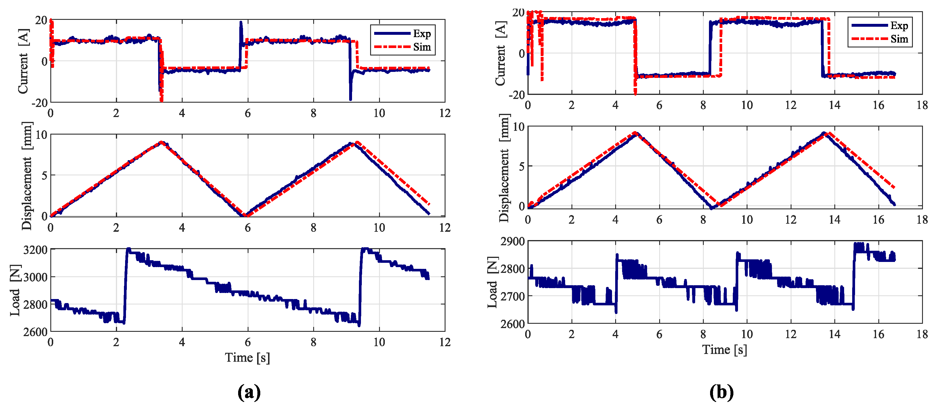
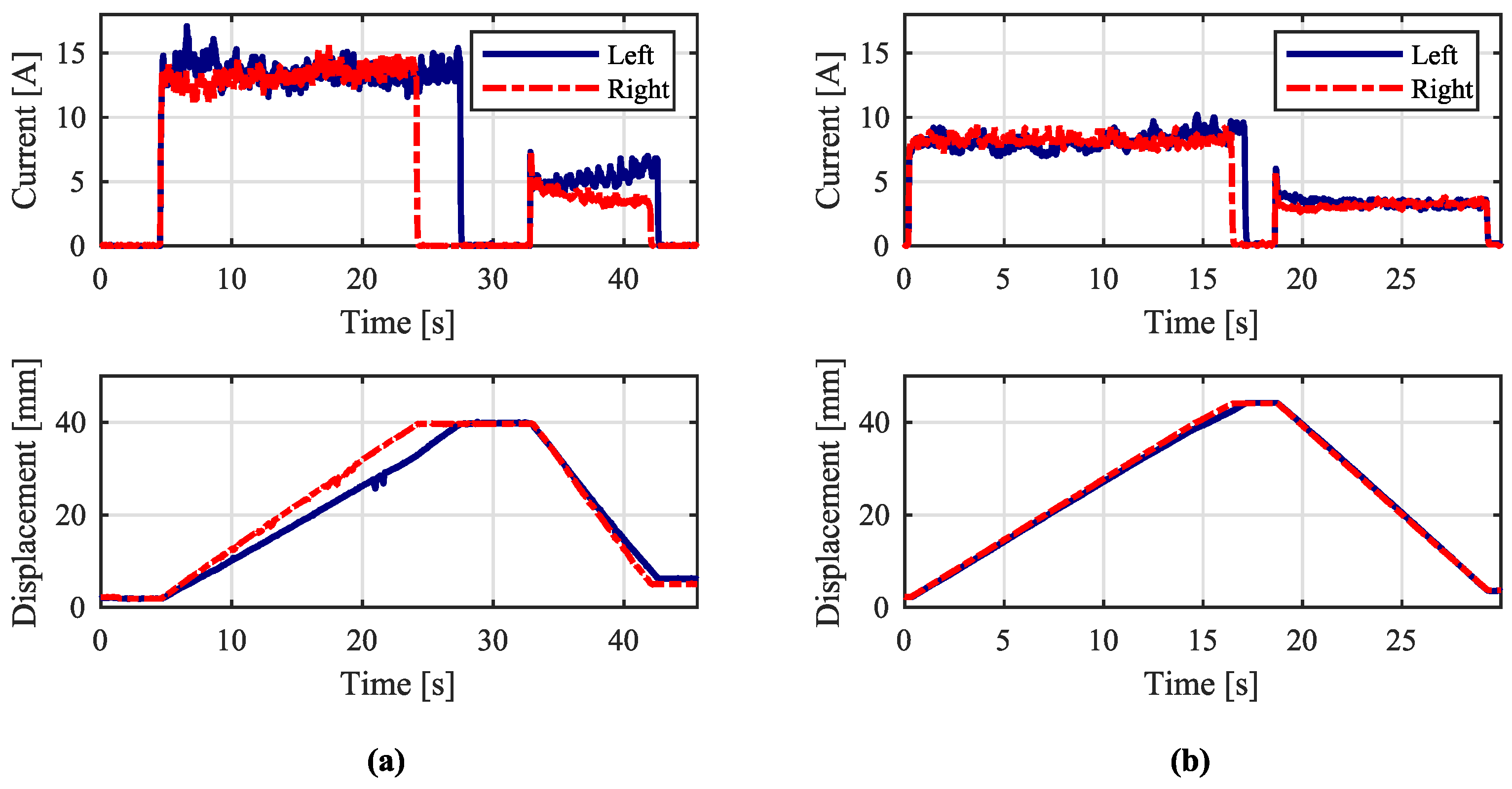
4.2. Experiments on Testbed

The performance of both prototypes was assessed using the setup described in Section 4.1. Figure 10 shows the time history of the actuator position, its current absorption, and the force developed in the pneumatic cylinder during the lowering and lifting phases. During the tests, the displacement and the load were limited to 10 mm and 3000 N , respectively. This force required 0.95 bar pressure in the pneumatic cylinder. However, the pressure in the pneumatic cylinder varied between 0.84 and 1.02 bar , with the mean value being 0.93 bar . This means that pressure roughly corresponded to a force applied on the upper spring holder equal to 2900 N .
A numerical model in the MATLAB/Simulink™ environment was developed. The simulation was performed on both systems, replicating the same conditions of the experiments and using as an input the time history of the pressure recorded during the tests. To simulate the dynamic behavior of both systems, an ode15s variable-step solver was used in the Simulink model with a maximum step size of 0.02 s . Figure 10 shows a favorable match between the experimental and simulation results for current absorption. In the lifting phase, the simulation and experimental results for actuation speed showed good similarity. However, for the lowering phase, the simulated actuation speed was slightly higher than the one obtained experimentally. This leads to a slight shift in time of the two displacement plots in Figure 10. This can be linked to the fact that the value of the friction coefficient is assumed to be equal to 0.25 in the anti-rotation and power screw–nut mechanism. Furthermore, the values of the torque ( k t ) and back EMF ( k e ) constants might differ from the ones used in the simulation. The parameters of the different components of both systems used in the simulation are summarized in Table 2.
It can be observed in Figure 10 that the load behaves more smoothly in the case of the eccentric system, which is linked to the leakage in the pneumatic cylinder. The concentric system moves with a certain degree of impulsive forces due to the presence of sawing effect between the screw thread and the anti-rotation system tooth. The eccentric screw system is free of this kind of impulse; hence, the leakage occurs gradually.
The values of sliding friction coefficients of the bushings ( f b ) and the piston of the pneumatic cylinder ( f p ) were selected from the material handbook typical data. The values of the sliding friction coefficient on screw–nut surfaces ( f s ) and on the anti-rotation system ( f AR ) were determined from previous experience with this type of actuator [11].
Experimental results show that the actuation speed to lift the load is 1.81 mm / s in the case of the concentric screw and 2.69 mm / s in the case of the eccentric solution. The load-lowering speeds of the systems are higher, as the load, in this case, helps the motor: 2.7 mm / s and 3.7 mm / s for the concentric and the eccentric screws, respectively. At these values of speed, the damping force of the shock absorber is negligible, considering viscous damping coefficient values in the range between 10 and 20 Ns / mm [37,38].
The average currents required to lift the applied load for the concentric and the eccentric screw systems are about 14.7 A and 10 A , respectively. By converse, lowering demands 10 A and 4.4 A , respectively. Assuming a constant battery voltage V DC = 12 V , the average power required to lift the load with the concentric system is around 176 W and for the eccentric is 120 W . The lowering phase of the load requires 120 W on the concentric system and 53 W on the eccentric one. One entire cycle with lifting and subsequent lowering requires, on average, 300 W for the concentric system and 175 W for the eccentric one. To perform a cycle of 10 mm of lowering and equal lifting, the systems require 0.393 Wh (concentric) and 0.164 Wh (eccentric) of energy. The average values of the main performance indicators are summarized in Table 3.

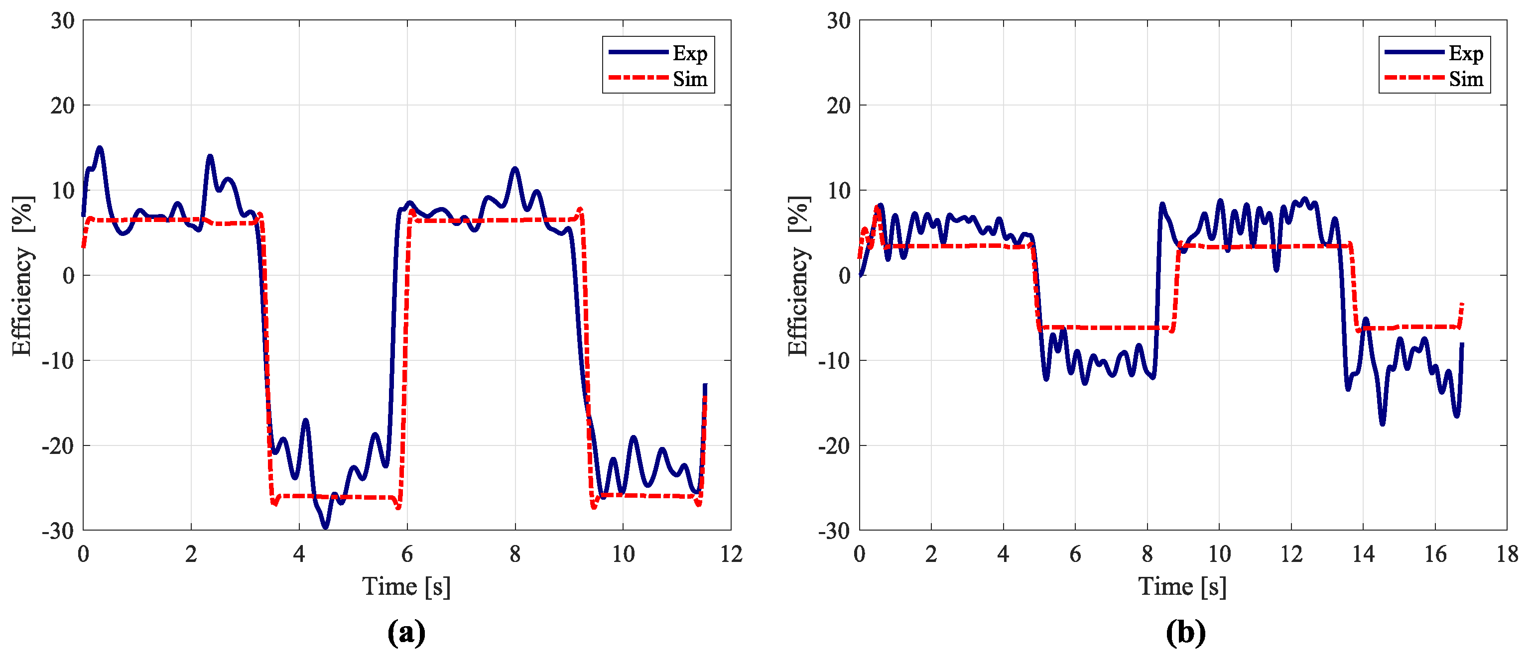
4.3. Efficiency Analysis

The overall efficiencies of the systems η ov from power supply to the load can be defined using (21). In this case, the output power P out is a mechanical power, the input power P in is an electrical power, and v load is an actuation speed:
η ov = P out P in = F load v load V DC I DC
The efficiency path includes the efficiency of the electric motor, the gearbox, the gear or the belt drive unit, and the power screw. Moreover, it takes into account the losses due to the anti-rotation system and the sliding surfaces. The absolute average values of the overall efficiency for the lifting phase are 3.4% and 6.5% for the concentric and the eccentric systems, respectively. For the lowering phase, these values are higher, equal to 6.2% and 26%. Table 3 also summarizes the values of overall efficiencies. Figure 11 depicts the comparison of the experimental (solid line) and the simulation (dashed line) results of overall efficiencies obtained using (21).
Although the efficiencies of the power screw–nut mechanism in the two cases are very close to each other (Figure 3), the overall efficiencies of the eccentric and the concentric screw systems differ substantially. The higher overall efficiency of the eccentric screw system can be attributed to the anti-rotation and balancing of the bending moment due to the offset application of the load. The friction force developed in the anti-rotation of the eccentric system is around 36 N , while, for the concentric screw system, this force is around 370 N . This is mainly linked to the fact that, in the eccentric solution, the anti-rotation torque is balanced at a larger distance. The friction force due to the bending moment for the eccentric screw system is about 1150 N , compared to 450 N for the concentric system. However, in the case of the eccentric screw system, the bending moment is balanced on the two bushings, whereas, on the concentric screw, it is balanced on the screw threads. Therefore, the friction forces due to this bending require a higher torque (the term T f , b in (14)) from the electric motor both in lifting and in lowering phases for the concentric screw system. The results of the simulation show that the torque required to overcome the friction force due to bending at the screw level is about 2.7 Nm for the eccentric and 12 Nm for the concentric screw systems. Furthermore, the friction force on the bushings for the eccentric screw system ( ± 2 R A f b in (8)) requires a torque during lifting and helps the motor during lowering by reducing the value of F load . Hence, the large difference in the overall efficiency of the eccentric screw in the lifting and lowering phases can be attributed to this feature. Additionally, in the eccentric system, anti-rotation is achieved by the contact between a bronze bushing and a rectified surface. In the concentric counterpart, it is difficult to use low-friction interfaces to yield the anti-rotation.

5. Vehicle Tests

The eccentric screw prototype characterized in Section 4.2 was replicated and installed on all four corners of a class D demo vehicle. In this car, front and rear suspensions presented MacPherson struts. Packaging analyses were carried out to avoid interference with brake calipers, anti-roll bar linkages, and other suspension components. The front suspension required particular attention due to steering. Figure 12 depicts the installation of an eccentric screw prototype on the rear left corner.
All prototypes were equipped with draw-wire potentiometers as position sensors (Micro-Epsilon™ WPS150MK30 [39]). For actuation purposes, the same solution used in the testbed (Section 4.1) was implemented on the four corners. Additional wireless functionality was added to operate the four actuators from a graphical interface on a handheld device. These power modules were connected to the 12 V battery of the vehicle. The temperature of the prototypes was also monitored to avoid overloading the electric machines that power the actuators. It should be noted that the height adjustment process can be performed both during a vehicle standstill and while it is traveling.
To demonstrate functionality, Figure 13 depicts subsequent lifting and lowering phases on the four corners while the car was traveling on an urban straight road at approximately 35 km / h . The collected data for both current and position measurements were filtered in post-processing with a zero-phase discrete low-pass filter. The cutoff frequency (5 Hz ) was selected well above the mechanical time constant of the system. Results show that right and left rear actuators behave very similarly. The lifting phase accomplishes a stroke of 42 mm in 17 s , with an average current absorption of 8.6 A . Lowering returns back to the original position in only 10.5 s and absorbs a lower current (3.4 A ). This difference between actuation phases is due to the weight of each corner, which opposes lifting and aids lowering.
The influence of the weight is seen clearly in the results of the front axle, where right and left actuators differ, especially in the lifting phase. Both actuators accomplish a lifting stroke of 42 mm and absorb 13.3 A , on average. The right actuation duration lasts 20 s , while the left actuation is 3 s longer. Lowering is almost equal for both actuators in terms of duration (9 s ). Average current absorption starts at 5 A in both cases. However, this value tends to increase slightly for the left corner, whereas it decreases for the right one.
Results on front and rear axles demonstrate the uneven distribution of mass due to the installation of the engine block and other heavy components towards the front. In addition, the presence of the driver yields unsymmetrical results, especially seen in the front axle.
In a laboratory environment, acoustic behavior was measured at 1 m of distance from the power screw. Sound pressure levels ranged from 66.4 to 71 dB during actuation, depending on the level of lubrication of the screw–nut assembly. However, during vehicle operation, this sound was partially masked by vehicle noise sources, such as the engine and wheel rolling.

6. Conclusions

Vehicle height adjustment suspensions can potentially offer improved fuel efficiency and CO2 emission reduction. Other advantages are the adaptability to different driving styles and conditions, as well as the passenger convenience when boarding and unboarding the vehicle.
In this work, two electromechanical height adjustment systems with concentrically and eccentrically mounted screws were compared. In particular, from both actuators, the latter shows a novel approach to guarantee anti-rotation. The parameters of these systems were identified and prototypes were built for further experimental investigations. The tests were performed on the suspension testbench designed for accelerated measurements. Detailed models of these two systems were developed to assess their performance numerically. These models take into account the losses due to anti-rotation systems and the bending due to the offset application of the load on the spring holders.
The experimental tests allowed us to measure the power absorption of the systems required to perform actuation cycles. In terms of power draw, the novel eccentric solution demonstrated superior performance during both the lifting and lowering phases. Furthermore, the overall efficiencies of such systems were defined experimentally and compared to the results obtained from the developed models. Accordingly, the eccentric system demonstrated a favorable improvement with respect to the concentric alternative in this regard. Despite the similar efficiency of the screw system alone in both prototypes, the overall performance differed substantially in favor of the eccentric actuator. The higher efficiency of the eccentric screw system is attributed to the inherent anti-rotation system and the proper balance of the bending moment.
The novel eccentric screw solution was implemented in four corners of a demo vehicle. Functionality was demonstrated with the vehicle in motion by lifting and lowering the four corners. Favorable results in terms of actuation speed and absorbed current were obtained. As expected, these results showed uneven performance due to the weight distribution of the vehicle.
Future work can be devoted to analyzing the fatigue of critical components and to investigating the change in ride comfort and handling due to the height adjustment feature.

Author Contributions

Conceptualization, S.R., L.M.C.M., R.G., R.M., N.A. and A.T.; Data curation, S.R. and L.M.C.M.; Formal analysis, S.R. and L.M.C.M.; Investigation, S.R., L.M.C.M., R.G., R.M., N.A. and A.T.; Methodology, S.R., L.M.C.M., N.A. and A.T.; Resources, S.R., L.M.C.M., R.G. and R.M.; Software, S.R. and L.M.C.M.; Supervision, N.A. and A.T.; Validation, S.R., L.M.C.M. and R.M.; Writing—original draft, S.R. and L.M.C.M.; Writing—review & editing, R.G., R.M., N.A. and A.T. All authors have read and agreed to the published version of the manuscript.

Funding

This research received no external funding.

Data Availability Statement

Not applicable.

Acknowledgments

The present work was supported by Marelli Suspension Systems Italy S.p.A. The authors would like to thank Ing. Giordano Greco and Ing. Piero Monchiero for providing all necessary data and support during the design process and testing phases.

Conflicts of Interest

The authors declare no conflict of interest.

Abbreviations

The following abbreviations are used in this manuscript:
CO 2 Carbon dioxide
DCDirect Current
SUVSport Utility Vehicle
GUIGraphical User Interface

Nomenclature

d m Mean diameter of the screw
d min Minor (root) diameter of the screw
d tube Diameter of the shock absorber tube
f b Sliding friction coefficient on the bushings
f p Sliding friction coefficient on the piston of the pneumatic cylinder
f s Sliding friction coefficient on screw–nut surfaces
f AR Sliding friction coefficient on the anti-rotation system
hHeight of the piston of the pneumatic cylinder
i g Speed reduction ratio of the parallel axis speed reducer
i gb Speed reduction ratio of the planetary gearbox
i s Speed reduction ratio of the screw–nut mechanism
i total Total speed reduction ratio of the parallel axis speed reducer, planetary gearbox
and screw–nut mechanism
k e Motor back EMF constant
k t Motor torque constant
l e Offset measured at the level of the lower spring holder
pScrew pitch
p p Pressure inside the pneumatic loading cylinder
sDiametric thickness of the power screw body
t 50 mm Time to cover 50 mm distance
t max Maximum travel time requirement
u z Spring holder vertical displacement
v load Actuation speed of the load
x arm Distance between centers of the power screw and the shock absorber tube
z b Vertical distance between two bushings
z nom Distance between mid-planes of upper and lower spring holders in nominal position
A p Piston area of the pneumatic loading cylinder
F f , p Friction force on the piston side surfaces
F f , AR Friction force on the anti-rotation system
F load Load on the lower spring holder
F n Static load due to the vehicle weight
F nut Load developed on the power screw
I em Current to actuate the electric motor
I max Maximum actuation current of the electric motor
I ss Steady state current absorption
J em Moment of inertia of the electric motor’s rotating parts
J eq Equivalent moment of inertia of the rotating and translating elements
J gb Moment of inertia of the planetary gearbox
J p Moment of inertia of the parallel axis speed reducer
J s Moment of inertia of the screw
LInductance of the motor winding
P em Nominal power of the electric motor
P in Input electric power
P out Output power from the height adjustment system
P req Required power of the electric motor
RResistance of the motor winding
R p Reaction force on the piston wall
R A Reaction force in bushings at point A
R A , x Reaction force in bushings in the XZ plane
R A , y Reaction force in bushings in the YZ plane
R B Reaction force in bushings at point B
T em Torque on the electric motor shaft
T em , n Nominal torque of the electric motor
T f , b Friction torque due to bending
T f , s Torque on the power screw required for actuation of the load
T nut Total torque required on the nut for actuation and to overcome frictions
T req Required torque on the electric motor shaft
V DC Supply voltage of the vehicle battery
α Power screw thread angle
α z Inclination angle of the load F load with respect to the Z (vertical) axis
γ XZ Angle between the arm l e and XZ plane
η g Efficiency of the speed reducer or belt drive
η gb Efficiency of the planetary gearbox
η ov Efficiency of the overall conversion (from electric to mechanical actuation)
η s Efficiency of the power screw
η s , lift Efficiency of the power screw in lifting phase
η s , lower Efficiency of the power screw in lowering phase
η tot Overall efficiency of the transmission path
λ Power screw lead angle
ω em Angular speed of the electric motor shaft
ω n Angular speed of the electric motor shaft at nominal power
ϕ Friction angle of the power screw
θ em Angular displacement of the electric motor shaft
θ ˙ em Angular velocity of the electric motor shaft
θ ¨ em Angular acceleration of the electric motor shaft
ω req Required angular velocity of the electric motor shaft

References

  1. International Energy Agency. Key Trends in CO2 Emissions. Excerpt from: CO2 Emissions from Fuel Combustion (2015 Edition); IEA: Paris, France, 2015. [Google Scholar]
  2. Ott, T.; Onder, C.; Guzzella, L. Hybrid-electric vehicle with natural gas-diesel engine. Energies 2013, 6, 3571–3592. [Google Scholar] [CrossRef] [Green Version]
  3. Gabriel-Buenaventura, A.; Azzopardi, B. Energy recovery systems for retrofitting in internal combustion engine vehicles: A review of techniques. Renew. Sustain. Energy Rev. 2015, 41, 955–964. [Google Scholar] [CrossRef]
  4. Howell, J.; Sherwin, C.; Passmore, M.; Le Good, G. Aerodynamic Drag of a Compact SUV as Measured On-Road and in the Wind Tunnel. SAE Trans. 2002, 111, 583–590. [Google Scholar]
  5. Genta, G.; Morello, L. The Automotive Chassis: Volume 2: System Design; Springer Science & Business Media: Dordrecht, The Netherlands, 2009; pp. 146–149. [Google Scholar]
  6. CO2 Emission Standards for New Cars and Vans. Available online: https://www.europarl.europa.eu/RegData/etudes/BRIE/2022/698920/EPRS_BRI(2022)698920_EN.pdf (accessed on 26 May 2023).
  7. EU CO2 Emission Standards for Passenger Cars and Light-Commercial Vehicles. Available online: https://theicct.org/sites/default/files/publications/ICCTupdate_EU-95gram_jan2014.pdf (accessed on 26 May 2023).
  8. Faraj, J.; Harika, E.; Ramadan, M.; Ali, S.; Harambat, F.; Khaled, M. Effect of Underhood Architecture on Aerodynamic Drag—Suggestion of New Concepts for Fuel Consumption Reduction. Int. J. Automot. Technol. 2020, 21, 633–640. [Google Scholar] [CrossRef]
  9. Strassberger, M.; Guldner, J. BMW’s dynamic drive: An active stabilizer bar system. IEEE Control Syst. 2004, 24, 28–29. [Google Scholar]
  10. van der Westhuizen, S.F.; Els, P.S. Slow active suspension control for rollover prevention. J. Terramechanics 2013, 50, 29–36. [Google Scholar] [CrossRef] [Green Version]
  11. Amati, N.; Tonoli, A.; Castellazzi, L.; Ruzimov, S. Design of electromechanical height adjustable suspension. Proc. Inst. Mech. Eng. Part D J. Automob. Eng. 2017, 232, 1253–1269. [Google Scholar] [CrossRef] [Green Version]
  12. Cogotti, A. A Parametric Study on the Ground Effect of a Simplified Car Model; SAE Technical Paper Series; SAE International: Warrendale, PA, USA, 1998. [Google Scholar] [CrossRef]
  13. Schuetz, T. Aerodynamics of Road Vehicles; SAE International: Warrendale, PA, USA, 2016. [Google Scholar]
  14. Semeraro, F.F.; Schito, P. Numerical Investigation of the Influence of Tire Deformation and Vehicle Ride Height on the Aerodynamics of Passenger Cars. Fluids 2022, 7, 47. [Google Scholar] [CrossRef]
  15. Dong, T.; Minelli, G.; Wang, J.; Liang, X.; Krajnović, S. The Effect of Ground Clearance on the Aerodynamics of a Generic High-Speed Train. J. Fluids Struct. 2020, 95, 102990. [Google Scholar] [CrossRef]
  16. Temporelli, R.; Micheau, P.; Boisvert, M. Control of an electromechanical clutch actuator by a parallel Adaptive Feedforward and Bang-Bang controller: Simulation and Experimental results. IFAC-PapersOnLine 2017, 50, 4787–4793. [Google Scholar] [CrossRef]
  17. Dong, G.; Wang, F.; Meng, D.; Chu, H.; Hong, J.; Gao, B. Modeling and control of ball-ramp electromechanical clutch actuator for in-wheel AMT of electric vehicles. Mech. Mach. Theory 2023, 180, 105129. [Google Scholar] [CrossRef]
  18. Jeong, S.-H.; Kim, K.-S. A 2-Speed Small Transmission Mechanism Based on Twisted String Actuation and a Dog Clutch. IEEE Robot. Autom. Lett. 2018, 3, 1338–1345. [Google Scholar] [CrossRef]
  19. Eskandary, P.K.; Angeles, J. The virtual screw: Concept, design and applications. Mech. Mach. Theory 2018, 128, 349–358. [Google Scholar] [CrossRef]
  20. Michel, W. Height Adjustment on a Wheel Suspension for Motor Vehicles. U.S. Patent US 7,784,800, 31 August 2010. [Google Scholar]
  21. Michel, W. Wheel Suspension for Motor Vehicles. U.S. Patent US 8,317,003, 27 November 2012. [Google Scholar]
  22. Bruno, W.; Conti, P.A.; Greco, G.; Amati, N.; Galluzzi, R.; Ruzimov, S.; Tonoli, A. Damper and Spring Unit for a Vehicle Suspension Provided with an Electro-Mechanical Adjustment Device for Adjusting the Vertical Position of the Spring. WIPO Patent WO2019097461, 23 May 2019. Available online: https://patentscope.wipo.int (accessed on 1 June 2023).
  23. Maxon Motor. Product Specifications. Available online: http://www.maxonmotor.com/maxon/view/product/273752 (accessed on 26 May 2023).
  24. Tonoli, A.; Amati, N.; Impinna, F.; Detoni, J.G.; Ruzimov, S.; Gasparin, E.; Abdivakhidov, K. Influence of dry friction on the irreversibility of cycloidal speed reducer. In Proceedings of the World tribology Congress, Torino, Italy, 8–13 September 2013. [Google Scholar]
  25. Meng, Y.; Wu, C.; Ling, L. Mathematical modeling of the transmission performance of 2K–H pin cycloid planetary mechanism. Mech. Mach. Theory 2007, 42, 776–790. [Google Scholar] [CrossRef]
  26. Raffone, E. An Electric Parking Brake Motor-On-Caliper actuator model for robust drive away control design. IFAC-PapersOnLine 2017, 50, 980–986. [Google Scholar] [CrossRef]
  27. Laus, L.P.; Simas, H.; Martins, D. Efficiency of gear trains determined using graph and screw theories. Mech. Mach. Theory 2012, 52, 296–325. [Google Scholar] [CrossRef]
  28. Budynas, R.G.; Nisbett, J.K. Shigley’s Mechanical Engineering Design, 8th ed.; McGraw Hill: New York, NY, USA, 2006; pp. 405–406. [Google Scholar]
  29. Körner, F.; Mayer, R. Analysis and characterization of the friction of vehicle body vibration dampers. Automot. Engine Technol. 2020, 5, 79–90. [Google Scholar] [CrossRef]
  30. Genta, G.; Morello, L. The Automotive Chassis: Volume 1: Component Design; Springer Science & Business Media: Dordrecht, The Netherlands, 2009; pp. 144–146. [Google Scholar]
  31. Rotation Angle Sensors. Available online: https://www.hella.com/resources-soe/assets/documents_global/1871_Brief_info_Angular_Sensors_HELLA_EN.pdf (accessed on 26 May 2023).
  32. AMP25 Open Loop Hall Effect Sensor. Available online: https://amploc.com/products/amp25-open-loop-hall-effect-sensor (accessed on 26 May 2023).
  33. Pressure Sensors SDE1, with Display. Available online: https://www.festo.com/cat/en-gb_gb/data/doc_ENUS/PDF/US/SDE1_ENUS.PDF (accessed on 26 May 2023).
  34. Air Solenoid Valve MEBH-3/2-1/8-B-230AC. Available online: https://us.rs-online.com/m/d/0b5bd1adfdc27e97aaf2970f6091f14a.pdf (accessed on 26 May 2023).
  35. LM35 Precision Centigrade Temperature Sensors. Available online: https://www.ti.com/lit/ds/symlink/lm35.pdf (accessed on 26 May 2023).
  36. ARDUINO MEGA 2560 REV3. Datasheet. Available online: https://docs.arduino.cc/static/b041a982c2b71c2b39349c223c58d72e/A000067-datasheet.pdf (accessed on 26 May 2023).
  37. Zuo, L.; Zhang, P.S. Energy Harvesting, Ride Comfort, and Road Handling of Regenerative Vehicle Suspensions. J. Vib. Acoust. 2013, 135, 011002. [Google Scholar] [CrossRef]
  38. Liu, J.; Liu, J.; Zhang, X.; Liu, B. Transmission and energy-harvesting study for a novel active suspension with simplified 2-DOF multi-link mechanism. Mech. Mach. Theory 2021, 160, 104286. [Google Scholar] [CrossRef]
  39. Micro-Epsilon Draw Wire Displacement Sensors. Available online: https://www.micro-epsilon.com/download/products/cat-wiresensor/dax--wireSENSOR-MK30--en-us.html (accessed on 26 May 2023).
Figure 1. Different electromechanical height adjustment systems with lower spring holder actuation: (a) concentric [11] and (b) eccentric. Components: (1) upper spring seat, (2) spring, (3) shock absorber tube, (4) pinon gear, (5) gearbox, (6) onboard electric battery, (7) electric motor, (8) wheel hub, (9) power screw, (10) nut, (11) axial thrust bearing, (12) lower spring holder, (13) belt drive, (14) lower arm, (15) upper arm, (16) bushing, (17) guiding element. Note: Only additional or different elements are indicated with numbers for the eccentric system.
Actuators 12 00264 g001
Figure 2. Flowchart of the electromechanical design of the power screw actuation system.
Actuators 12 00264 g002
Figure 3. Contour plots of (a) the screw efficiency η s and (b) the electric motor torque T req required to drive the same static load F n . Design points of eccentric (circle) and concentric (square) systems are highlighted.
Actuators 12 00264 g003
Figure 4. Prototype of the front suspension actuator with eccentric screw shown in (a) 3D view of the components and (b) cross-section of the suspension. Components: (1) spring holder, (2) dust boot, (3) upper arm, (4) conical washer, (5) anti-rotation, (6) nut, (7) screw, (8) O-ring, (9) bronze bushing, (10) screw adapter, (11) axial needle bearing, (12) shock absorber tube, (13) lower arm, (14) retaining ring, (15) bushing, (16) guiding element, (17) spring, (18) shock absorber rod.
Actuators 12 00264 g004
Figure 5. Forces acting on the eccentric system during the (a) lowering and (b) lifting phases.
Actuators 12 00264 g005
Figure 6. Forces acting on the concentric system during the (a) lifting and (b) lowering phases [11]. Components: (1) screw, (2) casing cover, (3) pinion, (4) planetary gearbox, (5) DC motor.
Actuators 12 00264 g006
Figure 7. Two height adjustment systems under consideration: (a) eccentrically and (b) concentrically mounted screw systems.
Actuators 12 00264 g007
Figure 8. Experimental test bench layout and connection of the main components. Testbed subsystems: (1) pneumatic cylinder, (2) prototype, (3) control board.
Actuators 12 00264 g008
Figure 9. Free body diagram of the piston of the pneumatic loading system in the (a) lowering and (b) lifting phases.
Actuators 12 00264 g009
Figure 10. Comparison of the experimental (Exp, solid) and simulated (Sim, dash-dotted) results for the actuation systems: (a) eccentric and (b) concentric solutions.
Actuators 12 00264 g010
Figure 11. Comparison of the experimental (Exp, solid) and simulated (Sim, dash-dotted) efficiencies for the actuation systems: (a) eccentric and (b) concentric solutions.
Actuators 12 00264 g011
Figure 12. Eccentric screw prototype installed on the rear left corner of the vehicle. Components: (1) wheel hub, (2) draw-wire potentiometer, (3) suspension spring, (4) guiding element on shock absorber tube, (5) wheel arch, (6) power screw.
Actuators 12 00264 g012
Figure 13. Current and displacement behavior of four eccentric screw prototypes mounted on a demo vehicle running at 30 km / h on an urban road. Results for (a) front and (b) rear axles are illustrated. Uneven behavior is observable due to the weight distribution of the vehicle.
Actuators 12 00264 g013
Table 1. Main design requirements of the height adjustment systems.
FeatureSymbolConstraint
Static load F n ≥3 kN
Irreversibility limit η s <50%
Screw minor diameter * d min > d tube + s
Steady-state current I ss <15 A
Time to travel 50 mm t 50 mm <13 s
* Constraint used only for concentric screw solution.
Table 2. Parameters of the height adjustment systems used in the analysis.
CategoryParameterSymbolUnitConcentricEccentric
ScrewThread angle (ACME) α deg 14.514.5
Pitchp mm / rev 83
Mean diameter d m mm 5316
Electric motorNominal power P em , n W 9060
Nominal torque T em , n mNm 73.137.5
Nominal speed ω n r / min 65008944
Winding resistanceR Ω 0.3140.378
Winding inductanceL H 85200
Torque constant k t Nm / A 0.01940.0097
Back EMF constant k e Vs / rad 0.01940.0097
Supply voltage V DC V 1212
Speed reducerGearbox ratio i gb -81:150:1
Gearbox efficiency η gb %7275
Final gear ratio i g -2.22:13:1
Final gear efficiency η g %9595
Force applicationDistance between spring holders z nom mm 220266
Distance between bushings z b mm 48.5142
Lower arm length x arm mm -73
Spring holder offset l e mm 1317
Force inclination angle α z deg 4.154.15
Angle with respect to the X Z plane γ XZ deg -42
Friction coefficientsAnti-rotation f AR -0.250.25
Aluminum piston f p -1.351.35
Power screw and nut f s -0.250.25
Table 3. Experimental results of the performance of the two height adjustment systems.
ParameterUnitConcentricEccentric
LoweringLiftingLoweringLifting
Average current A 1014.74.410
Average power W 12017653120
Single-cycle energy Wh 0.1230.270.040.124
Average efficiency%6.23.4266.5
Average speed mm / s 2.71.813.72.69
Disclaimer/Publisher’s Note: The statements, opinions and data contained in all publications are solely those of the individual author(s) and contributor(s) and not of MDPI and/or the editor(s). MDPI and/or the editor(s) disclaim responsibility for any injury to people or property resulting from any ideas, methods, instructions or products referred to in the content.

