
A Practical Deceleration Control Method, Prototype Implementation and Test Verification for Rail Vehicles

Abstract
:1. Introduction
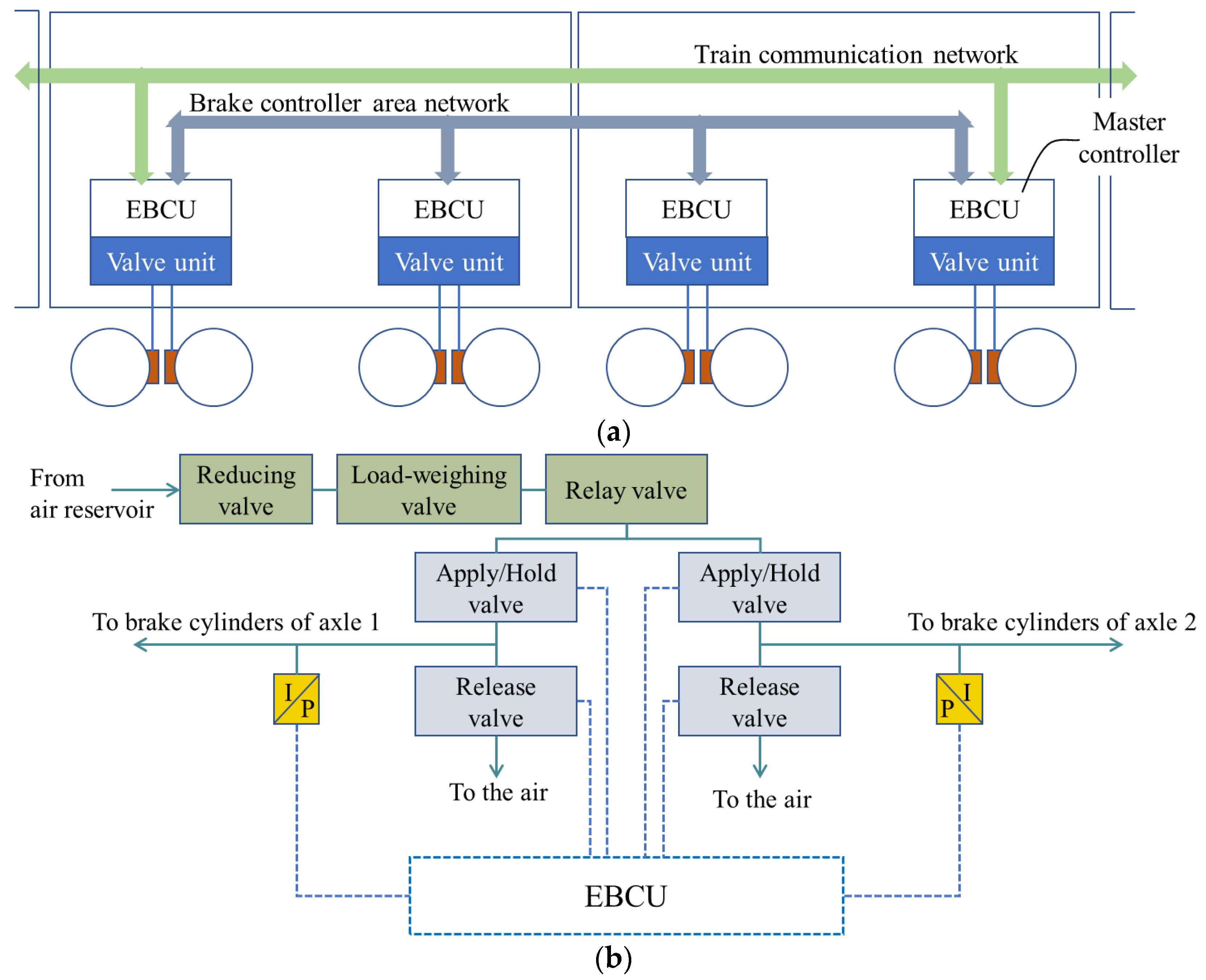
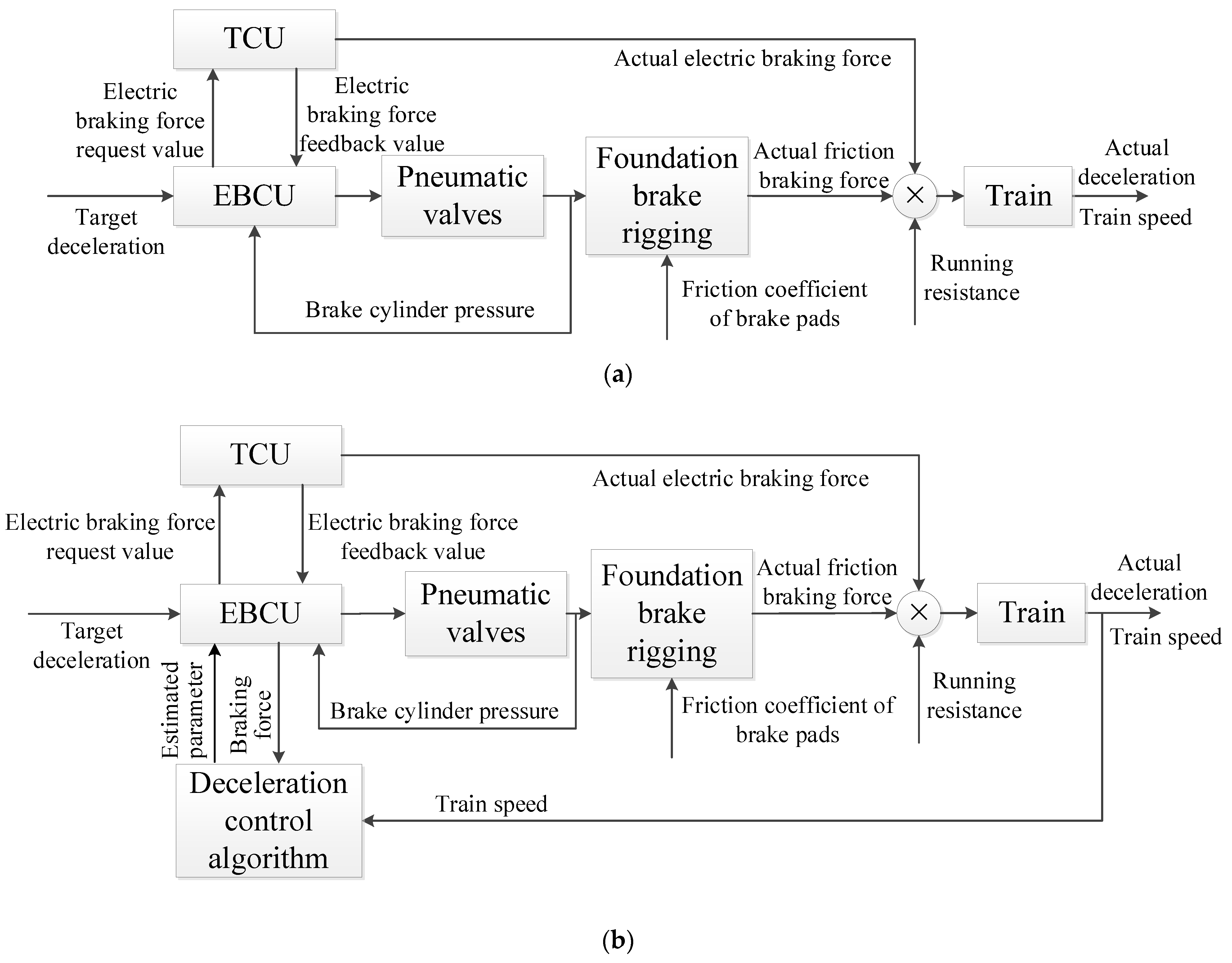
2. The Architecture and Working Principle of Braking Systems
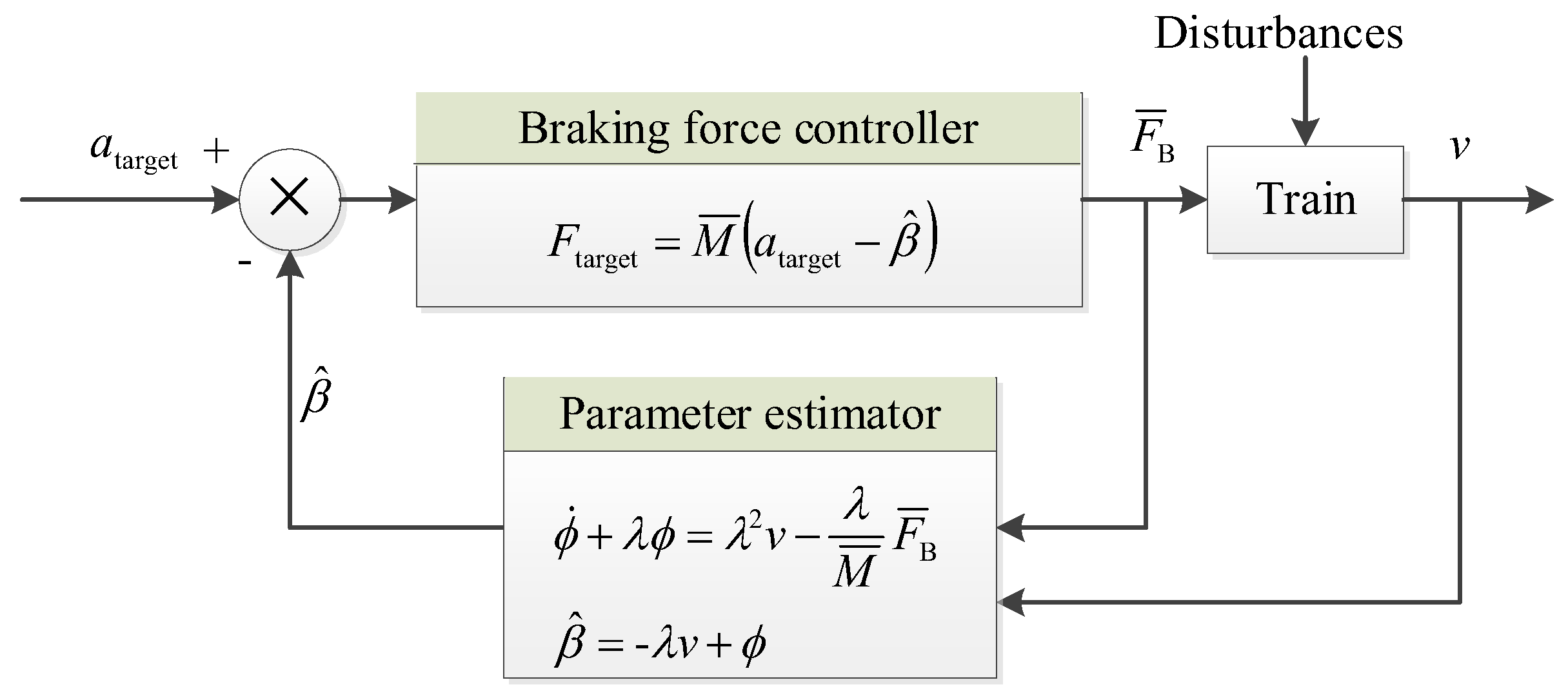
3. Deceleration Control Algorithm
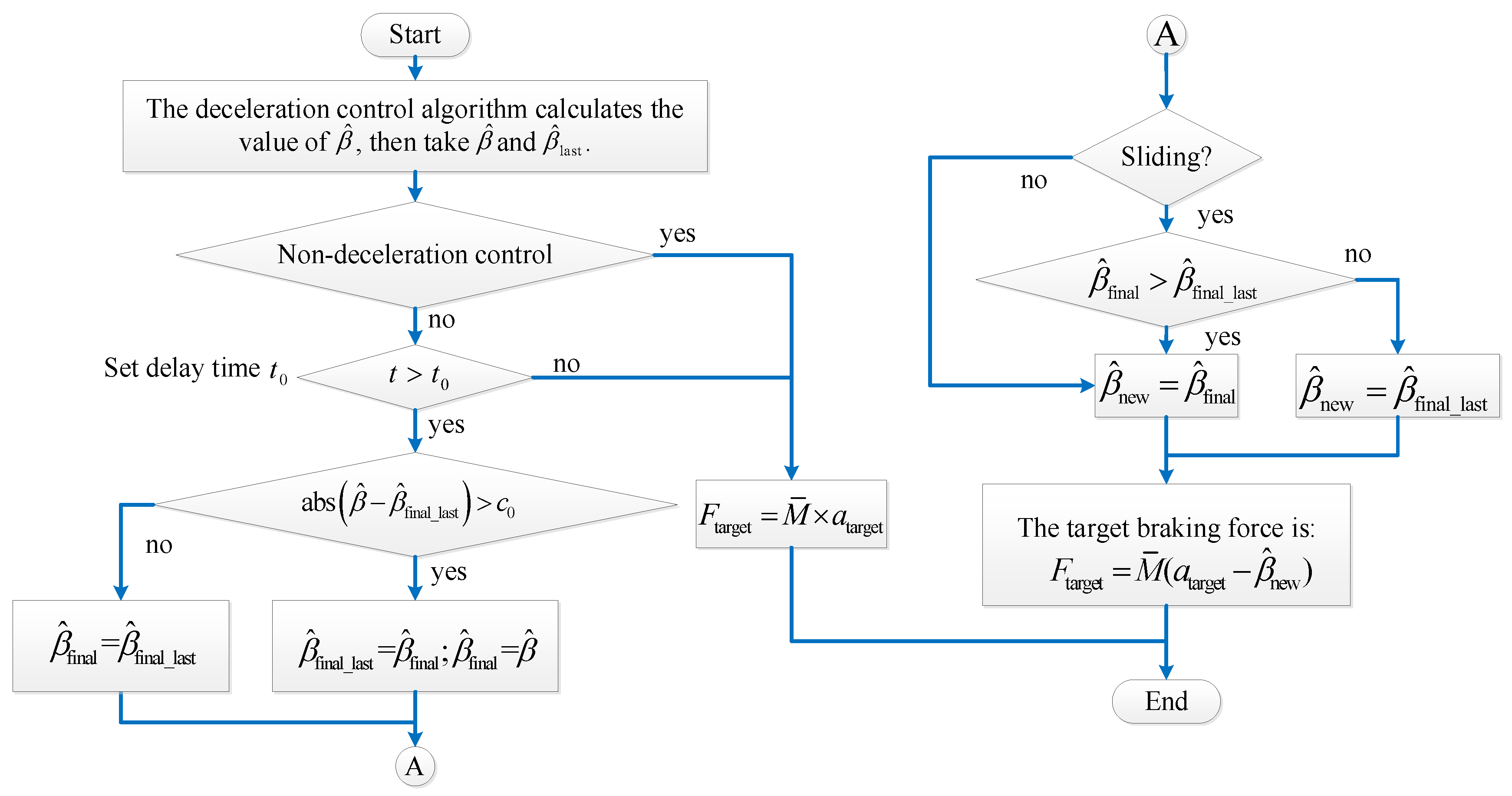
4. Software Logic Design
4.1. Target Braking Force Calculation
- (1)
- When there is no braking command, = 0;
- (2)
- Under the conditions of emergency braking and emergency traction, = 0 because those braking modes are triggered by the hardwires, and there is usually no software computing to guarantee a high safety integrity level.
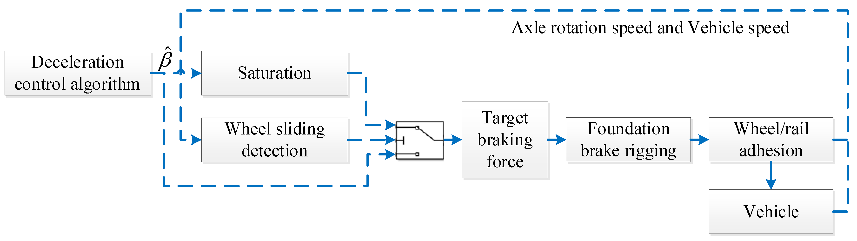
4.2. Compatible Design of Deceleration Control with Anti-Skid Control
4.3. Setting of the Delay Time
4.4. Optimization of the Dead Zone
4.5. Control Flow
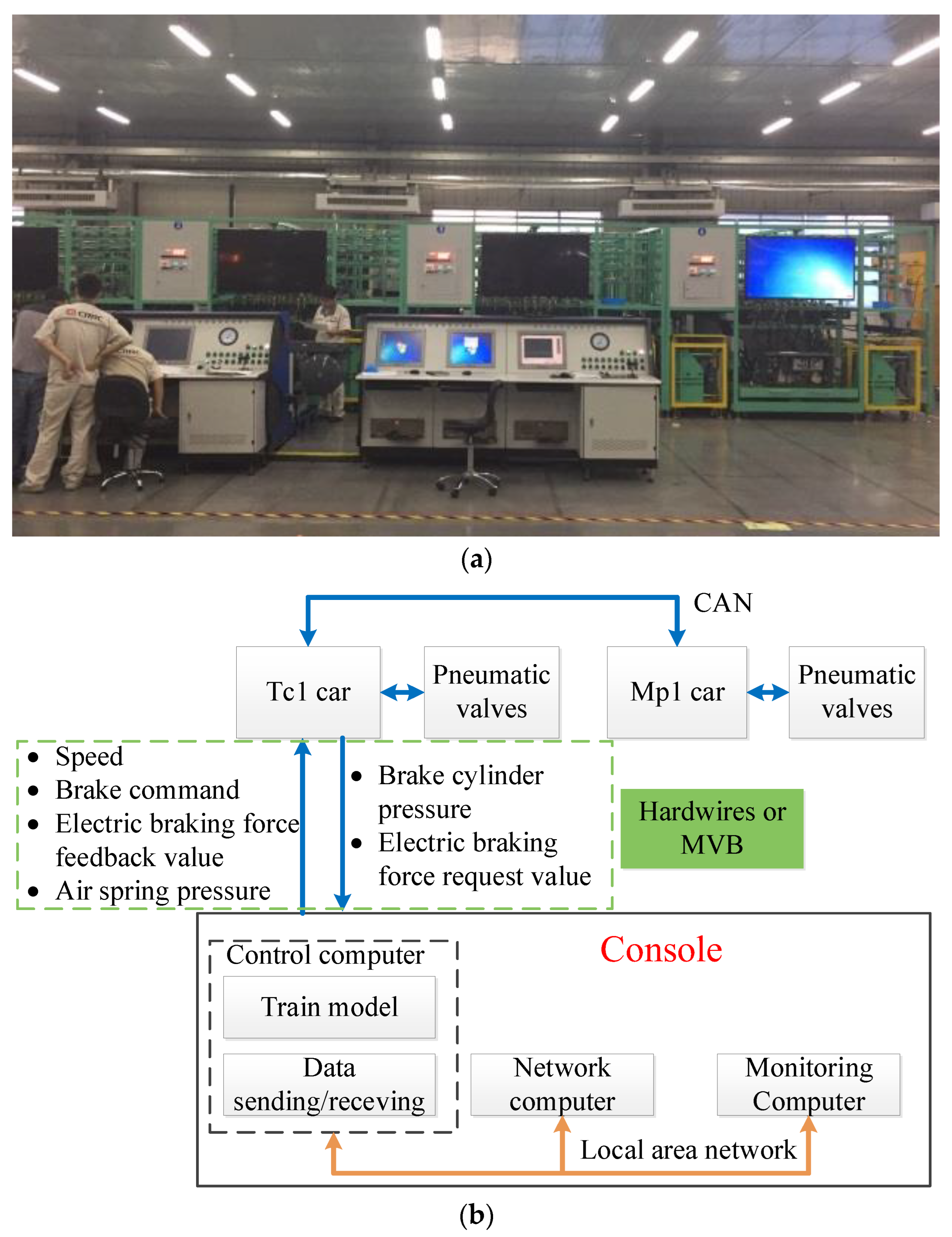
5. Test Verification with a Ground Combined Test Bench
5.1. Test Bench
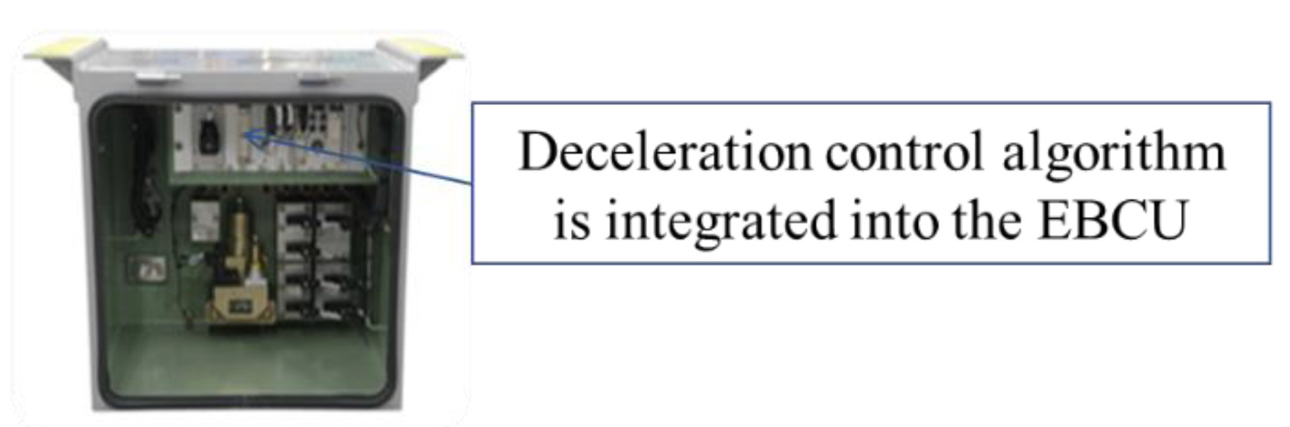
5.1.1. Hardware
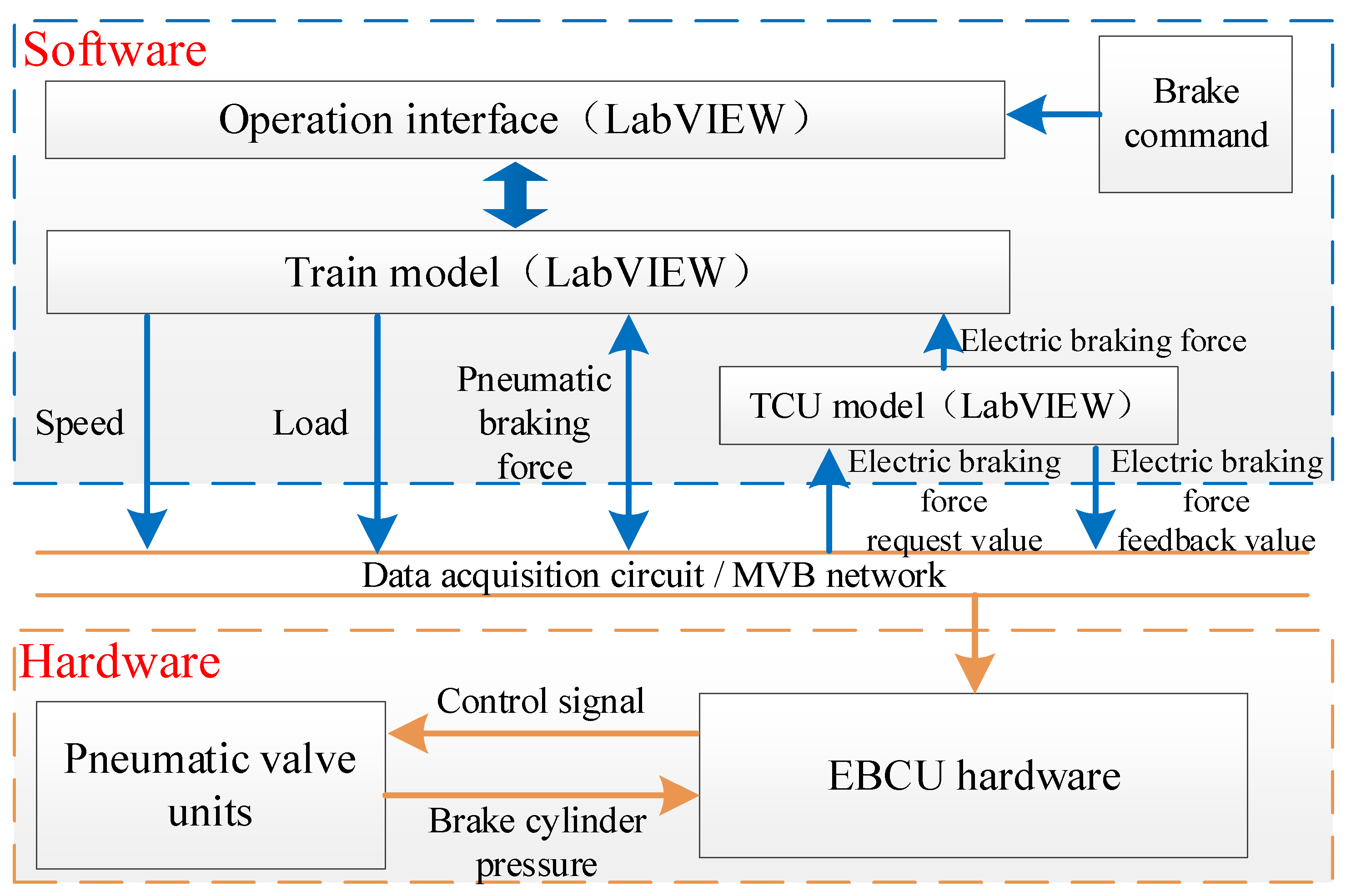
5.1.2. Software
5.2. Test Results and Discussion
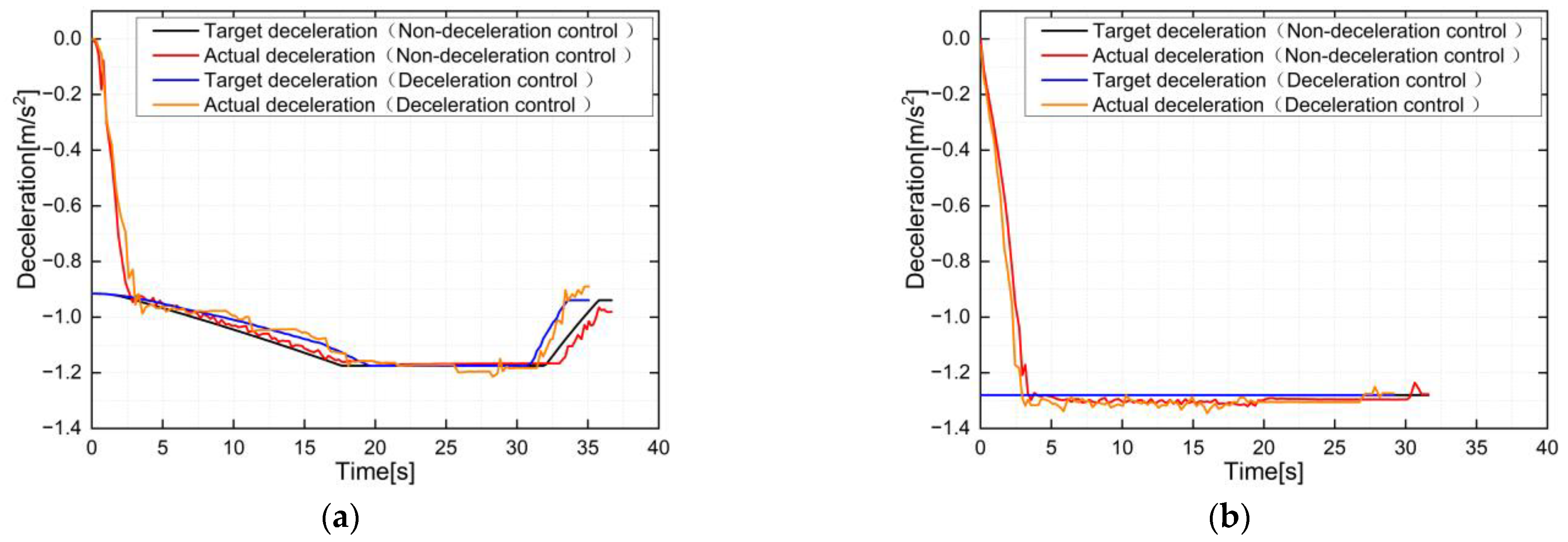
5.2.1. Test without Uncertain Parameters
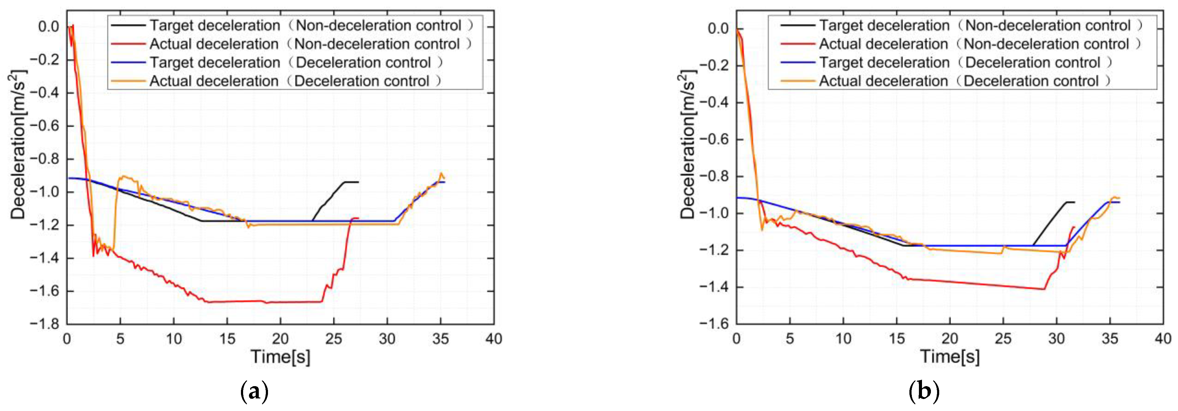
5.2.2. Test with Uncertain Parameters
- (1)
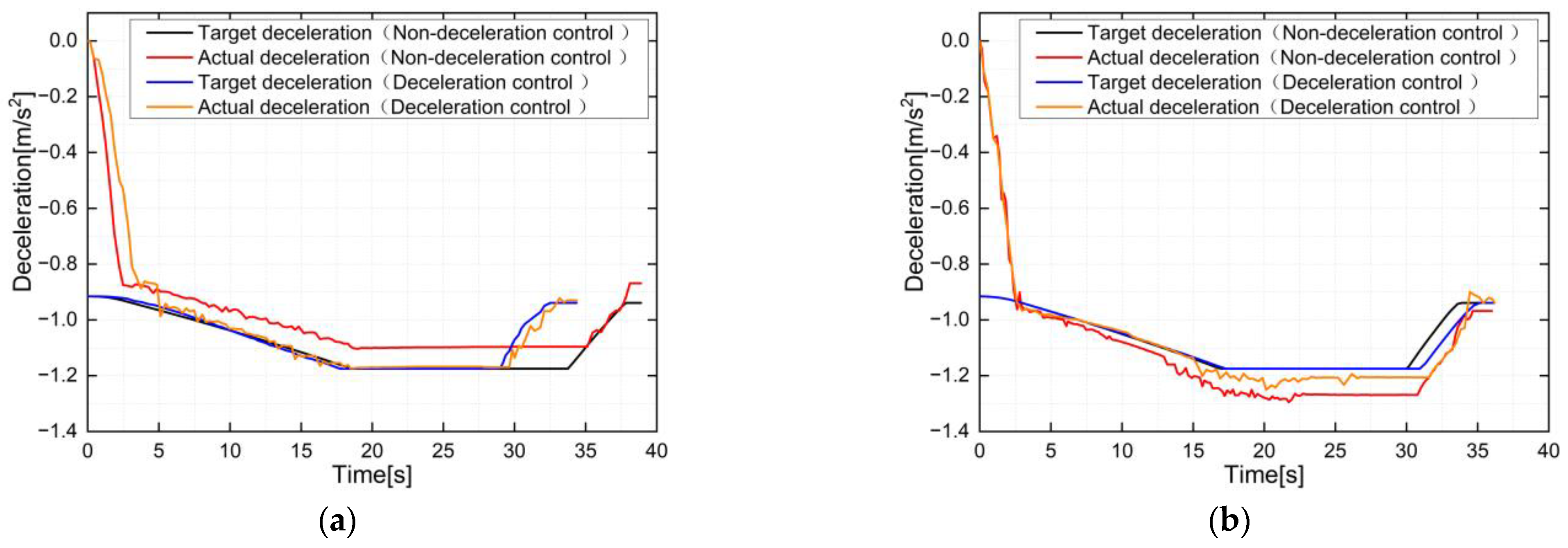
- Influence of the brake pad friction coefficient
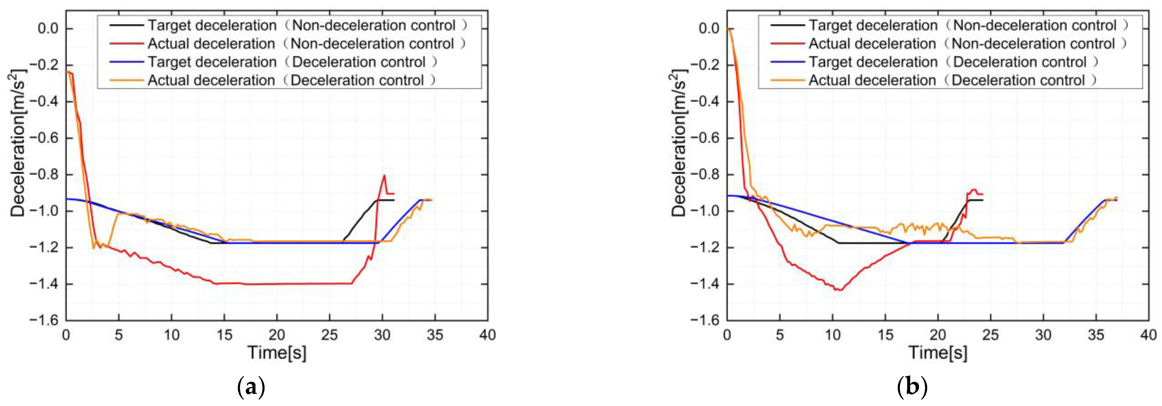
- (2)
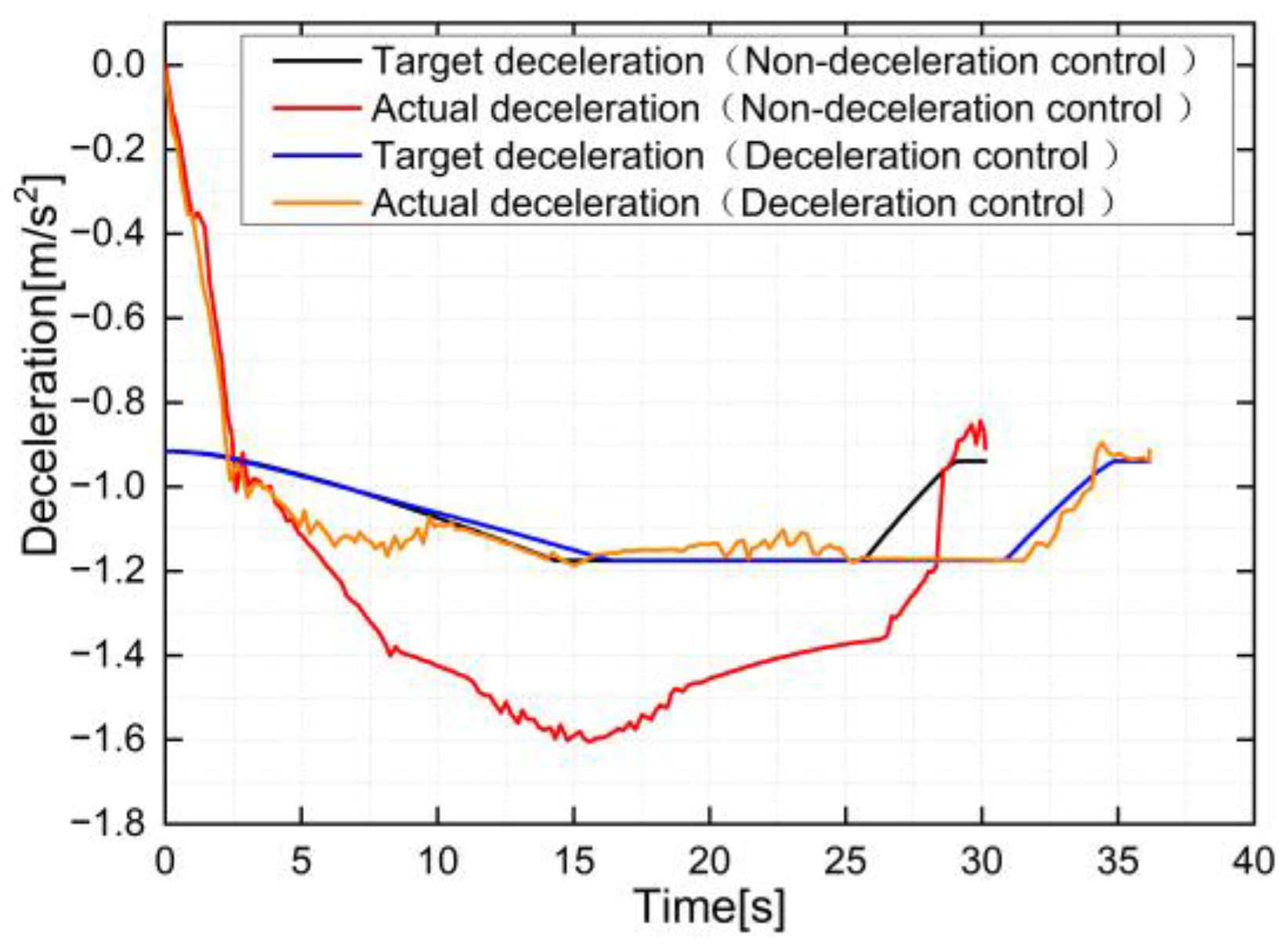
- Influence of the line ramp
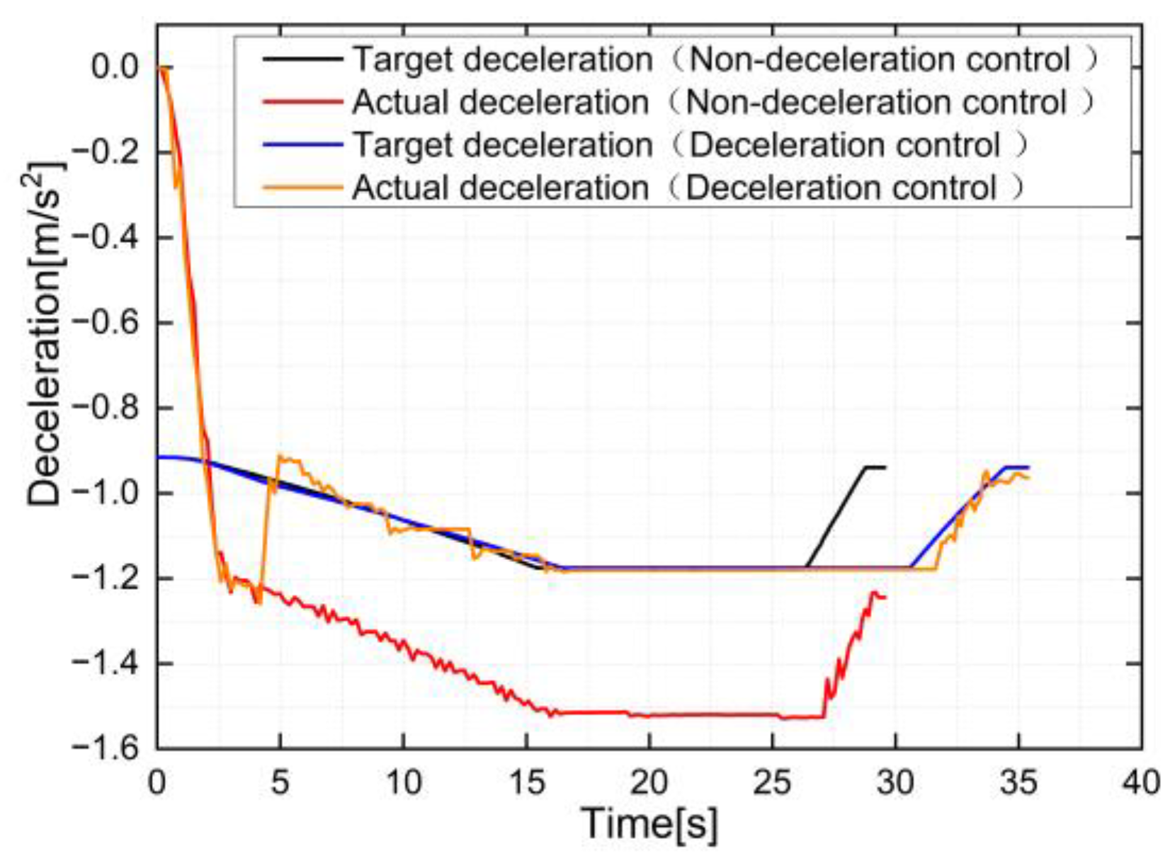
- (3)
- Influence of the vehicle load
- (4)
- Influence of the braking force feedback error
- (5)
- Influence of a combination of uncertain parameters
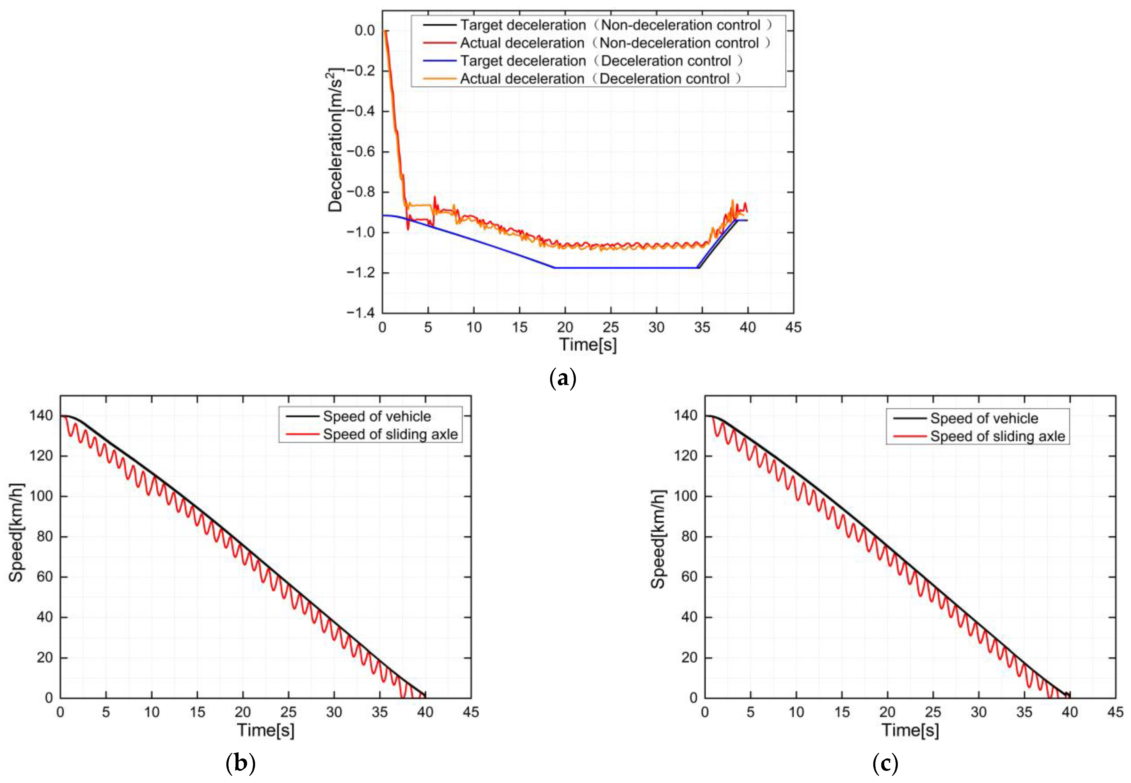
5.2.3. Anti-Skid Matching Test
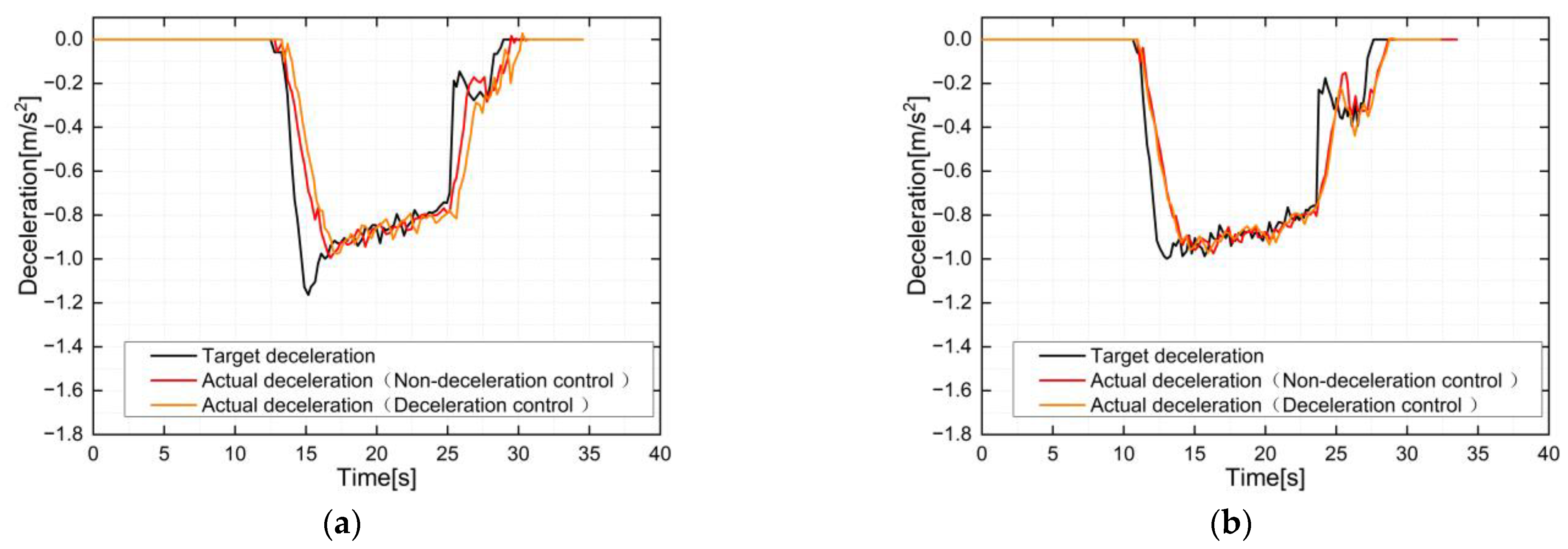
5.2.4. ATO Mode Parking Test
6. Conclusions
- (1)
- Based on the working principle of the deceleration control, an algorithm based on the parameter estimation method was derived. All the uncertain parameters can be described in a single parameter termed . The implementation of the deceleration control relies mainly on parameter estimation and the corresponding adjustment of the target braking force.
- (2)
- For engineering applications, a software logic of the deceleration control compatible with other braking control functions was designed. The estimated parameters under specific conditions, interaction with anti-skid control, delay time and dead zone were all considered in the compatible design.
- (3)
- The deceleration control mode was evidently better than the non-deceleration control mode in the presence of the brake pad friction coefficient, ramp, load, sensor errors or their combined effect. Additionally, the deceleration control function did not affect the original performance of the braking system.
- (4)
- The deceleration control method could reduce the deviation between the actual and target deceleration. The average deceleration in the deceleration control mode was relatively stable, and the instantaneous deceleration control error was smaller. However, the braking force will be frequently regulated. The maximum increment rate of the action times of the electro-pneumatic valves was 36%. Therefore, the impact on the electro-pneumatic valves should be analyzed in the future, and further optimization can be carried out to reduce the working frequency of the valves.
Author Contributions
Funding
Data Availability Statement
Acknowledgments
Conflicts of Interest
References
- Boynukalin, S.; Açikbaş, S.; Söylemez, M.T. Effect of guaranteed emergency braking rate and gradient on turnback headway time in metro lines. In Proceedings of the 2021 13th International Conference on Electrical and Electronics Engineering (ELECO), Bursa, Turkey, 25–27 November 2021; pp. 52–56. [Google Scholar]
- Thurston, D.F. Deceleration rates for safe braking distance calculations. In Proceedings of the 2017 Joint Rail Conference. American Society of Mechanical Engineers Digital Collection, Philadelphia, PA, USA, 4–7 April 2017. [Google Scholar]
- IEEE 1698-2009; IEEE Guide for the Calculation of Braking Distances for Rail Transit Vehicles. IEEE: Piscataway, NJ, USA, 2009.
- Wu, M.; Cheng, G.; Wang, X. Discussion of braking deceleration control of railway vehicle. J. China Railw. Soc. 2009, 31, 94–97. [Google Scholar]
- Wu, M.; Ma, T.; Yang, J.; Chen, M. Discussion on development trend of train braking technology. China Railw. Sci. 2019, 40, 134–144. [Google Scholar]
- Nankyo, M.; Ishihara, T.; Inooka, H. Feedback control of braking deceleration on railway vehicle. J. Dyn. Syst. Meas. Control. 2006, 128, 244–250. [Google Scholar] [CrossRef]
- Nankyo, M.; Ishisara, T.; Inooka, H. Feedback control of brake system on railway vehicle considering nonlinear property and dead time. In Proceedings of the International Mechanical Engineering Congress and Exposition, Washington, DC, USA, 15–21 November 2003; pp. 99–104. [Google Scholar]
- Nankyo, M.; Nakazawa, S.; Nanaka, T.; Yoshikawa, H. Development of a braking system equipped with deceleration feedback control. RTRI Rep. 2009, 23, 41–46. [Google Scholar]
- Nakazawa, S. Accuracy improvement of braking distance by deceleration feedback function applying to brake system. Q. Rep. RTRI 2021, 62, 167–172. [Google Scholar] [CrossRef]
- Wu, M.; Chen, C.; Tian, C.; Zhou, J. Precise train stopping algorithm based on deceleration control. In Proceedings of the 5th International Conference on Intelligent Transportation Engineering (ICITE), Beijing, China, 11–13 September 2020; IEEE: Piscataway, NJ, USA, 2020; pp. 281–284. [Google Scholar]
- Wu, M.; Luo, Z. Study on train braking deceleration feedback control based on adaptive parameter estimation. J. China Railw. Soc. 2015, 37, 8–16. [Google Scholar]
- Luo, Z.; Cao, H.; Zhang, Y.; Jiang, Y.; Wen, X.; An, Z.; Li, B. A more accurate two-level robust braking control method on high-speed EMUs. Railw. Locomot. Car 2021, 41, 169–174. [Google Scholar]
- Zhou, J.; Wu, M.; Liu, Y.; Tian, C. Train braking deceleration control based on improved smith estimator. J. Tongji Univ. 2020, 48, 1657–1667. [Google Scholar]
- Ma, T.; Wu, M.; Tian, C. Deceleration-feedback braking force closed-loop control method for urban rail train. Chin. J. Sci. Instrum. 2021, 42, 197–205. [Google Scholar]
- Zhang, M.; Xu, H. Design of urban rail vehicle brake controller based on Krasovskii functionals. J. Jilin Univ. Eng. Technol. Ed. 2015, 45, 104–111. [Google Scholar]
- Yin, J.; Chen, D.; Li, L. Intelligent train operation algorithms for subway by expert system and reinforcement learning. IEEE Trans. Intell. Transp. Syst. 2014, 15, 2561–2571. [Google Scholar] [CrossRef]
- Wang, L.; Wang, X.; Liu, G.; Xu, C. An improved predictive function control algorithm for velocity curve of urban rail vehicle. Chin. J. Sci. Instrum. 2022, 43, 273–283. [Google Scholar]
- Wang, L.; Wang, X.; Sheng, Z.; Lu, S. Model predictive controller based on online obtaining of softness factor and fusion velocity for automatic train operation. Sensors 2020, 20, 1719. [Google Scholar] [CrossRef] [PubMed] [Green Version]
- Tan, C.; Li, Y.; Yang, H. Adaptive braking control for high-speed trains with disturbances and time delays. J. East China Jiaotong Univ. 2021, 38, 64–71. [Google Scholar]
- Li, Z.; Yang, H.; Liu, M.; Liu, J. Modeling and tracking control for braking process of high speed electric multiple unit. China Railw. Sci. 2016, 37, 80–86. [Google Scholar]
- Nie, Y.; Liu, Y.; Cheng, S.; Mei, M.; Xiao, L. Unified brake service by a hierarchical controller for active deceleration control in an electric and automated vehicle. Energies 2017, 10, 2052. [Google Scholar] [CrossRef] [Green Version]
- Luo, Z.; Wu, M.; Zuo, J. Sliding mode pressure controller for an electropneumatic brake: Part II—Parameter identification and controller tests. Proc. Inst. Mech. Eng. Part I J. Syst. Control. Eng. 2018, 232, 583–591. [Google Scholar] [CrossRef]
- Luo, Z.; Wu, M.; Zuo, J. Sliding mode pressure controller for an electropneumatic brake: Part I—Plant model and controller design. Proc. Inst. Mech. Eng. Part I J. Syst. Control. Eng. 2018, 232, 572–582. [Google Scholar] [CrossRef]
- Luo, Z.; Wu, M.; Zuo, J.; Tian, C. Modelling and model validation of an electropneumatic brake on subway trains. Proc. Inst. Mech. Eng. Part F J. Rail Rapid Transit 2016, 230, 374–391. [Google Scholar] [CrossRef]
- Bu, F.; Tan, H. Pneumatic brake control for precision stopping of heavy-duty vehicles. IEEE Trans. Control. Syst. Technol. 2007, 15, 53–64. [Google Scholar] [CrossRef] [Green Version]
- Zhao, J. Braking control technology of new generation metro vehicle based on deceleration control. Mod. Urban Transit 2019, 16, 39–46. [Google Scholar]
- Kreisel, N.; Friesen, U.; Furtwängler, R.; Braeseke, J.; Ciesielski, D. Verzögerungsgeregeltes fahrzeug ermöglicht ein stabileres bremsverhalten in allen geschwindigkeiten. ZEVrail 2020, 144, 1–13. [Google Scholar]
- Sawczuk, W. Analytical model coefficient of friction (COF) of rail disc brake on the basis of multi-phase stationary tests. Eksploat. I Niezawodn. Maint. Reliab. 2017, 20, 57–67. [Google Scholar] [CrossRef]
- UIC 541-3. Brakes-Disc Brakes and Their Application-General Conditions for the Certification of Brake Pads; International Union of Railways: Paris, France, 2017. [Google Scholar]
- Lee, N.; Kang, C. The effect of a variable disc pad friction coefficient for the mechanical brake system of a railway vehicle. PLoS ONE 2015, 10, e0135459. [Google Scholar] [CrossRef] [Green Version]
- Akinsola, V. Numerical methods: Euler and Runge-Kutta. Qualitative and Computational Aspects of Dynamical Systems; IntechOpen: London, UK, 2023. [Google Scholar]
- Polach, O. Creep forces in simulations of traction vehicles running on adhesion limit. Wear 2005, 258, 992–1000. [Google Scholar] [CrossRef]


| Theoretical Deceleration (m/s2) | Running Speed of the Train | |||
|---|---|---|---|---|
| 0–5 km/h | 5–20 km/h | 20–80 km/h | 80–140 km/h | |
| Full-service braking | −0.9391 | −0.015727 × − 0.8605 | −1.175 | 0.004333 × − 1.5217 |
| Fast braking | −1.28 | |||
| Emergency braking | −1.28 | |||
| Average Deceleration | Maximum Difference of Instantaneous Deceleration 1 | |||
|---|---|---|---|---|
| Deceleration Control | Non-Deceleration Control | Deceleration Control | Non-Deceleration Control | |
| Figure 9a | −0.990911 | −0.982719 | −0.02601 | 0.042848 |
| Figure 9b | −1.133771 | −1.132026 | −0.01701 | −0.01838 |
| Results | Difference of Average Deceleration | Maximum Difference of Instantaneous Deceleration 1 | ||
|---|---|---|---|---|
| Deceleration Control | Non-Deceleration Control | Deceleration Control | Non-Deceleration Control | |
| Figure 10a | −0.02343 | 0.29539 | 0.034695 | 0.498566 |
| Figure 10b | −0.04713 | 0.05048 | 0.042405 | 0.229123 |
| Figure 11a | 0.03656 | 0.20393 | −0.02743 | 0.228948 |
| Figure 11b | −0.07623 | 0.03648 | 0.117281 | 0.264435 |
| Figure 12 | −0.0248 | 0.18829 | 0.119957 | 0.35455 |
| Figure 13a | −0.09472 | −0.13709 | 0.080415 | 0.114267 |
| Figure 13b | −0.03343 | −0.06117 | −0.02323 | −0.08865 |
| Figure 14 | −0.06408 | 0.13107 | 0.113254 | 0.385273 |
| Type of Tests | Counts of Test Groups | Action Times Under Non-Deceleration Control Mode | Action Times under Deceleration Control Mode | Rate of Change |
|---|---|---|---|---|
| Influence of brake pad friction coefficient | 48 | 2785 | 3512 | 26% |
| Influence of line ramp | 84 | 4700 | 6061 | 29% |
| Influence of vehicle load | 24 | 485 | 573 | 18% |
| Influence of electric braking force feedback error | 12 | 856 | 1168 | 36% |
| Influence of brake cylinder pressure sensor error | 24 | 1301 | 1662 | 28% |
| Influence of a combination of uncertain parameters | 12 | 683 | 929 | 36% |
| Anti-skid matching test | 84 | 11,243 | 12,371 | 10% |
| ATO mode parking test | 4 | 630 | 650 | 3% |
Disclaimer/Publisher’s Note: The statements, opinions and data contained in all publications are solely those of the individual author(s) and contributor(s) and not of MDPI and/or the editor(s). MDPI and/or the editor(s) disclaim responsibility for any injury to people or property resulting from any ideas, methods, instructions or products referred to in the content. |
© 2023 by the authors. Licensee MDPI, Basel, Switzerland. This article is an open access article distributed under the terms and conditions of the Creative Commons Attribution (CC BY) license (https://creativecommons.org/licenses/by/4.0/).
Share and Cite
Ma, T.; Tian, C.; Wu, M.; Zhou, J.; Liu, Y. A Practical Deceleration Control Method, Prototype Implementation and Test Verification for Rail Vehicles. Actuators 2023, 12, 128. https://doi.org/10.3390/act12030128
Ma T, Tian C, Wu M, Zhou J, Liu Y. A Practical Deceleration Control Method, Prototype Implementation and Test Verification for Rail Vehicles. Actuators. 2023; 12(3):128. https://doi.org/10.3390/act12030128
Chicago/Turabian StyleMa, Tianhe, Chun Tian, Mengling Wu, Jiajun Zhou, and Yinhu Liu. 2023. "A Practical Deceleration Control Method, Prototype Implementation and Test Verification for Rail Vehicles" Actuators 12, no. 3: 128. https://doi.org/10.3390/act12030128