Review

Inchworm Motors and Beyond: A Review on Cooperative Electrostatic Actuator Systems

by
Almothana Albukhari
1,2 and
Ulrich Mescheder
1,3,*
1
Mechanical and Medical Engineering Faculty, and Institute for Microsystems Technology (iMST), Furtwangen University, 78120 Furtwangen, Germany
2
Department of Microsystems Engineering (IMTEK), Faculty of Engineering, University of Freiburg, 79110 Freiburg, Germany
3
Associated to the Faculty of Engineering, University of Freiburg, 79110 Freiburg, Germany
*
Author to whom correspondence should be addressed.
Actuators 2023, 12(4), 163; https://doi.org/10.3390/act12040163
Submission received: 1 February 2023 / Revised: 30 March 2023 / Accepted: 31 March 2023 / Published: 4 April 2023
(This article belongs to the Special Issue Cooperative Microactuator Devices and Systems)

Abstract

:
Having benefited from technological developments, such as surface micromachining, high-aspect-ratio silicon micromachining and ongoing miniaturization in complementary metal–oxide–semiconductor (CMOS) technology, some electrostatic actuators became widely used in large-volume products today. However, due to reliability-related issues and inherent limitations, such as the pull-in instability and extremely small stroke and force, commercial electrostatic actuators are limited to basic implementations and the micro range, and thus cannot be employed in more intricate systems or scaled up to the macro range (mm stroke and N force). To overcome these limitations, cooperative electrostatic actuator systems have been researched by many groups in recent years. After defining the scope and three different levels of cooperation, this review provides an overview of examples of weak, medium and advanced cooperative architectures. As a specific class, hybrid cooperative architectures are presented, in which besides electrostatic actuation, another actuation principle is used. Inchworm motors—belonging to the advanced cooperative architectures—can provide, in principle, the link from the micro to the macro range. As a result of this outstanding potential, they are reviewed and analyzed here in more detail. However, despite promising research concepts and results, commercial applications are still missing. The acceptance of piezoelectric materials in some industrial CMOS facilities might now open the gate towards hybrid cooperative microactuators realized in high volumes in CMOS technology.

1. Introduction

Electrostatic actuation is an actuation principle that is widely used in billions of commercial devices and products today, e.g., the actuation of the so-called primary excitation in MEMS (microelectromechanical systems) angular rate sensors (gyros), which are based on the Coriolis effect, is provided in most commercial devices electrostatically [1,2]. The successful emergence of electrostatic actuators is based on several key factors: the actuation principle does not rely on specific materials, and thus, electrostatic actuators can be realized with standard CMOS-processes, while taking full advantage of the technological advancement therein, such as the ongoing miniaturization and creation of high-aspect-ratio (HAR) microstructures, e.g., by using deep reactive-ion etching (DRIE) [3]. The feasibility of electrostatic actuators also benefited from the development of the so-called surface micromachining [4].
Additionally, the basic actuation cell is a simple capacitor, usually with one electrode fixed and the other electrode anchored via a tethered suspension to the substrate. The energy density of an electrostatic actuator and the corresponding forces can be simply derived from the change of energy stored in that capacitance. For a parallel-plate arrangement, the stored energy W in the capacitance C is given by Equation (1), where U is the voltage potential applied across the electrodes, ε r and ε o are the relative and vacuum permittivities, respectively, d is the distance between the electrodes, and a and b are the overlapping dimensions of the capacitor’s electrodes. The acting forces can be calculated by the corresponding derivatives in respect to distance and actual overlap.
W = 1 2 C U 2 = 1 2 ε r ε o U 2 a b d
However, the so-called z-movement capability (change of d ) is very limited due to decreasing forces for larger distances d (∝1/ d 2), and due to the pull-in effect for small distances. Furthermore, without considering special effects, e.g., provided by fringe fields, electrostatic actuation is unidirectional, i.e., the forces in respect to Equation (1) are always directed to maximize the electrostatic energy stored in the capacitance. In the case of a comb-drive-like setup, this means that the force is directed to achieve a complete overlap of opposing “fingers” of the interlaced combs. Therefore, upon electrostatic actuation, a counter force starts building up in the mechanical suspensions of the movable or deformable electrode, which will drive the movable part back to the starting position once the potential between the electrodes is switched off. Based on Hooke’s law, these restoring forces are linearly increasing with the deflection of the suspending beams. Thus, the restoring actuation forces are depending on the beam geometry and material properties (Young’s modulus), and therefore are fixed for a given design. As discussed in several examples in Section 3, an important feature of cooperation is to achieve bidirectional operation, where the movement back to the starting position can be actively controlled.
Further advantages of electrostatic actuation are high energy transfer efficiency (low power consumption), fast response time and high resonance frequencies of most miniaturized spring-mass systems, allowing a fast dynamic operation [5]. Additionally, the electrostatic effect shows low temperature dependence and allows high operation temperatures when using suitable materials such as poly-Si and metals.
An early implementation of electrostatic actuation was the force feedback loop and self-test function integrated in the 1990s in the MEMS accelerometer ADXL50 from Analog Devices [6]. In consumer electronics, an example is projectors that are realized by the so-called digital micromirror device (DMD) from Texas Instruments (TI), which can be even integrated into smart phones such as Samsung’s I8530 Galaxy Beam [7].
Different to most other actuation principles, miniaturization increases the performance of electrostatic actuation by virtue of the scaling [8] and Paschen’s laws [9], whereby the former allows efficient actuation with relatively large force and energy density on the microscale (in respect to dimensions of electrodes and distance between them), and the latter provides larger breakdown voltages, which allows greater electric field strengths, in smaller gaps between electrodes.
However, electrostatic actuation also has certain limitations and drawbacks, such as low (absolute) force (typically µN), small stroke (typically µm), inclination to stiction, vulnerability to dielectric charging and—based on a planar design architecture and resulting mostly uniaxial movements—limited aptitude for “3D-operation” and more complex actuation tasks and movements, such as motors.
To overcome the inherent displacement limitation of electrostatic actuation, over the past few decades, many researchers have proposed various mechanisms that accumulate the repeated, short actuation steps of an electrostatic actuator into much longer displacements. Such mechanisms are typically called motors, which are in principle capable of indefinite motion, at least in one degree of freedom. For this purpose, some new motor concepts specifically suited for electrostatic actuation have been proposed, e.g., the so-called scratch drive actuator (SDA) [10], as well as other, already known concepts, such as the inchworm motor, have been adapted to electrostatic actuation [11]. Typically, these electrostatically driven motors make use of cooperation between different actuators and/or structures within the system.
In this review, we first provide definitions for cooperative electrostatic actuators and for different levels of cooperation. We will then present examples of cooperative electrostatic actuation principles and systems for each cooperation level. As a specific class, hybrid cooperative systems are presented, where electrostatic actuators are cooperating with actuators using other actuation principles. After a discussion, where we compare different cooperative architectures, we conclude the findings and try to present an outlook for future developments in this field. Being part of the Special Issue on “Cooperative Microactuator Devices and Systems”, this review focusses on electrostatic cooperative actuation systems. Other principles will be considered in other contributions in that Special Issue.

2. Methodical Approach: Definition of Cooperative Electrostatic Microactuators

So far, no generally accepted definition or classification of cooperative microactuators is available. This holds especially true for cooperative actuator systems using electrostatic actuation as their base. In this review paper, cooperative electrostatic microactuator systems are defined by the following conditions or properties:
  • Different actuators—at least one using electrostatic actuation—are integrated to form a cooperative, synergistically operating system, which generates new functionalities, and thus can also fulfill complex tasks that are impossible to achieve by the individual actuators found within the system (e.g., a larger force, a longer stroke, or a complex travel path).
  • The scale of functional structures in these actuators is in the order of µm.
  • The actuators are placed in a closely spaced arrangement to allow interaction between them and provide synergy of the individual microactuators and integration on a single chip, e.g., monolithic integration.
We distinguish “pure” electrostatic cooperative microactuator systems, i.e., those made up exclusively of electrostatic microactuators, from hybrid cooperative microactuator systems, in which, in addition to electrostatic actuation, other actuation principles or effects are used, e.g., to accomplish bistability or even multistability.
To structure this review paper, we are proposing, within the given definition, a classification based on system architecture and degree of cooperation. Three levels of cooperation are defined and presented:
  • systems, where the cooperation is derived by the integration of independent, not coupled actuators through the electronic control system;
  • a very limited number of cooperating actuators (2–4), where the cooperation is based on simple mechanical coupling structures of these actuators.
  • some actuators (2–5) with strong interaction using smart mechanical coupling (e.g., coupling activated by actuation itself) to allow, e.g., complex 3D-trajectories;
  • architectures which are already providing by cooperation the base for integration in even more complex cooperative actuation systems.
  • Advanced/strongly cooperative architectures (Section 3.3):
  • cooperative sub-architectures are integrated and combined into complex systems;
  • huge numbers of coupled actuators integrated into a functional system.
This structure can also be viewed as somewhat indicative of the chronological order, given that early and even commercialized examples of weakly cooperative electrostatic actuator systems were introduced in the 1990s, whereas strongly cooperative systems are still a topic of fundamental research.
In a further section, Section 3.4, we present concepts, where electrostatic actuators are combined with other actuation principles. This section is called ‘Hybrid System Architectures’.
An early example of a cooperative microactuator system with weak cooperation between the actuators is the DMD [12]. Here, a typical system features more than a million independent mirrors that are working in parallel to cooperatively create an image. The cooperative image creation is provided by the control logic, which individually addresses each single micromirror (pixel) without any coupling of the independent micromirrors. An example of medium cooperative architecture is xyz-stages, which allow out-of-plane movement even with a planar structural design, by using specific hinges. Finally, cooperative microactuator systems with advanced cooperation between distributed actuators are, e.g., electrostatic inchworm motors, whereby different actuators are working cooperatively to create a single step in a long sequence of a step-like motion, thus allowing very large travel ranges (several mm instead of µm) and, by combining many driving units in a cascaded system, also large forces (mN instead of µN). The quality of such cooperative electrostatic microactuators is therefore called, in this review, “strong”, because the successful functioning of such systems needs not only addressability of each actuator within the system, but also coordinated action of the different coupled actuators, since they depend on each other. Additionally, such devices are able to carry loads or create relatively large forces and provide larger travel ranges.
Electrostatically driven microactuators using direct cooperation between the actuators, or cooperation at a system level, are described in several research papers. However, compared to the field of electrostatic actuation in general, the number of research papers is rather limited, and for the most part, even the papers listed in this review are not focusing on “cooperation” or cooperative aspects specifically, and do not pronounce the cooperative or coupling character of the described actuator systems. For this reason, a systematic search of related publications by keywords is difficult, and the search results provided are unreliable. For instance, a search on Google Scholar combining the single words and the full phrase “cooperative electrostatic actuation” provides only 10 results, most of them fulfilling the given definition. However, combining the keywords actuator, electrostatic and cooperative with the phrase “cooperative electrostatic”, gives 74 results in Google Scholar, from which only 11 are relevant in respect to the given definition (and even not providing the papers presented in this review!). On the other hand, a general search with the keywords “electrostatic”, “microactuators” and “cooperative” provides 1720 results, but many of them are not relevant in respect to the given definition of cooperation.
Similar results are found for a search on science direct: When using the three keywords “electrostatic”, “actuator” and “cooperative”, 1198 results are provided. However, only 104 results are found, when using the keywords “electrostatic”, “microactuators” and “cooperative”. These results are almost uniformly spread over the last 20 years. In contrast, an advanced search combining those three keywords in the text with the criteria that these are also used in the title or abstract fields provides only one result. By reducing the keywords needed to be found in either of those fields to “electrostatic” and “actuator”, 22 search results are found.
Therefore, a simple keyword-based search on “cooperative microactuators” is not reliable. Instead, we analyzed papers dealing with miniaturized electrostatic actuators in general, but with some special features, for example, in respect to motion (e.g., feasibility to provide not only unidirectional movement), stroke (>>µm) and force (>>µN). For this review, about 140 papers were identified according to the above definition of cooperative electrostatic actuation systems. From these, 82 are presented in more detail or referenced in this review. The selected papers are representing basic principles and concepts of cooperation.
Whenever possible, we try to introduce, as examples of a given cooperation category or method, those publications where that specific idea was first presented before referencing more recent papers.

3. Design Principles and Architectures of Cooperative Electrostatic Microactuators

3.1. Weakly Cooperative Architectures

As we established in the aforementioned classification, this Section reviews actuator systems that exhibit a form of cooperation, but on a weak level, from one perspective or another. Examples of such systems are those that have actuators with little to no coupling or physical dependence among them, such as the independent optical actuators that collectively create an image or drive a multi-channel switch. Additionally, systems that consist of only few actuators and that have only simple and passive coupling elements, and those that cascade identical actuators to increase their displacement range or force, will also be reviewed in this section.

3.1.1. Cooperation by Control Logic

As already mentioned, a well-known example of this kind is the DMD [12], in which more than a million mirrors can be individually actuated and work in parallel to cooperatively create an image. The cooperative image creation is provided by the control logic, which individually addresses each single micromirror (pixel) and drive it to assume one of two states: on or off. Thus, the cooperative quality is similar to a microelectronic device, such as static or dynamic random-access memory (SRAM or DRAM) chips, where millions to even billions of basic unit cells (typically consisting of six transistors) are controlled for particular functions. In that respect, we call the quality of cooperation of such types of cooperative microactuator systems “weak”.
Another early example belonging to this type of cooperative actuation systems was presented by Liu et al. [13]. In this solution, an array of mirrors is arranged vertically by micro latches on micro platforms that can be tilted electrostatically. Hence, upon selective excitation, the micro platforms are pivoted to bring their respective mirrors into the paths of light beams. In this way, a 4 × 4 optical switch is realized. The arrangement of the 16 mirror platforms can be seen in Figure 1. An exceptional feature of the surface micromachined device is the pronounced out-of-plane movement, which is created by means of electrostatic actuation in combination with suitable pivoting joints for the tilting plates on the substrate (draw-bridge beams). In the absence of a driving voltage, the tilting plate is in the up-position, and it moves downwards by applying a voltage between the plate and an electrode on the substrate beneath it. In 2002, a similar solution for a 16 × 16 switch was presented by the American company OMM Inc. (San Diego, CA, USA) [14].
These examples belong to the group of quasi loadless actuators as the actuation only has to overcome the restoring counterforce provided by the suspensions of the movable or deformable structures. This is typically the case for microactuator systems used for optical applications, e.g., optical switching. A review about optical switches, which are mostly electrostatically actuated, and not entirely using cooperative architectures, is provided in [15].

3.1.2. Cooperation through Passive Mechanical Coupling Structures

Other actuation systems with weak cooperation are those, where the cooperation of few actuators (2–4) is provided by mechanical coupling structures, which are passive and simple, in most cases spring-like structures or freestanding stiff beams. One purpose for such cooperation is to achieve an actively controlled movement of the actuators back to the non-powered state position by electrostatic actuation, rather than being passively moved back by the elastic counterforce built up in the actuators’ beam suspensions, thus, as a consequence, not being entirely dependent on the beam geometry and materials’ properties. Another purpose is to extend uniaxial linear actuators to planar movements, i.e., two-degree-of-freedom movements (2-DoF).
A bidirectional mode within a 2-DoF actuation system was presented in [16,17], where two groups of opposing comb drives are cooperatively acting together (one for the x-direction and one for the y-direction) to move a xy-stage, to serve, e.g., as a scanning unit for an integrated atomic force microscope (AFM). A schematic of that set-up is shown in Figure 2. The cooperation between each of the two opposing comb drives is provided by the long freestanding beams connecting the opposing comb drives. These beams are stiff in the direction of the intended electrostatic actuation and allow a (soft) bending in the perpendicular direction. Thus, the length of the beam together with specific stabilizing structures for the movable parts of the comb drives allow a reasonable decoupling of the x and y movements, e.g., 35 dB for a beam length, width and thickness of 600 µm, 2 µm and 4 µm, respectively. Several comb structures are placed in parallel, similar to a muscle fibril (sarcomere). Therefore, the authors in [16] called this design, which reduces the driving voltage, sarcomere actuator.
Recently, a similar sarcomere design was presented as a three-dimensional (3D) polymer interdigitated pillar electrostatic (PIPE) actuator for large forces [18]. With a 3D printed array of parallel as well as stacked comb drives the authors claimed to achieve a work density close to that of a human muscle and a force of around 100 N at 4000 V.
The simple approach of cooperation by connecting beams for bidirectional electrostatic actuation is a quite often used design, e.g., a similar actuation principle was employed in [19]; however, it was combined with self-sensing for accurate nanopositioning.
Furthermore, more sophisticated examples of this type of mechanical coupling of structures will be discussed in Section 3.2.

3.1.3. Cascaded Systems

An early concept of a cascaded system was presented by Minami et al. [20]. The basic driving unit, the so-called distributed electrostatic microactuator (DEMA), consists of two long wave-like insulated electrodes. Due to the wave-form of the electrodes, a large electrostatic force at those locations with a small gap is obtained, which deforms the wave-like structure easily at locations with a wider gap and therefore also provides a large deformation of the driving unit as a whole. By connecting many driving units in series (long DEMA), the total deformation is increased; on the other hand, by connecting many of the wave-formed electrode pairs in parallel, a force amplification is obtained (see Figure 3a). For a miniaturized DEMA, a displacement of 28 µm at 160 V was measured and a force of 6.3 µN at 200 V was simulated by the finite element method (FEM) [20].
Another cascaded electrostatic actuation system was proposed by Chiou et al. [21] to overcome the side stability limitation (side pull-in) and extend the stable traveling range of comb-drive actuators by a serially cascaded multi-stage configuration. The three-stage cascaded system architecture is achieved by a connection frame. The first stage is fixed, whereas the second and third stages are movable. Within each stage, one part of the comb drive is fixed, while the other one is movable and can follow the frame deformation. The connection frame was made out of 455 nm thick poly-Si. For the comb structures, a four-metal-layer process with tungsten as vias/contacts was used, thus providing a capacitance height of around 6 µm. The total stroke of the cascaded actuator system is the sum of strokes of the first, second and third stages. Therefore, with the 3× cascaded system shown in Figure 3b, the stable traveling range was extended by 200% compared to a single actuator. However, the side pull-in instability of the cascaded system, relative to its size, is the same as that of a single stage. A total displacement of 10.1 µm was reported at 125 V. However, due to residual stress in the layers, the movable structures showed a slight out-of-plane bending which caused an unbalance between the stroke contributions of the 3 stages. Such cascaded comb drives are often combined with bidirectional electrostatic actuators using opposing comb drives, as the one shown in Figure 2.
Recently, a serially cascaded system with three gap-closing parallel-plate actuators was presented by Schmitt et al. [22,23]. The single actuators are linked by connecting beams. The specific step-like movement of the total system is obtained by a special design of the electrode gaps, which are increasing from the first to the third actuator in the row, and a defined sequence of powering the actuators with the smallest-gap actuator first, such that the gaps of subsequent actuators are decreasing when preceding actuators are activated. In this way a successive pull-in of the actuators in the row is achieved. Guiding sinusoidal-shaped springs guarantee a pure translational movement. The system also allows a bidirectional movement and strokes of up to 35 µm at 50 V, with intermediate steps of 6.9 and 19.4 µm.
Another interesting cascaded design approach was presented in 2015 by Conrad et al. [24]. The basic actuation cell is an electrostatically actuated leverage structure, many of which are placed periodically on a bendable cantilever; thus, we assign this concept under cascaded systems. In this novel approach, the so-called nano electrostatic drive (NED), the actuation by electrostatic forces is combined with a bimorph leverage mechanism to achieve an actuation distance larger than the gap separation between electrodes. The actuator cell has top and bottom electrodes separated by a submicron gap. The asymmetrical compliance of these two mechanical elements, combined with a certain non-planar topography of the gap and electrodes, make up a robust mechanical leverage system capable of producing controllable, repeatable, out-of-plane deflections. Moreover, so-called V- or Λ-shaped electrodes will result in a cantilever bending in the upward or downward direction, respectively. It was demonstrated that a non-optimized cantilever design having a total length of 4 mm and V-shaped actuator cells with a gap of 200 nm achieved a total deflection of 272 nm (136% of the gap) at a driving voltage of 45 V. The authors simulated tens to hundreds of micrometers of beam deflection for a cantilever beam length of 2 mm. The high potential of this novel cooperative system will become more evident when a recent, more elaborate inchworm motor system based on the NED actuator is discussed in Section 3.3.

3.2. Medium Cooperative Architectures

Following the classification presented in Section 2, medium cooperative architectures are characterized by specific and sophisticated coupling, or active joints between actuators, e.g., for achieving controlled movements with complex 3D trajectories. Additionally, cooperative actuator systems and principles providing bistability and stepping mode are presented here.

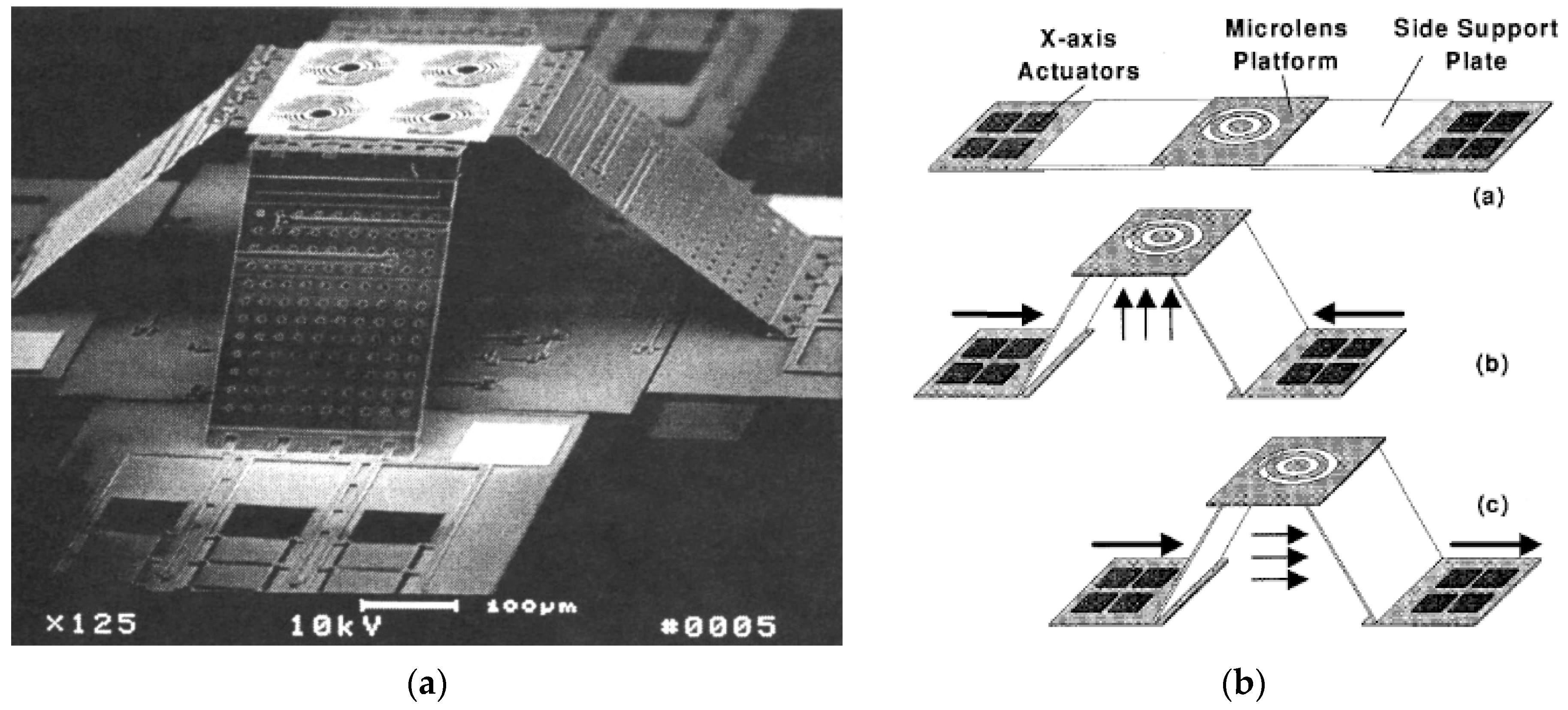
3.2.1. XYZ Stages and Multi-DoF Systems

A challenging design aspect for xyz-stages in particular, and for multi-degree-of-freedom (multi-DoF) movements in general, is the inherent mechanical coupling across the different movement directions. This is usually addressed by specially designed flexure structures that guide the deflection caused by a certain actuator along its corresponding axis, while limiting its influence in other directions, such that efficient, controllable actuation with a tolerable level of cross-coupling is achieved. Additionally, in different applications, also different degrees of coupling between the actuators are allowed or needed; thus, different approaches of coupling/decoupling the motion into the different directions are discussed in this section.
A very early example of an actuation system with such smart mechanical coupling of the actuators is the xyz-stage presented in [25], which is shown in Figure 4. The basic actuation units are defined by four groups of electrostatic SDAs, an actuation unit that in itself represents a cooperative subsystem, as we will show in Section 3.2.3. Here, each group consists of nine SDAs that are integrated in an actuator plate. The four plates are cooperating to control the position of a central stage, on which four micro-Fresnel lenses have been integrated, through special mechanical couplings that link together each pair of plates that are opposite to one another. The xyz-movement of the central stage is created by appropriate actuations of the opposing plate actuators. To achieve the required xyz-movement, the system needs, in addition to the four in-plane suspended actuator plates, special hinges (so-called polarity hinges) as well as supports (sliding joints) to create the large out-of-plane motion, e.g., an upward movement (case (b) in Figure 4b) is obtained, when the two opposing plates are actuated in opposite directions, and as a result, a critical force is produced at the hinges, which results in a redirection of the planar forces into the z-axis. Once the stage is in the up-position, it can be moved in the x or y directions by an equal actuation of the corresponding pair of opposing plates into the same direction (case (c) in Figure 4b). Therefore, the z-movement as well as the xy-movement are the result of cooperation of the (planar) actuators. A lateral movement up to 120 µm and a vertical movement even up to 250 µm with a resolution of 27 nm was reported with the shown setup.
In spite of the title, the “hybrid electrostatic microactuator” presented in [26] is a pure electrostatic system combining vertical comb driving (VCD) and parallel-plate driving (PPD) to realize xyz-movements. The VCD and PPD work together to pull the moving parts of the actuator downwards from an elevated position, which is a result of internal stress in the used structural layer (Ni). The main advantage of the approach presented by Hailu et al. in [26] is that the design can be realized with only one structural layer for both, the VCD and PPD. Even though the VCD and PPD are driven by the same voltage, we count the approach among medium cooperative architectures since the movements of the cooperating actuators are very different, and the system function is relying also on a suitable mechanical stress in the structural layer and special, so-called curve-up beams, which are deformed by the VCD and PPD. For that, the VCD and PPD movements are coupled to the curve-up beams through appropriately designed serpentine springs.
Another approach for realizing a xyz-stage was proposed by Ando [27], where a xyz-movement is obtained by three stages, which are all driven by independent comb-drive actuators and connected by suspensions, some of which are purposefully designed as tilted leaf springs. The out-of-plane movement is a result of the tilt angle of the leaf springs relative to the substrate. To achieve a certain position in the working space, a cooperative action of the three stages (i.e., certain combination of the corresponding electrostatic forces) is required, where the proper relation between the forces depends on the tilt angle of the leaf springs. However, even though most parts of the xyz-stage were fabricated by Silicon-On-Insulator (SOI) technology and surface micromachining, the most critical and important structure for the out-of-plane movement, the tilted leaf springs, was fabricated by focus ion beam scanning electron microscopy (FIB-SEM), which is not suitable for upscaling the fabrication. The stroke is also very limited (1.0 µm for x, 0.13 µm for y, and 0.4 µm for z at 100 V). Additionally, due to the strong coupling of the three movements, an independent control of the x, y and z positions is not possible.
Therefore, to achieve arbitrarily controllable xyz-movements, mechanically less coupled stages can be advantageous. Such a design was presented by Liu et al. [28], where two opposing groups of coupled comb-drive actuators provide the xy-movement and a parallel-plate actuator causes the independent vertical actuation, which is decoupled by long tethering beams. By this straightforward design, movements of about ±12.5 µm at an applied actuation voltage of 30 V in the x and y directions and 3.5 µm at 14.8 V in the z direction were achieved, with a cross-axis coupling of less than 0.3 µm.
Another approach with a direct actuation for the z-movement by a dedicated comb-drive actuator in a 3-DoF micromanipulator with gripping function was presented in [29]. The structures were etched by DRIE in a high-aspect-ratio micromachining (HARM) process, where two DRIE steps were employed to etch trenches of two different depths, especially needed for the z-movement (staggered electrodes to provide electrostatic attraction in the z-direction). The stages are connected by two sets of linear springs allowing movements in the x and y directions and a torsional spring for the z-movement. However, the strokes of the micromanipulator in the xy-plane were only around 1 µm (at 20 V), while the out-of-plane displacement was characterized by an angle of 0.043° at 50 V. The total displacement of the gripper was 5.93 µm at 50 V.
The design of a decoupled dual-axis actuation MEMS microgripper is presented in [30]. By allowing a controlled and independent xy-movement of a so-called actuation arm relative to a sensing arm, which is equipped with electrostatic sensing combs, a gripping mode and a sensing mode are obtained. Therefore, we assign this design to a multi-DoF system. Here, two perpendicularly aligned planar comb-drive actuators were suspended by special folded leaf flexures (FLF). This design allowed a decoupled movement of the microgripper arm towards its (sensing) counterpart from a lateral movement of that arm to conduct defined shear tests of the gripped objects. However, only FEM simulations were presented to prove the decoupling effect of the FLFs in the x and y directions. The simulation showed that an applied input force of 100 µN on the gripping arm in the X-axis (the gripping direction) results in 15.05 µm and 0.1 µm deflections of the arm in the x and y axes, respectively (i.e., around 0.6% of cross movement to the Y-axis); on the other hand, when the same force is applied in the Y-axis, it results in 0.04 µm and 14.65 µm deflections in the x and y axes, respectively (i.e., around 0.2% of cross movement to the X-axis). The Multi-User MEMS Process based on SOI (SOIMUMPs) was suggested for fabrication.
However, a strong coupling between comb drives operating in the x and y directions can also be utilized to provide rotational as well as linear movements. By the cooperative action of two perpendicularly aligned comb drives, which are connected by linking arms, Muthuswamy et al. obtained a rotational motion by appropriate driving (cooperation) of the two comb drives. The rotational motion was then transferred to a linear translation by a rotating gear [31], e.g., with a radius of 36 µm of the rotational motion, a linear translation of 227 µm for every cycle of activation of the x and y drive actuators was reported.
The electrostatic actuation in the presented examples so far is based on attractive electrostatic forces. However, with a suitable design of cooperation, it is also possible to create repulsive electrostatic forces, as demonstrated first in [32], and later utilized by He et al. [33]. The uplifting movement of a central plate in the work of He et al. is provided by a rotational out-of-plane displacement of moving electrodes, as a result of repulsive, upward directed electrostatic forces and the counterforces of anchoring springs. The repulsive forces are created by a special electrode design with four, so-called repulsive-force rotation driving units that cooperatively actuate the central plate from four directions. Each driving unit consists of a moving comb electrode that is placed above an aligned, fixed comb electrode and both are powered with the same potential (V2). Additionally, both of them are interleaved with another unaligned, fixed electrode that is powered with a different potential (V1) (see Figure 5). Due to the resulting equipotential field lines surrounding these electrodes (Figure 5c) a repulsive force acting on the movable electrode is obtained. He et al. achieved a static out-of-plane movement of 86 µm at 200 V by the design principle shown in Figure 5a. By combining the upward movement with a 2D tilt movement of the central plate of +1.5°, points on the surface of that plate can define xyz trajectories, e.g., to realize a vector display. Devices were realized by the surface micromachining foundry process: the three-layer Polysilicon Multi-User MEMS Process (PolyMUMPs).
Besides direct levitation, another advantage of repulsive forces compared to attractive forces is that the actuation is not limited by pull-in. This was utilized by Schaler et al. to realize a 2-DoF micromirror with large tilt angle, which was fabricated in a printed-circuit-board-like process by stacking multiple (4–8) thin-film actuator layers of stainless steel foils that were attached to Kapton foils [34]. With eight layers and at 2000 V, a displacement of around 1.5 mm was reported. Details of the design are discussed in [35]. It is worth noting that this device and the PIPE actuator system mentioned in Section 3.1 [18] are the only devices in this review not to be realized in Si- or SOI-based microtechnology.

3.2.2. Bistable Cooperative Systems

Bistability is an important property to provide reliable and well-defined motion between two stable (secured) positions for an actuator. Examples for which bistability is an essential feature are switching and valve systems. As a result of bistability, bistable actuators do not require a voltage input to maintain either of the two stable positions. Bistability can be actively introduced in microplates or arched microbeams by electrostatically induced deformation. The basic design for such a microbeam or a microplate is shown in Figure 6. Bistability criteria for different designs of microplates were derived in [36,37]. In a recent paper, the effect of in-plane internal stresses on the bistability criteria of electrostatically pressurized, clamped microplates is investigated theoretically using reduced order model and FEM simulation [38]. Bistability occurs in a specific range of transverse pressure created in the beam or plate.
However, compared to the theoretical work on bistability in electrostatic actuation systems, only a few realizations have been published. An example of a bistable system using cooperative interaction of two electrostatically activated membranes was presented by Wagner et al. for the realization of a microvalve [40]. Two silicon membranes, which are buckling up due to an intrinsic compressive stress, are defined over two curved cavities. The curved surfaces of the cavities define two separate electrodes, with which the membranes can be pulled down onto the cavities’ surfaces. The two cavities are pneumatically coupled by a channel. Therefore, when one membrane is actuated and moves towards its cavity’s surface, air is pressed out of this cavity and pressurizes the other cavity, thus pushing up the other membrane, which then closes the inlet valve opening. By the electrostatic activation of this membrane and deactivation of the previously activated one, the valve is opened again. The use of two pneumatically coupled membranes allows the closing and opening of the valve (bidirectional movement) without a need for applying a voltage across the fluid in the microfluidic system.
An example of a bistable microbeam system, where the bistability was obtained by an applied mechanical clamping force, was presented in [41]. Here, employing pre-stressed beams (Euler beams) made the mechanical spring system (folded beam structure) bistable. This bistable structure behaves like a toggle lever, where two opposing electrostatic comb-drive actuators provide the forces to actuate the structure between its bistable positions via the central toggle-point. In this case, two opposing comb drives are activating the toggle lever by driving the so-called toggle point over its instable, central position. Figure 7a shows schematically the mechanically loaded, and thus bistable folded beam structure, while Figure 7b shows a snapshot during the operation of the device, which is realized in SOI-technology. The forces and the stroke are defined by the beam design and the external mechanical load. According to simulation and experimental data, forces of about 50 µN at the two bistable positions and a total stroke of 200 µm between these positions are possible with the shown layout. By combining the bistable toggle lever and the electrostatic actuation, the needed stroke of the two opposing electrostatic comb drives is only slightly larger than half of the distance between the two bistable end positions (i.e., about 100 µm).
A similar approach for realizing a bistable operation was proposed by Kwon et al. [42], where a bidirectional actuation by means of a single comb drive of a particular electrode design was achieved. In this design, both the fixed and moving comb electrodes had a spade-like form, i.e., the tip part of a comb’s finger is broader than the rest of it. As discussed in the introduction, electrostatic forces induce motions that always aim to increase the capacitance between the electrodes. Therefore, depending on the actual position of the broader part of the spade-like, movable electrode relative to that of the fixed counter electrode an “inward” or “outward” directed movement of the movable comb electrode is electrostatically induced to switch the movable electrode to either of the two stable positions defined by a set of chevron-type springs. The inward and outward directed forces are transferred to a shuttle, which is suspended by this set of chevron-type bistable springs. By applying a sufficiently high voltage pulse, either an inward or an outward force is created to overcome the restoring forces of the suspension setup, such that the moveable comb switches from one stable position to the other. Thus, the successful bistable operation is a result of a cooperation between the purposefully designed spade comb drive and chevron-type springs. The bistable microactuator was experimentally tested, where a pulse input of 55 V successfully drove the system between two stable positions with a stroke of around 65 µm and a duty time of 0.32 ms. As such, its performance is similar to that of the bistable switch described in [41]. This device was also fabricated using SOI-technology. Hence, the height of the spade electrodes was defined by a device layer thickness of 80 µm.

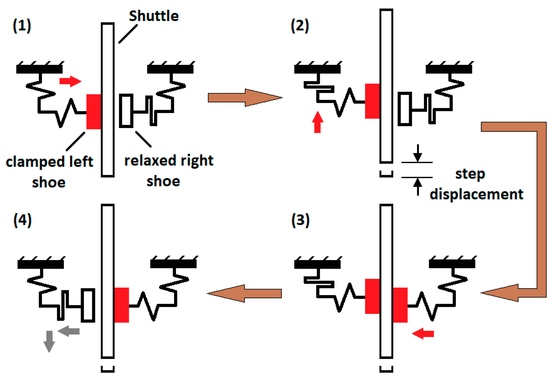
3.2.3. Cooperation through Activated Joints Allowing Stepping Mode

Another architecture of cooperation is based on joints, which can themselves be activated by an actuation, e.g., to actively couple different actuators or actuation actions, to obtain a stepping-like movement by a cyclic activation of the joints, combined with “propulsion” actuations within each cycle. Therefore, these actuation systems enable the realization of even more complex cooperative systems, which will be described in Section 3.3.
An early approach towards a stepping motor employing this concept came in the form of the so-called SDA, which was first investigated by Akiyama et al. [10,43]. In this section, we focus on the basic structure of a SDA, which consists of a polysilicon plate with a “scratching” bushing at one of its ends (Figure 8a).
The SDA structure is defined by surface micromachining on a Si-substrate with an insulating film as a passivation coating as well as a suitable “gliding/scratching” surface. The cooperative action that produces a stepping-like movement is provided by different functional elements within the SDA, combined with an appropriate sequence of applied electrical potentials, as shown in Figure 8a. By applying a potential between the plate and the substrate, the deformable plate bends towards the substrate in the first phase of the increasing potential by pull-in, in such a way that the free end of the plate is pulled down onto the surface. Thus, the contact area of the previously free end provides a mechanical grip to the substrate’s surface. At the same time, friction forces between the bushing and the substrate’s surface prevent a movement of the bushing tip, as a result, the bushing creates a warp in the plate and an elastic strain energy is temporarily stored in the deformed plate, in the so-called priming phase. By further increasing the driving voltage, both the contact area between the plate and the insulated substrate (directly proportional to the “clamping” force of the plate to the surface) and the elastic strain in the rest of the plate increase. Finally, at a certain stepping voltage the bushing is pushed forward (scratches) by the built-up elastic energy, while the previously free, left end of the plate remains still because it is “electrostatically clamped”. When turning off the potential, the left end of the plate is de-clamped and the stored elastic energy is released (at least so far as no stiction is occurring). As a result, the now again-free left end of the plate is pulled towards the bushing. Thus, the SDA moves in a step-like movement over the surface. In [43], the SDA is suspended with torsional beams to a frame-like anchored structure (not shown in Figure 8a) in order to transfer the step of the SDA structure to the higher-level system. Step sizes of 10–80 nm depending on the bushing height (1–2 µm) and applied peak voltage (30–200 V) were reported [10].
In 1997, Akiyama et al. [46] integrated a single SDA into a more complex mechanical system. By connecting the SDA via a link frame to a buckling beam, the movement of the SDA is transmitted to the beam structure, which then changes the deformation of a pre-buckled beam (out-of-plane movement) and thus can be used for the actuation of macrosystems. By the link frame, the steps of the SDA were successfully transferred to a buckling beam, where the relation of SDA displacement and deflection of the buckled beam is depending on the beam geometry and can be therefore adjusted (e.g., different deformation, gear amplification and force transmission are possible). The authors reported a 10 µN force and 100 µm displacement in the z-direction. This is therefore an example of cooperation between one simple actuator (SDA) and a suitable mechanical structure to provide new functions, such as the capability of achieving defined xyz-movements of originally planar actuation architectures or deformation or force amplification.
Li et al. [47] estimated the forces generated by spring-loaded SDAs from the maximum achieved spring deflection. The stiffness coefficient of the employed box springs was determined by FEM analysis. With an applied voltage of 200 V, forces of 250 µN and 850 µN were estimated for one-plate and four-plate SDAs, respectively, thus proving the concept of a force amplification by cooperative action of four SDAs. Additionally, modeling approaches and theoretical grounding attempts concerning the performance characteristics, dynamics and force estimation of SDA implementations can be found in [48,49,50].
Linderman et al. [44] optimized the driving signal as well as the geometry of SDAs by analytical modeling. Moreover, they implemented SDA actuators in large arrays to form a rotary motor driven by nine SDAs, and a tethered robot made up of 188 SDAs that are driven in parallel, thereby proposing a more advanced cooperative architecture. The robot was capable of pushing a (2 × 2 × 0.5) mm3 silicon chip over a distance of 8 mm. Additionally, more robots could be assembled on a ceramic stage to achieve multiple degrees of freedom and bidirectionality. Thereby demonstrating that by integrating a large number of cooperative SDAs, the system performance can be improved considerably. In addition to the xyz-stage introduced in Section 3.2.1 (Figure 4) [25], other applications, in which SDAs were implemented can be found in [51,52,53].
Even though the basic structure of a SDA and the cooperation therein looks simple, the specific performance is depending on many parameters, which cannot be controlled directly by driving conditions or geometrical design parameters, e.g., the friction between the SDA and the substrate surface is very sensitive to surface roughness and humidity.
These limitations are overcome with another design of electrostatically activated stepping mode, the so-called shuffle motor, which was first presented by the MESA Research Institute, University of Twente. The schematic actuation cycle is shown in Figure 8b. Here, two poly-Si layers were used for an electrostatically driven stepper motor: The first thin layer defines the actuator plate, and the thicker one defines the frame, to which the plate is suspended at two ends. The two ends can be clamped to the substrate (electrostatically activated friction) individually by electrostatic forces between the clamps and the surface. In between the clamping activations, the deformable plate is also electrostatically deformed, creating a strain in the plate, which then pulls the not clamped end towards the clamped one [45,54]. Different from the SDA, the concept provides balanced and well-defined clamping conditions at both ends of the deformed plate. Therefore, the shuffle principle allows the design of more complex inchworm-like motors, which will be discussed in Section 3.3.2.
Another type of stepping mode is obtained by means of an oblique mechanical impact that is transferred from an electrostatically driven resonant structure working as a so-called converter to a circular microrotor, as presented in [55], where two different designs were described, the so-called bi-modal and mono-modal angular vibromotors. Due to the oblique design, by vibration of the converter beams, the rotor, as a passive element, is actuated by tangential friction in combination with a normal impact transfer. In the bi-modal mode, the converter beam can be operated at two primary modes of excitation, which are produced by two separate comb drives that are connected by a bi-modal flexure with the converter beam. Through a pointer tip at the end of the converter beam, the linear oscillation of the converter is transferred to a rotational movement of the microrotor. As the bi-modal converter can be operated at two different primary modes of vibration, it is possible to actively choose the contact sides at which the conversion takes place, and thus the direction of rotation of the rotor. Furthermore, the rotor turning speed can be tuned by adjusting the phase between the driving primary modes, the voltage applied to the combs or the frequency. Thus, a cooperative action of the comb drives and the activated friction is utilized. In the mono-modal vibromotor, two opposing converters are cooperating to actuate the rotor. In this way, the cooperative action is similar to the linear drive shown in Figure 2.
A similar approach of oblique impact transfer was used by Daneman et al. to realize a linear microvibromotor [56]. Here, the impact of four comb resonators was transferred to a slider, which was placed between the impact arms at an angle of 45° to each of them. Two opposing impact arms were used for each direction, thereby accomplishing a bidirectional drive of the slider. A travel range of more than 350 µm was achieved.

3.3. Advanced (Strong) Cooperative Architectures

In this section, cooperative actuator systems consisting of usually many actuators, which have individual excitations for each of them and strong interactions among them, e.g., those featuring hand-over actions, will be reviewed. Inchworm motors are an evident example of such systems; thus, a particular review of their development over the years is provided. This section will be concluded with an overview of recent systems that exhibit even more elaborate cooperative systems, mainly those integrating many inchworm motors for robotic applications.

3.3.1. Microtransportation Systems

The research in the fields of micromanipulation and microtransportation has increased considerably in recent years, partly to cope with the needs of other emerging miniaturization technologies, such as in a micro-assembly application or a micro total analysis system (µ-TAS). Consequently, as mentioned previously, microgrippers [30] and micromanipulators [29] have been proposed. Another noteworthy contribution to this field is the micro transportation system (MTS) by Pham et al. [57]. Their micro conveyor system is an exhibit for cooperative actuation, which comprises many linear and rotational comb-drive actuators that use the ratchet mechanism to drive so-called microcars in straight and curved paths. The system, which consists of several types of modules: a straight module, a turning module, and a separation module (an actuated T-junction), is fabricated using SOI-technology with a device layer of 30 µm and a buried oxide layer of 4 µm. A construction similar to these modules (but of a different actuator design) is shown in Figure 9a. The comb-drive actuators and microcars have sidewalls in the shape of saw teeth, which make up the ratchet mechanism. The comb electrodes are driven with DC-biased sinusoidal signals with VDC = ½ VPP, which results in a reciprocating motion of the ratchet racks along the direction of the channel they form. Moreover, a microcar has sliding joints and serpentine springs that allow the microcar’s width to vary while being propelled forward. The racks opposite to one another in a channel move with 180° phase shift. As a result, one ratchet rack on one side pushes the microcar forward, while the rack on the other side slides over. If the applied driving voltage is larger than a certain critical value, in the case of the straight module, both ratchet racks will move the car during the actuation cycle, albeit one ratchet actuator moves it by the electrostatic force, while the opposite one uses the restoring elastic force of its deflected beams. The curved-path modules have only one actuated side. Results of successful runs of the straight movement were reported, where a voltage (VPP) of 150 V was applied with frequencies ranging between 5–40 Hz, which corresponded somewhat linearly to microcar velocities ranging between 54–512 µm/s.
Later the same group proposed another design for the MTS, in which the same types of transportation modules were included (Figure 9a); however, in this design, the actuators’ ratchet racks had an inward reciprocating movement that “squeezes” the microcar (also referred to as the ‘micro container’) [58]. Moreover, the microcar exhibited a more elaborate design, which instead of the ratchet racks it had in the previous design, was now fitted with two pairs of ‘anti-reverse wings’ and ‘driving wings’ (Figure 9b). The latter pivoted off a spring-supported rotational joint, which when squeezed, rotate backward to generate a reaction force to push the microcar forward, at the same time, the anti-reverse wings serve as a ratchet mechanism and prevent the backward movement of the microcar. A variable travelling velocity of up to 1 mm/s of the microcar was reported, and within a certain applied voltage window (140–160 V) smooth and stable movement through all three types of modules was demonstrated. The system was also fabricated using SOI-technology, with one photolithography mask for a DRIE etch, followed by vapor-phase hydrofluoric acid release. A close-up view of the fabricated microcar can be seen in Figure 9c. Here, a sophisticated cooperation of many actuators and elaborately designed structures, including the microcars, was demonstrated.

3.3.2. Inchworm Motors

The inchworm motor is another cooperative mechanism, the history of which goes back to the 1960s, as the survey by Galante et al. showed [59]. This motor system integrates several actuators to generate large displacements by adding up small steps through a scheme of repeated clutch-drive actuation. The main motivation behind the early propositions of these motors, which typically made use of piezoelectric actuators, was producing high-precision positioning devices, e.g., for precise machining or in scanning electron microscopy. Recently, this linear actuator mechanism has established a strong foothold in the electrostatic realm after increasingly being the subject of research from the 1990s to this day. In this section, many of the contributions made over these years will be viewed, generally in a chronological order; however, as some of the inchworm motors belonged to certain sub-groups, e.g., the shuffle motor (introduced in Section 3.2.3), once introduced, the development of such a group will be viewed as a whole. The electrostatic inchworm motors can be classified, similarly as per the survey by Galante et al., according to their setup into a “walker” type, or a “pusher” type. The former refers to a scheme in which the propulsion actuator is embedded in and moves along with the shaft, whereas the latter indicates that the shaft is driven by a separate, stationary propulsion actuator. From a technological perspective, inchworm motors can also be classified into bulk micromachined/crystalline silicon (c-Si), surface micromachined/poly-Si and SOI/c-Si.
In 1995, several different electrostatic inchworm motors were introduced [60,61,62]. The one proposed in the pioneering work of Lee and Esashi [60] featured a thick (~200 µm), suspended rotor having the shape of a ladder with tightly spaced steps, which is fabricated by bulk micromachining technology. The rotor is sandwiched with a separation of few micrometers between two fixed plates, made of pyrex glass, which are equipped with strips of thin-film conductors that define the stator electrodes. The electrodes have a certain grouping and a phase shift configuration and use the alignment force component to drive the rotor in one of two directions, hence it is a pusher-type mechanism. Here, the motor had an inchworm-motion type of actuation based on four phase voltages with a step distance of 1.5 µm. The authors claimed to have achieved a force of few mN and a speed of 13 cm/min with 100 V driving voltage at a frequency of 1.4 kHz.
Yeh et al. [61] proposed another stepper motor of the pusher type to drive articulated 3D polysilicon robotic limbs made by surface micromachining. To generate large forces, the motor was designed with comb-drive, gap-closing actuators (GCAs). In one version, the motor had four comb drives, two situated on each side of a shuttle. Every comb drive is fitted with a shoe-like structure that could clamp to the shuttle electrostatically (Figure 10). The two comb drives that are opposite to one another cooperate to propel the shuttle by a specific clamp-drive sequence in one direction. Thus, bidirectional actuation is achieved by having another pair dedicated to the opposite direction (not shown in Figure 10). A comb drive is able to pull the shuttle a distance of 2 µm, which is the gap between the comb electrodes. Figure 10 shows a schematic of the sequence of operation for one half of an inchworm cycle, which is a typical sequence for such a pusher-type inchworm motor. It was estimated that the force generated by the motor was about 6.5 µN while being driven at 35 V. Additionally, the shuttle was moved by a distance of 40 µm by 10 full inchworm cycles before an anchoring spring was broken.
As briefly discussed in Section 3.2.3, the shuffle motor principle was firstly proposed, also in 1995, by a group from the MESA research institute [62], which is another type of polysilicon surface micromachined linear motor that could be considered as a subclass of inchworm motors. The concept of operation shown in Figure 8b indicates that it is of the walker type. After an improved design of the motor, fitted with anti-sticking bumps to overcome the initial sticking problems, and supported with a comprehensive model description, a successful implementation of the motor was realized using three polysilicon layers [45]. The motor provided a high resolution displacement with a step size of about 85 nm and a maximum reach of 43 µm. A force of 43 ± 13 µN was achieved with 25 V and 40 V of driving voltages for the bending plate and clamps, respectively. It is worth noting that the clamps had to be driven by AC voltage to avoid sticking, which in turn increased the slipping and reduced the effective generated force. A displacement speed of 100 µm/s with a driving cycle frequency of 1160 Hz was attained. The attractive features of a shuffle motor, such as inherent bidirectionality, very high precision positioning capability and theoretically unconstrained movement, have garnered a great deal of attention and investigation [64,65,66]. Furthermore, Sarajlic et al. [67], using trench isolation technology, had further developed the shuffle motor into a 2-DoF planar motor with drastically improved performance characteristics, such as a larger force (0.64 mN) at moderate operating voltages (up to 45 V), an adjustable nanometer-resolution (step size of 41–63 nm), and a cycling frequency of up to 80 kHz.
In 2006, Sarajlic et al. [68] also proposed the “contraction beams micromotor”, which is fabricated using surface micromachining and trench isolation technologies as well, and has a built-in mechanical transformation that is similar to the shuffle motor. However, rather than contracting a plate to the substrate, an array of pairs of electrically isolated beams are contracted to one another, such that the pulled-in contraction is transformed in the same plane, contracting the clamping electrodes by a much smaller distance (a step of 10 nm) with a measured large force (0.49 mN) at an actuation voltage of 60 V. This mechanism reduces some drawbacks resulting from contracting the shuffle motor’s plate to the substrate, namely, the unwanted induced frictional force at the inactive clamp electrode, and the compromising moment that reduces the clamping force of the activated one.
In 1997, Tas et al. [69] proposed an inchworm motor fabricated with a single-mask surface micromachining process. However, this motor is of the pusher type, and it employs an actuator mechanism similar to Yeh’s [61], where a pair of shoe-like structures pull a shuttle sandwiched between them. In this design, two shoes are driven by two cooperative driving units, each consisting of two comb-drive GCAs that have separate actuation beams, which make a right-angle joint at the shoe; one beam clamps the shoe to the shuttle and the other pulls it. The sequence of operation is similar to the one shown in Figure 10, except that the clamping force is frictional rather than electrostatic. The 5 µm high polysilicon structure generated an estimated force of 3 µN in a maximum step size of 2 µm and a total displacement of 15 µm at a driving voltage of 40 V with one cycle of operation per second. However, the asymmetric, parallel spring suspension of the shuttle, combined with a single-sided clamping during propulsion was a limiting factor of the deflection and resulted in a reduced clamping force and an increased slipping as the shuttle moved forward. In the same year, Baltzer et al. [70] proposed a similar inchworm motor with twice the amount of driving units, which provided a double-sided clamping (gripping) of the shuttle during propulsion. The driving units had an in-line design, such that the clamping and driving GCAs were both integrated on a single rigid beam, which had a folded-beam suspension on one end and engaged the shuttle by the other end. Two variants of the motor were presented, one was fabricated using two polysilicon layers and featured a suspended shuttle that also managed a maximum displacement of 15 µm, and the other one had a suspension-free shuttle with tighter clearances that required three polysilicon layers, which achieved a total displacement of 110 µm, being limited only by design. The driving units for both variants were identical. Depending on the applied voltage (15–40 V), the motor could achieve a stepping motion both before and beyond the pull-in point, with the former allowing more exact positioning. The calculated force at an applied voltage of 20 V was >1 µN.
At the beginning of the 21st century, an evolution in the fabrication of such inchworm motors was taking place, marked by the many works that sought the use of crystalline silicon (c-Si) as the building material, in particular with SOI-technology, to fabricate these motors in HAR actuator form. An early example of this development is a pusher-type inchworm motor proposed by Yeh et al. [11], a group that had previous contributions of inchworm motors fabricated with surface micromachining, e.g., [61,63]. The motor had two driving units on one side of a shuttle. The unit consisted of a clutch GCA array, which when activated, brings a frame that encloses another “drive” GCA array in contact with a shuttle to drive it. At the time, their work had pushed the envelope of force generation for such motors by achieving a force of 260 µN with an applied voltage of 33 V. The higher force density was achieved primarily by the higher aspect ratio actuators (up to 25:1). One demonstrator was fabricated out of a 50 µm thick device layer, limited by the elastic restoring forces of a suspended shuttle, it managed a maximum displacement of 80 µm in 2 µm steps. Another, 15 µm thick demonstrator was driven at a frequency of 1 kHz (theoretical limit was 1.4 kHz) and achieved an average speed of 4 mm/s. To guarantee a sufficiently robust transfer of forces to the shuttle and reduce slippage as much as possible, this motor featured interdigitating teeth as a mechanical clutching interface between the driving units and shuttle. Nevertheless, when driven at frequencies higher than 1 kHz, the authors reported some slipping between the clutch and shuttle. It is worth noting that despite using bare silicon teeth for mechanical clutching, motors were operated for more than 20 million cycles, corresponding to 13 h of active operation.
Using driving elements that serve as clamp and propulsion actuators at the same time has been tried before, such as the so-called design A in [71], but unsuccessfully. In 2013, Penskiy et al. [72], proposed an inchworm motor design that merged the traditional clamping (or clutching) and driving mechanisms into one movement. Using an inclined, flexible arm, fitted with a teethed small block at its end, the unidirectional movement of a comb-drive GCA, which is perpendicular to the shuttle, is transformed to a simultaneous clutching and pushing of the shuttle. In this respect, the design is also reminiscent of the linear vibromotor [56], presented previously in Section 3.2.3. To balance the lateral forces, the shuttle is sandwiched between a pair of comb drives that is driven simultaneously, which together with another pair actuate the shuttle consecutively to cause the typical inchworm pushing sequence. Figure 11 shows a SEM image, presenting the layout of the inchworm motor, which achieved a maximum shuttle velocity of 4.8 mm/s at an actuation frequency of 1.2 kHz with a step size of 2 µm, and a force of 1.88 mN at a driving voltage of 110 V.
In 2021, Narimani et al. [73] presented a highly modular, pusher-type inchworm motor based on the NED actuator concept, which has been previously introduced in Section 3.1.3 as an example of a cascaded actuator system. However, instead of an out-of-plane cantilever deflection, here the S-shaped NED actuators have an in-plane deflection to provide the shuttle propulsion mechanism. A stack of NED actuators makes up a driving block, which can have one of two fixed deflection directions depending on the layout of the NEDs within. Hence, the system also features bidirectional actuation. The shuttle is sandwiched between pairs of NED blocks, which clamp to it electrostatically. The shuttle is suspended by four serpentine flexures. The motor system is realized by c-Si on an SOI wafer using typical HAR silicon micromachining processes, such as DRIE, in addition to atomic layer deposition (ALD) to form insulation islands between the NED electrodes. A maximum shuttle displacement of about 1 mm was achieved with a maximum step deflection of 11.8 µm, by applying 150 V and 130 V for electrostatic clamping and NED driving, respectively. It was estimated that a single NED block with 36 S-beams is capable of producing a maximum force of 0.8 mN.
The authors of this review are also working on a bidirectional, multistable inchworm motor system of the pusher-type, which is based on the cooperation of two actuator subsystems, the mobility transmission electrodes (MTE) and the actuation unit cells (AUC), as shown in Figure 12 [74]. Some details about the system’s design concept can also be found in [75]. The purpose of the MTE is to provide multistability to a shaft, whereas the AUC engages the shaft to push it. The modular design of the system aims at providing scalable displacements (several mm) and force capacities (tens of mN). The shaft is composed of two sliding beams that are initially interlocking a central, stationary holder via mechanical suspension springs. The MTEs, placed at both sides of and parallel to the sliding beams, provide electrostatic forces to pull them apart and release them from the stationary holder. When the shaft is freed by the MTEs, the outer shafts’ teeth become clutched by those of the AUCs, and a linear movement can be realized by a sequential actuation scheme of the AUCs, which are divided into groups. The AUC is a 2-DoF actuator that is able to both clutch with the main shaft as well as actuate it in either one of the two directions along the shaft. It is worth noting that the multistability feature is a unique capability of this inchworm motor that is rarely found in other inchworm motor realizations, which necessitates the cooperation of another distinct subsystem: the MTE. The multistability in this context is the ability of the shaft to assume multiple positions along its displacement range that are stable in the absence of power. It is of a discrete nature, since it is defined by the inner teeth of the shaft, which in turn defines the stable, interlocked positions the shaft could have with the stationary holder. Furthermore, the shaft is envisioned to be fully untethered by employing proper guiding structures, such as mechanical stoppers and a covering plate, for constraining sideways and out-of-plane deflections, respectively.

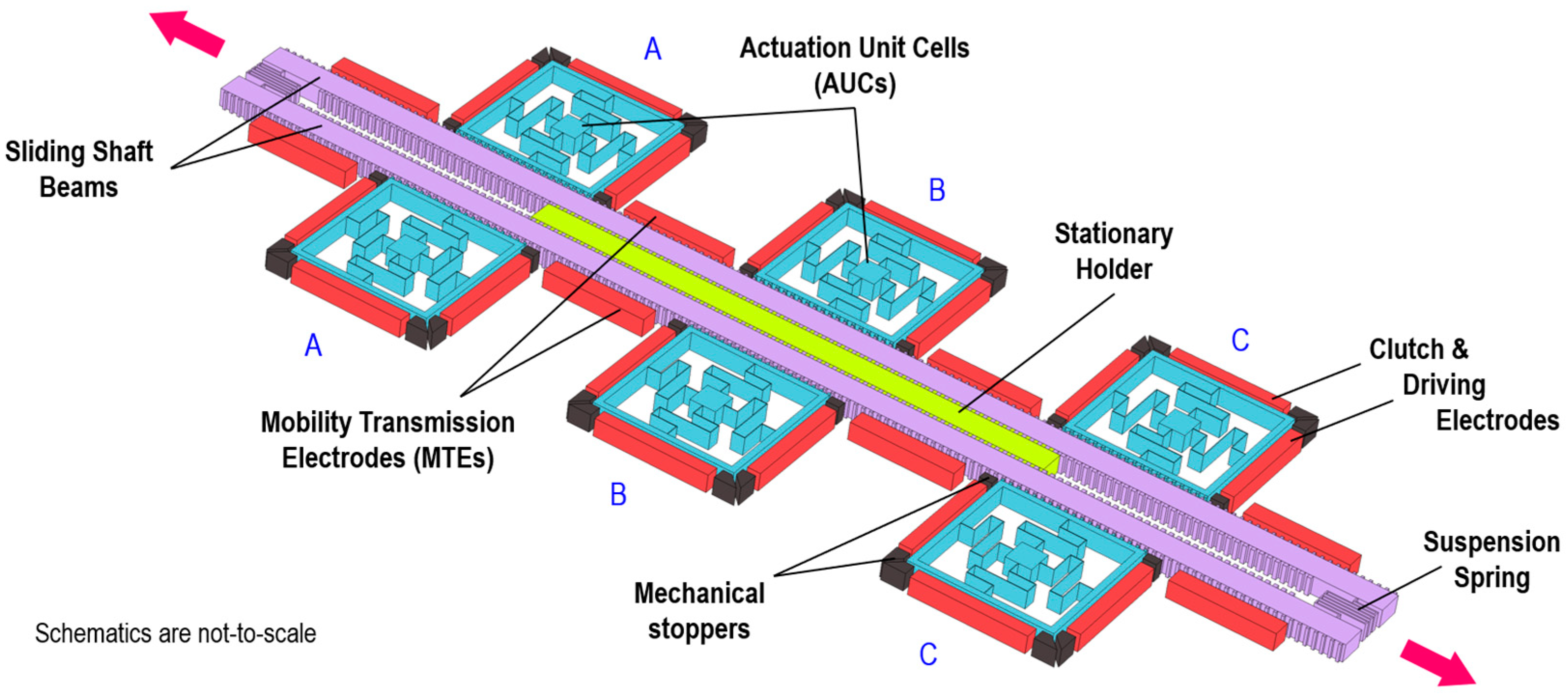
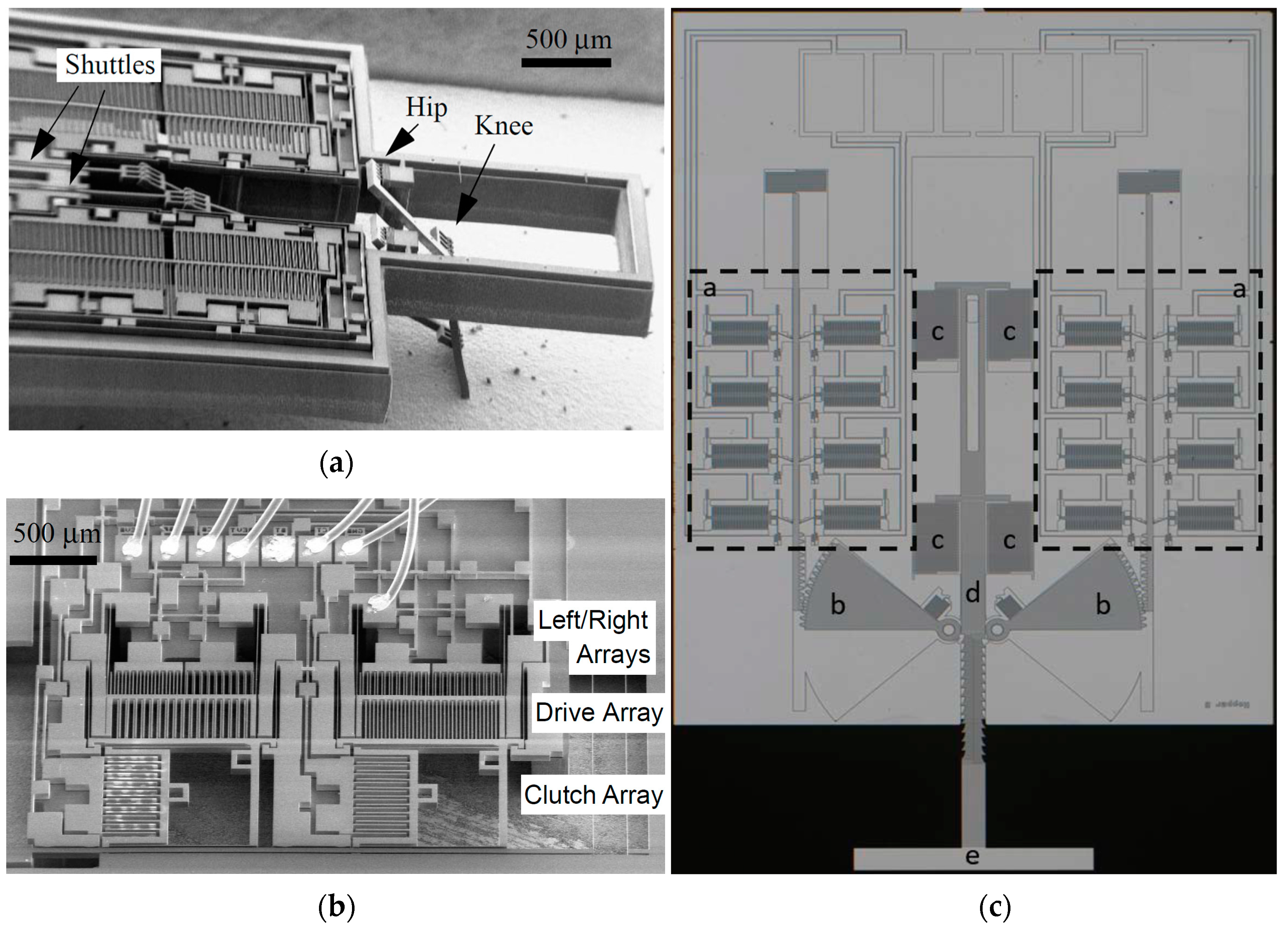
3.3.3. More Elaborately Cooperative Systems

An example of an even more sophisticated implementation of inchworm motors, which highlights the potential of such cooperative systems, is the contribution from Hollar et al. in 2003 [76]. This work had integrated essentially the same design of the inchworm motor found in [11] into a 2-DoF robotic leg, which is shown in Figure 13a. Both works emerged from the same research group. In addition to SOI technology, joints and crossover beams were fabricated by polysilicon-based micromachining. With a total displacement of 400 µm and shuttle speeds of up to 6.8 mm/s, improvement of the performance characteristics of the motor was apparent. However, more noteworthy was accomplishing the bidirectional actuation necessary for this application, which was demonstrated in two ways. The simpler approach, that is reversing the control sequence of the inchworm motor and using the elastic restoring force to drive the shuttle, which was enough for driving the robot leg, or by introducing biasing comb drives that determine the actuation direction of the drive GCA, a mechanism that provides equal forces in both directions but complicates the operation with the two additionally required signals. As a result, the latter was only demonstrated by a test structure (Figure 13b) but not implemented in the robot.
Following the novel implementation of the flexible, inclined arm to drive the inchworm motor’s shuttle that was proposed by Penskiy et al. in 2012 [72], several more complex cooperative systems have used this optimized design and made it somewhat of a blueprint for more advanced inchworm motor implementations, such as a so-called ‘inchworm-of-inchworms’ motor topology with force amplification for a jumping microrobot by Greenspun et al. (Figure 13c) [77]; a MEMS airfoil actuator by Kilberg et al. [78]; another jumping microrobot by Schindler et al. [79]; an aerodynamic control of miniature rockets by Rauf et al. [80]; a microgripper with 15 mN of force and 1 mm of displacement by Schindler et al. [81]; and a remarkable, intricate realization of a cooperative electrostatic actuation in the form of a multichip terrestrial robot developed by Contreras [82]. In the latter, each leg of the six-legged robot had a 2-DoF planar silicon linkage, featuring rotary joints, that is operated by two separate inchworm motors. The construction of the robot legs is similar to the one found in [83]. Therefore, the multichip robot has 12 motors, 6 linkages and 12 degrees of freedom in total. The robots walking was demonstrated after externally supplying it with power and control signals via connected wires [82].
In Appendix A, a table listing some of the electrostatic linear motors reviewed in this paper, with comparison of their operational and performance characteristics as well as the technology used for their fabrication, is given.

3.4. Hybrid System Architectures for Cooperative Actuation Systems

The cooperative microactuator systems presented so far are driven purely electrostatically and the three subsections were addressing the different level of cooperation of these systems. As a last type of electrostatic cooperative actuation systems, hybrid system architectures that combine electrostatic actuation with other types of actuation principles are reviewed in this section. The examples cover different levels of cooperation, including even inchworm implementations. This Section is also a kind of link to other review papers of the Special Issue on “Cooperative Microactuator Devices and Systems”, which describe cooperative microactuators using purely other actuation principles. In this section, we will begin by introducing the motivation for and benefits of such hybrid cooperative actuation systems. The specific examples present architectures in which electrostatic actuators are cooperating with thermal (electrothermal, allotropic phase transformation and thermal pneumatic), piezoelectric and electromagnetic actuators.
One purpose for such hybrid cooperative systems is to introduce a bidirectional mode, where for one direction, the common electrostatic actuation is used, while the movement in the opposite direction is triggered or performed by a separate principle. Another motivation for hybrid cooperation actuator systems is to bring bistability into the system, which is in many cases a precondition for a reliable function of such systems. Additionally, such hybrid cooperative systems can overcome the inherent constraints of pure electrostatic actuators, which are in most architectures, as previously discussed, the limited stroke and force. Furthermore, hybrid systems are also used for closing the gap between micromachined, electrostatic MEMS actuators and the “macro-world” tolerances, e.g., those of the standard machining techniques.
In many hybrid actuator systems, the additional non-electrostatic actuation principle is just supporting the action of the primary electrostatic actuator, especially by bringing the electrodes close together, such that the electrostatic actuation can take over or be used for a hold function with very little power consumption. Early examples were shown for radio frequency (RF) MEMS switches based on a variable capacity, where additional actuation principles work in series with the electrostatic actuation to allow a lower driving voltage for electrostatic switching, by reducing the gap between the movable and fixed electrodes with the extra actuator [84]. In this way, hybrid systems help to overcome the limitations due to the scaling law discussed in chapter 1, which requires even with very sophisticated, deformable electrodes, such as those shown in Figure 3a, at least at some locations, electrode distances in the range of µm and below. With the support of the additional non-electrostatic actuators, the typical problems of pure electrostatic actuation, such as stiction upon pull-in and dielectric charging can be overcome, while keeping its advantage of low power consumption, e.g., for high frequency switching.
For example, in [84], an additional thermal actuator was integrated to support the primary electrostatic actuation. This approach was analyzed further with suitable models in [85], where the concept of a bidirectional actuator that combines electrostatic actuation with thermal actuation was presented as a so-called electrothermomechanical (ETM) actuation. By an appropriate beam design, it was possible to achieve a bidirectional movement, in this case provided by the cooperative action of electrostatic and electrothermal forces. The layout allowed active control of the different states by changing the potential boundary conditions. However, the reported stroke of the bidirectional actuator was only about ±1.5 µm.
A similar approach of combining electrothermal and electrostatic actuations is described in [86]. Here, by a 2nd metalization layer, a bidirectional switching is already obtained with the electrothermal actuation alone, whereas the electrostatic actuation provides the holding state with a low-power consumption. The layout is a standard cantilever supported by four beams, which are realized with the two separate metalization layers. Two beams are dedicated for downward movement and the other two for upward movement. The electrostatic “holding electrode” (membrane) is formed by the 2nd metalization layer. A thermal switching time of 47 µs was reported; however, it required an electric current of 0.23 A, whereas the measured electrostatic switching time was 4.5 µs at an applied voltage of 15.4 V; therefore, the electrostatic switching time was 10× shorter than its thermal counterpart. The total power consumption was 3.24 µJ per switching cycle.
Another concept of cooperative actuation using thermal principles was proposed in [87], where many SDAs, similar to those described in Section 3.2.3, are connected to a shape-memory alloy (SMA) wire to achieve a 3D movement of a catheter by combining the rotational movement provided by the highly integrated electrostatic SDAs (array of 1430 SDAs to create a reasonable torque) with a macro flexure movement by the SMA wire. SMAs make use of the allotropic phase transformation within certain materials, such as Ti-Ni, which was used in [87].
A cooperation of a current-driven thermopneumatic actuation with an electrostatic actuation for a microvalve is described in [88]. Here, the fluid on the inlet side of the microvalve is heated up by a suspended resistor grid. The rising pressure pushes the valve diaphragm towards the valve seat. However, the final closure of the outlet valve is provided by an electrostatic pull-in movement. An electrostatic latch at the outlet opening is also used to detect the pull-in state of the diaphragm, such that the electric power of the pneumatic actuator can then be reduced or even turned off. The motivation for the cooperative design of the valve was achieving a large throw (i.e., large travel distance for closing the outlet valve to provide large flow in the open state), a low leak rate (especially critical with particles in the fluid larger than, e.g., 30 µm, if only electrostatic actuation is provided), a power reduction (compared to an exclusively thermopneumatic-driven actuator) and a fast response time. However, in the presented layout, complete electrostatic latching was not achieved. The authors suggested several design changes to reach electrostatic latching; however, no functional device was presented to the best of our knowledge.
In [89], a piezoelectric support of an electrostatic RF MEMS variable capacitor for RF-switching was proposed. Here, a thin film of lead zirconate titanate (PZT) was embedded in a sacrificial layer process. The piezoelectric actuator supports the pull-in-type electrostatic actuation to increase the capacitance and allows a lower switching voltage (pull-in voltage is considerably reduced), while keeping the pull-out voltage almost constant, which is important to maintain high restoring forces. Thus, by lowering the operation voltage, stiction and dielectric charging are reduced in the hybrid design.
Hybrid concepts with piezoelectric actuation have also been employed for realizing inchworm motors. For example, in 2004, Toda et al. [90] presented a proof-of-concept, hybrid inchworm motor for extended out-of-plane actuation. It utilized in-plane electrostatic forces to alternately clamp a moveable platform to either a driver plate or stationary structures (holders). When clamped to the driver plate, which is driven in the Z-axis by an external piezoelectric actuator, the platform gains a small elevation, then the platform is clamped to the holders to maintain the gained elevation, while the driver plate, i.e., the PZT actuator, is reset to the initial position to start a new cycle. Although the system was realized by a 50 µm thick device layer of an SOI wafer, the motor could only achieve about 0.5 µm of elevation in 10 actuation cycles. Later in 2007, Toda et al. [91] proposed another hybrid inchworm motor combining electrostatic actuation for clutching a slider and piezoelectric actuation for pushing it. The operation and the realized system are shown in Figure 14. The system consists of two electrostatic clutching units (A and B) and a PZT-stack actuator. Unit A is stationary, while unit B is fixed to one side of the PZT actuator, whose other side is fixed to the substrate; hence, unit B can be translated back and forth. Therefore, the PZT actuator can drive the slider in a bidirectional manner, while it is clamped by unit B (see Figure 14a). This cooperative inchworm motor features a power-free clutching by the actuation units A and B, which is achieved by mechanically prestressing the tether beams that suspend the clutching structures in these units. This prestressing results from inserting a slider of a width that is slightly larger than the space available between the clutching structures, which are driven by the movable electrodes of four opposing comb drives on both sides of the slider. This provides a zero-power latching and thus a secure operation. The PZT actuator created a defined step size of 59 nm/cycle and a large force to overcome the residual friction when powering the electrostatic clamps. By FEM, a clutching force of 4 × 4 mN = 16 mN was simulated, where the basic clutching force of 4 mN is a result of the attractive electrostatic forces (40 mN), the repelling bending forces of the tether beams (20 mN), and a friction coefficient of 0.2 ((40 − 20) mN × 0.2 = 4 mN). The MEMS part consists of c-Si, which is fabricated using a SOI-process.
A hybrid actuation system with cooperation of electromagnetic and electrostatic actuators for a miniaturized contactless levitation system was presented by Poletkin et al. in 2015 [92]. Two coils provide induction based forces, one for levitation, the other for stabilization of the levitated proof mass during levitation. The electrostatic forces provided by two different electrode arrangements take over additional functions. Firstly, under pull-in, the electrostatic actuation works oppositely to the electromagnetic levitation force. This means that by keeping a certain levitation height even with increased induction current, a larger voltage can be applied. Therefore, the electrostatic force will change the effective stiffness of the contactless electromagnetic suspension. Additionally, electrostatic forces are used for vertical and angular actuation of the proof mass. 3D microcoils obtained by means of a wire bonder were assembled on a Pyrex substrate, whereas the electrostatic actuators were realized on a Si wafer with DRIE etching of both sides of the wafer. Currents for electromagnetic actuation of 100–130 mA provide levitation heights between 30–189 µm. The measured stiffness of the angular stiffness changed by electrostatic actuation by more than a factor of 2 (from 0.9 × 10⁻⁸ Nm/rad to 0.4 × 10⁻⁸ Nm/rad). Model descriptions of that system considering both, inductive and electrostatic forces were later provided in [93,94].
A similar concept was also presented in 2015 by Sari et al. [95]. Electromagnetic levitation and stabilization are cooperating with an electrostatic propulsion drive of the levitated object. However, here Lorentz forces through an alternating current were used to generate electromagnetic forces. Therefore, electromagnetic and electrostatic actuators could be realized on one silicon wafer.

4. Discussion

While the possibility of even 3D-like motion by planar, surface micromachined structures was already shown by researchers more than 20 years ago [13,25], none of these have been commercialized due to their sophisticated mechanical function, especially the needed hinges to provide the out of plane motion. Therefore, we conclude that a key point to cooperative electrostatic microactuators is how to create bistability and even multistability in such systems. However, only a very limited numbers of papers were found, where functional, electrostatically driven bistable microactuator systems were presented. Ongoing research on the theory and models of electrostatic bistable systems, which is documented, e.g., by several actual papers describing the bistability conditions in arched microbeams or microplates, shows that this is still a topic of fundamental research. We conclude that especially snap-in and snap-out is a critical aspect and hard to control by electrostatic actuation under the pull-in regime.
Due to these limitations, which hold especially true for pure electrostatic cooperative actuator systems, hybrid systems could in theory be expected to play an important role for large force applications and for providing bistability. However, such hybrid systems, which combine different types of actuation principles, have their own technological challenges, and it is much more difficult to create a system model of them compared to pure electrostatic actuators systems. Additionally, with the integration of another actuation principle, which needs specific materials (piezoelectric, SMA, magnetostrictive), the big advantages of electrostatic actuation systems, namely, the CMOS compatibility and scalability for high volume production, are lost. This is not the case for electrothermal actuation. If there are only a few papers dealing with hybrid systems in general, there are, of course, even fewer combining electrostatic and electrothermal actuation. We conclude that a disadvantage of the cooperation of electrostatic and electrothermal actuators is the very different driving principle (voltage versus current driven) and the very large difference in power and reaction time, which make this concept practically not feasible. This conclusion is supported by the fact that most work on hybrid actuation systems was published already more than 10 years ago. Additionally, we observe a lack of continuity in the proposed concepts as mostly only one paper has been published by the according groups. We conclude that despite of interesting features, hybrid systems are sophisticated to realize and to scale up for commercialization and are also not reliable. Even the rather simple—and due to integration in a standard surface micromachining process, also scalable—approach of the piezoelectric actuation cooperating with the electrostatic actuation presented in [89], by the research team of Toshiba, did not pave the way to a commercial product, as today, Toshiba uses a pure electrostatic actuation principle for RF-MEMS variable capacitors [96].
Although electrostatic actuation in principle has large force capability when the gap between the electrodes is reduced, numerous problems and challenges arise when using this gap reduction effect. Besides stiction and viscous damping within small gaps, such systems are very sensitive to environmental conditions, especially humidity and pollution. Additionally, on a submicrometer scale of distances or gaps, also severe technological challenges occur, such as surface roughness of side walls (defining the electrode surface and thus the homogeneity of electric field for driving), which have a strong influence on the devices’ performances.
Other challenges for the realization of cooperative electrostatic actuator systems are related to technological aspects, e.g., in DRIE, which is typically used for the realization of HAR microstructures, the limited anisotropy and several other limitations such as notching [97] have to be overcome for improving the reliability and for further miniaturization. Additionally, as a result of miniaturization, the surface to volume relation is also increasing. Therefore, the overall systems’ properties are mostly defined by the surfaces within such systems, which are hard to control and exposed to major external influences. This is a severe challenge in respect to system reliability, especially when such systems should provide large forces.
Electrostatic motors are examples of strong cooperative architectures, which can overcome the limitations of a stand-alone electrostatic actuator. From their inception, the primary challenged constraint was, especially at first, the inherently limited travel range. Later, the generation of larger forces was also aimed for by many researchers. The high resolution displacement provided by small defined steps can also be a major advantage for high precision positioning applications, which is especially characteristic of some inchworm motor types. Here, we will discuss some of the pros and cons of the different realizations of linear electrostatic motors, with a special focus on the inchworm motors.
The early works on inchworm motors in the mid-1990s were mainly based on poly-Si and typically generated forces in the range of few to some tens of µN. The force density was small, especially in the absence of any unique mechanical leverage. With the establishment of SOI wafer technology, which provides the easily releasable thicker c-Si structures, accompanied by the more optimized HAR silicon micromachining processes, e.g., the DRIE, better performance characteristics could be achieved. For instance, upgrading from a thin poly-Si structural layer to a thicker c-Si device layer of a SOI wafer enlarged the force capacity substantially and solved an adhesion problem between contacting surfaces in [11], which could have been the result of having larger restoring forces by the now stiffer springs, or the reduced adhesion by virtue of the larger DRIE sidewall roughness, as reasoned by the authors.
It is worth noting, however, that some electrostatic motor types that have appealing characteristics have almost exclusively been fabricated in thin poly-Si layers, e.g., SDA and shuffle motors. These motors, in addition to the contraction beams motor, which are based on orthogonal mechanical conversion of force or deflection, have exceptionally high capacity for precision positioning with typically reported step resolutions between 10–80 nm [47,67,68], and could be driven at high frequencies (up to 80 kHz) [67,68]. Additionally, some of these walker-type inchworm motors can be built without a need for guiding rails or mechanical suspensions [44,67], which imposes less constraints on the maximum travel range and direction when compared to pusher-types that usually include suspended shuttles. This also makes the former more suited for realizing multi-DoF and planar motors [53,67]. Furthermore, surface-micromachined motors out of poly-Si could more readily accommodate untethered shuttle configurations in their monolithic fabrication, which lends itself to achieving longer travel distances [70].
Nevertheless, they also have some inherent drawbacks and have shown some typical shortcomings. SDA and shuffle motors rely on a certain frictional component with the substrate in order to function properly. They also require insulated electrodes, and as a result, the dielectric insulation is prone to trap charges (dielectric charging), which influences the friction profile and consequently the device behavior during operation [65]. It could also cause stiction leading to device malfunction [54], or even permanent sticking, which led to destruction upon repositioning in [44]. Furthermore, the typically thin bending plate in these motors imposes an inherent limitation on the maximum generated force due to the induced plate stretching that occurs beyond a certain force level [65]. Additionally, the efficiency of these devices, by design, is subject to question. For instance, large friction forces caused by adhesion forces between inactive clamps and the substrate have been reported [45]; moreover, the bending plate’s deflection towards the substrate in a shuffle motor, causes unwanted friction at the released clamp site, which opposes the motor’s shuffling motion, and introduces a moment at the activated clamp site, which could significantly reduce its clamping force [68]. In addition, in standard surface micromachined motors, the thickness of the functional layer (poly-Si or thin c-Si device layer) is typically an order of magnitude smaller than HAR motors made out of such SOI wafers that have thicker device layers (e.g., >10 µm), this is a substantial drawback for applications that engages mesoscale loads, where the fabrication and force transfer become much more challenging. This conclusion is inferred from the prevailing trend witnessed in recent years towards HAR inchworm motors for applications involving a micro-macro transfer of force and displacement [77,78,79,80,81,82,98].
The use of interlocking structures such as teeth, jaws, pawls, etc., is another easily observable trend in recent years, especially in contributions that aimed for a large force capacity [11,74,77,78,79,80,81,82,98]. This trend was needed in HAR devices as a means for a reliable transfer of forces between the different parts of an inchworm motor, which solved a clutch slipping problem as reported in [11], for instance. These structures produce an impact-induced mechanical wear resulting from the colliding surfaces, which generates less uniformly distributed mechanical loads that lead to higher loading surface stresses, at teeth edges, for example. This is a kind of wear that is additional to other kinds that are associated with the rubbing of sliding planar surfaces found in all types of electrostatic motors, of which the adhesive wear was reported to dominate (as opposed to the abrasive and corrosive kinds of wear) [99]. Although some authors have reported relatively long life spans of their systems with reliable outcomes [11], it is well-understood that the wear in these systems, and the microparticles contamination and debris produced by their operation, have led to rapid loss of efficiency even after a short operation time [82], and sometimes complete device failure [100].
Many of the proposed inchworm motors rely on the passive restoring elastic forces of suspension springs to reset the actuated body, e.g., a shuttle, to its initial position, thereby lacking the capacity of bidirectional positioning. This has been overcome in some other inchworm motors that inherently provide a bidirectional movement mechanism, such as the shuffle motors [62], the contraction beams motor [68], the multi-phase, alignment-based motors [60] and the PZT-based hybrid inchworm motor in [91]. Others have a built-in bidirectionality in the design of the propulsion actuator by having double the amount of driving electrodes [70,74], or introducing a biasing mechanism for presetting the direction of propulsion, with a reported minor influence on the force density [76]. On the other hand, other motors achieved bidirectionality by duplicating the unidirectional cooperative actuators for the opposite direction [61]. An approach that could be viewed as the least efficient utilization of space, should this perspective be critical, e.g., for achieving high force density motors. The NED-based inchworm motor in [73], has two oppositely oriented pairs of unidirectional NED-blocks; however, when one pair of NED-blocks is used to drive the shuttle in a certain direction, the other is used momentarily to hold the shuttle while the former recovers from deflection; therefore, there is an overlap of inherent and duplicate-based bidirectional designs. It is worth noting that the reported successful bidirectional actuation through reversing the control sequence of the inchworm motor in [76] could be a viable option for many other inchworm motors that have suspended shuttles, albeit the generated driving force will not be equal in the two directions.
Though electrostatic linear motors largely perform the same task, depending on their type and configuration, their cooperation-based operation and control entail different levels of complexity, e.g., the number of individual actuators in the system and the number of required control signals. When we compare some of the motors presented in this review from this perspective, we find that SDAs are among the simplest motors to control, since aside from the ground electrode, they are driven in parallel using one signal per direction, regardless of how many SDA plates are integrated in the motor. To remedy the dielectric charging issue, SDAs have been driven with AC signals of alternating sign, whether in pulse [10], square [46], triangular or sinusoidal form [50]. Sometimes to keep them in a primed position for optimized performance, SDAs have also been driven with a DC-bias [44]. On the other hand, inchworm motors, especially the walker-type, conventionally need three control signals to perform a complete cycle, two for the clamping electrodes and one for the driving electrode. This configuration is true for shuffle and contraction beams motors, which typically also uses bipolar, modulated AC potentials to avoid dielectric charging [45]. By reversing the sequence of these signals these motors can move in the opposite direction. The multi-phase, alignment-based motor in [60] used four AC signals to drive the four-phase motor, which are also used for both directions of actuation. Moreover, pusher-type inchworm motors typically require four signals (two for each driving unit: one for clutching/clamping and one for driving) to actuate the shuttle in one direction [11,69]. However, concerning the required added complexity to achieve bidirectionality, the motor configuration discussed in the previous paragraph plays a decisive role. Naturally, the duplicate-based bidirectionality will require double the amount of control signals, i.e., eight. While motors that have integrated bidirectional electrodes in their basic driving units, require one additional signal for each driving unit; thus, some require six different signals for two driving units [70], while others require nine signals for three groups of actuation unit cells, with one more signal to achieve multistability, making the total ten signals [74]. Similarly, the biasing mechanism proposed by Hollar et al. [76] required two additional signals for predetermining the direction of actuation, bringing the total to six signals for each inchworm motor. However, due to this added complexity, the authors preferred the reverse control approach to accomplish a bidirectional drive of their robotic leg, which required a total of eight signals to drive both, the hip and knee inchworm motors. On the other hand, by virtue of the double-purposed driving units, as discussed previously, the NED-based motor requires only four signals to accomplish a bidirectional drive [73]. Another noteworthy novelty in this regard is the control simplification that accompanied the combination of the clutch and driving mechanisms into one movement by an inclined arm, which resulted in a successful unidirectional inchworm motor movement that requires only two input signals [72].

5. Conclusions and Outlook

Despite the ubiquitous electrostatic microactuators that are found and used today in billions of commercial products and devices, systems and commercial examples of highly cooperating electrostatic microactuators are rare, e.g., the micromirror device of TI has a relative simple design architecture with isolated microactuators (electrostatically tilted micromirrors), where the cooperation is basically provided through the driving electronic circuit (CMOS drive logic) and the individual excitation capability within the chip. As such, it is a somewhat “weak” cooperation facilitated on the system level by the capability to drive each of the more than 1 million micromirrors individually to produce an image pattern. Additionally, all micromirrors are actuated in the same way (tilted electrostatically by around ±10°).
We explain the lack of commercial products using strong cooperative electrostatic actuator systems by the planar character of surface micromachining, which, on the other hand, is a prerequisite for the success story of electrostatic actuators in consumer applications.
To overcome the critical wear and microparticles phenomena, when using mechanically interlocking structures, well-grounded research into the durability of these force-transfer mechanisms in HAR actuators with experimentally based solutions, e.g., using functional anti-wear coatings deposited by atomic layer deposition, would be a highly beneficial endeavor for improving the efficacy of these systems in the future.
Just recently, W. Fang reported that thin piezoelectric films, in particular aluminum nitride (AlN) and PZT, have been established in foundries and equipment suppliers in Taiwan’s strong semiconductor industry, thus allowing the integration of these materials in CMOS processes [101]. This might be a game changer, especially for hybrid cooperative actuation systems, as piezoelectric and electrostatic actuators can be monolithically integrated in a large scale production.
The progress of miniaturization towards the nanotechnology will open the path towards controlled gaps in the range of some 10–100 nm, and thus enable much more powerful devices than reported so far. In any case, due to the different challenges, further research is needed to provide reliable cooperative systems, e.g., for large force applications.

Author Contributions

Conceptualization, A.A. and U.M.; investigation, A.A. and U.M.; methodology, U.M.; formal analysis, A.A. and U.M.; resources, U.M.; writing—original draft preparation, A.A. and U.M.; writing—review and editing, A.A. and U.M.; visualization, A.A. and U.M.; supervision, U.M.; project administration, U.M.; funding acquisition, U.M. Moreover, A.A. and U.M. have contributed equally to this publication. However, concerning the inchworm motors in particular, A.A. was responsible for their review, critical analysis and discussion. All authors have read and agreed to the published version of the manuscript.

Funding

This research is funded by the German Research Foundation (Deutsche Forschungsgemeinschaft—DFG) under the umbrella of the priority program SPP2206—Cooperative Multistage Multistable Micro Actuator Systems (KOMMMA), project number ME 2093/5-1.

Conflicts of Interest

The authors declare no conflict of interest. Moreover, the funders had no role in the design of the study; in the collection, analyses, or interpretation of data; in the writing of the manuscript; or in the decision to publish the results.

Appendix A

Table A1. Comparison of the performance and operational characteristics for some of the electrostatic linear motors reviewed in this paper.
YearRef.ActuatorsWalker v. PusherStroke (Step)Max Disp.ForceVoltage [V]SpeedFreq. of OperationUni-/BidirectionalFabrication TechniqueClutch MechanismPropulsion MechanismComment
1993[10]Scratch drive actuator (SDA)Walker(10–80) nm--40–150(10–80) µm/s1 kHzUniSM poly-Si-Plate
bending
1995[43]SDAWalker-~120 µm63 µN±112-50 HzUniSM poly-Si-Plate
bending
2001[44]SDA robot (Scratchuator)Walker30 nm (1)8 mm (1)85 µN (2)200 VAC (2)-1 kHz (2)BiSM poly-Si-Plate
bending
(1) Robot made of 188 SDAs, (2) array of 4 SDAs
2002[47]SDAWalker25 nm (2)60 µm *(250 (1), 850 (3)) µN200 (1, 3), 290 (2)250 µm/s (2)10 kHz (2)UniSM poly-Si-Plate
bending
(1) one SDA, (2) two SDAs, (3) four SDAs,
* limited by design
1995[61]Stepper (inchworm) motorPusher2 µm40 µm6.5 µN35--BiSM poly-SiElectrostaticComb-drive pull
1995[60]Attachment/detachment motorPusher1.5 µm-few mN100-1.4 kHzBiBM c-SiElectrostaticElectrostatic alignment
1998[45]Shuffle motorWalker85 nm43 µm43 µNClamp: 40, Drive: 25100 µm/s1.16 kHz **BiSM poly-SiElectrostaticPlate
bending
** limited by driving electronics
2005[67]Shuffle motor with 2 DoFWalker(41–63) nm60 µm *0.64 mNClamp: 36, Drive: 45≤3.6 mm/s≤80 kHz **BiSM poly-Si with TI tech.ElectrostaticPlate
bending
2-DoF (planar motion), * limited by design, ** limited by driving electronics
2006[68]Contraction beams motorWalker10 nm140 µm0.49 mNClamp: 50, Drive: 60≤0.78 mm/s≤80 kHz **BiSM poly-Si with TI tech.ElectrostaticBeams
bending
** limited by driving electronics
1997[69]Stepper (inchworm) motorPusher2 µm15 µm3 µN404 µm/s1 HzUniSM poly-SiFrictionalComb-drive pull
1997[70]Stepper (inchworm) motorPusher(0.5–3) µm(15 (1), 110 (2),*) µm>1 µN15–40--BiSM poly-SiFrictionalComb-drive pull(1) design A: suspended slider, (2) design B: free slider, * limited by design
2002[11]Inchworm
motor
Pusher2 µm80 µm260 µN334 mm/s1 kHzUniHARSM, SOITeethComb-drive pull
2013[72]Inchworm
motor
Pusher2 µm124 µm1.88 mN1104.8 mm/s1.2 kHzUniHARSM, SOITeethComb-drive pull (inclined arm)
2021[73]NED-based inchworm
motor
Pusher≤11.8 µm *997 µm1.4 mNClamp: 150, Drive: 130-500 HzBiHARSM, SOIElectrostaticNanoscopic elect. Drive* function of driving voltage
2021[98]Inchworm
motor
Pusher4 µm80 mm15 mN1005 mm/s-UniHARSM, SOITeethComb-drive pull (inclined arm)
SM poly-Si: Surface micromachining (poly-Si), BM c-Si: Bulk micromachining (c-Si), HARSM, SOI: HAR silicon micromachining (c-Si), SOI, SM poly-Si with TI tech.: Surface micromachining (poly-Si) with trench isolation technology.

References

  1. Xie, H.; Fedder, G.K. Fabrication, characterization, and analysis of a DRIE CMOS-MEMS gyroscope. IEEE Sens. J. 2003, 3, 622–631. [Google Scholar] [CrossRef]
  2. Maenaka, K. MEMS inertial sensors and their applications. In Proceedings of the 5th International Conference on Networked Sensing Systems, (INSS 2008), Kanazawa, Japan, 17–19 June 2008; IEEE: New York, NY, USA, 2008; pp. 71–73, ISBN 978-4-907764-31-9. [Google Scholar]
  3. Xie, H.; Fedder, G.K. Vertical comb-finger capacitive actuation and sensing for CMOS-MEMS. Sens. Actuators A Phys. 2002, 95, 212–221. [Google Scholar] [CrossRef]
  4. Howe, R.T. Surface micromachining for microsensors and microactuators. J. Vac. Sci. Technol. B 1988, 6, 1809. [Google Scholar] [CrossRef]
  5. Breguet, J.-M.; Johansson, S.; Driesen, W.; Simu, U. A review on actuation principls for few cubic millimeter sized mobile micro-robots. In Proceedings of the 10th International Conference on New Actuators, (ACTUATOR 2006), Bremen, Germany, 14–16 June 2006; pp. 374–381. [Google Scholar]
  6. Judy, M.W. Evolution of integrated inertial MEMS technology. In Proceedings of the Solid-State, Actuators, and Microsystems Workshop Technical Digest, Hilton Head, SC, USA, 6–10 June 2004; Sulouff, R., Kenny, T.W., Eds.; Transducer Research Foundation, Inc.: San Diego, CA, USA, 2004; pp. 27–32. [Google Scholar]
  7. GSMArena.com. Samsung I8530 Galaxy Beam: Complete Phone Specifications. Available online: https://www.gsmarena.com/samsung_i8530_galaxy_beam-4566.php (accessed on 25 January 2023).
  8. Judy, J.W. Microelectromechanical systems (MEMS): Fabrication, design and applications. Smart Mater. Struct. 2001, 10, 1115–1134. [Google Scholar] [CrossRef] [Green Version]
  9. Chen, C.-H.; Yeh, J.A.; Wang, P.-J. Electrical breakdown phenomena for devices with micron separations. J. Micromech. Microeng. 2006, 16, 1366–1373. [Google Scholar] [CrossRef]
  10. Akiyama, T.; Shono, K. Controlled stepwise motion in polysilicon microstructures. J. Microelectromech. Syst. 1993, 2, 106–110. [Google Scholar] [CrossRef]
  11. Yeh, R.; Hollar, S.; Pister, K. Single mask, large force, and large displacement electrostatic linear inchworm motors. J. Microelectromech. Syst. 2002, 11, 330–336. [Google Scholar] [CrossRef]
  12. Sampsell, J.B. Digital micromirror device and its application to projection displays. J. Vac. Sci. Technol. B 1994, 12, 3242. [Google Scholar] [CrossRef]
  13. Liu, A.Q.; Zhang, X.M.; Murukeshan, V.M.; Zhang, Q.X.; Zou, Q.B.; Uppili, S. Optical Switch Using Draw-Bridge Micromirror for Large Array Crossonnects. In Transducers ′01 Eurosensors XV; Obermeier, E., Ed.; Springer: Berlin/Heidelberg, Germany, 2001; pp. 1296–1299. ISBN 978-3-540-42150-4. [Google Scholar]
  14. de Dobbelaere, P.; Falta, K.; Gloeckner, S.; Patra, S. Digital MEMS for optical switching. IEEE Commun. Mag. 2002, 40, 88–95. [Google Scholar] [CrossRef]
  15. Plander, I.; Stepanovsky, M. MEMS technology in optical switching. In Proceedings of the 14th IEEE International Scientific Conference on Informatics, Poprad, Slovakia, 14–16 November 2017; IEEE: New York, NY, USA, 2017; pp. 299–305, ISBN 978-1-5386-0888-3. [Google Scholar]
  16. Jaecklin, V.P.; Linder, C.; de Rooij, N.F.; Moret, J.M.; Bischof, R.; Rudolf, F. Novel polysilicon comb actuators for xy-stages. In Proceedings of the IEEE Micro Electro Mechanical Systems, Travemunde, Germany, 4–7 February 1992; IEEE: New York, NY, USA, 1992; pp. 147–149, ISBN 0-7803-0497-7. [Google Scholar]
  17. Indermuehle, P.-F.; Linder, C.; Brugger, J.; Jaecklin, V.P.; de Rooij, N.F. Design and fabrication of an overhanging xy-microactuator with integrated tip for scanning surface profiling. Sens. Actuators A Phys. 1994, 43, 346–350. [Google Scholar] [CrossRef] [Green Version]
  18. Ni, D.; Heisser, R.; Davaji, B.; Ivy, L.; Shepherd, R.; Lal, A. Polymer interdigitated pillar electrostatic (PIPE) actuators. Microsyst. Nanoeng. 2022, 8, 18. [Google Scholar] [CrossRef] [PubMed]
  19. Del Corro, P.G.; Imboden, M.; Pérez, D.J.; Bishop, D.J.; Pastoriza, H. Single ended capacitive self-sensing system for comb drives driven XY nanopositioners. Sens. Actuators A Phys. 2018, 271, 409–417. [Google Scholar] [CrossRef]
  20. Minami, K.; Kawamura, S.; Esashi, M. Fabrication of distributed electrostatic micro actuator (DEMA). J. Microelectromech. Syst. 1993, 2, 121–127. [Google Scholar] [CrossRef]
  21. Chiou, J.-C.; Lin, Y.-J.; Kuo, C.-F. Extending the traveling range with a cascade electrostatic comb-drive actuator. J. Micromech. Microeng. 2008, 18, 15018. [Google Scholar] [CrossRef]
  22. Schmitt, L.; Schmitt, P.; Barowski, J.; Hoffmann, M. Stepwise Electrostatic Actuator System for THz Reflect Arrays. In Proceedings of the International Conference and Exhibition on New Actuator Systems and Applications, (ACTUATOR 2021), Online Event, 17–19 February 2021; VDE VERLAG: Berlin, Germany, 2021; pp. 1–4, ISBN 978-3-8007-5454-0. [Google Scholar]
  23. Schmitt, L.; Hoffmann, M. Large Stepwise Discrete Microsystem Displacements Based on Electrostatic Bending Plate Actuation. Actuators 2021, 10, 272. [Google Scholar] [CrossRef]
  24. Conrad, H.; Schenk, H.; Kaiser, B.; Langa, S.; Gaudet, M.; Schimmanz, K.; Stolz, M.; Lenz, M. A small-gap electrostatic micro-actuator for large deflections. Nat. Commun. 2015, 6, 10078. [Google Scholar] [CrossRef] [Green Version]
  25. Fan, L.; Wu, M.C.; Choquette, K.D.; Crawford, M.H. Self-assembled microactuated XYZ stages for optical scanning and alignment. In Proceedings of the International Conference on Solid State Sensors and Actuators, (TRANSDUCERS ′97), Chicago, IL, USA, 16–19 June 1997; pp. 319–322, ISBN 0-7803-3829-4. [Google Scholar]
  26. Hailu, Z.; He, S.; Ben Mrad, R. Hybrid micro electrostatic actuator. Microsyst. Technol. 2016, 22, 319–327. [Google Scholar] [CrossRef]
  27. Ando, Y. Development of three-dimensional electrostatic stages for scanning probe microscope. Sens. Actuators A Phys. 2004, 114, 285–291. [Google Scholar] [CrossRef]
  28. Liu, X.; Kim, K.; Sun, Y. A MEMS Stage for 3-Axis Nanopositioning. In Proceedings of the IEEE International Conference on Automation Science and Engineering, (CASE 2007), Scottsdale, AZ, USA, 22–25 September 2007; IEEE: New York, NY, USA, 2007; pp. 1087–1092, ISBN 978-1-4244-1153-5. [Google Scholar]
  29. Chang, H.-C.; Tsai, J.M.-L.; Tsai, H.-C.; Fang, W. Design, fabrication, and testing of a 3-DOF HARM micromanipulator on (111) silicon substrate. Sens. Actuators A Phys. 2006, 125, 438–445. [Google Scholar] [CrossRef]
  30. Yang, S.; Xu, Q. Design and Analysis of a Decoupled XY MEMS Microgripper with Integrated Dual-Axis Actuation and Force Sensing. IFAC-PapersOnLine 2017, 50, 808–813. [Google Scholar] [CrossRef]
  31. Muthuswamy, J.; Okandan, M.; Jain, T.; Gilletti, A. Electrostatic microactuators for precise positioning of neural microelectrodes. IEEE Trans. Biomed. Eng. 2005, 52, 1748–1755. [Google Scholar] [CrossRef] [PubMed]
  32. Tang, W.C.; Lim, M.G.; Howe, R.T. Electrostatic Comb Drive Levitation And Control Method. J. Microelectromech. Syst. 1992, 1, 170–178. [Google Scholar] [CrossRef]
  33. He, S.; Ben Mrad, R.; Chong, J. Repulsive-force out-of-plane large stroke translation micro electrostatic actuator. J. Micromech. Microeng. 2011, 21, 75002. [Google Scholar] [CrossRef]
  34. Schaler, E.W.; Jiang, L.; Fearing, R.S. Multi-layer, Thin-film Repulsive-force Electrostatic Actuators for a 2-DoF Micro-mirror. In Actuator 18: International Conference and Exhibition on New Actuators and Drive Systems, Bremen, Germany, 25–27 June 2018: Interactive Conference Proceedings; Borgmann, H., Ed.; VDE VERLAG: Berlin, Germany, 2018; pp. 299–303. ISBN 978-3-8007-4675-0. [Google Scholar]
  35. Schaler, E.W.; Zohdi, T.I.; Fearing, R.S. Thin-film repulsive-force electrostatic actuators. Sens. Actuators A Phys. 2018, 270, 252–261. [Google Scholar] [CrossRef]
  36. Gorthi, S.; Mohanty, A.; Chatterjee, A. Cantilever beam electrostatic MEMS actuators beyond pull-in. J. Micromech. Microeng. 2006, 16, 1800–1810. [Google Scholar] [CrossRef] [Green Version]
  37. Medina, L.; Gilat, R.; Krylov, S. Bistability criterion for electrostatically actuated initially curved micro plates. Int. J. Eng. Sci. 2018, 130, 75–92. [Google Scholar] [CrossRef]
  38. Kumar, S.; Bhushan, A. Interaction of transverse pressure and in-plane internal stresses on bi-stability of electrostatically rectangular microplates. Eng. Res. Express 2022, 4, 45042. [Google Scholar] [CrossRef]
  39. Das, M.; Bhushan, A. Investigation of an electrostatically actuated imperfect circular microplate under transverse pressure for pressure sensor applications. Eng. Res. Express 2021, 3, 045023. [Google Scholar] [CrossRef]
  40. Wagner, B.; Quenzer, H.J.; Hoerschelmann, S.; Lisec, T.; Juerss, M. Bistable microvalve with pneumatically coupled membranes. In Proceedings of the 9th IEEE Annual International Workshop on Micro Electro Mechanical Systems, San Diego, CA, USA, 11–15 February 1996; IEEE: New York, NY, USA, 1996; pp. 384–388, ISBN 0-7803-2985-6. [Google Scholar]
  41. Freudenreich, M.; Mescheder, U.; Somogyi, G. Simulation and realization of a novel micromechanical bi-stable switch. Sens. Actuators A Phys. 2004, 114, 451–459. [Google Scholar] [CrossRef]
  42. Kwon, H.N.; Hwang, I.-H.; Lee, J.-H. A pulse-operating electrostatic microactuator for bi-stable latching. J. Micromech. Microeng. 2005, 15, 1511–1516. [Google Scholar] [CrossRef]
  43. Akiyama, T.; Fujita, H. A quantitative analysis of Scratch Drive Actuator using buckling motion. In Proceedings of the IEEE Micro Electro Mechanical Systems, (MEMS 1995), Amsterdam, The Netherlands, 29 January–2 February 1995; IEEE: Piscataway, NJ, USA; pp. 310–315, ISBN 0-7803-2503-6. [Google Scholar]
  44. Linderman, R.J.; Bright, V.M. Nanometer precision positioning robots utilizing optimized scratch drive actuators. Sens. Actuators A Phys. 2001, 91, 292–300. [Google Scholar] [CrossRef]
  45. Tas, N.; Wissink, J.; Sander, L.; Lammerink, T.; Elwenspoek, M. Modeling, design and testing of the electrostatic shuffle motor. Sens. Actuators A Phys. 1998, 70, 171–178. [Google Scholar] [CrossRef]
  46. Akiyama, T.; Collard, D.; Fujita, H. Scratch drive actuator with mechanical links for self-assembly of three-dimensional MEMS. J. Microelectromech. Syst. 1997, 6, 10–17. [Google Scholar] [CrossRef]
  47. Li, L.; Brown, J.G.; Uttamchandani, D. Study of scratch drive actuator force characteristics. J. Micromech. Microeng. 2002, 12, 736–741. [Google Scholar] [CrossRef]
  48. Honarmandi, P.; Zu, J.W.; Behdinan, K. Analytical study and design characteristics of scratch drive actuators. Sens. Actuators A Phys. 2010, 160, 116–124. [Google Scholar] [CrossRef]
  49. Chen, S. Improved model of rectangular scratch drive actuator. J. Micro/Nanolith. MEMS MOEMS 2011, 10, 13016. [Google Scholar] [CrossRef] [Green Version]
  50. Abtahi, M.; Vossoughi, G.; Meghdari, A. Dynamic Modeling of Scratch Drive Actuators. J. Microelectromech. Syst. 2015, 24, 1370–1383. [Google Scholar] [CrossRef]
  51. Kanamori, Y.; Aoki, Y.; Sasaki, M.; Hosoya, H.; Wada, A.; Hane, K. Fiber-optical switch using cam-micromotor driven by scratch drive actuators. J. Micromech. Microeng. 2005, 15, 118–123. [Google Scholar] [CrossRef]
  52. Kanamori, Y.; Yahagi, H.; Hane, K. A microtranslation table with scratch-drive actuators fabricated from silicon-on-insulator wafer. Sens. Actuators A Phys. 2006, 125, 451–457. [Google Scholar] [CrossRef]
  53. Donald, B.R.; Levey, C.G.; McGray, C.D.; Paprotny, I.; Rus, D. An Untethered, Electrostatic, Globally Controllable MEMS Micro-Robot. J. Microelectromech. Syst. 2006, 15, 1–15. [Google Scholar] [CrossRef]
  54. Tas, N.; Wissink, J.; Sander, L.; Lammerink, T.; Elwenspoek, M. The shuffle motor: A high force, high precision linear electrostatic stepper motor. In Proceedings of the International Conference on Solid State Sensors and Actuators, (TRANSDUCERS ′97), Chicago, IL, USA, 16–19 June 1997; pp. 777–780, ISBN 0-7803-3829-4. [Google Scholar]
  55. Lee, A.P.; Pisano, A.P. Polysilicon angular microvibromotors. J. Microelectromech. Syst. 1992, 1, 70–76. [Google Scholar] [CrossRef]
  56. Daneman, M.J.; Tien, N.C.; Solgaard, O.; Pisano, A.P.; Lau, K.Y.; Muller, R.S. Linear microvibromotor for positioning optical components. J. Microelectromech. Syst. 1996, 5, 159–165. [Google Scholar] [CrossRef]
  57. Pham, P.H.; Dao, D.V.; Amaya, S.; Kitada, R.; Sugiyama, S. Novel Micro Transportation Systems Based on Ratchetmechanism and Electrostatic Actuators. In Proceedings of the International Conference on Solid-State Sensors, Actuators and Microsystems & Eurosensors, (TRANSDUCERS ′07 & EUROSENSORS XXI), Lyon, France, 10–14 June 2007; IEEE: New York, NY, USA, 2007; pp. 451–454, ISBN 1-4244-0841-5. [Google Scholar]
  58. Dao, D.V.; Pham, P.H.; Sugiyama, S. Multimodule Micro Transportation System Based on Electrostatic Comb-Drive Actuator and Ratchet Mechanism. J. Microelectromech. Syst. 2011, 20, 140–149. [Google Scholar] [CrossRef]
  59. Galante, T.P.; Frank, J.E.; Bernard, J.; Chen, W.; Lesieutre, G.A.; Koopmann, G.H. Design, modeling, and performance of a high-force piezoelectric inchworm motor. In Proceedings of the 5th Annual International Symposium on Smart Structures and Materials, San Diego, CA, USA, 1 March 1998; Regelbrugge, M.E., Ed.; SPIE: Washington, DC, USA, 1998; pp. 756–767. [Google Scholar]
  60. Lee, S.-K.; Esashi, M. Design of the electrostatic linear microactuator based on the inchworm motion. Mechatronics 1995, 5, 963–972. [Google Scholar] [CrossRef]
  61. Yeh, R.; Kruglick, E.; Pister, K. Microelectromechanical Components For Articulated Microrobots. In Proceedings of the International Conference on Solid State Sensors and Actuators, (TRANSDUCERS ′95), Stockholm, Sweden, 25–29 June 1995; IEEE: New York, NY, USA, 1995; pp. 346–349. [Google Scholar]
  62. Tas, N.R.; Legtenberg, R.; Berenschot, J.W.; Elwenspoek, M.C.; Fluitman, J.H.J. The Electrostatic Shuffle Motor. In Proceedings of the Micromechanics Europe ′95 Workshop, Copenhagen, Denmark, 3–5 September 1995; pp. 128–131. [Google Scholar]
  63. Yeh, R.; Kruglick, E.; Pister, K. Surface-micromachined components for articulated microrobots. J. Microelectromech. Syst. 1996, 5, 10–17. [Google Scholar] [CrossRef]
  64. Zhou, Y.-H.; Yang, X. Numerical analysis on snapping induced by electromechanical interaction of shuffling actuator with nonlinear plate. Comput. Struct. 2003, 81, 255–264. [Google Scholar] [CrossRef]
  65. deBoer, M.P.; Luck, D.L.; Ashurst, W.R.; Maboudian, R.; Corwin, A.D.; Walraven, J.A.; Redmond, J.M. High-Performance Surface-Micromachined Inchworm Actuator. J. Microelectromech. Syst. 2004, 13, 63–74. [Google Scholar] [CrossRef]
  66. Patrascu, M.; Stramigioli, S. Physical Modelling Of The μWalker, A MEMS Linear Stepper Actuator. IFAC Proc. Vol. 2006, 39, 743–748. [Google Scholar] [CrossRef]
  67. Sarajlic, E.; Berenschot, E.; Fujita, H.; Krijnen, G.; Elwenspoek, M. Bidirectional electrostatic linear shuffle motor with two degrees of freedom. In Proceedings of the 18th IEEE International Conference on Micro Electro Mechanical Systems, (MEMS 2005), Miami Beach, FL, USA, 30 January–3 February 2005; IEEE: New York, NY, USA, 2005; pp. 391–394, ISBN 0-7803-8732-5. [Google Scholar]
  68. Sarajlic, E.; Berenschot, E.; Tas, N.; Fujita, H.; Krijnen, G.; Elwenspoek, M. Fabrication and Characterization of an Electrostatic Contraction Beams Micromotor. In Proceedings of the 19th IEEE International Conference on Micro Electro Mechanical Systems, (MEMS 2006), Istanbul, Turkey, 22–26 January 2006; IEEE: New York, NY, USA, 2006; pp. 814–817, ISBN 0-7803-9475-5. [Google Scholar]
  69. Tas, N.R.; Sonnenberg, A.H.; Sander, A.; Elwenspoek, M.C. Surface micromachined linear electrostatic stepper motor. In Proceedings of the 10th IEEE Annual International Workshop on Micro Electro Mechanical Systems, Nagoya, Japan, 26–30 January 1997; IEEE: New York, NY, USA, 1997; pp. 215–220, ISBN 0-7803-3744-1. [Google Scholar]
  70. Baltzer, M.; Kraus, T.; Obermeier, E. A linear stepping actuator in surface micromachining technology for low voltages and large displacements. In Proceedings of the International Conference on Solid State Sensors and Actuators, (TRANSDUCERS ′97), Chicago, IL, USA, 16–19 June 1997; pp. 781–784, ISBN 0-7803-3829-4. [Google Scholar]
  71. Tas, N.R.; Sonnenberg, T.; Molenaar, R.; Elwenspoek, M. Design, fabrication and testing of laterally driven electrostatic motors employing walking motion and mechanical leverage. J. Micromech. Microeng. 2003, 13, N6–N15. [Google Scholar] [CrossRef]
  72. Penskiy, I.; Bergbreiter, S. Optimized electrostatic inchworm motors using a flexible driving arm. J. Micromech. Microeng. 2013, 23, 15018. [Google Scholar] [CrossRef]
  73. Narimani, K.; Shashank, S.; Langa, S.; Gomez, R.P.; Ruffert, C.; Scholles, M.; Schenk, H. Highly Modular Microsystem Inchworm Motor Based on a Nanoscopic Electrostatic Drive. In Proceedings of the MikroSystemTechnik Congress 2021, (MST 2021), Stuttgart-Ludwigsburg, Germany, 8–10 November 2021; VDE VERLAG: Berlin, Germany; pp. 1–4, ISBN 978-3-8007-5656-8. [Google Scholar]
  74. Albukhari, A.; Mescheder, U. Investigation of the Dynamics of a 2-DoF Actuation Unit Cell for a Cooperative Electrostatic Actuation System. Actuators 2021, 10, 276. [Google Scholar] [CrossRef]
  75. Kloub, H. Design Concepts of Multistage Multistable Cooperative Electrostatic Actuation System with Scalable Stroke and Large Force Capability. In Proceedings of the International Conference and Exhibition on New Actuator Systems and Applications, (ACTUATOR 2021), Online Event, 17–19 February 2021; VDE VERLAG: Berlin, Germany; pp. 1–4, ISBN 978-3-8007-5454-0. [Google Scholar]
  76. Hollar, S.; Bergbreiter, S.; Pister, K. Bidirectional inchworm motors and two-DOF robot leg operation. In Proceedings of the 12th International Conference on Solid State Sensors, Actuators and Microsystems: Digest of Technical Papers, (TRANSDUCERS ′03), Boston, MA, USA, 8–12 June 2003; IEEE: New York, NY, USA, 2003; pp. 262–267, ISBN 0-7803-7731-1. [Google Scholar]
  77. Greenspun, J.; Pister, K. First leaps of an electrostatic inchworm motor-driven jumping microrobot. In Proceedings of the Solid-State, Actuators, and Microsystems Workshop: Technical Digest, Hilton Head, SC, USA, 3–7 June 2018; Lamers, T., Rais-Zadeh, M., Eds.; Transducer Research Foundation, Inc.: San Diego, CA, USA, 2018; pp. 159–162, ISBN 978-1-940470-03-0. [Google Scholar] [CrossRef]
  78. Kilberg, B.; Contreras, D.S.; Greenspun, J.; Gomez, H.; Liu, E.; Pister, K. MEMS airfoil with integrated inchworm motor and force sensor. In Proceedings of the Solid-State, Actuators, and Microsystems Workshop: Technical Digest, Hilton Head, SC, USA, 3–7 June 2018; Lamers, T., Rais-Zadeh, M., Eds.; Transducer Research Foundation, Inc.: San Diego, CA, USA, 2018; pp. 306–309, ISBN 978-1-940470-03-0. [Google Scholar] [CrossRef]
  79. Schindler, C.B.; Greenspun, J.T.; Gomez, H.C.; Pister, K.S.J. A Jumping Silicon Microrobot with Electrostatic Inchworm Motors and Energy Storing Substrate Springs. In Proceedings of the 20th International Conference on Solid-State Sensors, Actuators and Microsystems & Eurosensors, (TRANSDUCERS & EUROSENSORS XXXIII), Berlin, Germany, 23–27 June 2019; IEEE: New York, NY, USA, 2019; pp. 88–91, ISBN 978-1-5386-8104-6. [Google Scholar]
  80. Rauf, A.M.; Kilberg, B.G.; Schindler, C.B.; Park, S.A.; Pister, K.S.J. Towards Aerodynamic Control of Miniature Rockets with MEMS Control Surfaces. In Proceedings of the 33rd IEEE International Conference on Micro Electro Mechanical Systems, (MEMS 2020), Vancouver, BC, Canada, 18–22 January 2020; IEEE: New York, NY, USA, 2020; pp. 523–526, ISBN 978-1-7281-3581-6. [Google Scholar]
  81. Schindler, C.B.; Gomez, H.C.; Acker-James, D.; Teal, D.; Li, W.; Pister, K.S.J. 15 Millinewton Force, 1 Millimeter Displacement, Low-Power MEMS Gripper. In Proceedings of the 33rd IEEE International Conference on Micro Electro Mechanical Systems, (MEMS 2020), Vancouver, BC, Canada, 18–22 January 2020; IEEE: New York, NY, USA, 2020; pp. 485–488, ISBN 978-1-7281-3581-6. [Google Scholar]
  82. Contreras, D.S. Walking Silicon: Actuators and Legs for Small-Scale Terrestrial Robots. Ph.D. Thesis, University of California, Berkeley, CA, USA, 1 May 2019. [Google Scholar]
  83. Contreras, D.S.; Drew, D.S.; Pister, K.S.J. First steps of a millimeter-scale walking silicon robot. In Proceedings of the 19th International Conference on Solid-State Sensors, Actuators and Microsystems, (TRANSDUCERS ′17), Kaohsiung, Taiwan, 18–22 June 2017; Fang, W., Ed.; IEEE: Piscataway, NJ, USA, 2017; pp. 910–913, ISBN 978-1-5386-2732-7. [Google Scholar]
  84. Robert, P.; Saias, D.; Billard, C.; Boret, S.; Sillon, N.; Maeder-Pachurka, C.; Charvet, P.L.; Bouche, G.; Ancey, P.; Berruyer, P. Integrated RF-MEMS switch based on a combination of thermal and electrostatic actuation. In Proceedings of the 12th International Conference on Solid State Sensors, Actuators and Microsystems: Digest of Technical Papers, (TRANSDUCERS ’03), Boston, MA, USA, 8–12 June 2003; IEEE: New York, NY, USA, 2003; pp. 1714–1717, ISBN 0-7803-7731-1. [Google Scholar]
  85. Alwan, A.; Aluru, N.R. Analysis of Hybrid Electrothermomechanical Microactuators With Integrated Electrothermal and Electrostatic Actuation. J. Microelectromech. Syst. 2009, 18, 1126–1136. [Google Scholar] [CrossRef] [Green Version]
  86. Chae, U.; Yu, H.-Y.; Lee, C.; Cho, I.-J. A Hybrid RF MEMS Switch Actuated by the Combination of Bidirectional Thermal Actuations and Electrostatic Holding. IEEE Trans. Microw. Theory Tech. 2020, 68, 3461–3470. [Google Scholar] [CrossRef]
  87. Bourbon, G.; Minotti, P.; Langlet, P.; Masuzawa, T.; Fujita, H. Three-dimensional active microcatheter combining shape memory alloy actuators and direct-drive tubular electrostatic micromotors. In Proceedings of the Micromachining and Microfabrication Conference, (Micromachined Devices and Components IV), Santa Clara, CA, USA, 20 September 1998; French, P.J., Chau, K.H., Eds.; SPIE: Washington, DC, USA, 1998; pp. 147–158. [Google Scholar]
  88. Potkay, J.A.; Wise, K.D. A Hybrid Thermopneumatic and Electrostatic Microvalve with Integrated Position Sensing. Micromachines 2012, 3, 379–395. [Google Scholar] [CrossRef] [Green Version]
  89. Ikehashi, T.; Ohguro, T.; Ogawa, E.; Yamazaki, H.; Kojima, K.; Matsuo, M.; Ishimaru, K.; Ishiuchi, H. A Robust RF MEMS Variable Capacitor with Piezoelectric and Electrostatic Actuation. In Proceedings of the IEEE MTT-S International Microwave Symposium Digest, San Francisco, CA, USA, 11–16 June 2006; IEEE: New York, NY, USA, 2006; pp. 39–42, ISBN 0-7803-9541-7. [Google Scholar]
  90. Toda, R.; Yang, E.-H. Fabrication and Characterization of Vertical Inchworm Microactuator. In Proceedings of the ASME International Mechanical Engineering Congress and Exposition, Anaheim, CA, USA, 13–10 November 2004; ASME: New York, NY, USA, 2004. [Google Scholar]
  91. Toda, R.; Yang, E.-H. A normally latched, large-stroke, inchworm microactuator. J. Micromech. Microeng. 2007, 17, 1715–1720. [Google Scholar] [CrossRef] [Green Version]
  92. Poletkin, K.; Lu, Z.; Wallrabe, U.; Badilita, V. A New Hybrid Micromachined Contactless Suspension With Linear and Angular Positioning and Adjustable Dynamics. J. Microelectromech. Syst. 2015, 24, 1248–1250. [Google Scholar] [CrossRef]
  93. Poletkin, K.; Korvink, J. Modeling a Pull-In Instability in Micro-Machined Hybrid Contactless Suspension. Actuators 2018, 7, 11. [Google Scholar] [CrossRef] [Green Version]
  94. Poletkin, K. On the Static Pull-In of Tilting Actuation in Electromagnetically Levitating Hybrid Micro-Actuator: Theory and Experiment. Actuators 2021, 10, 256. [Google Scholar] [CrossRef]
  95. Sari, I.; Kraft, M. A MEMS linear accelerator for levitated micro-objects. Sens. Actuators A Phys. 2015, 222, 15–23. [Google Scholar] [CrossRef]
  96. Corporate Research & Development Center, Toshiba. Low-Cost and Reliable Package for RF-MEMS Tunable Capacitor. Available online: https://www.global.toshiba/ww/technology/corporate/rdc/rd/fields/10-e13.html (accessed on 26 January 2023).
  97. Laermer, F.; Franssila, S.; Sainiemi, L.; Kolari, K. Deep Reactive Ion Etching. In Handbook of Silicon Based MEMS Materials and Technologies; Elsevier: Amsterdam, The Netherlands, 2015; pp. 444–469. ISBN 9780323299657. [Google Scholar]
  98. Teal, D.; Gomez, H.C.; Schindler, C.B.; Pister, K.S.J. Robust Electrostatic Inchworm Motors for Macroscopic Manipulation and Movement. In Proceedings of the 21st International Conference on Solid-State Sensors, Actuators and Microsystems, (TRANSDUCERS ’21), Online Event, 20–25 June 2021; IEEE: New York, NY, USA, 2021; pp. 635–638. [Google Scholar]
  99. van Merlijn Spengen, W. MEMS reliability from a failure mechanisms perspective. Microelectron. Reliab. 2003, 43, 1049–1060. [Google Scholar] [CrossRef]
  100. Subhash, G.; Corwin, A.D.; de Boer, M.P. Operational Wear and Friction in MEMS Devices. In Proceedings of the ASME International Mechanical Engineering Congress and Exposition, Microelectromechanical Systems, Anaheim, CA, USA, 13–19 November 2004; ASMEDC: Washington, DC, USA, 2004; pp. 207–209, ISBN 0-7918-4714-4. [Google Scholar]
  101. Fang, W.; Li, S.-S.; Li, M.-H. Leveraging semiconductor ecosystems to MEMS. In Proceedings of the 36th IEEE International Conference on Micro Electro Mechanical Systems, (MEMS 2023), Munich, Germany, 15–19 January 2023. [Google Scholar]
Figure 1. 4 × 4 optical fiber switch. Each of the 16 elements can be addressed separately to provide the needed switching combination [13] (Reproduced with permission from SNCSC. All rights reserved).
Actuators 12 00163 g001
Figure 2. Bidirectional movement is obtained by two opposing comb drives for each axis. By axially loaded long beams, the forces are transmitted to the opposite drive, while the long beams allow bending in respect to forces in a perpendicular direction, thus providing decoupling of the movements in the two axes. Black: structures anchored to the substrate, grey: freestanding structures; adapted from [17].
Actuators 12 00163 g002
Figure 3. Cascaded electrostatic actuator designs: (a) due to a wave-like electrode shape, the structure is easily deformable by an electric potential, by long waves, large deformation is achieved (serial cascading), by parallel wave-like structures, force is increased, adapted from [20]; (b) design of a serially cascaded 3-stage comb-drive actuation system, where the 3 stages are connected by a deformable frame structure, adapted from [21].
Actuators 12 00163 g003
Figure 4. Surface micromachined xyz stage, where the movement in the 3 axes is a result of a cooperative action of 4 actuator plates, each holding a group of electrostatic scratch drive actuators (SDA), in combination with a special hinge design, by which the central movable xyz stage is connected to the actuating plates [25]: (a) a SEM image of the fabricated device in the “up position”; (b) schematics showing the initial position of the central stage and two opposing actuator plates (top), and the cooperative actions by the actuator plates to achieve the movements indicated by the groups of three arrows (middle and bottom) (Reproduced with permission from IEEE. All rights reserved).
Actuators 12 00163 g004
Figure 5. Out-of-plane actuation using repulsive electrostatic forces. Four, so-called repulsive-force rotation driving units are cooperating to lift a central plate: (a) without applied voltage; (b) with the same voltage applied at the four driving units. The repulsive forces on the moving electrodes are provided by an electrode design, where the moving electrodes are powered with the same potential V2 as opposing aligned, fixed electrodes, while this stack of electrodes is interleaved with a third set of unaligned, fixed electrodes that has a different potential V1; (c) equipotential field lines; (d) corresponding flux lines [33] (© IOP Publishing. Reproduced with permission. All rights reserved).
Actuators 12 00163 g005
Figure 6. An arched microbeam is driven electrostatically to a 2nd stable position, adapted from [39] (© IOP Publishing. Reproduced with permission. All rights reserved).
Actuators 12 00163 g006
Figure 7. A bistable actuator system, where the bistability is introduced by an external mechanical load acting on a folded beam structure, and the switching between the two bistable positions is performed by electrostatic comb-drive actuation: (a) schematic illustration of the so-called toggle lever principle, where the bistability is introduced by a mechanical force F. By two opposing comb drives, electrostatic forces Fes are obtained in the “upwards” or “downwards” directions [41]; (b) the fabricated bistable switch while in the upper position, which shows the upper electrostatic combs are maximally overlapped, whereas the lower electrostatic combs are almost fully pulled away from one another (this is a snapshot from a video by Markus Freudenreich).
Actuators 12 00163 g007
Figure 8. Basic concepts for electrostatically driven stepper motors: (a) Cross-sectional schematic of a scratch drive actuator (SDA) (adapted from [44]). The SDA consists of an electrostatically deformable plate and a bushing, and is suspended typically by torsional beams to an anchored frame structure, to which the movement of the SDA is transferred. The frame structure is not shown. (b) Cooperative actuation scheme of a shuffle motor showing the driving sequence of the back and front clamps and the deformable actuator plate (adapted from [45]).
Actuators 12 00163 g008
Figure 9. A micro transportation system (MTS): (a) a schematic overview of the MTS with all the different types of modules it contains; (b) a schematic view of a micro container inside a straight module, which also shows the driving circuit connections; (c) a SEM close-up of a fabricated microcar [58] (Reproduced with permission from IEEE. All rights reserved).
Actuators 12 00163 g009
Figure 10. Pusher-type inchworm motor cycle: (1) Left shoe clamps to shuttle. (2) Left shoe pulls clamped shuttle by a step displacement (the gap distance in this case, 2 µm). (3) Right shoe clamps to shuttle, to hold it. (4) Left shoe detaches from shuttle to return to its original, idle position. The second half of the cycle then continues with reversed roles of the shoes. The comb-drive, gap-closing actuators that pull the shuttle and a 2nd pair of shoes for the opposite movement direction are no shown. Adapted from [63].
Actuators 12 00163 g010
Figure 11. SEM image of the electrostatic inchworm motor that uses an inclined, flexible arm to both clutch and push a suspended shuttle simultaneously, which was proposed by Penskiy et al. [72]. The blue and green dashed lines distinguish the two pairs of GCAs. The GCAs of a single pair are driven in parallel, and the two pairs are driven consecutively to drive the shuttle to the right (© IOP Publishing. Reproduced with permission. All rights reserved).
Actuators 12 00163 g011
Figure 12. A 3D schematic of a bidirectional, multistable inchworm motor, which has three pairs (A, B and C) of actuation unit cells (AUC) that are distributed at both sides of two connected sliding beams that make the motor shaft. The AUC is a 2-DoF actuator that can both clutch and bidirectionally drive the main shaft. The shaft’s beams are pulled together by suspension springs that interlock a central stationary holder at idle states. When activated, the mobility transmission electrodes (MTE) release the shaft from the holder and allow it to slide in either of the two indicated directions (magenta arrows) by the cooperative actuation of the pairs of AUCs.
Actuators 12 00163 g012
Figure 13. Examples of more elaborately cooperative systems for robotic applications that are based on inchworm motors: (a) a SEM image of a 2-DoF robotic leg, where each DoF (hip or knee) is driven by an inchworm motor (not fully shown). The leg can be seen folded down and touching the bottom of the die package [76]; (b) a SEM image for an implementation of a bidirectional inchworm motor using biasing actuators. The so-called left/right arrays are comb-drive GCAs that bias the frame of the drive GCA one way or the other, to allow either forward or reverse drive actuation [76] (Reproduced with permission from IEEE. All rights reserved); (c) a so-called inchworm-of-inchworms motor topology implemented in a 5.0 × 6.4 mm2 jumping microrobot, which primarily consists of: (a) electrostatic inchworm motors, (b) pinions with 10:1 force amplification factor, (c) energy storing serpentine springs, (d) a main shuttle, and (e) a foot. (adapted from Figure 1 in [77], reprinted with the permission of the author and the Transducer Research Foundation).
Actuators 12 00163 g013
Figure 14. An inchworm microactuator realized by the cooperation of 8 electrostatic comb drives and a PZT-stack for a bidirectional stepping mode [91]: (a) one cycle of an inchworm motor operation, where at (0) all the clutches (red and blue squares) are pressing on the central long slider, in (1) unit A is released from the slider, in (2) the PZT actuator pulls unit B and the slider to the right (one step), in (3) with still engaged PZT actuator, unit A is clamped to the slider, while unit b is released and in (4) the PZT actuator is turned off so that unit B is moved back, while the slider is latched by unit A; (b) the fabricated system (MEMS part out of c-Si); (c) tethered clutches connected to a group of comb drives (© IOP Publishing. Reproduced with permission. All rights reserved).
Actuators 12 00163 g014
Disclaimer/Publisher’s Note: The statements, opinions and data contained in all publications are solely those of the individual author(s) and contributor(s) and not of MDPI and/or the editor(s). MDPI and/or the editor(s) disclaim responsibility for any injury to people or property resulting from any ideas, methods, instructions or products referred to in the content.

