Article

Non-Inchworm Electrostatic Cooperative Micro-Stepper-Actuator Systems with Long Stroke

1
Microsystems Technology (MST), Ruhr-University Bochum, Universitätsstraße 150, DE-44801 Bochum, Germany
2
Control Engineering, University Augsburg, Eichleitnerstraße 30, DE-86159 Augsburg, Germany
*
Author to whom correspondence should be addressed.
Actuators 2023, 12(4), 150; https://doi.org/10.3390/act12040150
Submission received: 16 February 2023 / Revised: 16 March 2023 / Accepted: 27 March 2023 / Published: 30 March 2023
(This article belongs to the Special Issue Cooperative Microactuator Devices and Systems)

Abstract

:
In this paper, we present different microelectromechanical systems based on electrostatic actuators, and demonstrate their capacity to achieve large and stepwise displacements using a cooperative function of the actuators themselves. To explore this, we introduced micro-stepper actuators to our experimental systems, both with and without a guiding spring mechanism; mechanisms with such guiding springs can be applied to comb-drive and parallel-plate actuators. Our focus was on comparing various guiding spring designs, so as to increase the actuator displacement. In addition, we present systems based on cascaded actuators; these are converted to micromechanical digital-to-analog converters (DAC). With DACs, the number of actuators (and thus the complexity of the digital control) are significantly reduced in comparison to analog stepper-actuators. We also discuss systems that can achieve even larger displacements by using droplet-based bearings placed on an array of aluminum electrodes, rather than guiding springs. By commutating the voltages within these electrode arrays, the droplets follow the activated electrodes, carrying platforms atop themselves as they do so. This process thus introduces new applications for springless large displacement stepper-actuators.

1. Introduction

To start, a definition of “long-stroke microactuation” is needed, as its definition varies depending on the point of view. In some applications, the required actuation range is comparable to the spatial dimensions of springs or other key components; in others, it can be up to about 10 times higher. The travel range is usually limited from a few micrometers up to a few tens of micrometers. Consequently, we define “long stroke” as actuations of a few hundred micrometers or more. This violates the common assumption that micromechanical springs or cantilevers can exhibit only a “small” deflection and stay within the proportional range. Consequently, there are very few examples in the literature of long-stroke microactuators being based on silicon-based MEMS. However, in most long-stroke systems the moving payload is limited to, e.g., a mirror or a platform that has to be moved.
Concerning the use of electrostatic comb-drive actuators to achieve large displacements, Grade et al. [1] varied the length of their electrodes and used springs in an initially bent configuration, thus achieving displacements of up to 150 µm at less than 150 V; however, electrostatic lateral instability (see below) appears with any larger displacement [2]. Zhou et al. [3] used tilted folded-beams, increasing the lateral stability; compared to a conventional serpentine spring, the achieved displacement of their microactuator was almost double, increasing from 33 µm to 61 µm. Lateral stability also improved with the placement of symmetrical and tilted serpentine springs on both sides of the actuators [4]. The combination of multiple comb-drive actuators allowed not only bi-directional deflection, but also deflection in preferred (as well as orthogonal) directions [5]. Xue et al. [5] built an XYZ microstage for 3D atomic force microscopy (AFM), wherein the comb-drive actuators were guided by folded flexure springs, achieving a maximum deflection of 50.5 µm at 80.9 V. A deflection of 245 µm at 120 V was achieved by Olfatnia et al. [6] using a bending mechanism based on a clamped paired double parallelogram (C-DP-DP).
Parallel-plate actuators were our second basic type of electrostatic actuators, which can achieve a continuous displacement that is usually only stable up to 1/3 of the electrode distance, although numerous investigations are aimed at controlling deflection beyond this pull-in effect [7]. Nonetheless, this “digital” switching also offers opportunities for stepwise actuation at relatively low voltages. Additionally, coating the electrodes with an isolating layer (e.g., SiN or SiO2) can prevent current flow, should the electrodes touch. Legtenberg et al. [8] insulated curved electrodes with silicon nitride and reported an experimental electrode tip deflection of 30 µm at 40 V. Preetham et al. [9,10] used both bent and insulated electrodes, achieving peak-to-peak deflections of 19.5 µm and forces of 43 µN at a voltage of ±8 V [9]. In another study [11], long, flexible, and electrically insulated electrodes (in combination with cascaded cantilevers of varying stiffness) achieved deflections of more than 62.5 µm at a voltage of less than 30 V. In another [12], a cascaded mechanism was introduced, comprising similar actuators with long and flexible electrodes; these actuators were arranged in a chain and connected using mechanical springs. The electrode distance of each actuator increases, such that their 16-step actuator displaced up to 230.7 ± 0.9 µm at 54 V.
For MEMS applications, electrostatic forces have a significant advantage compared to, e.g., thermal or magnetic actuation; this is because their lack of a permanent current flow results in a higher energy efficiency, charge transfers being only required for a change in their position, or to compensate for the small leak of currents that may discharge the electrodes. For this reason, long-stroke electrostatic actuation is widely used in MEMS; e.g., in THz systems [13], for optical switching [11], in capacitors [14], micromirrors [15], relays [16], and biomedical systems [17]. The electrostatic actuators benefit from their fast response to electrical signals [1,18] and their suitability for harsh environments [9]. Their use in underwater [9] and close-to-body systems for haptic sensing [19] requires electrostatic actuators that can achieve large displacements, short switching times, and a high reaction force at low voltages. Depending on its application, a mechanical spring can define an initial position, and allow a reset of the microsystem back into this position. In contrast, springless actuators are adequate in those applications that require the preservation of a stable position after actuation.
Long-stroke electrostatic actuators face the principal challenge that electrostatic forces fade with increasing stroke. In microsystems, the moving part (rotor) is usually held in place with solid springs that exhibit an almost linear increase in restoring forces. This can be overcome by using a freely moving rotor that has been clamped with additional actuators, a so-called inchworm-like actuation, which has been successfully demonstrated in studies [20,21,22]. For this inchworm-like actuation, the challenge lies in the precise measurement of its rotor position.
In this study, we present our investigation into non-inchworm cooperative electrostatic actuators with long stroke, stepwise displacement. Two main concepts are discussed: firstly, different combinations of spring-guided electrodes, and secondly, concepts based on liquid bearings, using virtual springs caused by surface tension effects. Section 2 is devoted to spring-based actuators, wherein we have primarily focused on the main challenges to achieving high and step deflections with the use of electrostatic spring-based actuators, in addition to presenting systems using long-stroke parallel-plate and comb-drive actuations. Section 3 is about spring-less long stroke/infinite stroke actuators with electrostatic actuation, wherein liquid microdroplets act as virtual springs. Section 4 shows a summary and an outlook.

2. Cooperative Spring-Based Long-Stroke Electrostatic Actuators

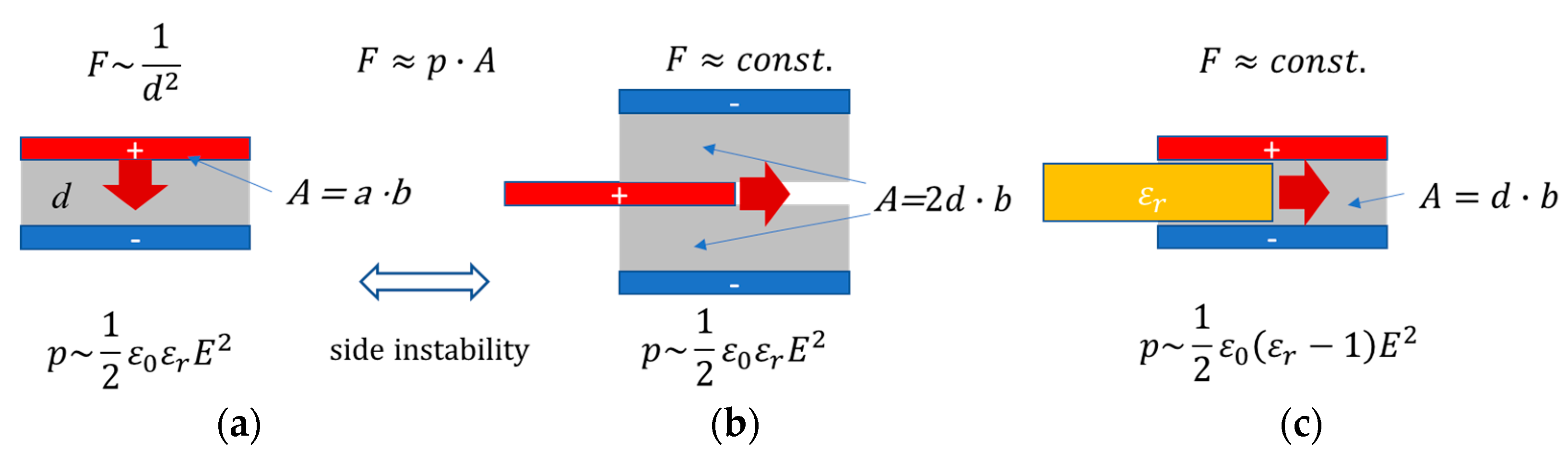
2.1. Electrostatic Vertical Attracting and Tangential Forces

With the rise in the use of microactuators, the importance of electrostatic forces has become apparent. The “small” gaps in microsystems, in combination with the Paschen effect, allows for the use of electrical field strengths far above the values achievable in macroscopic systems before causing an electrical breakdown.
A limiting factor for long-stroke electrostatic actuators is the small level of force, which decreases rapidly as the gap between the actuated electrodes increases. Electrostatic forces are proportional to the (already quite small) constant of vacuum permittivity; ε 0 = 8.854 × 10 12 A s V m . The material-related relative permittivity ε r is almost 1 for gaps filled with gases, and typically <100 for common polar liquids (about 80 for water). Therefore, electrostatic actuators play no role in macroscopic actuation, and their being considered “long-stroke” depends on the point of view. For this paper, we have defined “Long-stroke” as meaning approximately 100 μm.
The electrostatic force is usually calculated from the directional derivative F = W C of the energy stored in a capacitor:
W = 1 2 C U 2
Generally, common electrostatic actuators use either the vertical attracting force or the tangential force, both being always present between the plates of a capacitor. With the vertical attracting force, the parallel-plate actuators achieve stable displacements up to 1/3 of the electrode distance, as shown in Figure 1a. The displacement of the comb-drive actuators is based on the tangential force caused between two not fully overlapping plates (Figure 1b). Unfortunately, both forces do not exhibit a linear force–deflection graph that pairs well with linear guiding springs.
A normalized expression with respect to the electrode area is introduced here, comparable to an “electrostatic pressure” p e that is also commonly used in dielectric elastomer actuators [23]. Additionally, the voltage is replaced by the local electrostatic field E = U d , where d is the shortest relevant distance between the electrodes, as fringing fields are initially neglected here.
With b being the out-of-plane width, this results in:
  • Vertical parallel-plate actuation:
F v = 1 2 ε 0 ε r A d 2 U 2 , n o r m a l i z e d : p e , v ~ 1 2 ε 0 ε r E 2
  • Tangential parallel-plate comb actuation:
F t = ε 0 ε r b d U 2 , n o r m a l i z e d : p e , t ~ 1 2 ε 0 ε r E 2
  • The relevant normalization area is given using the gap area in the direction of movement: A = b · 2 d , and for standard “dry” actuators with gas-filled gap d, the dielectric constant ε r is almost 1. As the area to which the pressure applies does not change with actuation, the resulting force is constant as long as both plates do not fully overlap. Additionally, a tangential actuation of dielectrics, particularly liquids, can be approximated in a similar way. In this case, any dielectric (dielectric constant ε r > 1 ) is drawn into an air-filled ( ε r 1 ) capacitor (see Figure 1c). Here, the calculation of the electrostatic pressure results in a quite similar formula: p e , l i q u i d 1 2 ε 0 ε r 1 E 2 ; note that this electrostatic pressure is usually much larger due to the factor ε r 1 and will be used for the springless long-stroke actuation.
  • The electrostatic pressure is proportional to E 2 .

2.2. Guiding Mechanisms for Long-Stroke Actuators

Two important parameters for the design of cooperative long-stroke microactuators are the required load and the force at the maximum stroke. Whereas solutions for large forces at small stroke scales are well known, a long stroke is much more difficult, as most of the microactuators make use of rigid springs and the force of the spring increases with the size of the stroke. Furthermore, to guarantee a translational displacement, the springs have to exhibit anisotropic spring constants. However, the stiffness’ in all other directions directly influences the achievable stroke of the actuator system. Guiding springs with optimized designs should provide a low spring constant in the actuated direction, but a strong guidance both in the other spatial directions and with respect to parasitic rotational movements. Therefore, the reaction force Fx and stiffness cx in the direction of deflection must be low, but the stiffnesses in all other directions need to be much higher. The selectivity S is a suitable parameter for this demand:
S = c i , i x c x
A high selectivity is naturally provided with clamped beams [24], as shown in Figure 2a. However, actuators guided by clamped beams achieve only small displacements due to the strongly non-linear force–displacement characteristic (FDC) increasing sharply with displacement [25]. Figure 2b shows serpentine springs (also called folded or meander springs), which exhibit a constant low spring stiffness in deflection direction, and are therefore often used for guiding electrostatic actuators. Serpentine springs allow deflection in one direction, only. Due to their sharply decreasing selectivity in line with deflection, the serpentine springs tend to exhibit significant lateral instability when guiding long-stroke actuators [26]. Even the smallest unbalances during fabrication can cause a rotation due to uncompensated torque in the cantilevers.
Further common spring geometries for in-plane deflection include the M-shaped springs with non-linear, asymmetric force–displacement characteristics [27]. An advanced geometry is provided for both triangular and sinusoidal springs [28]. The triangular springs (Figure 2c) have an almost linear force–displacement characteristic with a high selectivity, achieving large deflections in both positive and negative x-directions. These springs are highly variable in appearance, as the number of spring segments (nB), the length L of each beam, and the inclination angle α can be varied. The triangular springs can be transferred to sinusoidal springs. The sinusoidal shape reduces the local stress appearing at the kink from one beam to the next and thus reduces the risk of rupture [28].
Figure 3 compares the cx- and cy- stiffness of a triangular and a serpentine spring. Both springs exhibit the same stiffness and selectivity in idle mode. With increasing stroke, the stiffness cx quadratically increases for the triangular spring, while it remains constant for the serpentine spring. The stiffness cy shows a sharp drop for the serpentine spring, while it remains almost constant for the triangular spring. The selectivity S resulting from (4) decreases much faster for the serpentine spring than for the triangular spring.
Figure 3c shows the force reaction of both springs. The spring force Fx of a triangular spring in the x-direction has been approximated for an even number of beam elements nB [28]:
F x , tri = 12 A E I Z L 1 + n B A L 2 1 + n B 2 cos α 2 + 12 I Z sin α 2 · x + 144 A E I Z 1 + n B 5 L L p r o j n B 2 48 I Z 1 + n B 2 cos α 2 + A L 2 1 8 n B + 4 n B 2 sin α 2 · x 3 , n B ϵ { 2 , 4 , . . . }
Here, Lproj is the projected length of the triangular spring, IZ the second moment of area, E the Young’s modulus and the area A is the product of the beam length L and the substrate depth. From (5), the force Fx,tri depends on the displacement via the factors x and x3. Consequently, the force–displacement characteristic has both a linear and a non-linear component. According to [28], the linear part of the force Fx,tri,linear is described as
F x , t r i , l i n e a r = x · n B 1 3 L 3 c o s 2 α 12 E I z + n B 1 L sin 2 α E A 1 , n B ϵ 2 , 4 ,
The linearity of the triangular spring increases with increasing angle of inclination α. With an increasing number of beams, the linearity of the spring decreases; however, the selectivity increases in the ratio S ~ n B 2 [28]. L5% describes the region in which the force–displacement characteristic deviates by a maximum of 5% from a linear curve. L5% is presented in Figure 3c and approximately described as follows [28]:
L 5 % 5 % · 5 L 2 c o s 2 α 12 · 48 I z n B 1 2 + A L 2 1 8 n B + 4 n B 2 t a n 2 α A L 2 n B 1 2 + 12 I z t a n 2 α , n B ϵ 2 , 4 ,
In addition to the above springs, bi-stable curved springs (with their negative spring rate [29,30], as shown in Figure 4) should be highlighted for use in electrostatic actuation. These springs can achieve high deflections, but their force–displacement characteristic is nonlinear. These guiding mechanisms can even achieve constant force responses [31,32]. Springs that directly apply a constant force are space saving, and a simple alternative to the complex force–feedback systems that are often used to control the actuator force [33,34]. Boudaoud et al. [35] used a comb-drive actuator guided by bending beams clamped on both sides, connected to a complex capacitive force sensor. Such constant force mechanisms (CFM) achieve a constant output force at specific deflection levels by applying an external force, such as a voltage [36,37]. In the constant force region, the stiffness of such springs is ideally 0 N/m. A constant force can also be achieved by means of, e.g., buckling a spring mechanism [37,38,39], which results in increased deflections and reduced switching voltages [40].
The electrode shape can also be used to generate constant forces or to realize large displacements. There are several approaches for special comb drive finger designs, such as those in [25,41]. Engelen et al. presented a finger shape, providing a constant available force that is up to 1.8 times larger than using a straight finger design, and reducing the actuator size [42]. By varying the shape and length of the comb-drive fingers, the comb-drive actuators can achieve larger displacements, as demonstrated by Grade et al. in [1]. In [43] it is shown that comb drives with variable-gap profiles can be designed to deliver specific driving force profiles.

2.3. Electrostatic Comb Drives for Long-Stroke Actuation

Tangential electrodes appear to be ideal for long-stroke actuators; their force does not depend on the geometry in direction of movement as long as the two electrodes do not overlap completely. The total force can easily be increased using comb-drive actuators with a reasonable number of fingers, while the parallel-plate forces simply cancel out due to their opposed direction. A decrease in the lateral distance d increases the force, allowing for a dense comb array and, thus, higher forces. Theoretically, the stroke seems to be almost “infinite” as long as the two electrodes completely overlap. The most critical limiting effect results from the increasing overlap and thus the resulting parasitic vertical forces.
However, as a closer view shows, this is an incomplete picture of events. The use of comb-drive actuators is in fact limited by two main properties: On one hand, the electrostatic force stays constant over the complete travel range while the retracting force of the springs increases with the stroke, which results in an increased driving voltage. On the other hand, the area at which the parallel-plate forces are acting increases with a larger overlap. For comb-drives, where the tangential derivative is important, this seems to be less critical. Unfortunately, the well-investigated side instability depends on 1 d 2 and any unavoidable small asymmetries from fabrication cause a deflection to one of the two electrodes, which in turn leads to the moving part sticking to their current position [7,26]. The side-instability is significantly influenced by the guiding spring. Legtenberg et al. [26] have demonstrated that serpentine springs work well for long strokes thanks to their low stiffness cx. The characteristic displacement of the voltage-dependent displacement is shown in Figure 5. Lateral pull-in due to lateral instability occurs in Figure 5c. However, the stiffness of serpentine springs in off-axis direction decreases with increasing deflection, as shown in a long-stroke system (Figure 6a), causing lateral instability in the comb-drive actuator.
Within the stable region of the comb-drive actuator, the vertical forces on the left and right of the electrodes cancel out:
F e l = n ε 0 t F x + x 0 2 d + y 2 U 2 n ε 0 t F x + x 0 2 d + y 2 U 2
The unstable electrode deflection starts as soon as the first derivative of the electrostatic force orthogonal to the deflection direction exceeds the stiffness of the spring cy. The opposing forces of the electrodes no longer cancel out, meaning that the rotor approaches the stator, blocking further deflection in the x-direction:
c y > 2 n ε 0 t F x + x 0 d 3 U 2
The voltage USI at which the lateral instability occurs depends on the stiffness cx and cy and thus the selectivity S, as well as on the actuator geometry:
U S I 2 = d 2 c x 2 ε 0 t F n 2 c y c x + x 0 2 d 2 x 0 d = d 2 c x 2 ε 0 t F n 2 S + x 0 2 d 2 x 0 d
The maximum stable displacement xSI depends on the electrode spacing, the initial overlap, and the selectivity of the spring. For a spring with very high selectivity ( c y c x ), the maximum deflection reaches:
x S I = d c y 2 c x x 0 2 = d 1 2 S x 0 2
According to (11), the deflection increases in line with increasing spring selectivity S [26]. Therefore, the springs presented in Figure 3 are suitable to fulfil this requirement. Figure 6a shows a microscopic image of a fabricated actuator with triangular springs. Figure 6b shows the voltage-dependent displacement of two comb-drives: The deflection of the actuator with serpentine springs was approximately quadratic to the applied voltage (x ~ U2), the maximum deflection was limited to 103 µm and 70 V whereas the actuator with triangular springs achieved a maximum deflection of 145 µm at 104 V, an increase of more than 40%. Furthermore, the voltage-displacement characteristic remained almost linear.

2.4. Large Displacements Based on Parallel-Plate Actuators

2.4.1. Electrostatic Parallel-Plate Actuators

Comb-drive actuators usually exhibit a low force, and their displacement requires an active position control. In contrast, parallel-plate actuators allow for a high reaction force. However, the displacement of parallel-plate actuators is limited by the electrode distance d0, as shown in Figure 7a. With respect to long-stroke actuation, the attractive force between two parallel-plate electrodes seems to be less suitable, as d 2 usually needs to be much smaller than the area of the electrodes. This would result in an increased size of A d 2 for a reasonable force at d = d 0 , but approaching an infinite force for a vanishing gap d 0 .
The characteristic force–displacement curve of a parallel-plate actuator operating against a linear spring is outlined in Figure 7b. It does not allow control of the position across the whole range of the gap d 0 . As the electrodes move closer together (with x = d 0 d ), the electrostatic force increases with F ~ 1 d 0 d 2 with lim d d 0 1 d 0 d 2 = , theoretically approaching an infinitely high electrostatic force.
Assuming a rotor guided by a simple linear spring would result in a non-linear behavior, the restoring mechanical force FS counteracts the electrostatic force Fel between the electrodes. At a displacement of d = 1 3 d 0 , the mechanical spring force can no longer balance the steeply increasing electrostatic force; at this point, F e l = F S , F e l d = F S d applies. Pull-in occurs, the movable electrode is abruptly pulled towards the counter electrode, d 0 d 0 , as depicted in Figure 7c. With A being the surface and c the linear spring constant, the pull-in voltage Upull-in is simply identified as follows:
U p u l l i n 8 c d 0 3 27 ε 0 ε r A
Despite this, the pull-in condition allows for a very efficient low-voltage high-force actuator by means of the cascaded stiffness of the springs, as demonstrated in [11]; it can thus achieve a stable “digital” behavior (undeflected/fully deflected at U = 0/U = Upull-in). For this purpose, the electrodes are electrically insulated (e.g., using SiO2) to prevent a short when the electrodes contact. Here, the bending-plate actuators are combined with triangular/serpentine springs (see Section 2.2) as shown in Figure 8. As known from [44], the stator features electrodes which connect to a rigid cantilever, and the rotor features thin electrodes which connect to the actuated platform, guided by flexible springs. The cascaded stiffness is part of the specific design, as the thinnest cantilevers bend at the start of the process, then becoming more and more attracted, and finally end up fixed to the stiffer cantilevers.
The switching speed is limited by squeeze film damping, as the air within the gap between the electrodes has to be squeezed out; a process that is accelerated by higher forces at higher voltages [45]. During pull-in, the stiff cantilever also slightly bends the distance b towards the electrodes, which reduces the displacement of the bending-plate actuator xa (Figure 8b). Therefore, it is not only the spring stiffness cs, but also the cascaded cantilever thicknesses that strongly influences the pull-in voltage [44]. For the actuator shown in Figure 8, the pull-in voltage is described as follows [11]:
U p u l l i n 2 E S i C 3 d 0 3 27 ε 0 ε r L 4
Using insulating layers prevents an electrical short during actuation. The high field strengths across thin electrical insulation bear the risk of self-charging of the dielectric, which can result in a permanent static charge. The worst-case scenario here would be that the actuator is unable to release after switching off the voltage. Replacing the DC voltage with an AC voltage reduces the risk of permanent charging but increases the power consumption as a frequency-dependent AC current is required to charge and discharge the electrodes. It has to be noted that the AC frequency needs to be significantly higher than the mechanical resonance of the system to prevent a parasitic resonant excitation of the mechanical system. For DC actuation, the required permanent electrical power is almost close to zero after charging only once. Alternatively, an electrical short can be prevented using local spacers or pull-down resistors [12].

2.4.2. Electrostatic Parallel-Plate Actuators with Multiple Stable Steps

To achieve long-stroke actuation, systems based on cascaded actuators are our objective. An effective way to achieve such systems is to stack bending-plate actuators with stepwise increasing gaps and connecting springs ci [12,44,46]. From the initial position (Figure 9a), the actuation starts by applying a voltage to the first actuator a1, after which the system moves for xactuator,1 and the gap at actuator a2 decreases. By additionally applying a voltage to the second actuator a2, the system displaces again, now for the distance xactuator,2. When all three actuators a1, a2 and a3 are activated, the system reaches xactuator,3. The required voltage does not increase; a1–a3 operate at the same pull-in voltage.
For large displacements at low voltages, the stiffnesses of the guiding cg and connecting springs ci are crucial parameters. The influence of the spring stiffness on the total system displacement xactuator,i depending on the activated actuators ai [12] is described as follows:
x a c t u a t o r , i = x i c g · n i c i + 1 c g , f ü r   i n
For this study, an actuator in line with Figure 9 was realized and evaluated. The actuators were sequentially activated. Figure 10 shows the resulting displacement due to the step-by-step activation of the actuators. The red dots mark the actuators with an applied voltage. In [12], we present the evaluated experimental displacements as well as the dynamic switching behavior, showing eigenfrequencies between 90 Hz (avg. cg = 2.90 N/m) and 139 Hz (avg. cg = 0.17 N/m), depending on the stiffness of the guiding spring. A video of the stepwise displacing actuator is available at https://etit.ruhr-uni-bochum.de/mst/forschung/projekte/marie/ accessed on 28 March 2023.

2.4.3. Digital-to-Analog Converting Actuators (DAC)

For the step-like long-stroke actuators presented in Section 2.4.2, the step count was equal to the number of actuators, resulting in a complex system wiring. In this section, we present digital-to-analog converters (DACs) where the number of addressable positions increases exponentially with the number of [47]. A true mechanical DAC converts a binary input code into an analog mechanical output displacement proportional to the analog value of the input code. Thus, the control and wiring of true DACs is significantly less complex than for conventional actuators (for N bit N actuators, as compared to 2N actuators). In-plane microelectromechanical DACs based on electrostatic actuators have been demonstrated; Toshiyoshi et al. [48] and Sarajlic et al. [47] presented DACs based on comb-drive actuators, and achieved maximum binary encoded displacements of up to 5.8 µm at 150 V and 8.6 µm at 45 V, respectively.
The DAC for long-stroke operation, shown in Figure 11a, consists of three ‘bits’ [49,50,51]. Each ‘bit’ features guiding springs cgi, connecting springs cci, and two actuators ( a i , d o w n and a i , u p ) . Here, a i , u p / d o w n represents a Boolean variable associated to the ith slider of the DAC, which can be either set to a value of 1, if a voltage is applied, or 0 for a non-active actuator. Therefore, the slider is either displaced upwards, when activating the upper actuator ( a i , u p = 1 and a i , d o w n = 0 , Figure 11d), or downwards, when activating the lower actuator ( a i , u p = 0 and a i , d o w n = 1 , Figure 11b). In our first attempt, the two actuators of each bit were linked by a rigid slider, so each actuator can be individually set in an up or down position, resulting in a mere 23 = 8 positions. In our second approach, each ‘bit’ could address four different states: 0–0, 1–0, 0–1 and 1–1. In Figure 11d, the upwards actuator a i , u p has been activated and position 1–0 is thus shown. In Figure 11b, position 0–1 is depicted by activating the downwards actuator a i , d o w n . When activating both actuators simultaneously ( a i , u p = a i , d o w n = 1 ), the intermediate position 1–1 is achieved, as shown in Figure 11c. In position 1–0, the bit achieves its largest displacement, in position 1–1 an intermediate displacement and in position 0–1 the smallest displacement [52]. Position 0–0 is an undefined state not suitable for actuation.
With N = 3 connected bits, the resolution of the DAC subsequently increased from 23 = 8 to 33 ≙ 27, as presented in Figure 12a. Bit 0 proved to be the least significant bit (LSB). The displacement of the LSB resulted in a partial deformation of the connecting springs c c 1 and c c 2 . As the output of the most significant bit (MSB) is not connected to a further spring, the entire MSB displacement resulted in the DAC displacement. Therefore, the impact of each bit on the final system displacement appears to add up along the chain of the connecting springs. The DAC resolution can be enlarged by adding more sliders, such that a combination of, e.g., four or five sliders would result in a resolution of 34 ≙ 81 or 35 ≙ 243, respectively. By adding more bits to the DAC, the overall DAC displacement xDAC increased, too. As the DAC is a mechanically connected system, the stiffness of the springs and actuators is important for the linearity of the actuation and a large stroke, which has also been investigated by Sarajlic et al. [47]. The DAC stiffness is important for large displacements when connecting the DAC to a mechanical leverage, which results in an increased DAC displacement (experimentally, up to 234.5 µm, as shown in [53]).
A video of the mechanical DAC is available at https://etit.ruhr-uni-bochum.de/mst/forschung/projekte/marie/, accessed on 28 March 2023.

3. Springless Long Stroke/Infinite Stroke Actuators

3.1. Actuator Concept

As demonstrated before, a limiting factor for long stroke lengths is the solid spring. With optimized designs, the range can be extended, but for displacements in the mm or even cm range, solutions with non-rigid bearings are better suited. A promising alternative is the use of liquid bearings: surface tension in droplets in the micro-range provides a roller bearing and a virtual spring between two surfaces at the same time, although several constraints have to be fulfilled. The calculation of the spring constant is different from rigid cantilever systems, and the properties of the surfaces as well as of the liquid and their mutual interaction all have an important impact. Nonetheless, the actuation of droplets by applying electrostatic fields is a well-known approach (e.g., in digital microfluidics [53,54], where the movement and manipulation of single droplets is a common application). Especially in medicine and biotechnological applications, microfluidics continues to attract more and more attention. Digital microfluidics (DMF) in particular enables the realization of lab-on-a-chip applications [55]. Unlike in conventional microfluidics, individual droplets are manipulated in DMF. This technology allows for transport, separation, as well as improved mixing and merging processes of the smallest liquid volumes [53]. In combination with other analytical tools, for example, new types of point-of-car platforms can be developed [56]. In addition to the very small volumes that can be processed, the low power consumption and the lack of need for valves and pumps are further advantages of DMF [57].
For cooperative long-stroke actuators, the droplets become part of a liquid roller bearing or “wheel”, as well as of the actuator itself: three or more droplets are tethered to a moving platform, e.g., a small substrate, while the actuation is induced using the on-chip travel path.
Electrowetting on Dielectrics (EWOD) is probably the best-known method of actuation in DMF systems [56,57]. EWOD describes the behavior of a conductive or polar liquid on an electrode isolated using a dielectric when a potential difference is applied between them; basically, the fluid is electrically connected. The applied voltage results in a change in the contact angle between the substrate and the drop, which can be described using the Young–Lippmann equation:
cos θ = cos θ 0 + ε 0 ε d 2 d γ l v U 2
Here, θ 0 is the contact angle between liquid and solid surface at U = 0; ε 0 is the permittivity of vacuum, and ε d is the permittivity of the dielectric layer; d is the thickness of the dielectric, γ l v is the surface tension of the liquid, and U is the applied voltage.
The electrostatic force acting on the droplet can be derived from the change in the energy within the capacitors, or more generally, using the Maxwell stress tensor, see [58,59].
At microscale level, surface effects such as surface tension dominate, such that drops can also be used as liquid bearings in microsystems. In [60], a MEMS micromotor was realized based on such a liquid bearing. In [61], a liquid motor was presented using EWOD, with a droplet serving as a liquid bearing. A further application of EWOD with liquid bearings is shown in [62], wherein four drops carried a micromirror. Changing the contact angle between the drop and the support tilted the mirror, but the mirror was not moved ‘in plane’.
The system for long-stroke actuation presented in this study used a combination of lateral droplet transport and the properties of microdroplets as liquid bearings. It consisted of a movable platform resting on four droplets. There were no solid springs connecting the platform with the substrate. The platform was instead moved laterally on a long scale by applying electric fields between planar electrode arrays on the substrate, whereby the drop itself was not in direct contact with an electrode.
Two different shapes of electrode arrays consisting of interdigital electrodes have been investigated so far; one had trapezoidal boarders, and the other one had sine shaped boarders, as shown in Figure 13. The interdigital structures ensured an increased contact line between the droplet and the neighboring electrode. The gap between the two electrodes was set to be about 20 µm. This system was designed for a drop with a contact area radius of 600 µm, corresponding to a drop of, e.g., DI water with a volume of 1.2 µL, and a contact angle of 120° in air. This demonstrator used DI water, but other polar fluids are also suitable, e.g., low-vapor pressure polar fluids such as ethylene glycol ( ε r = 37) and glycerol carbonate ( ε r = 110).
The electrodes were realized using lithographically structured aluminum on silicon, with a 2 µm thermal SiO2 layer to insulate the electrodes. The dielectric layer consisted of 110 nm Al2O3, deposited using atomic layer deposition (ALD). To achieve a reliable hydrophobic surface with a contact angle >90°, a 1% fluoropolymer solution (FluoroPel PFC1601V-FS) was applied by means of spin coating (Figure 14).
The moving platform was a 220 µm thick silicon chip, likewise coated with fluoropolymer. The hydrophobic coating was locally removed from the contact areas where the droplets were to be attached as bearings.

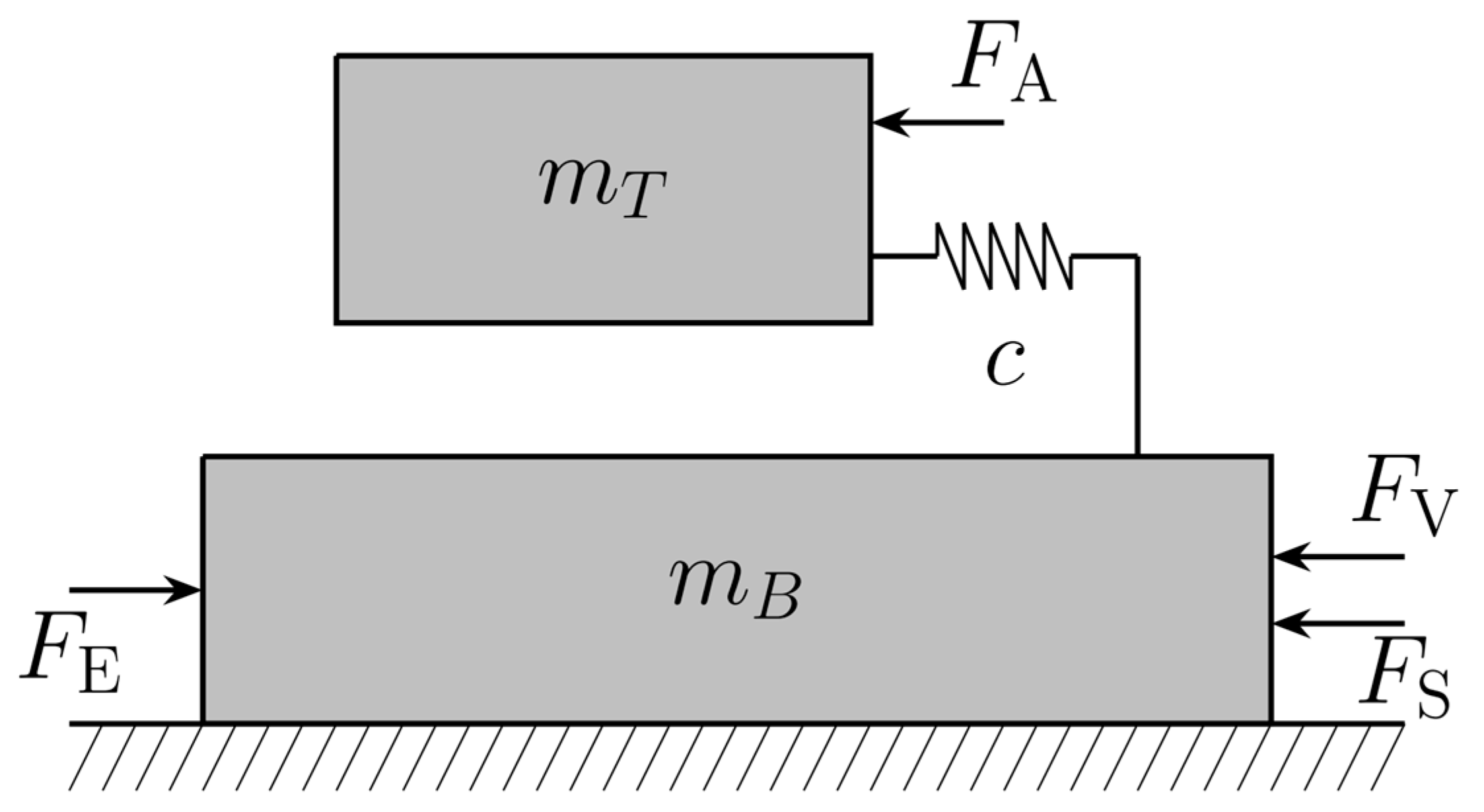
3.2. System Modelling

For an approximated model describing the dynamic behavior of the long-stroke actuator for precise motion control, the system is decomposed into the four droplet bearings suspending the actuator platform. The elastic behavior of the droplets is represented by the spring constant c. A single droplet can be described using the mechanical analogy depicted in Figure 15.
The platform mass m T was connected to the bottom mass m B , corresponding to the droplet mass, by a linear spring with the stiffness c . In combination with the quadratic air friction force F A , this enabled the emulation of the droplets ringing behavior. The air friction within the model is given as follows:
F A = sign ρ ˙ d T ρ ˙ 2
where ρ ˙ denotes the velocity of the top mass and d T denotes the friction coefficient. The combination of the nonlinear friction force F S and the linear friction force F V reflects the interaction at the interface between droplet and chip. This allowed us to incorporate the adhesion of the droplet, inhibiting the movement below a certain actuation voltage in the model. These friction forces are modelled as
F s = H 0 e p ˙ 2 v T 2 atan ( α p ˙ )
F V = d 2 p ˙
where p ˙ denotes the velocity of the bottom mass and H 0 and v T are calibration coefficients to the behavior of the maximum (force) of the nonlinear friction force F S . The calibration coefficient α allowed us to adjust the gradient of F S for a non-moving droplet. The electrostatic force F E can be derived by means of differentiating the electrostatic energy of the droplet when applying a voltage U, with respect to the position of the droplets base, modelled as the position of the bottom mass m B , as discussed before. From the FEM-simulation, we derived electrostatic forces up to 9.85 µN for a single droplet.
Using the aforementioned forces, a model for the droplet behavior can be deduced, including unknown parameters such as the spring stiffness c . Such parameters can only be identified using experimental data. The simulation result with these identified parameters for a single droplet (alongside of the used experimental data, as well as the error e between simulation and measurement) are depicted in Figure 16.
The whole actuator was considered as a platform, inextricably connected to the four suspending droplets. To derive a dynamic model, the platform with side length 2a was attached at each corner to the four corresponding top masses of the mechanical analogy depicted in Figure 15. Taking only the translational degree of freedom along the electrode array into account, the governing differential equations can be derived using the Lagrangian formalism. Considering the positions p i of the respective droplet base and ρ the position of the platform as generalized coordinates, and the friction and electrostatic forces as non-conservative forces of a Lagrangian formalism, a set of governing differential equations can be derived. Reformulating these equations using the state vector
x = p 1   p 1 ˙   p 2   p 2 ˙   p 3   p 3 ˙   p 4   p 4 ˙   ρ   ρ ˙ T
results in a system of first-order differential equations typically used for simulation or control applications:
x ˙ = x 2 1 m B , 1 F E , 1 x 1 , V 1 F S , 1 x 2 d 1 x 2 k 1 x 1 + a x 9 x 4 1 m B , 2 F E , 2 x 3 , V 2 F S , 2 x 4 d 2 x 4 k 2 x 3 + a x 9 x 6 1 m B , 3 F E , 3 x 5 , V 3 F S , 3 x 6 d 3 x 6 k 3 x 5 + a x 9 x 8 1 m B , 4 F E , 4 x 7 , V 4 F S , 4 x 8 d 4 x 8 k 4 x 7 + a x 9 x 10 k 1 x 1 + a x 9 + k 2 x 3 + a x 9 + k 3 x 5 a x 9 + k 4 x 7 a x 9 sign x 10 d ρ x 10 2 m P + m T , 1 + m T , 2 + m T , 3 + m T , 4
where the friction coefficient d ρ incorporates the friction of the platform and all d T , i . To reflect the behavior of an existing actuator, the parameters of the system model (20) had to be determined. This was achieved using a system identification approach, as described for a single droplet in [63].

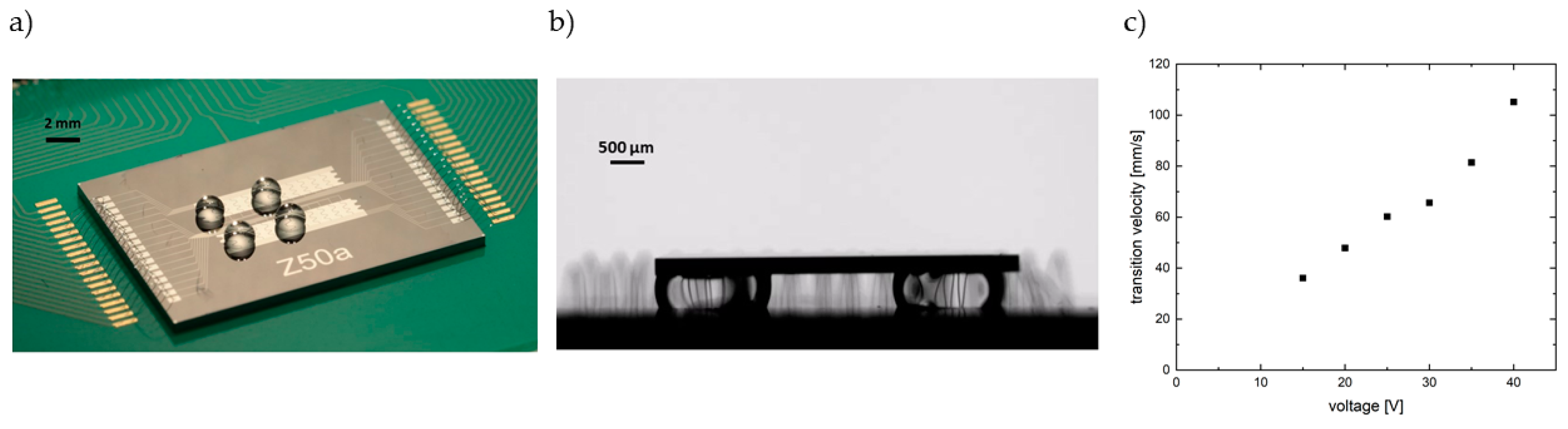
3.3. Experimental Results

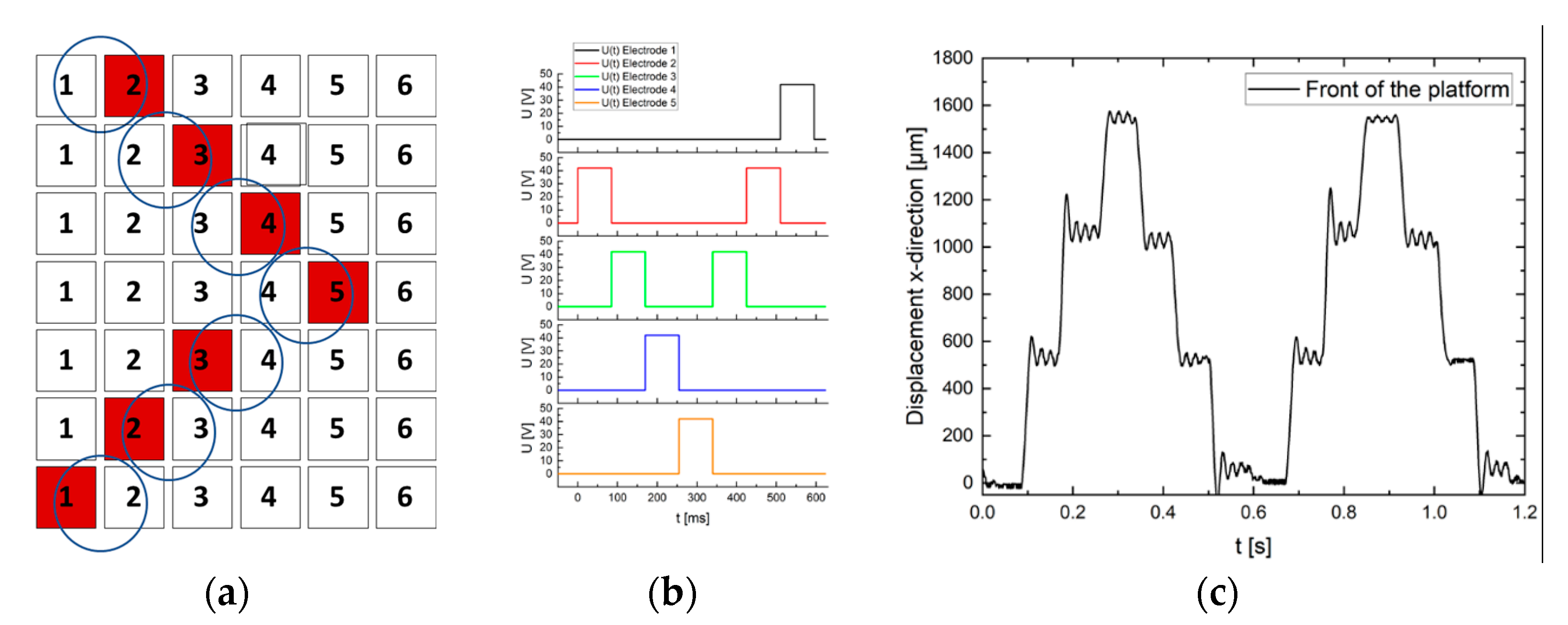
3.3.1. Coordinated Droplet Actuation for Moving Platforms

The droplets were positioned on the electrodes by means of applying a voltage on the required electrodes. Figure 17a shows the four liquid bearings in their initial position. To ensure a smooth movement of the platform, all drops needed to be actuated synchronously. For this purpose, the neighboring electrode in front of the drop was switched on, so that the electrostatic force pulled the drop into the field. In this configuration, reproduceable droplet movements can be achieved at voltages as low as U = 20 V [64].
Figure 17b shows a cross-sectional view of the platform on four droplets. The drops were slightly deformed by the weight of the platform, resulting in a modified contact surface.
A stable movement with the payload of the platform could be achieved at 40 V. A video of the moving platform is available at https://etit.ruhr-uni-bochum.de/mst/forschung/projekte/kommma-raeumliche-aktorik/, accessed on 28 March 2023. The speed of the moving platform depended strongly on the switching period of the electrodes. For a switching time of 85 ms at 42 V, the speed v of the platform was approximately 5.5 mm/s. The demonstrator platform allowed a maximum distance of 1500 µm (Figure 18). Theoretically, the stroke of this actuator system is infinite and determined only by the number of control electrodes.
Figure 18. (a) Actuation scheme for every liquid bearing. Five control electrodes were switched on (red) sequentially for 85 ms at 42 V;(b) voltage input timing sequence.. First period guaranteed a stable initial position of the moving platform. (c) Platform displacement in x-direction. Displacement was measured at the front side of the platform (cf. Figure 19).
Actuators 12 00150 g018

3.3.2. Multistability

Unfortunately, the described scheme exhibited a disadvantage: if no voltages are applied, the droplets on the non-wetting surface tend to roll off the electrode area if there is any kind of tilt of the electrode substrate. Therefore, it is necessary to “fix” the droplets in their positions. This also allows us to achieve a multi-stable behavior. Such a multi-stable step-like behavior of the platform system was achieved using mechanical barriers introduced into the system in places where the droplet was intended to stick. In a first attempt, photoresist piles were created on the electrode structures (Figure 20). Four of these trapezoidal photoresist structures featured a barrier to hold the droplet in a stable position even when no voltage is applied, or if the chip is tilted.
Here, the dielectric Al2O3-layer had a reduced thickness of 60 nm. The photoresist is applied on this dielectric, featuring a height of approx. 9 µm. Subsequently, the completed structure is hydrophobically coated with FluoroPel PFC1601V-FS by means of spin coating. The hydrophobic state is shown in Figure 21.
Figure 22 shows four droplets without load that are moved synchronously by means of applying 25 V to the control electrodes. The increased voltage (compared to 20 V in [64]) is needed to overcome the additional barriers. Figure 23 shows the setup with barriers, four liquid bearings and the platform on top. In this case, the platform consisted of a 100 µm thick glass substrate, likewise coated with FluoroPel, and the droplets stuck locally to the platform. Again, two electrodes had to be activated simultaneously to move the platform. A voltage of 35 V was applied to the activated electrodes for 500 ms. The platform was able to move step-by-step. The forward movement is shown in Figure 23. The use of mechanical barriers to create multi-stable states for the drop-based long-stroke actuator was thus successfully demonstrated. These energy states can easily be adjusted using the height and shape of the barriers.

4. Summary and Outlook

This contribution provided an overview of non-inchworm long-stroke actuators and presented some recent improvements based on evolved spring concepts for common electrostatic actuator systems and a spring-free system with liquid bearings. Such systems have allowed us to integrate step-like actuators with an theoretically infinite stroke length. It should be noted that all systems require actuation voltages <100 V. This voltage range can easily be supplied using surplus up-conversion from low voltages. As almost no current is needed, the power consumptions of these systems is low, and high-impedance voltage sources create no safety risk. Our own unpublished work has shown that such actuators can be powered using RFID or NFC systems.
Electrostatic actuation for long-stroke application can facilitate yet further improvements. Such solutions strongly depend on the constraints of the system environment, and requires both careful design and a selection of the spring-actuator system that is far more meticulous than the comparatively simple basic principles of electrostatic force effects.

Author Contributions

Conceptualization, M.H.; methodology, L.S., P.C. and A.K.; software, L.S., P.C. and A.K.; validation, M.H., C.A., L.S., P.C. and A.K.; formal analysis, L.S., P.C. and A.K.; investigation, L.S., P.C. and A.K.; resources, M.H. and C.A.; data curation, M.H., C.A., L.S., P.C. and A.K.; writing—original draft preparation, M.H., L.S., P.C. and A.K.; writing—review and editing, M.H. and L.S.; visualization, L.S., P.C. and A.K.; supervision, M.H. and C.A.; project administration, M.H. and C.A.; funding acquisition, M.H. and C.A. All authors have read and agreed to the published version of the manuscript.

Funding

Funded by the Deutsche Forschungsgemeinschaft (DFG, German Research Foundation) –Project-ID 287022738—Collaborative Research Centre TRR 196—Mobile Material Characterization and Localization by Electromagnetic Sensing, C12 and Priority Program SPP 2206—KOMMMA—Cooperative Multistage Multistable Microactuator Systems (HO 2284/14-1 and AM 120/9-1).

Data Availability Statement

The data can be provided upon reasonable request.

Acknowledgments

The authors thank the Center for Interface Dominated High Performance Materials (ZGH), Ruhr University Bochum (RUB), for the opportunity to use deep etching equipment. The ALD layers have been fabricated within the BMBF-ForLab-Bochum-PICT2DES-grant number: 16ES0941 and in cooperation with David Zanders, Inorganic Materials Chemistry Group, RUB.

Conflicts of Interest

The authors declare no conflict of interest.

References

  1. Grade, J.; Jerman, H.; Kenny, T. Design of large deflection electrostatic actuators. J. Microelectromechanical Syst. 2003, 12, 335–343. [Google Scholar] [CrossRef]
  2. Jerman, J.H.; Grade, J.D.; Drak, J.D. Electrostatic Microactuator and Method for Use Thereof. U.S. Patent 5,998,906, 7 December 1999. [Google Scholar]
  3. Zhou, G.; Dowd, P. Tilted folded-beam suspension for extending the stable travel range of comb-drive actuators. J. Micromechanics Microengineering 2002, 13, 178–183. [Google Scholar] [CrossRef]
  4. Chen, C.; Lee, C. Design and modeling for comb drive actuator with enlarged static displacement. Sens. Actuators A Phys. 2004, 115, 530–539. [Google Scholar] [CrossRef]
  5. Xue, G.; Toda, M.; Li, X.; Wang, X.; Ono, T. Assembled Comb-Drive XYZ-Microstage With Large Displacements and Low Crosstalk for Scanning Force Microscopy. J. Microelectromechanical Syst. 2021, 31, 54–62. [Google Scholar] [CrossRef]
  6. Olfatnia, M.; Sood, S.; Gorman, J.J.; Awtar, S. Large Stroke Electrostatic Comb-Drive Actuators Enabled by a Novel Flexure Mechanism. J. Microelectromechanical Syst. 2012, 22, 483–494. [Google Scholar] [CrossRef]
  7. Zhang, W.-M.; Yan, H.; Peng, Z.-K.; Meng, G. Electrostatic pull-in instability in MEMS/NEMS: A review. Sens. Actuators A Phys. 2014, 214, 187–218. [Google Scholar] [CrossRef]
  8. Legtenberg, R.; Gilbert, J.; Senturia, S.D.; Elwenspoek, M. Electrostatic curved electrode actuators. J. Microelectromechanical Syst. 1997, 6, 257–265. [Google Scholar] [CrossRef] [Green Version]
  9. Preetham, B.S.; Lake, M.A.; Hoelzle, D.J. A curved electrode electrostatic actuator designed for large displacement and force in an underwater environment. J. Micromechanics Microengineering 2017, 27, 095009. [Google Scholar] [CrossRef] [Green Version]
  10. Preetham, B.S.; Mangels, J.A. Performance evaluation of a curved electrode actuator fabricated without gold/chromium conductive layers. Microsyst Technol 2018, 24, 3479–3485. [Google Scholar]
  11. Hoffmann, M.; Nüsse, D.; Voges, E. Electrostatic parallel-plate actuators with large deflections for use in optical moving-fibre switches. J. Micromechanics Microengineering 2001, 11, 323–328. [Google Scholar] [CrossRef]
  12. Schmitt, L.; Hoffmann, M. Large Stepwise Discrete Microsystem Displacements Based on Electrostatic Bending Plate Actuation. Actuators 2021, 10, 272. [Google Scholar] [CrossRef]
  13. Sun, Q.; He, Y.; Liu, K.; Fan, S.; Parrott, E.P.J.; Pickwell-MacPherson, E. Recent advances in terahertz technology for biomedical applications. Quant. Imaging Med. Surg. 2017, 7, 345–355. [Google Scholar] [CrossRef] [Green Version]
  14. Bakri-Kassem, M.; Mansour, R.R. High Tuning Range Parallel Plate MEMS Variable Capacitors with Arrays of Supporting Beams. In Proceedings of the 19th IEEE International Conference on Micro Electro Mechanical Systems, Istanbul, Turkey, 22–26 January 2006; pp. 666–669. [Google Scholar] [CrossRef]
  15. Zhang, J.; Zhang, Z.; Lee, Y.C.; Bright, V.M.; Neff, J. Design and invention of multi-level digitally positioned micromirror for open-loop controlled applications. Sens. Actuators A Phys. 2003, 103, 271–283. [Google Scholar] [CrossRef]
  16. Spencer, M.; Chen, F.; Wang, C.C.; Nathanael, R.; Fariborzi, H.; Gupta, A.; Kam, H.; Pott, V.; Jeon, J.; Liu, T.-J.K.; et al. Demonstration of Integrated Micro-Electro-Mechanical Relay Circuits for VLSI Applications. IEEE J. Solid-State Circuits 2010, 46, 308–320. [Google Scholar] [CrossRef]
  17. Velosa-Moncada, L.A.; Aguilera-Cortés, L.A.; González-Palacios, M.A.; Raskin, J.-P.; Herrera-May, A.L. Design of a Novel MEMS Microgripper with Rotatory Electrostatic Comb-Drive Actuators for Biomedical Applications. Sensors 2018, 18, 1664. [Google Scholar] [CrossRef] [Green Version]
  18. Kostsov, E.; Alexei, S. Fast-response electrostatic actuator based on nano-gap. Micromachines 2017, 8, 78. [Google Scholar] [CrossRef] [Green Version]
  19. Leroy, E.; Hinchet, R.; Shea, H. Multimode Hydraulically Amplified Electrostatic Actuators for Wearable Haptics. Adv. Mater. 2020, 32, 2002564. [Google Scholar] [CrossRef]
  20. Toda, R.; Yang, E.-H. A normally latched, large-stroke, inchworm microactuator. J. Micromechanics Microengineering 2007, 17, 8. [Google Scholar] [CrossRef] [Green Version]
  21. Kloub, H. Design Concepts of Multistage Multistable Cooperative Electrostatic Actuation System with Scalable Stroke and Large Force Capability. In Proceedings of the ACTUATOR—International Conference and Exhibition on New Actuator Systems and Applications, Online, 17–19 February 2021; pp. 1–4. [Google Scholar]
  22. Teal, D.; Gomez, H.C.; Schindler, C.B.; Pister, K.S.J.; Teal, D. Robust electrostatic inchworm motors for macroscopic manipulation and movement. In Proceedings of the 21st International Conference on Solid-State Sensors, Actuators and Microsystems (Transducers), online virtual conference, 20–25 June 2021. [Google Scholar]
  23. Romasanta, L.J.; López-Manchado, M.A.; Verdejo, R. Increasing the performance of dielectric elastomer actuators: A review from the materials perspective. Prog. Polym. Sci. 2015, 51, 188–211. [Google Scholar] [CrossRef] [Green Version]
  24. Schomburg, W.K. Introduction to Microsystem Design; Springer: Berlin/Heidelberg, Germany, 2011. [Google Scholar]
  25. Gao, Y.; You, Z.; Zhao, J. Electrostatic comb-drive actuator for MEMS relays/switches with double-tilt comb fingers and tilted parallelogram beams. J. Micromechanics Microengineering 2015, 25, 45003. [Google Scholar] [CrossRef]
  26. Legtenberg, R.; Groeneveld, A.W.; Elwenspoek, M. Comb-drive actuators for large displacements. J. Micromech. Microeng. 1996, 6, 320–329. [Google Scholar] [CrossRef] [Green Version]
  27. Leadenham, S.; Erturk, A. M-shaped asymmetric nonlinear oscillator for broadband vibration energy harvesting: Harmonic balance analysis and experimental validation. J. Sound Vib. 2014, 333, 6209–6223. [Google Scholar] [CrossRef]
  28. Schmitt, P.; Schmitt, L.; Tsivin, N.; Hoffmann, M. Highly Selective Guiding Springs for Large Displacements in Surface MEMS. J. Microelectromechanical Syst. 2021, 30, 597–611. [Google Scholar] [CrossRef]
  29. Qiu, J.; Lang, J.; Slocum, A. A centrally-clamped parallel-beam bistable MEMS mechanism. Technical Digest. MEMS 2001. In Proceedings of the 14th IEEE International Conference on Micro Electro Mechanical Systems, Interlaken, Switzerland, 25–25 January 2001. [Google Scholar] [CrossRef]
  30. Qiu, J.; Lang, J.; Slocum, A. A Curved-Beam Bistable Mechanism. J. Microelectromechanical Syst. 2004, 13, 137–146. [Google Scholar] [CrossRef]
  31. Vysotskyi, B.; Parrain, F.; Aubry, D.; Gaucher, P.; Le Roux, X.; Lefeuvre, E. Engineering the Structural Nonlinearity Using Multimodal-Shaped Springs in MEMS. J. Microelectromechanical Syst. 2017, 27, 40–46. [Google Scholar] [CrossRef]
  32. Vysotskyi, B.; Parrain, F.; Aubry, D.; Gaucher, P.; Lefeuvre, E. Innovative Energy Harvester Design Using Bistable Mechanism With Compensational Springs In Gravity Field. J. Physics Conf. Ser. 2016, 773, 012064. [Google Scholar] [CrossRef] [Green Version]
  33. Li, B.; Li, G.; Lin, W.; Xu, P. Design and constant force control of a parallel polishing machine. In Proceedings of the 2014 4th IEEE International Conference on Information Science and Technology, Shenzhen, China, 26–28 April 2014; pp. 324–328. [Google Scholar]
  34. Erlbacher, E. Method for Applying Constant Force with Nonlinear Feedback Control and Constant Force Device using Same. US Patent 5,448,146, 5 September 1995. [Google Scholar]
  35. Boudaoud, M.; Haddab, Y.; Le Gor, Y. Modeling and optimal force control of a nonlinear electrostatic microgripper. IEEE/ASME Trans. Mechatron. 2012, 18, 1130–1139. [Google Scholar] [CrossRef] [Green Version]
  36. Yang, S.; Xu, Q. Design and simulation of a passive-type constant-force MEMS microgripper. In Proceedings of the 2017 IEEE International Conference on Robotics and Biomimetics (ROBIO), Macau, China, 5–8 December 2017; pp. 1100–1105. [Google Scholar] [CrossRef]
  37. Wang, P.; Xu, Q. Design and modeling of constant-force mechanisms: A survey. Mech. Mach. Theory 2018, 119, 1–21. [Google Scholar] [CrossRef]
  38. Shahan, D.; Fulcher, B.; Seepersad, C.C. Robust design of negative stiffness elements fabricated by selective laser sintering. In Proceedings of the 2011 International Solid Freeform Fabrication Symposium, Austin, TX, USA, 8–10 August 2011. [Google Scholar]
  39. Thewes, A.C.; Schmitt, P.; Löhler, P.; Hoffmann, M. Design and Characterization of an Electrostatic Constant-Force Actuator Based on a Non-Linear Spring System. Actuators 2021, 10, 192. [Google Scholar] [CrossRef]
  40. Zhang, X.; Wang, G.; Xu, Q. Design, Analysis and Testing of a New Compliant Compound Constant-Force Mechanism. Actuators 2018, 7, 65. [Google Scholar] [CrossRef] [Green Version]
  41. Guo; Tatar, E.; Fedder, G.K. Large-displacement parametric resonance using a shaped comb drive. In Proceedings of the IEEE 26th International Conference on Micro Electro Mechanical Systems (MEMS), Taipei, Taiwan, 20–24 January 2013. [Google Scholar]
  42. Engelen, J.B.C.; Abelmann, L.; Elwenspoek, M.C. Optimized comb-drive finger shape for shock-resistant actuation. J. Micromechanics Microengineering 2010, 20, 105003. [Google Scholar] [CrossRef] [Green Version]
  43. Ye, W.; Mukherjee, S.; MacDonald, N. Optimal shape design of an electrostatic comb drive in microelectromechanical systems. J. Microelectromechanical Syst. 1998, 7, 16–26. [Google Scholar] [CrossRef]
  44. Schmitt, L.; Schmitt, P.; Hoffmann, M. Optimization of Electrostatic Bending-Plate Actuators: Increasing the Displacement and Adjusting the Actuator Stiffness. In Proceedings of the ACTUATOR 2022: International Conference and Exhibition on New Actuator Systems and Applications, Mannheim, Germany, 29–30 June 2021. [Google Scholar]
  45. Toshiyoshi, H. Electrostatic Actuation. In Comprehensive Microsystems; Yogesh, B., Ed.; Gianchandani, Osamu Tabata, Hans Zappe: Paris, France, 2008; pp. 1–38. [Google Scholar]
  46. Schmit, L.; Schmitt, P.; Barowski, J.; Hoffmann, J. Stepwise Electrostatic Actuator System for THz Reflect Arrays, GMM-Fachbericht 98: ACTUATOR 2021. In Proceedings of the International Conference and Exhibition on New Actuator Systems and Applications, Online, 17–19 February 2021. [Google Scholar]
  47. Sarajlic, E.; Collard, D.; Toshiyoshi, H.; Fujita, H. 12-bit microelectromechanical digital-to-analog converter of displacement: Design, fabrication and char-acterization. In Proceedings of the IEEE 20th International Conference on Micro Electro Mechanical Systems (MEMS), Kyoto, Japan, 21–25 January 2007. [Google Scholar]
  48. Toshiyoshi, H.; Kobayashi, D.; Mita, M.; Hashiguchi, G.; Fujita, H.; Endo, J.; Wada, Y. Microelectromechanical digital-to-analog converters of displacement for step motion actuators. J. Microelectromechanical Syst. 2000, 9, 218–225. [Google Scholar] [CrossRef]
  49. Sarajlic, E.; Collard, D.; Toshiyoshi, H.; Fujita, H. Design and modeling of compliant micromechanism for mechanical digital-to-analog conversion of displacement. In Proceedings of the IEEJ Transactions on Electrical and Electronic Engineering, Online, 15–20 June 2007; pp. 357–364. [Google Scholar]
  50. Schmitt, L.; Schmitt, P.; Hoffmann, M. Mechanischer 3-Bit Digital-Analog-Wandler (DAC) mit großem Stellweg. In Proceedings of the MikroSystemTechnik Kongress, Germany, Ludwigsburg, 8–10 November 2021; VDE-Verlag: Stuttgart-Ludwigsburg, Germany, 2021; ISBN 978-3-8007-5656-8. [Google Scholar]
  51. Schmitt, L.; Schmitt, P.; Hoffmann, M. 3-Bit Digital-to-Analog Converter with Mechanical Amplifier for Binary Encoded Large Displacements. Actuators 2021, 10, 182. [Google Scholar] [CrossRef]
  52. Schmitt, L.; Liu, X.; Schmitt, P.; Czylwik, A.; Hoffmann, M. Large Displacement Actuators With Multi-Point Stability for a MEMS-Driven THz Beam Steering Concept. J. Microelectromechanical Syst. 2023, 1–13. [Google Scholar] [CrossRef]
  53. Cho, S.K.; Moon, H.; Kim, C.-J. Creating, transporting, cutting, and merging liquid droplets by electrowetting-based actuation for digital microfluidic circuits. J. Microelectromech. Syst. 2003, 12, 70–80. [Google Scholar] [CrossRef] [Green Version]
  54. Berthier, J. Electrowetting Theory. In Micro and Nano Technologies, Micro-Drops and Digital Microfluidics, 2nd ed.; William Andrew Publishing: Waltham, MA, USA, 2013; pp. 162–222. [Google Scholar] [CrossRef]
  55. Samiei, E.; Tabrizian, M.; Hoorfar, M. A review of digital microfluidics as portable platforms for lab-on a-chip applications. Lab Chip 2016, 16, 2376–2396. [Google Scholar] [CrossRef]
  56. Zhang, Y.; Liu, Y. Advances in integrated digital microfluidic platforms for point-of-care diagnosis: A review. Sensors Diagn. 2022, 1, 648–672. [Google Scholar] [CrossRef]
  57. Berthier, J. EWOD Microsystems. In Micro and Nano Technologies, Micro-Drops and Digital Microfluidics, 2nd ed.; William Andrew Publishing: Waltham, MA, USA, 2013; pp. 225–324. [Google Scholar] [CrossRef]
  58. Mugele, F.; Baret, J.-C. Electrowetting: From basics to applications. J. Physics: Condens. Matter 2005, 17, R705–R774. [Google Scholar] [CrossRef]
  59. Jones, T. An electromechanical interpretation of electrowetting. J. Micromech. Microeng. 2005, 15, 1184–1187. [Google Scholar] [CrossRef]
  60. Chan, M.L.; Yoxall, B.; Park, H.; Kang, Z.; Izyumin, I.; Chou, J.; Megens, M.M.; Wu, M.C.; Boser, B.E.; Horsley, D.A. Design and characterization of MEMS micromotor supported on low friction liquid bearing. Sensors Actuators A Phys. 2012, 177, 1–9. [Google Scholar] [CrossRef]
  61. Takei, A.; Binh-Khiem, N.; Iwase, E.; Matsumoto, K.; Shimoyama, I. Liquid motor driven by electrowetting. In Proceedings of the in IEEE 21st International Conference on Micro Electro Mechanical Systems, Tucson, AZ, USA, 13–17 January 2008. [Google Scholar]
  62. Kang, H.-H.; Kim, J. EWOD (Electrowetting-on-Dielectric) Actuated Optical Micromirror. In Proceedings of the 19th IEEE International Conference on Micro Electro Mechanical Systems, Istanbul, Turkey, 22–26 January 2006. [Google Scholar]
  63. Kopp, A.; Conrad, P.; Hoffmann, M.; Ament, C. System level modeling and closed loop control for a droplet-based micro-actuator. In Proceedings of the SICE International Symposium on Control Systems 2023 (Part of the 10th SICE Multi-Symposium on Control Systems), Kusatsu, Japan, 9–11 March 2023. [Google Scholar]
  64. Conrad, P.; Berdnykov, A.; Hoffmann, M. Design of a Liquid Dielectrophoresis-driven Platform with Cooperative Actuation. In Proceedings of the ACTUATOR 2022, International Conference and Exhibition on New Actuator Systems and Applications, Mannheim, Germany, 28–30 June 2022. [Google Scholar]
Figure 1. Overview of electrostatic actuators with tangential and vertical attracting forces. The electrostatic pressure and the relevant areas A for integration are given, respectively.
Actuators 12 00150 g001
Figure 2. (a) a clamped-clamped beam, (b) a serpentine spring, (c) a triangular spring.
Actuators 12 00150 g002
Figure 3. Comparison of the triangular and serpentine springs: (a) stiffness, (b) selectivity (COMSOL Multiphysics solid-state simulation results), (c) spring reaction force Fx,serp and Fx,tri.
Actuators 12 00150 g003
Figure 4. Constant-force mechanisms: (a) Setup, (b) the constant force characteristics resulting from a mechanical anti-spring with the negative spring rate Fc,y, and (c) a spring with the linear spring rate Fs,y combined with a spring with bi-stable spring rate Fc,y resulting in a constant force Fguid, as presented in [39].
Actuators 12 00150 g004
Figure 5. Experimental voltage-dependent displacement of a comb-drive actuator (a) after applying a voltage, (b) further increase in the voltage and displacement, (c) sudden pull-in due to lateral instability.
Actuators 12 00150 g005
Figure 6. (a) Microscopic image of a characterized comb-drive actuator with a triangular spring, (b) characterization result comparing the displacement of comb-drive actuators.
Actuators 12 00150 g006
Figure 7. (a) Setup of an electrostatic parallel-plate actuator, (b) exemplary force–displacement characteristic curve, (c) exemplary electrode displacement depending on the applied voltage.
Actuators 12 00150 g007
Figure 8. Schematic of the bending-plate actuator: (a) setup, (b) completely pulled-in actuator.
Actuators 12 00150 g008
Figure 9. An actuator with three steps: (a) initial position, (b) the first actuator a1 is activated and the resulting system displacement is xactuator,1, (c) the actuators a1 and a2 are activated, the system displacement being xactuator,2, (d) all actuators a1, a2 and a3 are activated, resulting in the system displacement xactuator,3.
Actuators 12 00150 g009
Figure 10. Displacement of the stepwise actuator; the voltage is applied to (a) actuator a1, (b) actuator a1 and a2, (c) actuators a1 to a3, (d) actuators a1 to a4, (e) all actuators.
Actuators 12 00150 g010
Figure 11. (a) Setup of a 3-bit DAC; a single bit in (b) position 0–1, (c) position 1–1, (d) position 1–0, adapted from © [2023] IEEE. Reprinted, with permission, from [L. Schmitt, X. Liu, A. Czylwik and M. Hoffmann, “Large Displacement Actuators with Multi-Point Stability for a MEMS-Driven THz Beam Steering Concept,” Journal of Microelectromechanical Systems, 2023], [52].
Actuators 12 00150 g011
Figure 12. (a) Presentation of the 27 positions in logical order addressed by the 33 DAC, (b) Simulated displacement of a 3-bit DAC with a 33 resolution: the DAC performs a binary encoded stepwise displacement that is finally enlarged using a mechanical leverage (an amplification ratio of ~40) to a stepwise and large mechanical displacement. Experimental results are shown in [51,52,53].
Actuators 12 00150 g012
Figure 13. Size and dimensions of (a) trapezoidal shaped electrodes and (b) sine shaped electrodes. The five finger electrodes on the side of the structure are not relevant for the long stroke actuation.
Actuators 12 00150 g013
Figure 14. Schematic structure of the actuator system.
Actuators 12 00150 g014
Figure 15. Mechanical analogy for droplet modelling.
Actuators 12 00150 g015
Figure 16. Simulation results (red, solid) and measurement data (black, dashed) for a single droplet (a) when combined with the simulation error e (b); when the error is in the single-digit percentage range.
Actuators 12 00150 g016
Figure 17. (a) four droplets in their initial positions on the two electrode arrays; (b) four droplets on the electrode arrays serving as liquid bearings, carrying a 220 µm thick silicon platform; (c) Transition velocity of one single liquid bearing without a payload between two electrodes, as a function of the applied voltage.
Actuators 12 00150 g017
Figure 19. Three positions of the moving platform at 40 V with a switching period of t = 100 ms.
Actuators 12 00150 g019
Figure 20. Physical photoresist barriers with a height of approximately 9 µm. Neither the five segmented finger electrodes to the side nor the electrodes in the center of the structure are relevant for the long stroke actuation.
Actuators 12 00150 g020
Figure 21. (a) Droplet above the photoresist barriers; (b) droplet after placement on the hydrophobic structures.
Actuators 12 00150 g021
Figure 22. Four droplets moved synchronously from one stable position to the next. (a) Four droplets positioned between the photoresist barriers; (b) initial movement of the droplets; (c) four droplets reaching the next stable position, as defined by the photoresist structures.
Actuators 12 00150 g022
Figure 23. (a) Starting position of the platform on four liquid bearings, which are positioned between the photoresist barriers (top view); (b) initial moving of the platform; (c) liquid bearings of the platform reaching the next stable position, as defined by the photoresist structures.
Actuators 12 00150 g023
Disclaimer/Publisher’s Note: The statements, opinions and data contained in all publications are solely those of the individual author(s) and contributor(s) and not of MDPI and/or the editor(s). MDPI and/or the editor(s) disclaim responsibility for any injury to people or property resulting from any ideas, methods, instructions or products referred to in the content.

