Article

Wireless Piezoelectric Motor Drive

Physik Instrumente (PI) GmbH & Co. KG, 76228 Karlsruhe, Germany
*
Author to whom correspondence should be addressed.
Actuators 2023, 12(4), 136; https://doi.org/10.3390/act12040136
Submission received: 14 January 2023 / Revised: 18 March 2023 / Accepted: 21 March 2023 / Published: 23 March 2023
(This article belongs to the Special Issue Actuators in 2022)

Abstract

:
Nanopositioners with embedded piezoelectric motors are used in a variety of industries, from microscopy to laser processing or measurement systems. A concrete example would be fine-tuning of multiple mirror or lens units in a system. After fine adjustment of a mirror or lens, its position is expected to be maintained when the system is not energized. Features such as small size, direct drive, and maintaining position with high rigidity at power off make inertia-type piezoelectric motors suitable for such “set and go”-type applications. However, wiring with dedicated control electronics for each positioner can increase system complexity. In this study, a wireless driving method for piezoelectric inertia-type motors is introduced for the first time, to the best of our knowledge. In our approach, sawtooth signals for driving a two-phase piezoelectric inertia motor are converted into two complementary pulse-width-modulated (PWM) signals at 1.0 MHz and amplified by class-D amplifier topology, in which GaN transistors are implemented. The amplified complementary PWM signals are applied to a transmitter coil. A receiver coil, which forms an LC network with the capacitances of the piezoelectric multilayer actuators, picks up the driving signals. The filtered voltage waveform by the receiver coil is converted into a modified sawtooth signal, which can operate the piezoelectric inertia-type motor wirelessly. Initial measurements revealed that even a single driving pulse can be transmitted to the receiver coil and precise movements of the slider can be obtained. Mean step sizes for single pulse drive are 140 nm in one direction and 125 nm in the reverse direction.

1. Introduction

Nanopositioning stages find applications in various industries, such as microscopy, semiconductors, materials science, and photonics. Many times, usage of a stage requires special environments such as a vacuum or cryogenic conditions. Mounting a nanopositioning stage into these environments can be challenging. Piezoelectric elements implemented in a stage require power, and power transmission can be done through long cables. The motivation of this study is to realize a cableless nanopositioner. One way of realizing a cableless nanopositioner is to drive a piezoelectric actuator or a motor wirelessly. For example, in an atomic force microscopy, multiple samples may need to be observed in vacuum or clean room conditions. As the sample environment would be in vacuum, sample changing and bringing the environment into vacuum conditions for every sample would be time and energy consuming. A nanopositioner with a wireless remote control option can have great benefits. Multiple linear or rotary positioning stages could bring multiple samples one at a time under the scanning unit without losing vacuum conditions. Even if multiple stages are used in a chamber, a single driver from outside can adjust their positions one at a time with a “set and go” option.
Piezoelectric motors used in nanopositioning applications are devices that make use of the inverse piezoelectric effect, which allows piezoelectric materials to convert electrical energy into mechanical movement. Through frictional coupling, this tiny mechanical movement is transferred to a sliding element as limitless linear or rotating movement [1,2,3,4]. Among the various types of piezoelectric motors, such as resonant (ultrasonic), inertial, and piezo-walk types [5], inertial type motors are adapted better to the specific environments mentioned above.
When a piezoelectric element is excited with a sawtooth signal waveform, back-and-forth tangential movements at a friction surface between a slider and a stator are generated. The tangential movement is slow in one direction, so the slider adheres to the stator’s contact region, and both move together. During the quick reverse movement, the slider slips and remains behind the stator’s contact region. At the end of one operating cycle, the slider element makes a microscopic step. A macroscopic movement is created by the accumulation of these microscopic steps [6,7].
One well known method to generate slow and fast or fast and slow reciprocating motions is by exciting piezoelectric elements with an asymmetrical triangular or sawtooth driving electrical signal. There are many techniques to accomplish reciprocating movement at the stator–slider contact area. One such technique is to simultaneously activate system harmonics or stator resonance modes at the same time [8,9]. In such cases, the contribution of each mode can make reciprocating movement at the contact area. The other method involves using an asymmetric mechanical structure, in which a symmetrical square waveform can generate asymmetrical reciprocal movements [10].
The inertia drive principal is well established and positioners with nanometer resolutions are produced commercially [3].
Due to the unpleasant audible noise during multi-layer actuator operation, it is desirable to increase operating frequency to be above 20 kHz. Additionally, the nature of a sawtooth signal waveform requires the bandwidth of an amplifier to be wider. The reason is that the fast phase of the sawtooth signal needs to be in the range of 1 to 3 µs to ensure sufficient sliding movement. When the operating frequency is at 20 kHz, which corresponds to a period of 50 µs, the fast phase of the signal is ideally 1 µs. That means a driver should have at least a bandwidth of 500 kHz so that the potential on a multilayer actuator can change from high to low or low to high level within 1 µs time. Standard class-D audio amplifiers with a bandwidth of 20 kHz are not capable to provide a signal with short enough slip time to ensure a fast sliding movement.
In a class-D topology, transistors at the power section are operated at ON (saturation) and OFF (cut-off) modes, which allow these amplifiers to be operated at high efficiency [11,12]. The target signal waveforms are initially defined in square waveforms with varying duty cycles, final signal waveforms are obtained after square waveforms are filtered [13]. There have been attempts to drive capacitive loads by using switched amplifiers, however, operating frequencies were only up to several kilohertz [14].
In our previous work, we showed that both slow and fast charging and discharging of piezoelectric multilayer actuators in a two-phase piezoelectric inertia-type motor can be realized with a class-D amplifier topology using Gallium Nitride (GaN)transistors as the switching elements [15]. In drive electronics, slow charging or discharging of multilayer actuators can be accomplished by slowly increasing or decreasing the duty cycle of the pulse-width-modulated (PWM) signal. Slow charging or discharging corresponds to the stick phase operation of inertia-type motors, which can be realized by a standard class-D amplifiers. The challenge here is making fast charging or discharging of a multilayer actuator to generate slippage at the slider friction coupler contact. Here, fast switching elements such as GaN transistors play a critical role. We observed that sudden switching of the voltage waveforms from high to low is due to the natural response of an RLC network, whereas sudden switching of the voltage waveforms from low to high is due to the step response of an RLC network. Since the natural resonance frequency of an inductor (L) in series to a multilayer actuator, which can be treated as a capacitance, is more than 100 kHz, a slippage takes place during natural or step responses of the RLC network. In this research, the same class-D amplifier topology is used to power piezoelectric inertia drive-type motors wirelessly.
Applications for wireless power transfer technologies include biomedical equipment, induction cooking, and chargers for computers and cell phones [16]. The possibilities of wireless power transfer are being expanded by current research and development activities, which enables the technology to find uses in other industries. For example, energizing a piezoelectric transducer on a rotary machining device for generating ultrasonic vibration at the rotating tool is done by magnetically coupled wireless power transfer. In this driving technique transducer drive signal in sinusoidal for at a resonance frequency was transferred wirelessly [17,18].
This research proposes an innovative use of wireless power transfer technology to power piezoelectric inertia-type motors, where the piezoelectric multilayer actuators function as an actuator to produce deformation and a capacitor to filter high frequency electrical signals, respectively, in the mechanical and electrical domains. Since in a vacuum or cryogenic environment, a positioner should be isolated, wireless driving could initiate remotely controlled nanopositioners.
The proposed wireless driving method is implemented on a two-phase piezoelectric inertia-drive-type motor. The structure of this motor is introduced in the following section. Driving this motor with class-D amplifier topology is presented in Section 2.2. The same class-D topology was also adapted to drive the piezoelectric inertia-type motor wirelessly, which is introduced in Section 3. After presenting initial measurement results in Section 4, the manuscript is finished with conclusions.

2. Two-Phase Piezoelectric Inertia-Type Motor

2.1. Structure

The two-phase piezoelectric inertia-type motor consists of a U-shaped stator base and two identical multilayer actuators placed side by side and framed by a sheet metal beam. The friction coupler, which is a ceramic half-ball, is attached on top to transfer movement generated by the multilayer actuators to a slider or a rotor (Figure 1a). In this motor, the two multilayer actuators are working like one element; when one actuator shrinks, the other actuator expands synchronously, and their movements are transferred to the friction coupler as seen in Figure 1b [19,20].
To generate synchronous expansion and shrinkage, the multi-layer actuators are driven with mirrored and truncated sawtooth signals. Idealized mirrored and truncated sawtooth signal waveforms are shown in Figure 2. When the magnitude of one signal increases from its reference potential level slowly causing the corresponding actuator to expand slowly, the magnitude of the other signal reduces slowly in the negative direction causing the corresponding actuator to shrink slowly. During this phase the slider moves together with the friction coupler. After the signal waveforms stay at their rated potential values for a short moment, their polarity changes fast to the opposite polarities. During this fast moment, the friction coupler position changes to the opposite side and ideally the slider maintains its position. When the signal magnitudes are returning to their reference potential level, the friction coupler comes to its natural position together with the slider. At the end of one driving waveform, the slider makes two half steps. Note that the initial reference potential level of both actuators is 0 V, however, this potential level can have an offset to increase the operating potential ranges of the multilayer actuators. Applying the same offset potentials to both multilayer actuators does not change natural position of the friction coupler.

2.2. Driving the Two-Phase Piezoelectric Inertia-Type Motors with Class-D Amplifier

In class-D amplifier topology, transistors responsible for amplifying a signal are used as switches. They are either at cut-off or saturation regions. Since a power dissipation takes place during switching times, these amplifiers can have a very high efficiency, more than 95%. For wired driving of a two-phase piezoelectric inertia-type motor, two half bridge configurations with GaN transistors were used in the class-D amplifier topology. A GaN transistor switching element can operate at high frequencies with low ON resistance, which results in low power dissipation.
In an inertia-drive-type piezoelectric motor, probably the most important task of a multilayer actuator is to make a friction coupler, which is in contact with a slider, move fast enough so that the slider cannot follow the friction coupler. The act of leaving the slider behind is also known as the slippage between a friction coupler and a slider. A fast movement of a multilayer actuator is nothing but the fast charging or discharging of its capacitance. A class-D amplifier built with fast switching components such as GaN transistors is appropriate for fast charging or discharging the capacitance of a multilayer actuator. GaN transistor switching elements can connect a multilayer actuator to ground (0 V) or to a source voltage (Vcc) in a half bridge configuration in less than 100 ns. However, such a fast switching can easily damage wiring of a multilayer actuator. Therefore, an inductor, as seen in Figure 3, needs to be used in front of a multilayer actuator to regulate the current passing through the multilayer actuators.
When driving the two-phase inertia-drive-type motor with class-D amplifier topology, only one source voltage (Vcc) was used. As a result, the waveform on the multilayer actuators differs, as seen in Figure 4, compared to the idealized waveforms seen in Figure 2. Due to the usage of the inductors L1 and L2 in front of the multilayer actuators, the fast charge and discharge voltage and current waveforms fulfill the step and natural response of an RLC network. In this RLC network, C is the capacitance of the multilayer actuators (Ca1 or Ca2), L is the inductor in front of the multilayer actuators (L1 or L2), and R is the equivalent resistance contributed by the switches, inductor, and the piezoelectric multilayer actuator. Typical voltage and current waveforms are seen in Figure 4. Figure 4a shows the fast charging and slow discharging whereas Figure 4b shows the fast discharging and slow charging case.
During slow charging, voltage on the capacitor, and thus on the multilayer actuator, reaches to the source voltage (Vcc) that is 40 V. When the PWM signals make the upper switch to be OFF, the current on the actuator is 0 A and the voltage is 40 V. When the PWM signal turns the lower switch ON for a short time, the natural response of the RLC network can be written as follows:
R i + L d i d t + V c + 1 C 0 t i τ d τ = 0
By taking the derivative and dividing every term by L, the well-known second order homogeneous differential equation can be obtained.
d 2 i d t 2 + R L d i d t + i L C = 0
The equation has the below characteristic equation in the Laplace domain:
s 2 + R L s + 1 L C = 0
Since the value of the capacitance C and the inductor L is known, equivalent resistance value R can be calculated experimentally. Experimentally observed voltage and current waveforms as seen in Figure 4b show ringing. We can assume that the system response is second order and underdamped, which means that the characteristic equation has two complex conjugate roots.
s 1 , 2 = α ± α 2 ω 0 2
where α = R 2 L is the damping factor, ω 0 = 1 L C is the natural resonance frequency, and ω d = ω 0 2 α 2 is the damping frequency. These parameters in an RLC network can be calculated from the initial conditions and the circuit components. Here, the known parameters are the actuator capacitance of 80 nF and the inductor in front of it (7 µH), and resistance R can be found using the measurement plots. The natural resonance frequency can be calculated as 212 kHz. The damping frequency, ω d = 2 π f d thus f d = 156   kHz , can be read from the current waveform as seen on Figure 5. After reading the damping frequency, the damping factor and thus the equivalent resistance R was calculated as 3.7 Ω.
As can be seen in Figure 5, modeled current waveform (I_model) fits to the measured current waveform for the initial 6 to 8 µs quite closely. At 7 µs, the PWM signal dominates, and slowly starts charging.

3. Wireless Driving of Two-Phase Piezoelectric Inertia-Type Motor

When discussing wireless power transfer, two different types of systems must be differentiated: near field and far field. Far-field systems use electromagnetic radiation such as microwaves or laser beams to transfer power. The transmission range is large and there is a trade-off between efficiency and directionality. Near-field systems either use magnetic field or electric field coupling. These techniques are further classified based on the resonance phenomena employed. However, near-field systems inherit challenging design constraints which limit efficiency and transmission distance [16].
Both non-resonant electromagnetic induction and magnetic resonance methods involve coupling the components through magnetic field inductance. In its fundamental from, this system is comprised of a transmitter (primary coil) and receiver (secondary coil). Wireless power transfer is initiated once an alternating voltage is applied to a transmitter coil, which results in current flow through the coil. As stated by Ampere’s law, current flow through a conducting wire generates a right-rotating magnetic field. If the conducting wire loops around itself, the magnetic field rotates while crossing the loop. The magnetic field passes through the secondary-side coil loop interlinking both coils. The oscillating field induces an alternating voltage as described by Faraday’s law of induction. As a result, an alternating current flows through the receiver [21].
Gallium Nitride (GaN) transistors, which can operate at high frequencies with small ON resistance, were implemented as the switching elements in a class-D amplifier topology. To drive a class-d amplifier topology for generating sawtooth waveforms, high-frequency PWMs with variable duty cycles were generated. The pulse width modulation (PWM) principle is a widely used technique in switching mode power conversion [22].
Sawtooth driving signal waveforms at 30 kHz were first converted into PWM signals at frequencies of 1.0 MHz. Two complementary PWM signals as seen in Figure 6 are first amplified by the full bridge configuration seen in Figure 7. Amplified PWM signals drive a transmitter coil. Created electromagnetic energy is than picked up by the receiver coil.
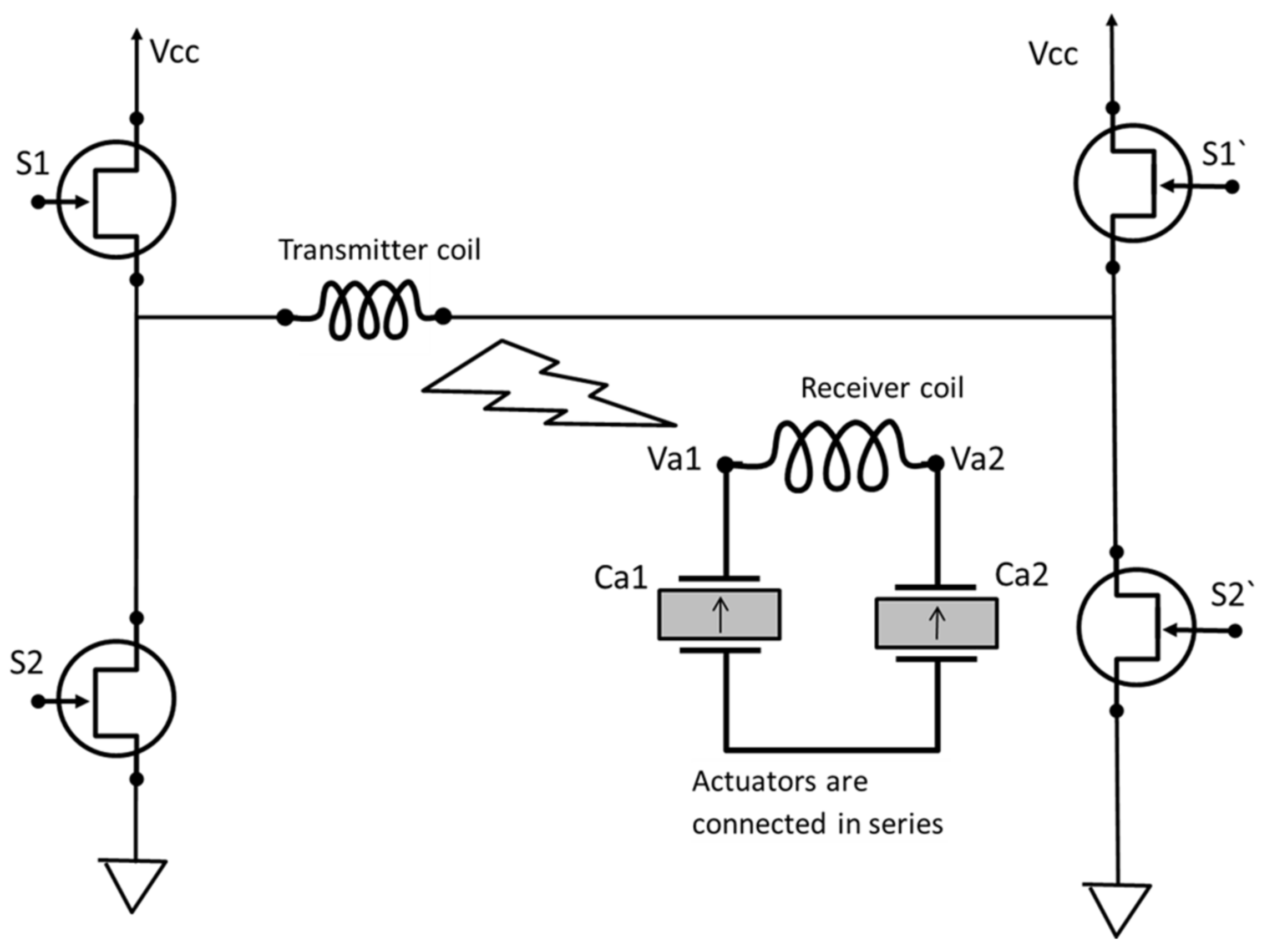
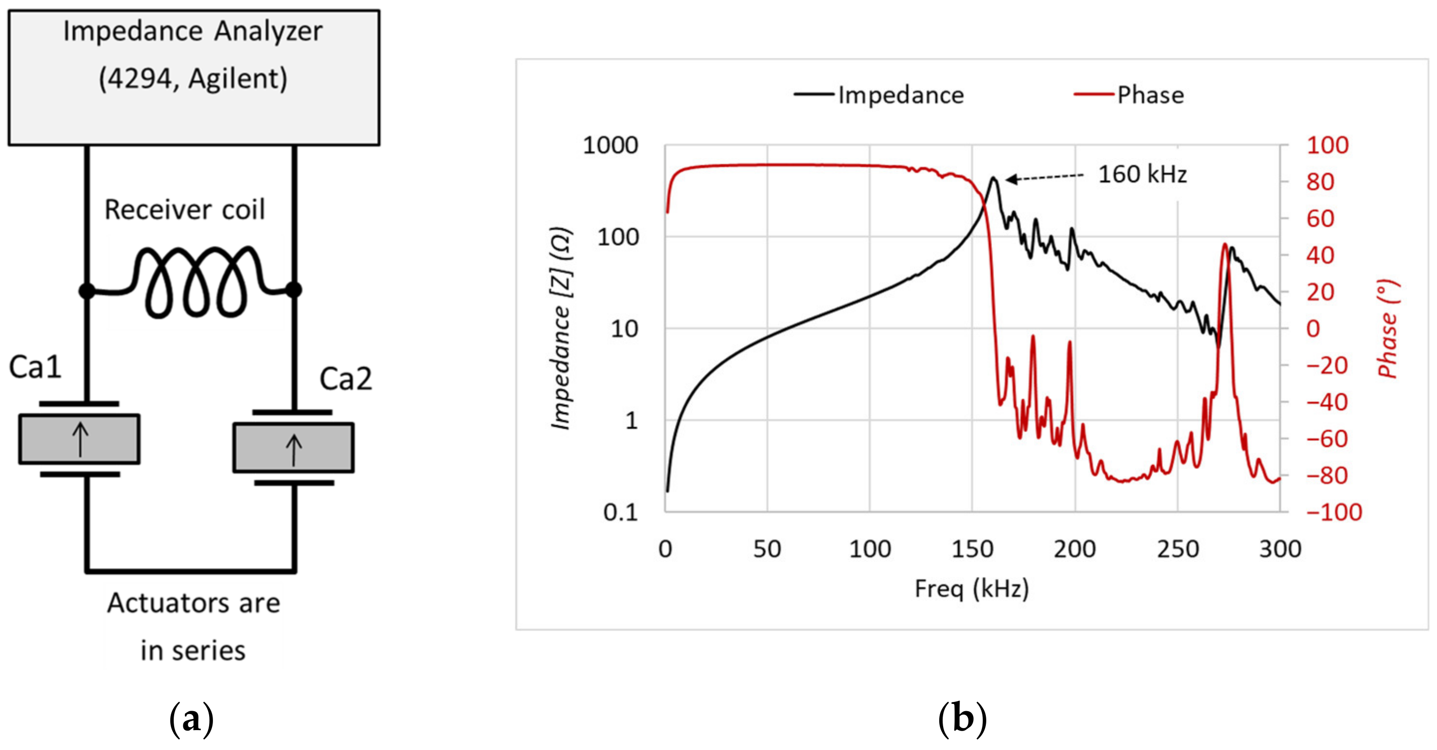
At the receiver side, the receiver coil is in parallel to the piezoelectric multilayer actuators, which are connected in series. When this LC network was connected to an impedance analyzer (4294, Agilent, Santa Clara, CA, USA) as seen in Figure 8a, the magnitude of the impedance and phase spectra were measured. Since the inductance (L) of the receiver coil is 24 µH, and equivalent capacitance C for the serially connected multilayer actuators is 40 nF, then the natural resonance frequency for the LC network can be found as 162.4 kHz. This frequency value is quite close to the experimentally obtained value that is 160 kHz (Figure 8b).
The LC configuration of the receiving coil (L) and the equivalent capacitance (C) of the piezoelectric multilayer actuators in the stator act as a filter. The voltage waveform accumulated on the piezoelectric actuators are modified sawtooth waveforms. Without a physical connection between the driving electronics and the motor, these signals allow the motor to run. Note that connection of the receiver coil and the multilayer actuators in series can cause one actuator to expand and the other to shrink.
Wireless driving was demonstrated on a positioning stage, in which a two-phase piezoelectric inertia-type motor was embedded. Figure 9 shows the details of the wireless drive electronics, the transmitter, and the receiver coils with the positioning stage. PWM signals for the booster and for the two half bridges, as well as the timing signals for the positioning stage, were generated by programing a microcontroller development kit (CY8CKIT-059 PSoC 5LP, Infineon Technologies AG, Neubiberg, Germany). The generated PWM signals with their timing sequences were applied to a Booster and two half bridge switching elements. The same switching Gallium Nitride high electron mobility transistors (GaN HEMT, EVAL-HB-Parallel GaN, Infineon Technologies AG, Neubiberg, Germany) are used in the booster and the two half bridges for their high frequency operation capability with small switching losses. While the booster converts DC 24 V to 40 V, the PWM coded sawtooth driving signals cause the two half bridges to operate like one full bridge, as seen the schematic in Figure 7. After the magnitudes of the PWM signals were amplified from 5 V to 40 V by the full bridge configuration of the GaN transistors, the PWM signals at 1 MHz were directly applied to the transmitter coil (24 µH, Vishay IWTX4646DCEB240JF1). An identical coil, placed 0.7 cm apart from the transmitter coil, was used as the receiver coil.
The receiver coil, which makes an LC network with the serially connected capacitances of the multilayer actuators, picked the PWM signals at 1 MHz. The response of the LC network during slip time was the same as in the wired driving condition, except equivalent resistance is due to the losses of the receiver coil’s inductance L (24 µH) and serially connected capacitance of the multilayer actuators C (40 nF). As can be seen in Figure 10, the damping factor and thus the equivalent resistance compared to wired driving are smaller. Sinusoidal ringing due to step and natural responses is not damped out instantly, but the effect is visible through each period. However, slow charging and discharging by the PWM signals are visible as in the case of the wired drive.

4. Wireless Burst Waveform Drive and Step Movement Measurements

When driving a piezoelectric motor wirelessly, the positioning ability of the piezoelectric stages should be evaluated. A nanopositioning stage equipped with a piezoelectric inertia-type motor can easily make very small steps. If step movements are not small enough, the actuators in a stage can be operated with DC voltage to obtain nanometer resolutions. When driving an inertia-type motor wirelessly, obtaining smaller steps would be limited by the number of driving pulses transmitted to the receiver coil. Precision of a stage would be limited by the smallest number of driving pulses that can make a slider move. In our case even a single driving pulse can make the slider move.
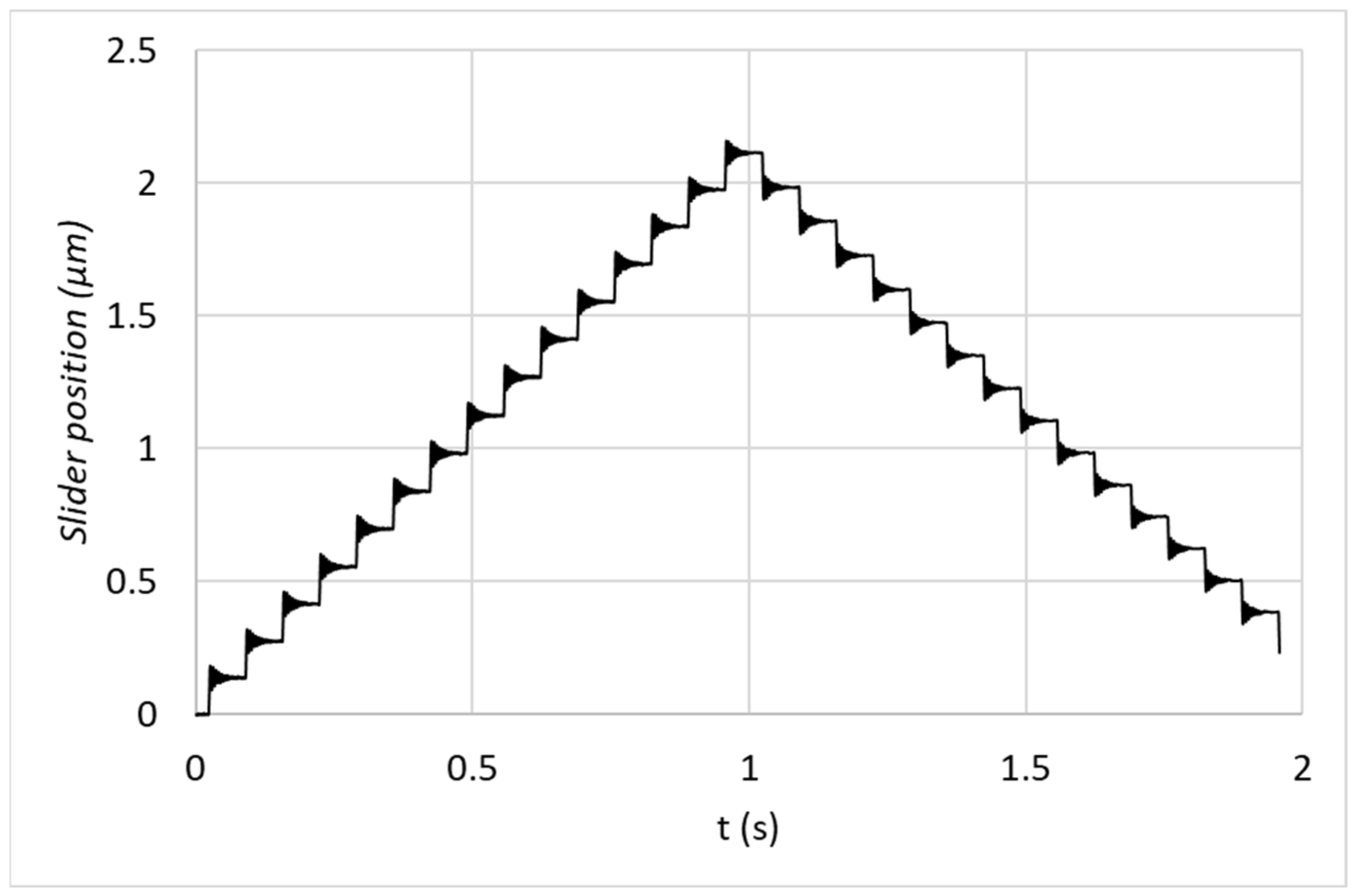
To examine the positioning ability of the piezoelectric inertia-type motor, wireless drive electronics send single steps to the receiving coil 15 times in one direction and 15 times to make the stage to come to its original position. The slider position was captured by an encoder-type position sensor integrated into the positioning stage. Even if our aim is to energize position sensor electronics wirelessly, the position sensor signals were transferred to a control electronics by the existing cables on the stage. As can be seen in Figure 11, even a single driving pulse (or signal) can generate a movement. Figure 11 demonstrates that open loop step movements as small as 140 nanometers in one direction and 125 nanometers in the opposite direction can be obtained. These values can vary with the position of the transmitter and receiver coils as coupling can change with the position of the coils. During those measurements, the distance between the receiver and the transmitter was fixed at 0.7 cm. The step size can be optimized with the magnitudes of the driving signals, the carrier frequency (in our case, frequency of the PWM signals), and motor operating frequency (30 kHz).
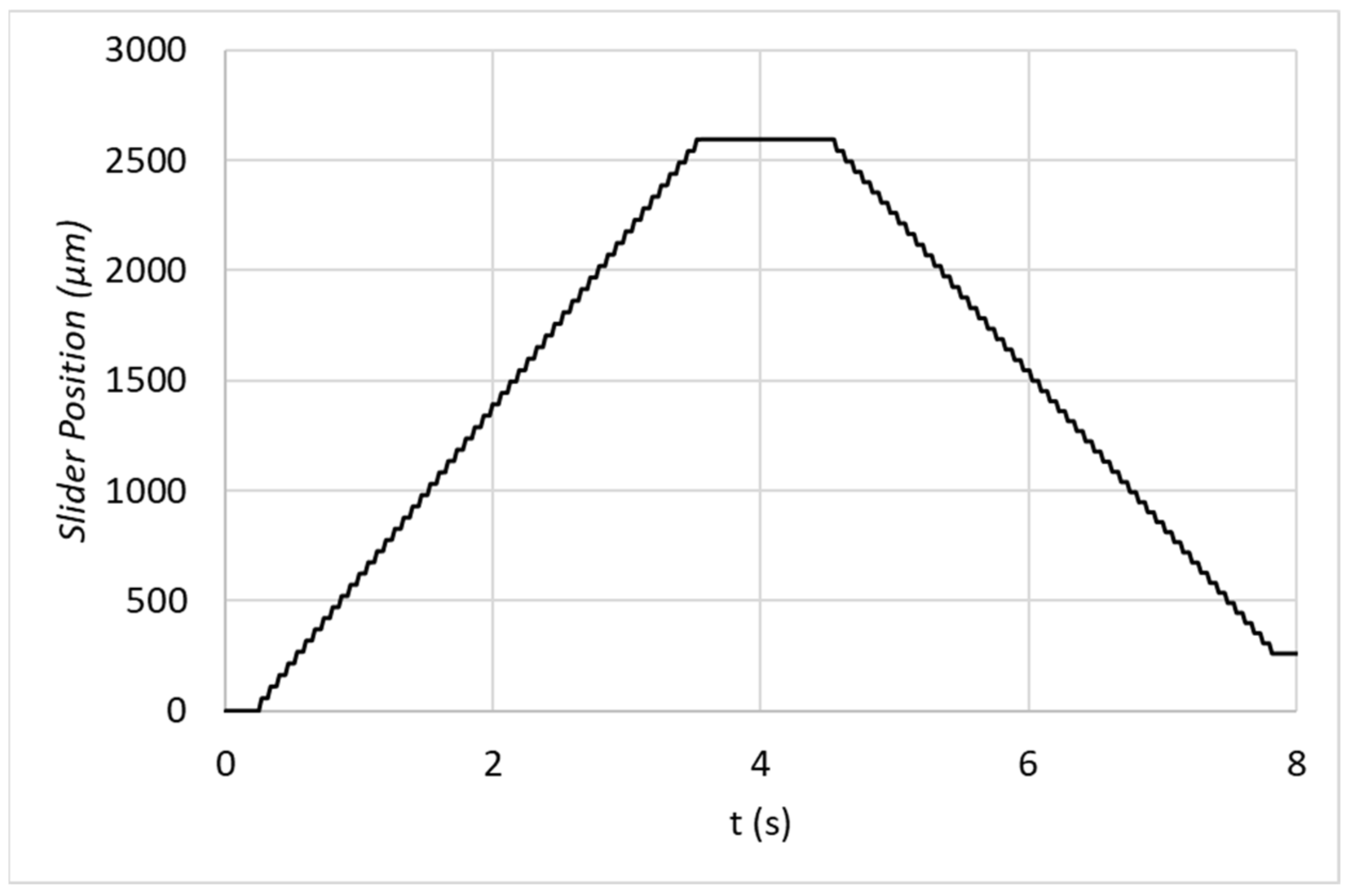
In the following measurements, the driving number of pulses for each step movement sent to the receiver coil was increased to 100 and applied 50 times to move the slider in one direction and 50 times to move it in the opposite directions. 100 driving pulses made the slider move about 52 µm, which made the movement per pulse to be about 0.52 µm in one direction and 0.47 µm in return direction. As shown in Figure 12, when multiple driving pulses are sent, mean step size per pulse increased significantly. However, consistency of direction-dependent step size difference is visible. The direction dependency can be related to mechanics of the motor or tolerance of the multilayer actuators. Detailed analysis for finding the reason is left for future work.
The single step duration, which is only 33 µs, is not long enough for the slider to follow the friction coupler because it is heavier and thus has longer response time compared to the friction coupler. As a result, the step size in response to a single step is smaller than the movement per pulse for multiple pulse driving.

5. Conclusions

A wireless driving method for piezoelectric inertia-drive-type motors is introduced (to the best of our knowledge) for the first time. In other words, we propose a wireless method of energy transfer from electrical into mechanical form. The proposed method can lead to the realization of cableless nanopositioning stages.
In an inertia-type motor, the stick phase, which corresponds to slow charging or discharging of the multilayer actuators, is realized by changing the duty ratio of PWM signals at very high frequency. The slip phase, on the other hand, occurs with either a natural response or step response of an RLC network. In the RLC network, L is the inductor used in front of the multilayer actuators, C is the capacitance of the multilayer actuators, and R is the equivalent resistance of the inductor and the capacitance losses of the multilayer actuators.
Class-D amplifier topology, realized with GaN transistors, offers quite an elegant solution for driving piezoelectric inertia motors wirelessly. Usage of GaN transistors with their fast switching and low switching losses can increase the bandwidth of a typical class-D amplifier to more than 500 kHz. The proposed driving method can also be used for wired drive of piezoelectric inertia-type motors. Since power dissipation from the drive electronics takes place only during operation of a positioning stage, a drive electronics can operate at a high efficiency.

6. Patents

A German patent is granted and there are some further applications.

Author Contributions

Conceptualization, B.K.; methodology, B.K.; software, S.K. and A.H.; validation, B.K., S.K. and A.H.; investigation, B.K.; writing—original draft preparation, B.K., S.K. and A.H.; writing—review and editing, B.K.; visualization, B.K.; supervision, B.K.; project administration, B.K. All authors have read and agreed to the published version of the manuscript.

Funding

This research received no external funding.

Data Availability Statement

Not applicable.

Conflicts of Interest

The authors declare no conflict of interest.

References

  1. Uchino, K. Piezoelectric Actuators and Ultrasonic Motors; Springer: New York, NY, USA, 1996; ISBN 0-7923-9811-4. [Google Scholar]
  2. Uchino, K. Piezoelectric ultrasonic motors: Overview. Smart Mater. Struct. 1998, 7, 273–285. [Google Scholar] [CrossRef]
  3. Hunstig, M. Piezoelectric Inertia Motors—A Critical Review of History, Concepts, Design, Applications, and Perspectives. Actuators 2017, 6, 7. [Google Scholar] [CrossRef] [Green Version]
  4. Zhao, C.S. Ultrasonic Motors Technologies and Applications; Springer: Berlin/Heidelberg, Germany, 2011; ISBN 978-3-642-15305-1. [Google Scholar]
  5. Spanner, K.; Koc, B. Piezoelectric Motors, an Overview. Actuators 2016, 5, 6. [Google Scholar] [CrossRef]
  6. Higuchi, T.; Watanabe, M. Apparatus for Effecting Fine Movement by Impact Force Produced by Piezoelectric or Electrostrictive Element. U.S. Patent 4 894 579, 16 January 1990. [Google Scholar]
  7. Pohl, D.W. Dynamic piezoelectric translation devices. Rev. Sci. Instrum. 1987, 58, 54–57. [Google Scholar] [CrossRef]
  8. Suzuki, M.; Hosaka, H.; Morita, T. Resonant Type Smooth Impact Drive Mechanism Actuator with Two Langevin Transducers. Adv. Robot. 2012, 26, 277–290. [Google Scholar] [CrossRef]
  9. Hunstig, M.; Hemsel, T.; Sextro, W. Stick-Slip and Slip-Slip Operation of Piezoelectric Inertia Drives. Part I: Ideal Excitation. Sens. Actuators A Phys. 2013, 200, 90–100. [Google Scholar] [CrossRef]
  10. Cheng, G.; Hu, Y.; Wen, J.; Zeng, P.; Xing, C. Piezoelectric inertial rotary actuators based on asymmetrically clamping structures. Sens. Actuators A Phys. 2015, 223, 125–133. [Google Scholar] [CrossRef]
  11. Page, D.F.; Hindson, W.D.; Chudobiak, W.J. On solid-state Class-D systems. Proc. IEEE 1965, 53, 423–424. [Google Scholar] [CrossRef]
  12. Leach, W.M., Jr. Introduction to Electroacoustics and Audio Amplifier Design, 2nd ed.; Kendal/Hunt Publishing Company: Dubuque, IA, USA, 1999; ISBN 9781465215703. [Google Scholar]
  13. Nabae, A.; Takahashi, I.; Akagi, H. A new neutral-point-clamped PWM inverter. IEEE Trans. Ind. Applicat. 1981, 17, 518–523. [Google Scholar] [CrossRef]
  14. Janocha, H.; Stiebel, C. New approach to a switching amplifier for piezoelectric actuators. In Proceedings of the 6th International Conference on New Actuators, Bremen, Germany, 17–19 June 1998; pp. 189–192. [Google Scholar]
  15. Koc, B.; Kist, S.; Hamada, A. Efficient Driving Method for Piezoelectric Inertia Motors. In Proceedings of the ACTUATOR 2022, International Conference and Exhibition on New Actuator Systems and Applications, Mannheim, Germany, 29–30 June 2022; pp. 1–4. [Google Scholar]
  16. Ahire, D.B.; Gond, V.J. Wireless power transfer system for biomedical application: A review. In Proceedings of the International Conference on Trends in Electronics and Informatics (ICEI 2017), Tirunelveli, India, 11–12 May 2017; pp. 135–140. [Google Scholar]
  17. Qiao, X.; Niu, S.; Lin, J.; Chen, M.; Wu, Y. A Novel Magnetically Coupled Resonant Wireless Power Transfer Technique Used in Rotary Ultrasonic Machining Process. In Proceedings of the 2021 IEEE Wireless Power Transfer Conference (WPTC), San Diego, CA, USA, 1–4 June 2021; pp. 1–4. [Google Scholar] [CrossRef]
  18. Kindl, V.; Kavalir, T.; Sika, J.; Hnatik, J.; Krizek, M.; Frivaldsky, M. Wireless Power Transmission System for Powering Rotating Parts of Automatic Machineries. Energies 2022, 15, 6856. [Google Scholar] [CrossRef]
  19. Koc, B.; Delibas, B. Design of a 2-phase Piezoelectric Inertia Drive Type Motor. In Proceedings of the ACTUATOR 2022, International Conference and Exhibition on New Actuator Systems and Applications, Mannheim, Germany, 29–30 June 2022. [Google Scholar]
  20. Koc, B.; Delibas, B. Impact Force Analysis in Inertia-Type Piezoelectric Motors. Actuators 2023, 12, 52. [Google Scholar] [CrossRef]
  21. Imura, T. Wireless Power Transfer; Springer: Singapore, 2020; pp. 1–5. ISBN 978-981-15-4580-1. [Google Scholar]
  22. Prodic, A.; Maksimovic, D.; Erickson, R.W. Design and implementation of a digital PWM controller for a high-frequency switching DC-DC power converter. In Proceedings of the IECON’01. 27th Annual Conference of the IEEE Industrial Electronics Society (Cat. No.37243), Denver, CO, USA, 29 November–2 December 2001; Volume 2, pp. 893–898. [Google Scholar] [CrossRef]
Figure 1. (a) Stator of the two-phase piezoelectric inertia-drive-type motor. (b) Synchronous deformations of the multilayer actuators in their thickness directions are transferred into a rotary movement of the friction coupler.
Actuators 12 00136 g001
Figure 2. Idealized mirrored and truncated sawtooth signal waveforms to drive the two-phase inertia-type motor (T is the period). When the multilayer actuators are exposed to these waveforms, as one actuator expands, the other shrinks synchronously.
Actuators 12 00136 g002
Figure 3. The complementary PWM signals applied to S1 and S2 allow the capacitance of the actuator 1 to charge by gradually increasing the ON time of S1 and OFF time of S2. Similarly, the same complementary PWM signals applied to S2′ and S1′ allow the capacitance of the actuator 2 to discharge by gradually increasing the ON time of S2′ and OFF time of S1′.
Actuators 12 00136 g003
Figure 4. (a) Voltage and current waveforms during fast charging and slow discharging of the piezoelectric multilayer actuator. (b) Voltage and current waveform during fast discharging and slow charging of the piezoelectric multilayer actuator.
Actuators 12 00136 g004
Figure 5. Fast discharging of the multilayer actuator is according to natural response of an RLC network.
Actuators 12 00136 g005
Figure 6. One period (33 µs) of the complementary PWM signals. Frequency of the PWM is 1 MHz. Magnitudes of both PWM signals are changing from 0 to 5 V.
Actuators 12 00136 g006
Figure 7. Schematic of the wireless piezoelectric inertia-type motor driving using class-D amplifier topology. The two multilayer actuators in the stator of the motor are connected in series with the receiver coil.
Actuators 12 00136 g007
Figure 8. (a) Connection of the receiver side to the impedance analyzer. (b) Impedance magnitude and phase spectra of the receiver coil connected in parallel to serially connected piezoelectric multilayer actuators.
Actuators 12 00136 g008
Figure 9. First step to a cableless positioning stage. Prototype wireless driving electronics of a two-phase piezoelectric inertia-type motor. 1—microcontroller, 2—Booster to convert DC 24 V to 40 V, 3—GaN-Tr Half bridge, 4—GaN-Tr Half bridge, 5—Transmitter coil, 6—Receiver Coil, 7—Positioning stage.
Actuators 12 00136 g009
Figure 10. (a) The complementary modified sawtooth waveforms at the connection points of the receiver coil and the multilayer actuators. Period of the motor operating frequency is 33 µs (30 kHz). (a) at point Va1, (b) at point Va2 (see Figure 7).
Actuators 12 00136 g010
Figure 11. Slider position when single driving pulses are sent to the receiver coil to generate step movement 15 times and the following single steps again 15 times to make the slider return to its original position. Each single step can generate a mean step movement of about 140 nm in one direction and 125 nm in the reverse direction.
Actuators 12 00136 g011
Figure 12. Slider position when 100 driving pulses are sent to the receiver coil for 50 times in one direction and again 50 times in the reverse direction. A direction-dependent step size difference is visible in this measurement also.
Actuators 12 00136 g012
Disclaimer/Publisher’s Note: The statements, opinions and data contained in all publications are solely those of the individual author(s) and contributor(s) and not of MDPI and/or the editor(s). MDPI and/or the editor(s) disclaim responsibility for any injury to people or property resulting from any ideas, methods, instructions or products referred to in the content.

