1. Introduction
Autonomous driving technology is changing many aspects of our daily lives. Robot taxis, shuttles, and delivery vehicles [
1,
2] with autonomous driving technology are nearing commercialization and are being applied to various industries and service fields such as logistics, heavy equipment, and medical care [
3,
4,
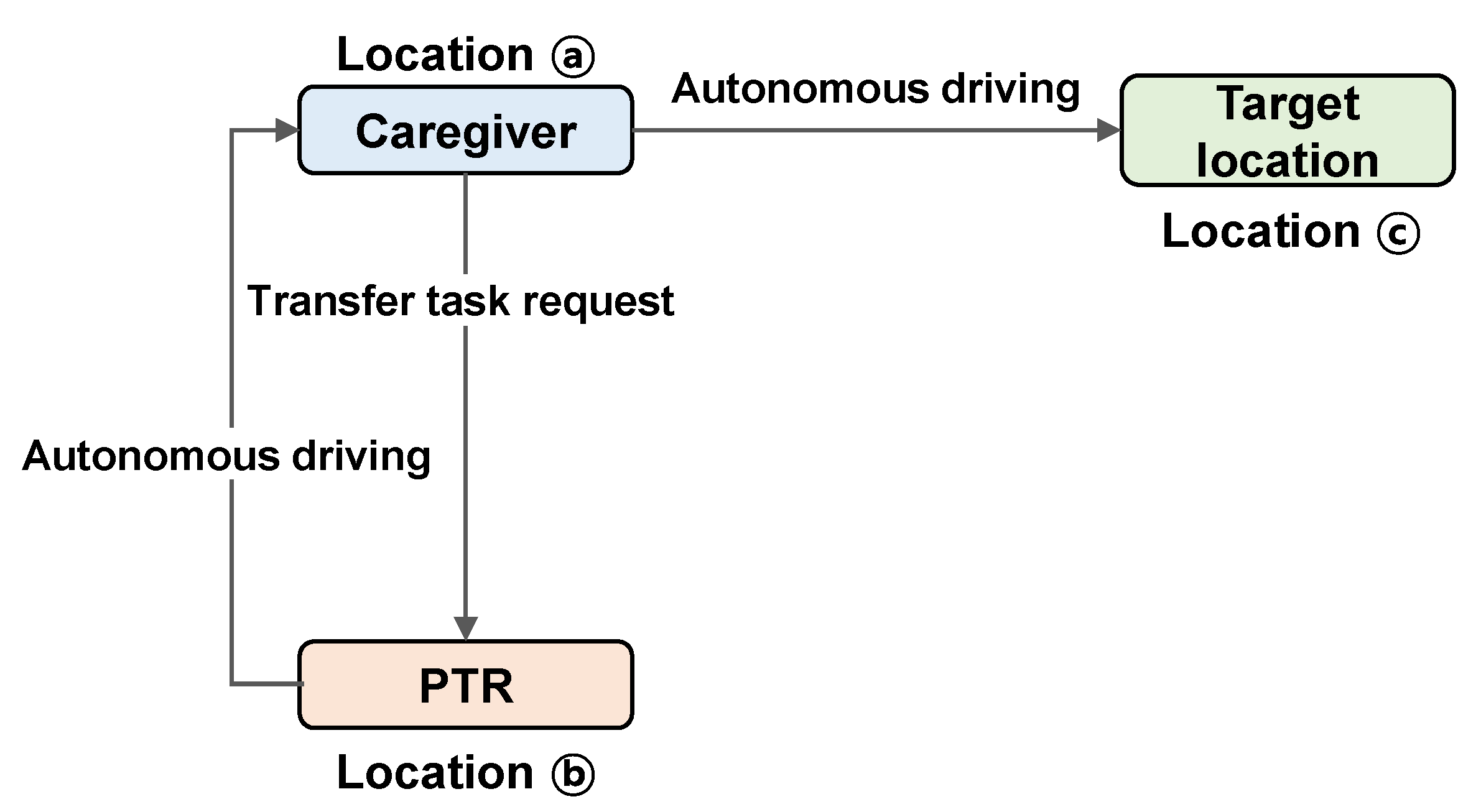
5]. In this study, we focused on the autonomous driving technology of a patient-transfer robot (PTR) applied to medical facilities, one of the various application fields of autonomous driving technology. For the implementation of autonomous driving technology, it is necessary to have elements of environment recognition through sensor information, workspace mapping, localization, path planning, and motion control [
6]. Among these, this study deals with the path planning of the robot to move from the current position to the goal and the control of the robot to travel the planned path under the assumption that the building of the work environment (also called the map) and localization have been completed by SLAM technology.
The first issue, path planning, consists of global path planning and local path planning. Global path planning is an offline route-planning method that creates a path based on a global map of the workspace [
7,
8]. Recently, geofencing methods that generate paths and avoid obstacles via a virtual fence of the obstacles were used in [
9,
10,
11]. On the other hand, local path planning is an online planning method, and based on limited information obtained from robot sensors, it interacts with the surrounding environment and plans a moving path [
6,
12]. In a static workspace where the workspace does not change, it is possible to work with only global path planning. However, the general work environment has a very dynamic nature. Therefore, local path planning is essential due to changes in the spatial arrangement or dynamic obstacles such as other robots or workers (people). After all, securing navigation ability in a dynamic environment of a mobile robot is one of the most important methods in mobile robot navigation, therefore several studies have been conducted in this area [
13,
14,
15,
16,
17].
There have been many studies to resolve the issue. The artificial potential field (APF) [
18] is a way to reach a destination through the sum of all vectors in which an attraction vector is generated in the destination direction and a repulsive force vector is generated in the direction of the destination. In the case of APF, the calculation load is small, and the implementation is easy. On the other hand, there are disadvantages in that it is difficult to avoid the local minima and difficult to tune the parameters of the algorithm. Navigation based on the Genetic Algorithm [
19] mimics the process of evolution occurring in living organisms, and it is possible to derive a solution with a high level of accuracy, but it is not suitable for application in a dynamic environment. Particle swarm optimization (PSO) [
20] is a navigation method that mimics the behavior observed in the migration of migratory birds or schools of fish. PSO can implement algorithms at high speed but can be exposed to local minima in complex environments. Ant colony optimization [
21] is an algorithm that simulates the phenomenon in which ants create an optimal path through pheromones. It has the advantage of having a small number of parameters to be tuned to implement the algorithm but has the weakness of long calculation time.
The global path-planning method, which plans the path of the robot assuming a static working environment, has the advantage of being able to easily generate the optimal path to the destination. However, in a real navigation environment, a reactive manner is essential because it must move while responding to dynamically changing environments. Due to the nature of the local path generation method, which generates a path with only limited information, it is excellent for immediate obstacle avoidance but is not suitable for creating an optimal path from a long-term perspective. Therefore, in this study, we propose an optimal path-generation method in a dynamic environment via the convergence of the existing global path-generation method, which is difficult to use in a dynamic environment, and the existing local path-generation method, which has limitations in optimal path generation.
In this study, a hybrid path-planning algorithm is proposed to compensate for the weaknesses of the existing path-planning methods introduced above, such as excessive computational load, lack of the ability to overcome local minima, and having multiple tuning parameters. In other words, we propose a new path-planning method that compensates for the weaknesses of current methods through the convergence of two different categories of path-planning methods. To this end, the A-STAR method is applied as a global path planning method, and the Analytic hierarchy process (AHP) [
22,
23] method is applied as a local path planning method. Through A-STAR, the optimality of the path and short path planning time performance is secured. In addition, AHP-based path planning, which has the characteristics of a multi-factor based decision-making method, enables a function to prevent collisions with obstacles in a real-time dynamic environment and path planning tailored to the navigation environment. In addition, since the mobile platform dealt with in this study is a patient-transfer robot used in medical facilities, an anti-sway control that minimizes the sway angle of the patient on board and a controller that enables stable movement of the PTR are designed. In summary, there are two main contributions of this paper. The first is proposing a new path-planning algorithm that compensates for the limitations of existing navigation algorithms. Through this, optimal path generation, avoidance of local minima, and short-time path generation were achieved. Secondly, we applied the proposed path-planning algorithm to a patient-transfer robot and designed a motion controller. The proposed controller tracks the reference path well and the patient’s sway is successfully reduced. Furthermore, unmodeled uncertainty and noise are handled via the Kalman filter. The simulation results support the contributions of this research.
The remainder of the paper is organized as follows:
Section 2 specifies the issues addressed in this study. The path-planning algorithm for autonomous driving is discussed in
Section 3, and the motion control of the PTR robot is addressed in
Section 4. In
Section 5, the performance of the proposed autonomous driving system is demonstrated through numerical simulations through a hospital environment map. In
Section 6 and
Section 7, discussions and conclusions about the research results are presented, respectively.
2. Problem Formulation
In this study, an autonomous driving method is developed in which a patient-transfer robot safely moves from one point to a designated point without collision with the external environment while transferring the patient. To this end, the generation of an appropriate movement path and motion control to move the robot along the corresponding path are essential [
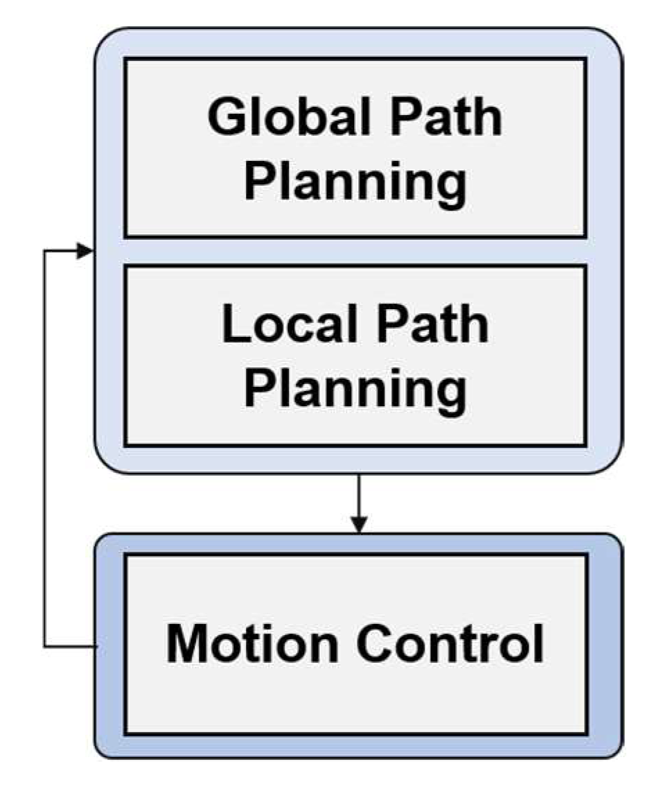
24]. For autonomous driving of a mobile robot platform, a path planning module that generates a path from the starting position to the goal position and a motion controller to move a mobile robot to a desired location are essential, as shown in
Figure 1.
The path planner is also called the higher-level controller while the motion controller is called the lower-level controller.
The path generation module includes global path planning and local path planning capabilities as shown in
Figure 1. Global path planning plans the robot’s travel path based on a given (or known) map. Therefore, through this step, the optimal path for the robot to move to the goal can be obtained on the given map.
Next, local path planning creates a path to the destination within a range that the robot can recognize. Even though the optimal path from the location of the robot to the destination is generated through global path planning, this is a path based on the initially given map, which is when the environmental changes are not applied. However, in reality, while the robot is moving toward its goal, environmental changes such as the appearance of previously non-existent static or dynamic obstacles in the workspace or changes in the workspace may occur.
Finally, the motion control level drives the robot to the goal position. Particularly, the focus of this study is to move the mecanum-wheel-based patient-transfer robot (PTR) to the desired position as well as to reduce the sway angle of the patient during the movement of the PTR.
3. A Hybrid Path Planning for Autonomous Driving
This section deals with the details of path planning for autonomous driving of PTR. In this study, a new path-planning method is proposed through the convergence of the two different path-planning methods, which consist of global path planning based on the given environment information and local path planning based on robot perception information. The two functions are not only essential elements for autonomous driving of mobile platforms but also enable complete autonomous driving through mutual complement.
3.1. A-STAR-Based Global Path Planning
In the navigation of a mobile robot, global path planning is required to plan a path from the robot’s current location to its destination. Global path planning is performed assuming a situation in which map information for the workspace of a mobile platform is given or a situation in which a workspace map is created through SLAM (Simultaneous Localization and Mapping). In this study, one of the most widely used global path-generation methods, the A-STAR algorithm, is applied [
7].
The A-STAR algorithm is one of the graph search algorithms that finds the shortest path from a given starting point to a goal point. This algorithm is similar to Dijkstra’s algorithm [
8], but the difference is that it uses a “heuristic estimation value”, which is a ranking value that estimates the best path through the vertex for each vertex, as shown in Equation (1).
where
represents the node in which the robot is located,
is the cost from the starting node to the current node
, and
is a heuristic function for predicting the minimum cost from
to the goal. In Algorithm 1, the detailed planning procedure of A-STAR is explained.
| Algorithm 1 Pseudo code of the A-STAR algorithm |
| | Input: Map |
| | nodes, n.f =, n.g =, |
| | list = empty, (create an empty list) |
| | liststart.g = 0, start.f = h (start) |
| | while (list ) |
| | | current = min (n.f), and remove current from list |
| | | if current = goal node then |
| | | Success; |
| | | end |
| | nodes N, (adjacent to current) |
| | | if (N.g > (current.g + cost of from N to current)) |
| | | N.g = current.g + cost of from N to current |
| | | N.f = N.g + H(N) |
| | | N.parent = current |
| | | add N to list if isn’t there already |
| | | end |
| | end |
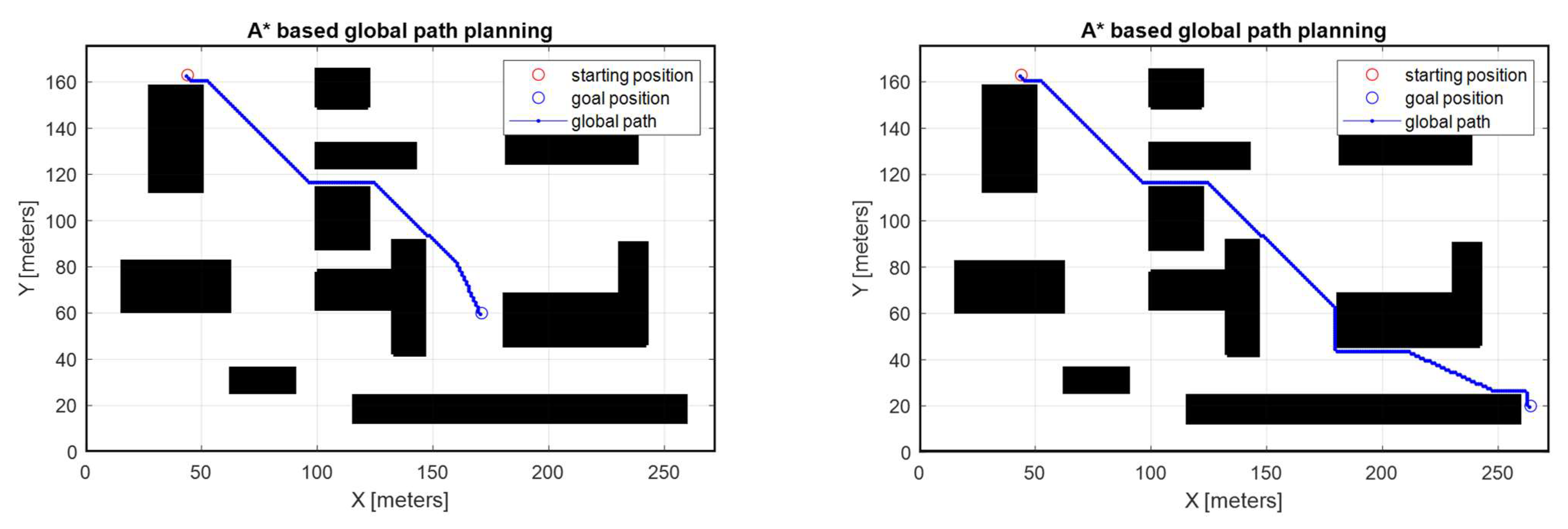
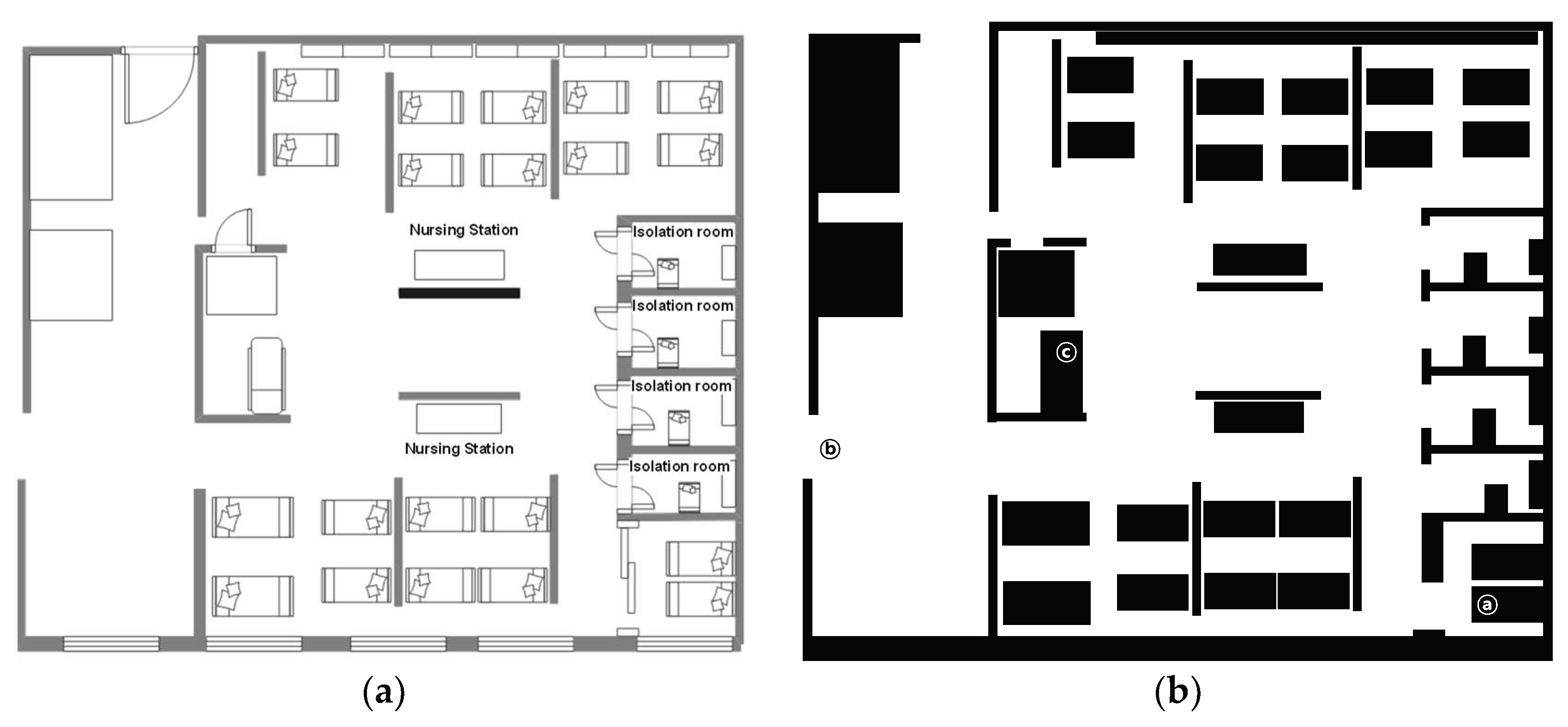
Figure 2 shows the result of global path planning based on A-STAR. The blue line represents the movement path of the mobile robot and the black polygons are obstacles that the robot cannot move, and it is assumed that the robot travels from the initial position represented by the red circle to the target point represented by the blue circle. A-STAR has been shown to generate the optimal path under given complex environments where the total distances of travel are 176.69 m and 292.71 m. Map information about the mobile platform’s workspace must be given for global path planning. In other words, it is necessary to assume that the workspace is static without any change at the moment of establishing the global path. However, in the field where the actual mobile platform is operated, unlike the initially given spatial information, new obstacles or facilities may be placed at random places, or moving obstacles such as other workers or mobile platforms may exist. The former case is called a static environment. However, the actual working environment is a dynamic environment. Therefore, the path must continuously regenerate as the environment changes. For this, local path planning is essential. Local path planning has a function of immediately generating a robot’s path in response to changes in the environment. The robustness in the presence of these environmental changes consequently improves the performance of the whole path planning.
3.2. AHP-Based Local Path Planning
This section discusses local path planning strategy. In order for a robot to safely move to its destination without colliding with other objects in a continuously changing workspace, it is essential to generate a path considering the changing environment. In order to tackle this requirement, the Analytic Hierarchy Process (AHP)-based [
25] path-planning algorithm is considered a local path-planning method. The AHP-based path-planning method is an application of the AHP technique to the path-planning problem of a mobile robot and has the following advantages of AHP decision making. First, decisions can be made simultaneously by considering multiple criteria. Second, the user’s preference for the importance of elements (elements considered important in mobile robots) can be reflected in decision-making. Because of these advantages, AHP was used in mobile robot path planning [
22,
23].
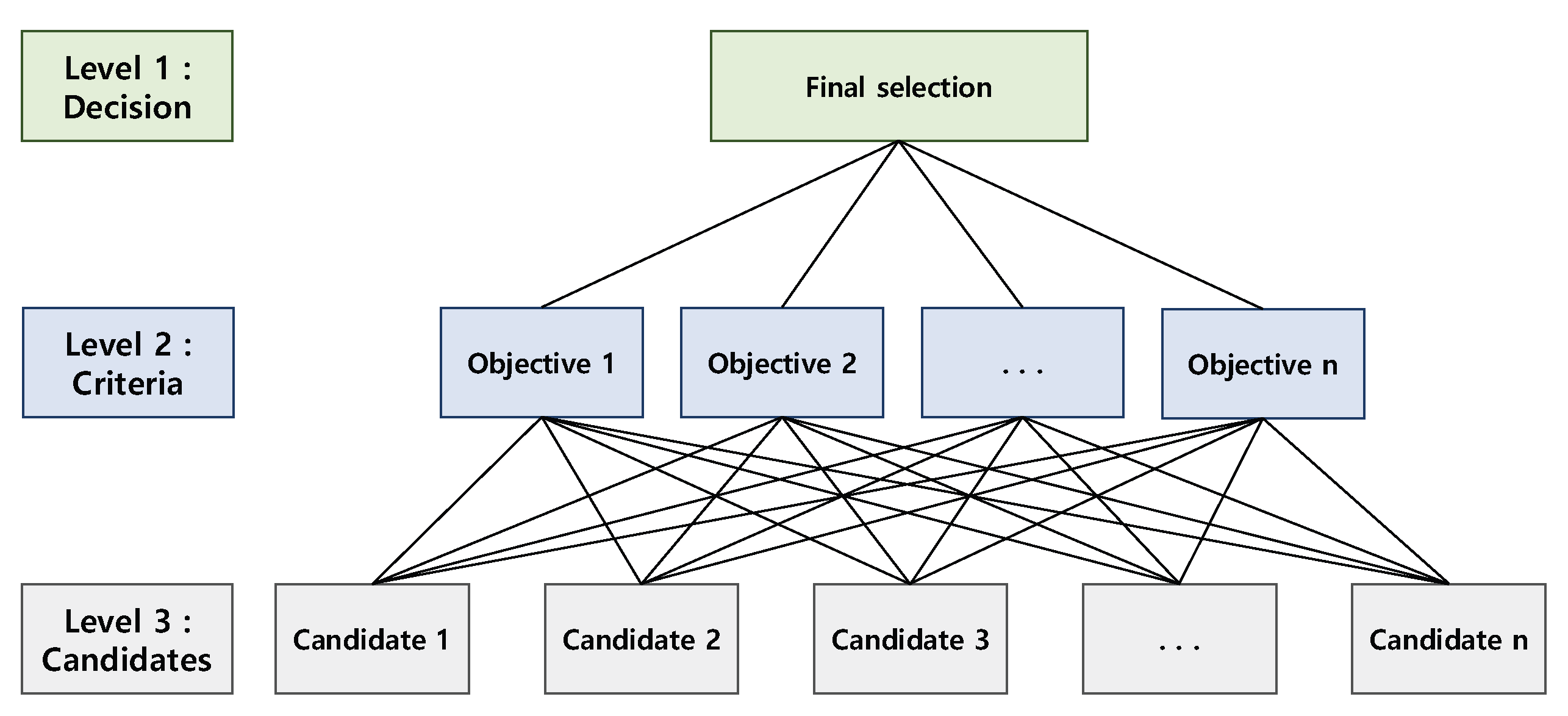
Figure 3 shows the general decision-making structure of the AHP. As shown in
Figure 3, the AHP-based decision-making structure consists of three layers: Final selection (decision), consideration items (criteria), and candidates. That is, it is a decision-making process that simultaneously considers multiple criteria in order to make a final selection (optimal solution) among multiple candidates. In addition, since the relative preference of the user (decision maker) for each criterion can be applied, it helps to decide what is suitable for the conditions and environment of decision-making.
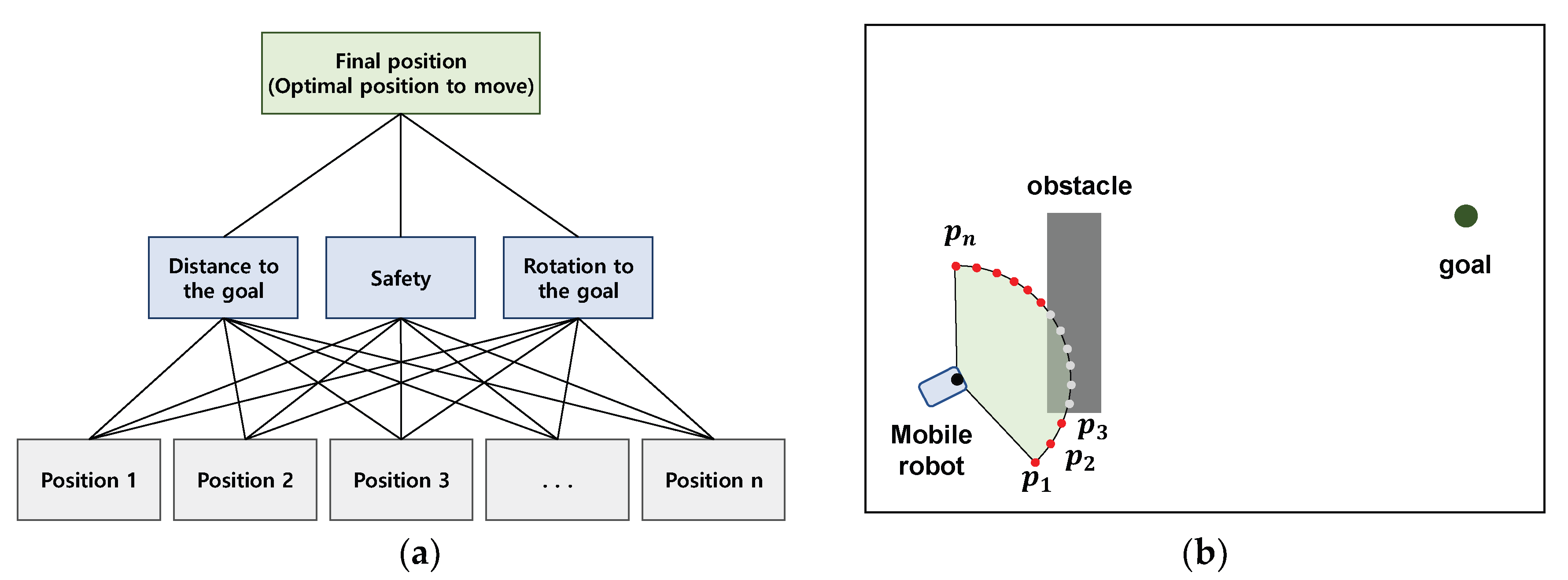
Figure 4a shows the AHP-based mobile robot path planning. The final selection, which is the first layer in the basic structure of AHP, represents the optimal position for the mobile robot to move. As the second layer, the distance to the goal
for each position that the robot can move, the degree of collision safety
, and the amount of rotation to orient to the destination
were used as criteria to be considered for decision-making. As the last layer, the positions
where the robot can move on the boundary of the region that can be sensed through the robot’s sensor are defined as the target group for decision-making. In addition, the relative importance of each criterion to be considered must be determined in order to make decisions suitable for the purpose of navigation. For example, in the case of navigation where the shortest-distance movement is important, the highest priority is given to
; in the case of navigation where collision safety is the top priority, the highest weight is given to
; and in situations where vibration or rapid movement of the transported object must be avoided, the maximum weight is given to
. For a more detailed description of AHP’s mobile robot path planning, it is recommended to refer to the following references [
22,
23,
26].
Figure 4b shows a situation to explain local path planning through AHP. In the figure, the red dots are points to which the robot can move, and they become a set of candidates. Assuming that the robot moves to each point, the final decision is made after calculating the distance from each point to the destination, the degree of safety, and the amount of rotation to aim for the destination, reflecting the relative importance of each criterion.
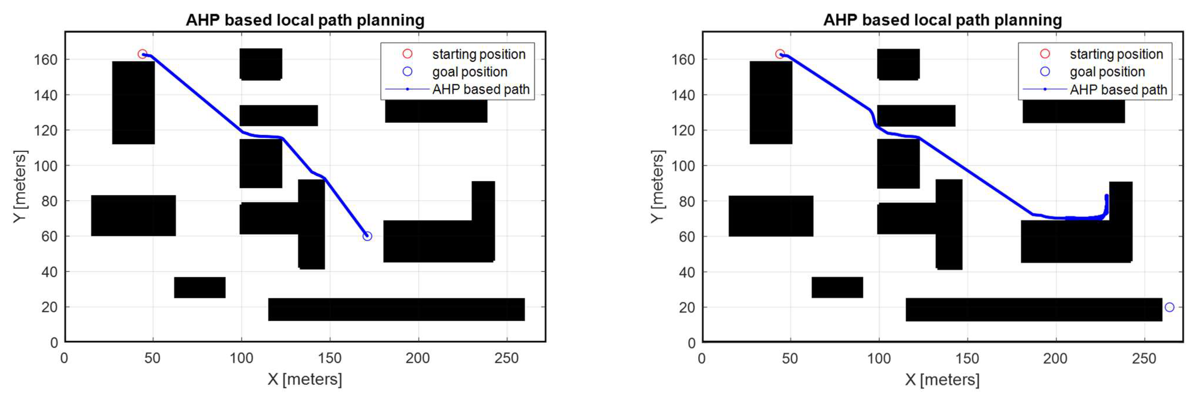
Figure 5 shows the results of AHP path planning under the same conditions as the A-STAR-based path planning. The importance of each criterion of AHP was defined as
0.70,
, and
, respectively. The total moving distances are 168.5 m and infinite, one is shorter than that of A-STAR. The first case is because A-STAR defines 8 cells surrounding each cell as the moving position, while AHP defines the points at the boundary of the robot sensor as the moving position. In other words, it can be said to be an improvement caused by a difference in resolution. The second is because of the local minima. Due to this, the robot cannot get out of the same area and eventually cannot reach the goal. This is a weak point of local path-planning methods such as AHP-based path planning. That is, this problem arises because AHP, which relies only on robot sensor information, cannot plan a path from a macroscopic point of view. To this end, we proposed a new path-planning algorithm that combines A-STAR and AHP. The strength of AHP is that it is a decision-making method that considers various factors simultaneously and that it can reflect the user’s preference for each factor to be considered. To show this, as shown in
Table 1, the AHP-based navigation performance with three different weights applied was compared. In the first row of
Table 1, the travel distance of scenario 2 is ‘
’; this means the robot cannot reach its goal due to the ‘local minima phenomenon’.
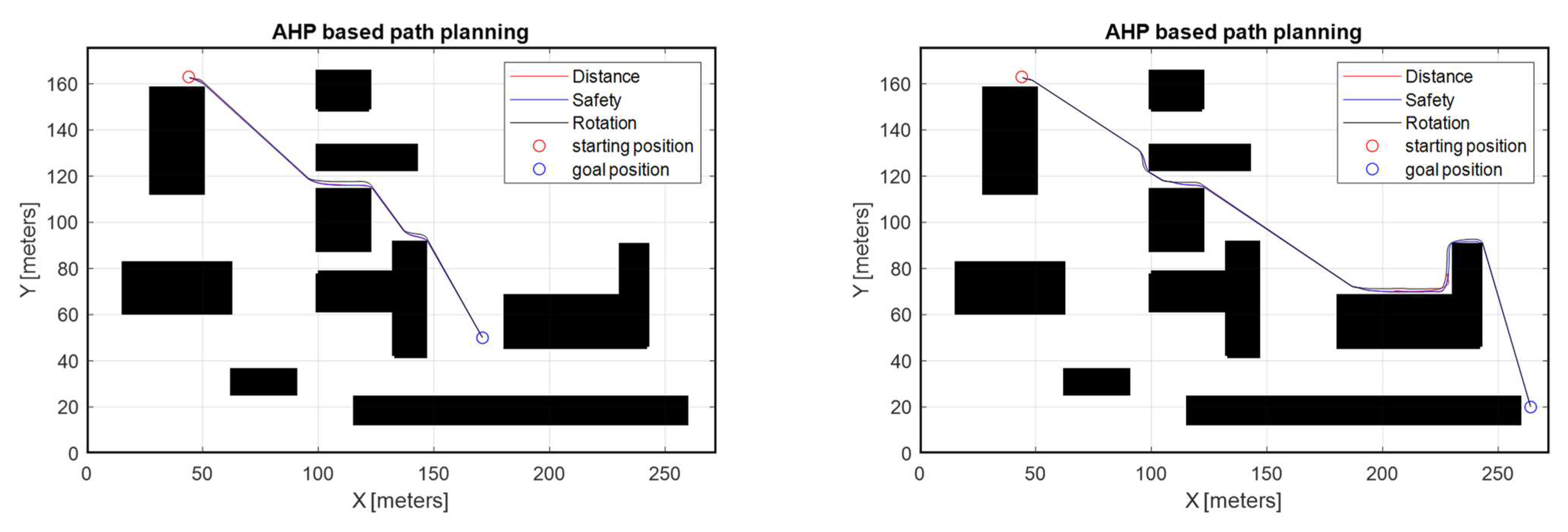
Figure 6 displays the different weighting-based path planning results. The simulation results show different paths that reflect weighting for AHP decision-making. However, in some cases, the local minima cannot be avoided, and this leads to an extreme increase in planning time. Moreover, when the results are compared with A-STAR-based path planning (
Figure 2), path optimality cannot be guaranteed. In
Figure 5 and
Figure 6, the advantages and disadvantages of the local path-planning (AHP) method are observed. The advantage of AHP-based path planning is that it is possible to generate a route based on the user’s preference, and the disadvantage is that there is a risk of falling into conditions such as local minima because it is impossible to generate an optimal path. Therefore, for effective path planning, a hybrid path-planning method combining the advantages of existing global route planning and local path-planning methods is required.
3.3. A Hybrid Path Planning Algorithm
Despite the various advantages of AHP, as confirmed in the previous subsection, AHP has limitations as a local path-planning method. Therefore, this leads to a limitation in that optimal path generation cannot be guaranteed because the path is planned based on limited (field of view of the robot’s sensor) information rather than the entire map’s information. To compensate for this, we proposed a novel path-planning algorithm that can actively respond to dynamic environments while guaranteeing the optimality of path planning by integrating the A-STAR-based global path-generation method and the AHP-based local path-generation method.
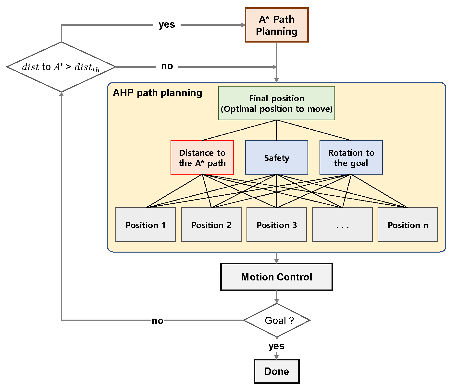
Figure 7 is a schematic diagram of the proposed hybrid path-planning algorithm. Firstly, a global path is generated by the A-STAR algorithm, and then a local path is created through AHP using the result. In the existing AHP, the distance from the robot’s movable position (decision candidates) to the goal was set as
, but in the proposed algorithm, the distance between the robot’s movable position and the closest A-STAR path is defined as
. That is, in generating the local path, the existing safety level and rotation of the robot to aim for the goal are considered, and at the same time, the path is generated by considering the distance from A-STAR, which is the optimal path. Later, after the robot moves along the path planned by the motion control module, the distance to the path A-STAR is measured, and if it is longer than the set distance, the process of regenerating the path through A-STAR is repeated.
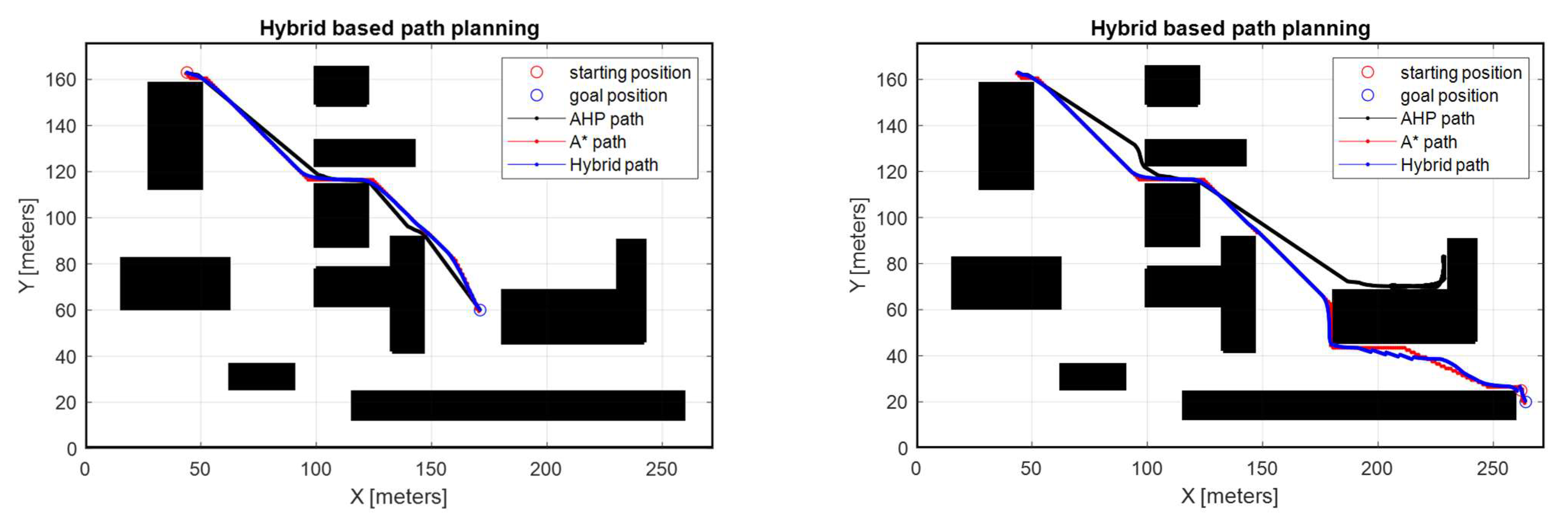
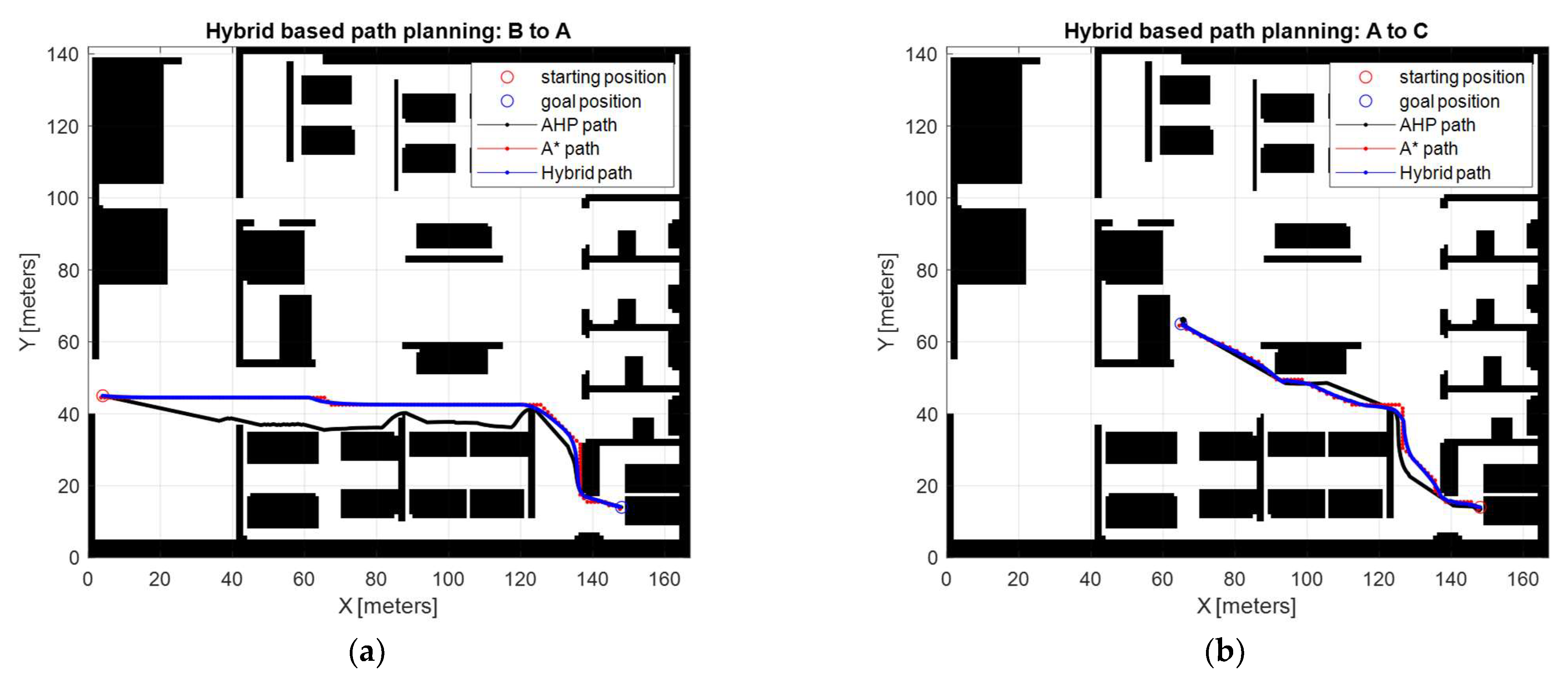
Figure 8 shows the navigation results through the proposed hybrid path-planning method. The simulation results are compared with A-STAR-based path planning and AHP-based path planning. As can be seen in the two scenarios in
Figure 8, it is confirmed that the hybrid path planning represented by the blue line maintains the trend of the optimal path (red line) of A-STAR and does not deviate from the characteristics of the AHP-based path planning (black line). In particular, even when the goal could not be reached based on AHP due to the occurrence of local minima, it also is confirmed that the proposed algorithm successfully created a path while maintaining the unique characteristics of A-STAR and AHP.
Table 2 shows the traveling distance based on each path-planning method, and it is shown that the proposed path-planning method shows the best performance in distance and rotation of the robot showing a non-abrupt change in orientation.
Table 3 and
Figure 9 demonstrate the results of the suggested path planning under different AHP preferences. In particular, the distance of each strategy is investigated, and the results depend on the preference of each objective and guarantee path optimality.
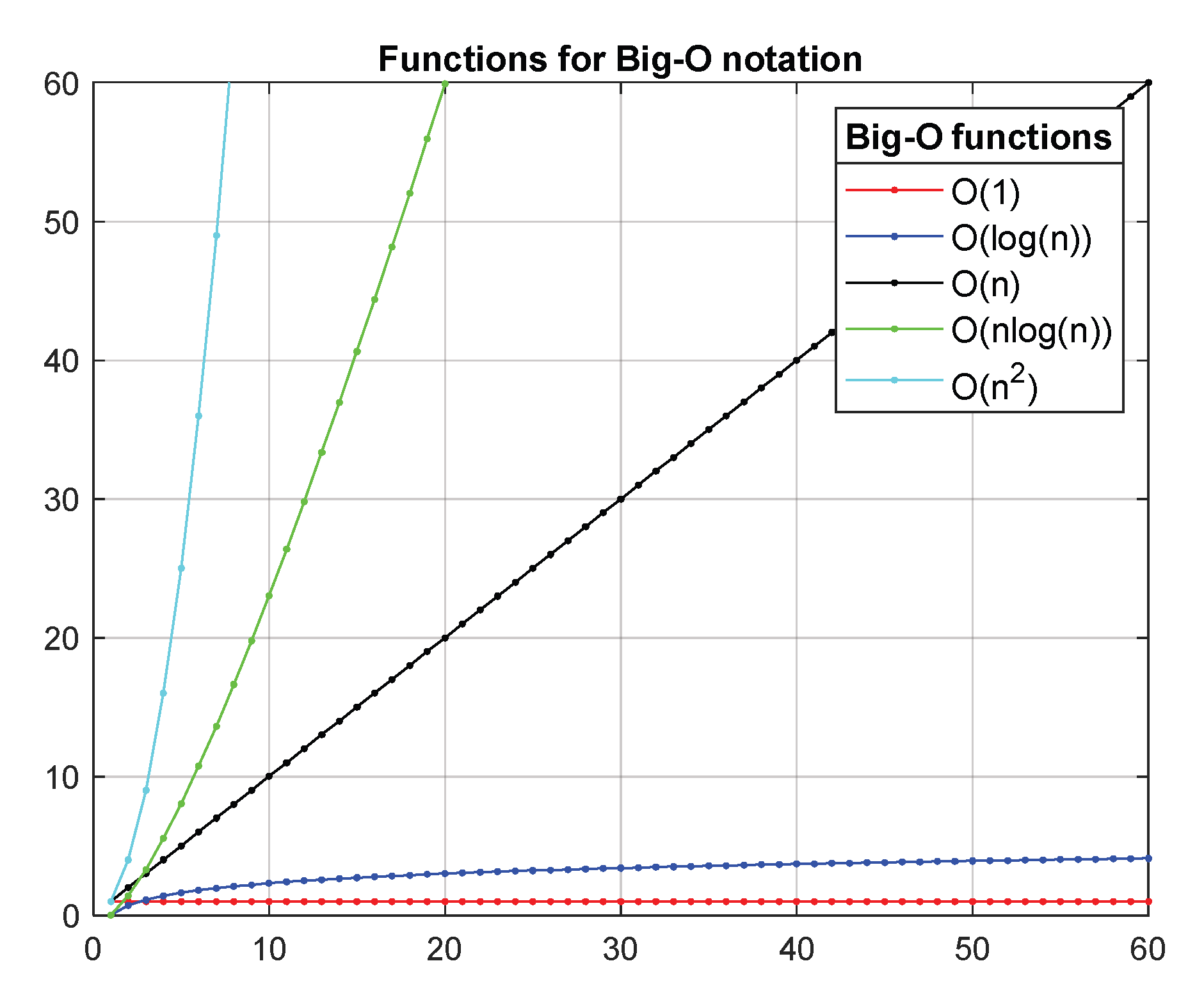
Additionally, to measure the performance of the proposed algorithm, the complexity of the algorithm is investigated in terms of time complexity. A commonly used metric for examining complexity is Big-O notation.
Figure 10 shows the commonly used functions in Big-O notation.
Firstly, we examine the time complexity of the proposed path-planning algorithm. The proposed algorithm is a combination of the A-STAR algorithm and the AHP algorithm. It plans a global path through A-STAR and moves to its destination while making decisions that meet the requirements of navigation through AHP. In the case of dynamic obstacles that appear in the process of moving to the destination, the global path is regenerated through A-STAR and decision-making is performed through AHP. First of all, since A-STAR uses heap sorting, its time complexity is given as [
27,
28]:
In addition, AHP is an algorithm that requires calculations for three objectives at the same time to evaluate each candidate and select the best candidate among candidates.
In the worst case, it moves to the destination in
steps, which is three times the node number. Therefore, the time complexity of the hybrid algorithm is given as
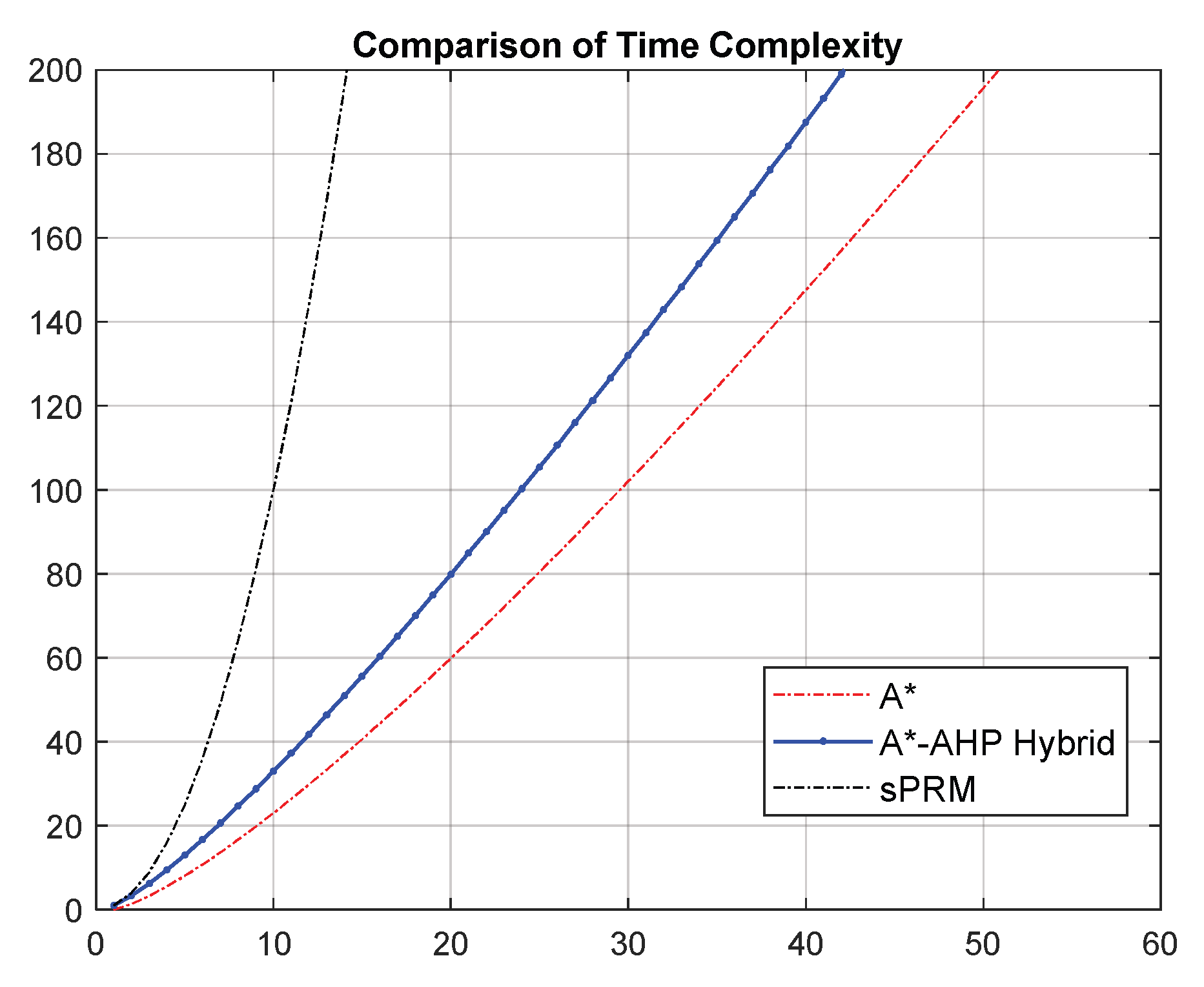
In order to compare the performance of the proposed algorithm, the time complexity of the simplified PRM (
sPRM) was also used. According to [
29], the time complexity of
sPRM is
. The comparison results are displayed in
Figure 11.
In summary, the proposed hybrid algorithm is somewhat less efficient than the conventional A-STAR in terms of time complexity but more efficient than sPRM. Although it does not outperform the existing methods, the proposed algorithm has the advantage of being able to make decisions that meet the purpose of navigation.
4. Anti-Sway Control of the Patient Transfer Robot
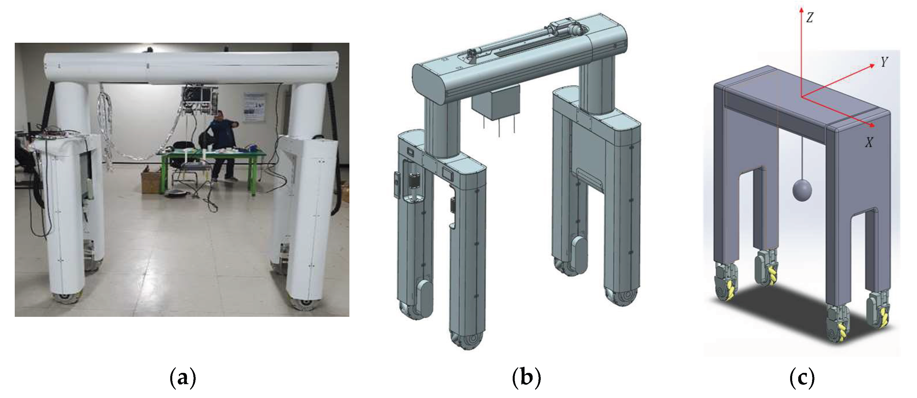
In this study, we developed an autonomous driving architecture for a robot that transports patients who cannot move on their own as shown in
Figure 12. A patient-transfer robot (PTR) is a robot that has the function of transporting a patient lying in bed to a wheelchair, toilet, or other location. In the past, caregivers transported patients by manpower, but with PTR, the risk of injury to caregivers can be reduced.
4.1. Dynamic Model of a Patient Transfer Robot
In this section, we examine the dynamics model for PTR motion control to follow the path in the higher-level controller, which is the hybrid path planner. That is, in the proposed PTR navigation, a global path is generated through A-STAR, and a local path is generated through an AHP-based algorithm. Afterward, the robot defines the generated path as a reference path and tracks the proposed path following the control method by modeling the system as a simple pendulum model. As shown in
Figure 12a, the robot used in this study has four mecanum wheels that can move in all directions as a driving mechanism. It is possible to turn in place through omnidirectional movement, which allows the robot to operate in a narrow space.
The system shown in
Figure 12a,b is a manually controlled PTR that has been developed and is expected to carry out a service for transporting patients in a medical institution through autonomous driving in the future. For this, it is essential to develop autonomous driving functions for robots. Therefore, this study focuses on path planning and motion control for autonomous driving of PTR in a hospital environment, and this section deals with motion control of a mobile platform based on the mecanum wheel. Matters to be considered in motion control for autonomous driving of the PTR are the position control of the mobile platform and the minimization of the sway of the patient riding the PTR.
That is, it is essential for PTR motion control to follow the planned path well without errors and to minimize the sway of the patient being transported. In this study, as shown in
Figure 12c, the patient is assumed to be a point mass hanging on the PTR, and the PTR system on which the patient boarded is simplified as a 3D pendulum with omnidirectional movement and can be modeled [
31,
32,
33].
where
and
are the longitudinal and lateral directional movements of the PTR.
and
is the sway angle of the patient in
and
direction.
m represent the weight of the PTR and the patient, respectively.
and
are the control inputs for driving the PTR for
x and
y directional movement.
D is the damping coefficient due to friction acting on the wheel, and
l and
g are the lengths of the cable fixing the patient and the gravitational acceleration, respectively. In order to design an anti-sway control system, the PTR in 2D plane Equations (4)–(7) are rewritten as
4.2. Patient-Transfer Robot Motion Controller Design
In this section, we propose a method to design a controller suitable for the characteristics of the system by applying the overall system dynamics, as shown in Equations (8) and (9). The dynamics model of the PTR is derived as a linear system as shown in Equations (8) and (9). Given a system model, model-based control has excellent performance. However, various uncertainties and noise of the dynamics system cannot be excluded in the process of applying the actual controller. Therefore, in this study, we propose a method applying the Kalman filter for the control of the derived model.
In this paper, a well-known LQR controller [
1,
34], the model-based control technique, is used to control the PTR system. To apply LQR control, it is necessary to obtain the equation of the state of the system to be controlled, define the performance measure of the control system, and finally solve the Riccati differential equation about the given system. As the performance measure, we utilized the following measure:
where
Q is the weighting on reference tracking error and
is the weighting on the control input. Then the feedback control law that minimizes Equation (10) is
where
K is given by
And
P is obtained from the continuous time algebraic Riccati equation:
The PTR system is modeled as a 2D movable pendulum system. It is well known that the designed controller makes the system asymptotically stable [
35]. More details are derived in [
35]. Despite the excellent performance of the LQR controller, the LQR controller is a control method that can be used when the model of the system is accurate. However, it is almost impossible to derive an accurate model due to system parameter uncertainty, sensor noise, and disturbance. Considering these aspects, this study responded to the uncertainty of the system by designing an observer to which the Kalman filter [
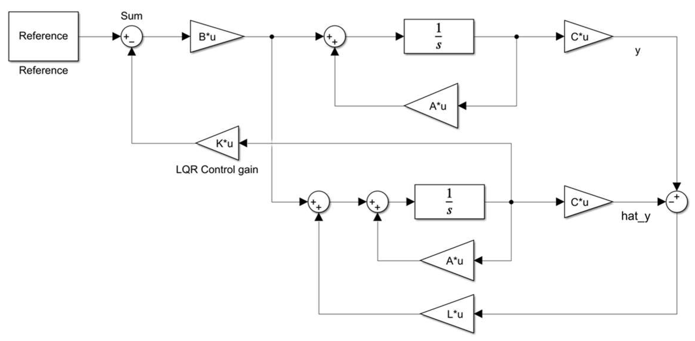
36] was applied.
Figure 13 displays the whole control structure of the PTR. In order to consider the uncertainty of the system, process noise and sensing noise were added to the previously given model as below:
where
and
denote the process noise and measurement noise, respectively.
Assuming these terms are white noise and normal distribution, the Kalman filter has the following state space model with the estimated state
,
where
is the Kalman filter gain that is obtained from the algebraic Riccati equation
where
is given.
4.3. Performance of Motion Controller
To demonstrate the performance of the proposed lower-level controller, control simulations are conducted for two scenarios: (a) Movement of the PTR to a specific point in 2D space and (b) sinusoidal movement of the PTR. In addition, sensor noise and model uncertainty are added as in the real world to demonstrate the improvement of the Kalman filter-based control. In the simulations, we primarily observed the desired trajectory tracking performance and the anti-sway capability of the suggested control scheme.
Point-to-Point Movement
The first simulation is the point-to-point movement case as shown in
Figure 14. Basically, the PTR is located in the origin
When the target position is
in 2D space, it is shown that the suggested controller successfully moves the PTR to the desired position. In the resulting figures, red, blue, and black lines represent LQR-based, Kalman filter (KF)-based, and reference with LQR for the perfect model (when the model parameters are exactly known) case, respectively. In
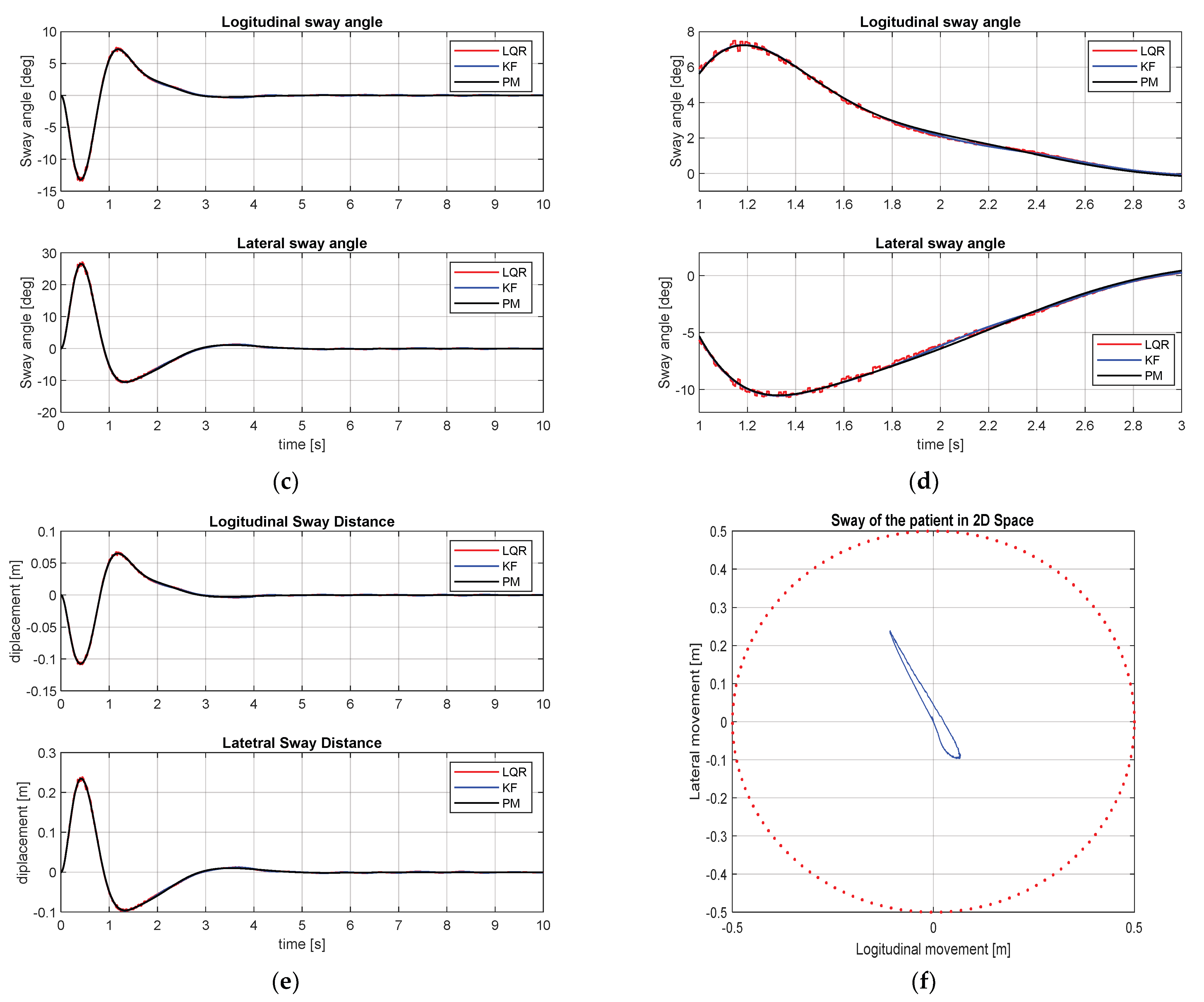
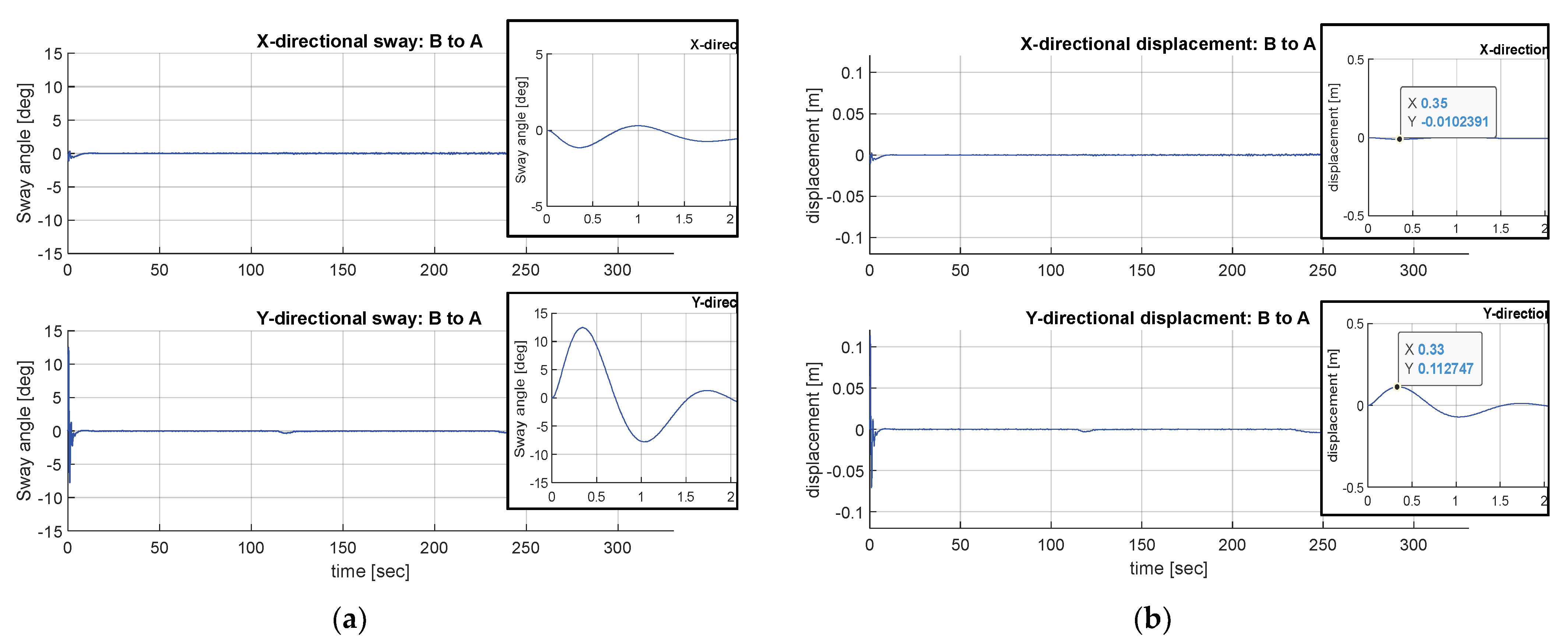
Figure 14b,d, enlarged versions of (a) and (c) are presented to show the performance of the KF-based controller better. When the sway angles are observed, in
Figure 14c,d, it is shown that a large sway angle occurs at the beginning in both directions, x and y, but it also can be observed that the sway angle converges to 0 over time.
In the 3D pendulum model, when the sway angles in the x and y directions are
and
, respectively, the displacements in each direction from PTR’s frame are as follows [
31]:
Figure 14e shows the displacement of the patient in longitudinal and lateral directions and
Figure 14f displays the movement of the patient in the
x-y plane. From the simulation results, it is observed that the movement of the patient is displayed with a blue line and shows movement in the x and y directions. The maximum displacement to each direction is 11 cm in the x-direction and 23 cm in the y-direction, respectively.
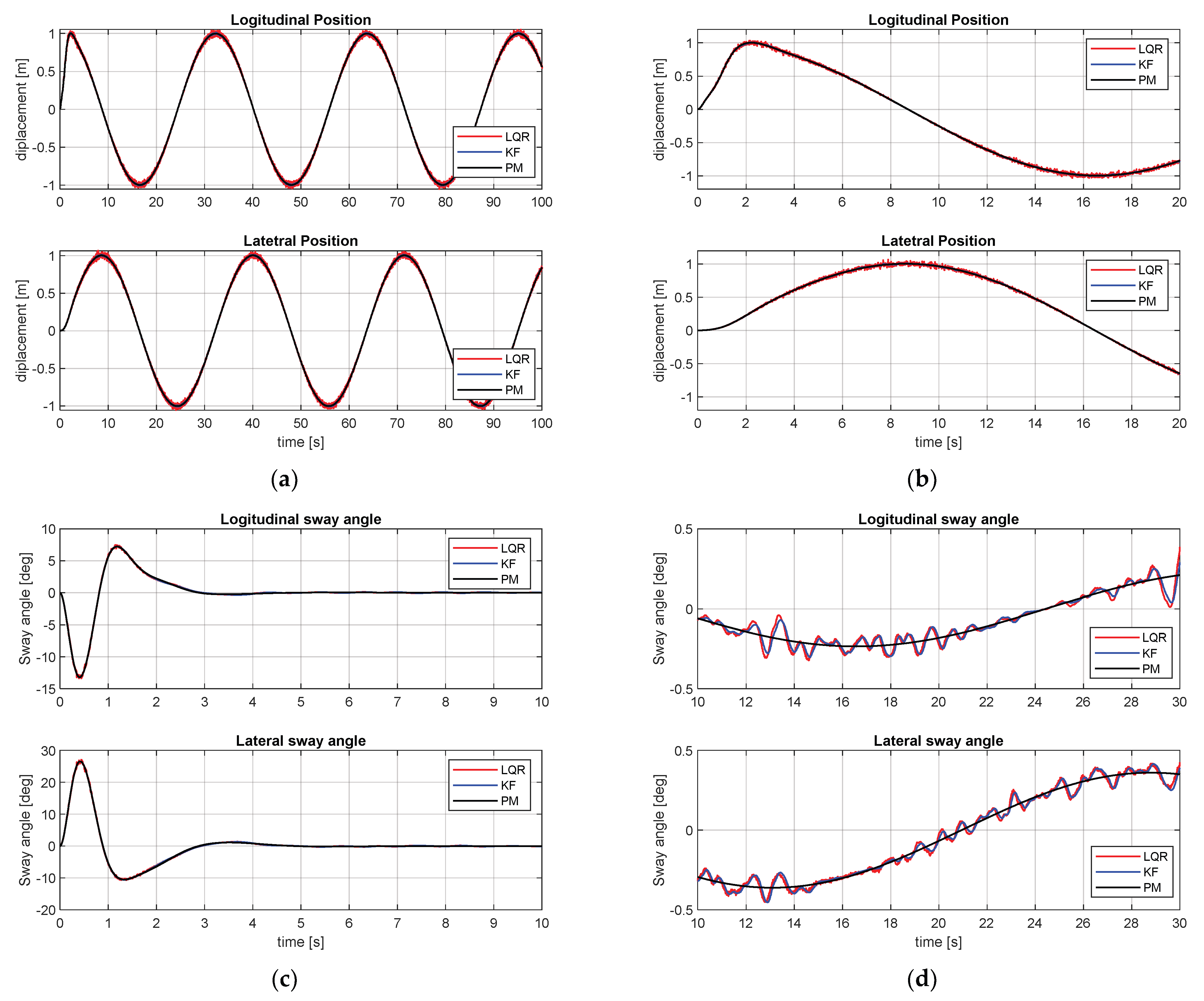
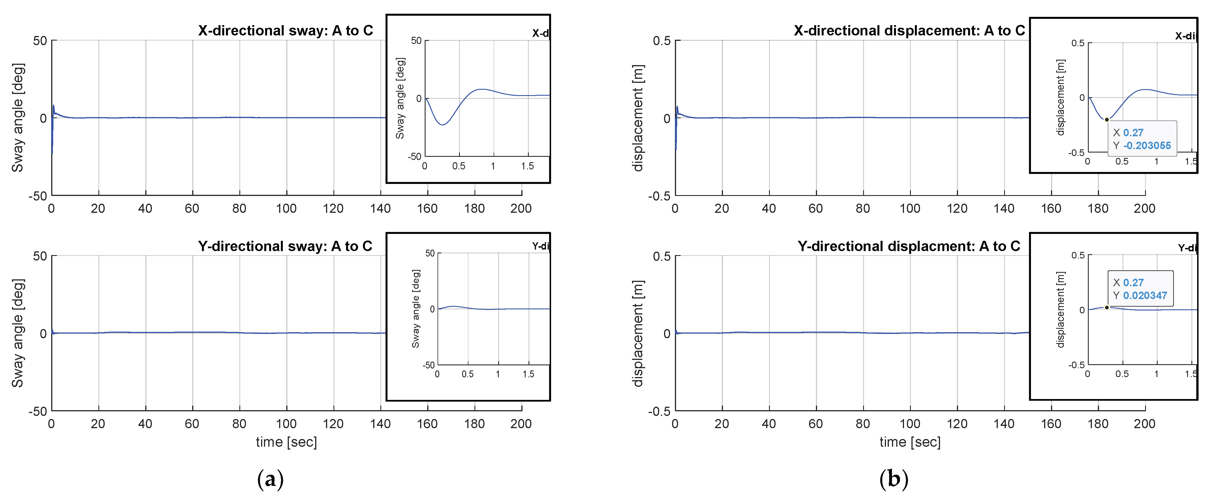
Figure 15 shows the sinusoidal movement of the PTR
and
. Eventually, the PTR movement is a circular motion. As shown in
Figure 15a,b, by means of the proposed control scheme, the PTR tracks the reference path well even in the case of following a circular path. The sway reduction performance is displayed in
Figure 15c. The patient’s sway occurs in the process of moving the PTR to follow the path from zero speed, similar to the point-to-point case. However, it shows that it follows the required path and, at the same time, reduces the sway of the patient. In other words, after the transient response condition passed, it showed the performance of transferring the patient minimizing the sway angle well. Since
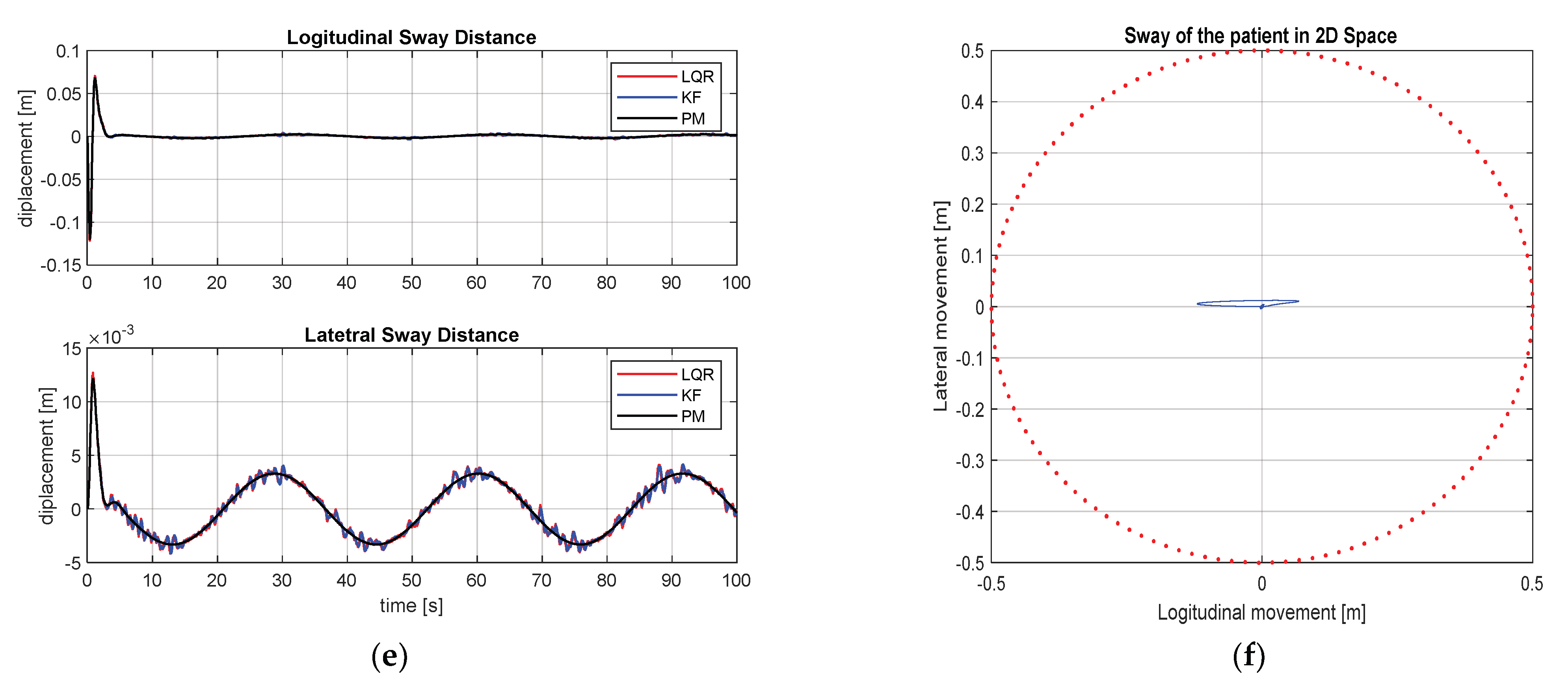
and
, which represent the patient’s way angle in x and y directions, are measured, the movement of the patient on a two-dimensional plane can be calculated by Equations (20) and (21) and are shown in
Figure 15e. In the case of sinusoidal motion, the maximum longitudinal displacement is 13 cm and the maximum displacement in the lateral direction is 13
. As a result, the performance of the system for controlling the movement of the PTR and the sway angle reduction of the patient through the LQR controller based on the Kalman filter is shown. In this Section, the performance of the proposed PTR autonomous driving module is tested in a hospital environment layout through numerical simulation.
6. Discussion
The performances of the proposed path planning and motion control method are evaluated through Matlab simulation. The performance of the path planning is confirmed by comparing the existing methods A-STAR and AHP. AHP generates the path by giving 70% weight to the shortest distance, 19% weight to safety, and 11% weight to robot rotation. In both simulation scenarios, it is confirmed that the hybrid method generates the shortest-distance performance. This result is made possible by the application of the concept of interacting with the robot’s work environment through the generation of the local path while maintaining the trend of the optimal path through global path generation. Observing the path generation results, it is also confirmed that although AHP is a local path-planning method, it shows performance quite similar to A-STAR if only the local minima can be avoided. In addition, the hybrid path-planning method shows path-shortening performances of 2.62% and 2.6%, respectively, compared to A-STAR and AHP in the first scenario, and 7.15% and 5.61% compared to each path-planning method in the second scenario.
In addition, in the motion control performance, the given path is successfully followed through the LQR controller to which the proposed KF is applied, and the patient’s sway angle decreased and finally converged to zero. However, the sway of the patient may occur via inertia caused by a sudden change in direction or rapid acceleration and deceleration of the mobile platform. Therefore, if there is no additional actuator for sway control as in the system proposed in this study, there is a limit in sway reduction control. Fortunately, the moving speed of the PTR is limited due to the patient safety issue. However, for similar applications, sway control using an additional actuator is required.
Considering the simulation results of the proposed method in an environment similar to a real hospital, this study shows two major strengths: The first is environmental robustness through the hybrid path-planning method. It is possible to move by actively responding to changes in the navigation environment. The second strength is the control performance through the application of the LQR controller to which the Kalman filter is applied. When the proposed algorithm is applied, it can be confirmed that the required path is successfully followed and the sway of the patient on board is also reduced. Through this, it shows the feasibility of applying the proposed algorithm to the PTR system in the hospital environment.
7. Conclusions
In this paper, a study is conducted on the operation of a PTR with autonomous driving technology in a medical facility. Under the assumption of a static environment, a path generated based on the map of the workspace may be optimal while the static environment is maintained. However, in order to respond to the dynamic environment in which real robots are operated, hybrid-type path planning is essential. Therefore, in this study, an efficient path-planning method is proposed through the integration of A-STAR and AHP path-planning algorithms. Furthermore, the movement control of the PTR moving in the hospital and the sway angle reduction control of the patient are conducted by the Kalman-filter-based LQR controller.
For the implementation of the proposed navigation method, the proposed algorithm is designed in three levels as introduced in
Figure 7. The first level is the global path planning to generate an optimal path based on the map for the secured workspace. The second level is local path planning, which helps to move to the final destination by actively responding to the changing environment. The final level is the motion controller to follow the predefined path and reduce the patient’s sway. In particular, for motion control, the PTR including the patient is modeled as a pendulum moving on a two-dimensional plane, and a Kalman filter is used to cope with modeling uncertainty and noise. When the hybrid path-planning level generates a path, this path is defined as the reference path of the PTR to follow. By applying the proposed KF LQR, the tracking path and sway reduction control performance are confirmed.
Nevertheless, this study has a limitation in that motion control is performed based on the mathematical model of the PTR hardware manufactured based on the project. Current hardware platforms cannot implement autonomous driving due to the absence of environmental sensors for autonomous driving. However, it is planning to develop a hardware platform capable of indoor autonomous driving through the PTR performance enhancement project. In addition, we plan to conduct hardware-based autonomous driving research by applying the algorithm developed in this study.


