

Hybrid Inspection Robot for Indoor and Outdoor Surveys

1
Department of Mechanical, Chemical and Materials Engineering (DIMCM), University of Cagliari, Via Marengo 2, 09123 Cagliari, Italy
2
Department of Civil and Mechanical Engineering (DICeM), University of Cassino and Southern Lazio, Via di Biasio 43, 03043 Cassino, Italy
*
Author to whom correspondence should be addressed.
Actuators 2023, 12(3), 108; https://doi.org/10.3390/act12030108
Submission received: 29 January 2023
/
Revised: 17 February 2023
/
Accepted: 21 February 2023
/
Published: 27 February 2023
(This article belongs to the Special Issue Actuators in 2022)
Abstract
:In this paper, simulation and experimental tests are reported for a hybrid robot being used for indoor and outdoor inspections. Automatic or tele-operated surveys can be performed by mobile robots, which represent the most efficient solution in terms of power consumption, control, robustness, and overall costs. In the context of structures and infrastructure inspection, robots must be able to move on horizontal or sloped surfaces and overpass obstacles. In this paper, the mechatronic design, simulations, and experimental activity are proposed for a hybrid robot being used for indoor and outdoor inspections, when the environmental conditions do not allow autonomous navigation. In particular, the hybrid robot is equipped with external and internal sensors to acquire information on the main structural elements, avoiding the need for experienced personnel being directly inside the inspection site, taking information from the environment and aiding the pilot to understand the best maneuvers/decisions to take. Given the current state of research and shortcomings worldwide, this paper discusses inspection robots taking into account the main issues in their use, functionality and standard systems, and how internal sensors can be set in order to improve inspection robots’ performances. On this basis, an illustrative study case is proposed.
1. Introduction
Robotics has been developed for a large variety of applications in recent decades. Mobile robots represent an interesting field of research due to their great potentialities and wide possible applications, including inspection [1,2], service [3,4], search and rescue [5,6], manufacturing [7], cleaning, remote exploration [8,9], entertainment, and agriculture [10]. In particular, the search and rescue application is related to events, such as earthquakes, hurricanes, tsunamis, typhoons, avalanches, landslides and floods. Since they may affect huge territory including buildings and infrastructures, it is important to involve robots in this type of task because a natural disaster usually affects a large number of individuals, who can survive up to about 72 h. Therefore, it is advisable to have multiple teams composed of operators and robots to maximize the search and reduce the risks for the personnel, who must interact with debris, damaged buildings, or infrastructures with serious risks of collapse.
In recent decades, the use of unmanned aerial vehicles (UAV) has enormously increased because of their features, such as rapid and cost-effective deployment, reliable wireless transmission of information, and an increased level of autonomy [11,12]. Unfortunately, the limited energy supply decreases the flight distance and operation range. The possibility of equipping UAVs with cameras and suitable sensors has allowed the use of these robots for survey and inspections [13]. Although they are actually used, in some specific circumstances, which are not a narrow area, it is still necessary to refer to unmanned ground vehicles (UGV), namely in the case of indoor inspections, confined areas, box girder bridges, pipelines, and harsh environmental conditions.
The most common type of mobile robot is the wheeled solution. It can perform a fast and robust motion on smooth surfaces, with low energy consumption and relatively easy control. It is less effective in obstacle overpassing when the dimensions are similar to or greater than the wheel radius dimension. However, for the inspection of structures and infrastructures, when the access and survey can be performed from the ground, wheeled solutions are the most used. Several prototypes and commercial solutions have been reported in the literature, such as those in [13,14].
Tracked solutions are a robust alternative, which is greatly adopted in the case of locomotion in a harsh environment [15]. The solution is mostly adopted because wheeled motion is robust, and the most efficient in terms of power consumption, overall costs, control complexity, design, and travelling speed.
Although it has inherent advantages, the presence of obstacles that inevitably could be greater than the wheel radius may occur. In these cases, the adoption of other solutions can be of great importance. Legged robots are developed for such problems; the use of multiple legs allows them to overpass obstacles, or change locomotion strategy, or gait [16,17]. The well-known limits in their application in inspection tasks are related to their extremely complex mechanical design and coordination control, high costs in purchase, and power consumption. These factors affect their possible application to inspection, although some solutions are commercially available [18,19].
In order to overcome the disadvantages of wheeled and legged robots, hybrid mobile robots have been developed by combining the design philosophy of the two locomotion types to exploit and maximize their advantages. Indeed, hybrid solutions are designed as a combination of wheels and legs, or tracks, [20,21,22,23], for a better adaptability on uneven terrains, while also considering the combination of wheels and reconfigurable legs [24]. Hybrid solutions seem to be suited to the inspection of confined areas and sites; one paradigmatic example can be box girder bridges or water distribution systems, in which there is a relatively large area to inspect that is difficult to access.
The inspection of confined areas in infrastructure can be taken into account for simulation purposes, as a possible practical application of robotics inspection, which is an area of growing interest. In fact, the general objective of an inspection robot is to use developed technology to minimize the exposure of maintenance and inspection personnel to potentially hazardous conditions by eliminating the need for them to enter the structure or infrastructure to be inspected.
Box girders are commonly adopted for large span bridges, because they possess excellent high torsional stiffness and are well suited when the self-weight of the bridge needs to be minimized. The clean lines of box girder bridges, usually with no visible external stiffening, are generally taken into account in order to provide good appearance and durability, because there are no traps for dirt and moisture. Box girders are usually adopted for footbridges, highway bridges, and railway bridges. The selection of a box girder shape usually results in relatively thin plate panels in terms of thickness to width ratio for the webs and bottom flanges, and for top flanges, in all-steel boxes. Avoidance of local buckling in compression zones and in shear requires appropriate stiffening; indeed, longitudinal stiffeners are often required. Although box sections offer high torsional stiffness, internal cross frames are usually needed to prevent distortion when one web is subject to greater shear than the other, or when one diagonal dimension across the cell increases and the other decreases.
Oil and gas/water distribution is another sector which has experienced a rapid growth in the use of autonomous or tele-operated robots. Bearing in mind that a pipeline is the major tool of transportation for that specific area, serpentine/snake robots are used [25,26,27,28] to analyze the main problems that occur, which are due to aging, corrosion, and cracks in the pipe walls [29]. Moreover, modularity and scalability for such a kind of robot is the key issue [30].
In this paper, a hybrid rover is simulated and tested for use for inspection purposes, such as those reported previously. More specifically, simulation and experimental tests will be detailed in the paper. The type and number of sensors on board have been limited to those required to improve the robot’s performance during the motion; nevertheless, the robot can perform an outdoor inspection carrying suitable instrumentation according to the information being acquired.
In this respect, the rover can be further considered as a mobile platform for integrating UAVs for advanced solutions, as proposed in [31] in which a legged mobile robot is proposed for search and rescue applications.
2. Mechatronics of the Hybrid Rover
Inspection robots use mechatronic systems, meaning the integration of mechanical systems, control, communications, and sensors. In the following section, the overall mechatronic architecture will be described.
2.1. 3D Model and Prototype
Mechanical systems are the core technology of inspection robots. Considering the application of a survey, the mechanical system should possess the following requirements.
- From the kinematic point of view, the mechanical system should be able to move and avoid and/or overpass obstacles during the survey, being able to make as many adaptations related to the environment as possible.
- The mechanical architecture must have a certain load capacity, in order that tools and equipment can be installed as needed during the application.
- The architecture should be light and compact, being easy to carry/transport/operate.
Bearing in mind the flexibility in overpassing/circumnavigating obstacles and complexity, as well as taking into account that control and lightweight structure are antagonistic features, a compromise is always the best solution. Synthesis procedures are often required when designing a desired motion, and suitable techniques are reported in [32,33]. Considering that a large number of DOFs (Degrees of Freedom), as for example in legged robots, requires a complex structure, complex control, and poor load capacity and power autonomy, a compromise among requirements is represented by a hybrid robot having three DOFs, such as the one reported in this paper.
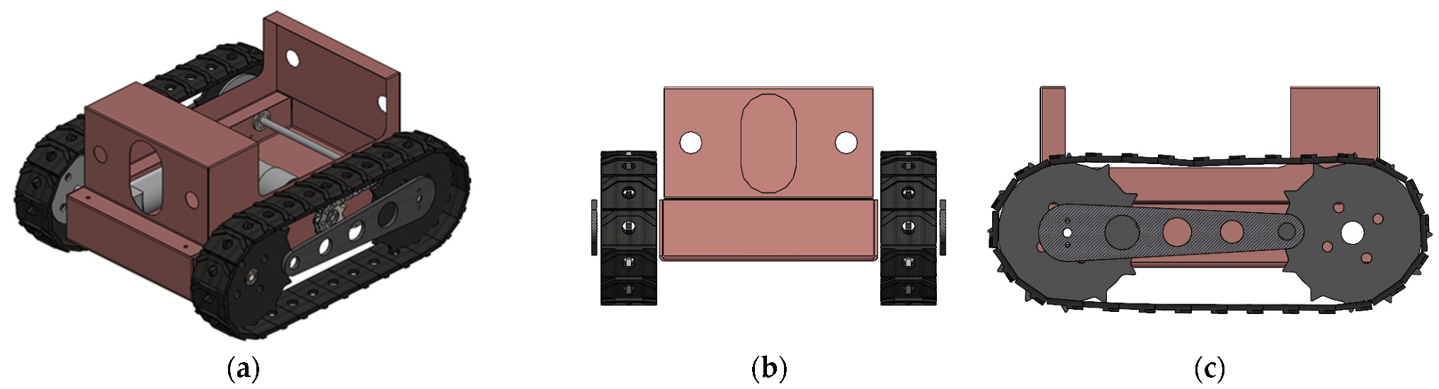
A 3D view of the robot design (named the hybrid rover) and main views are given in Figure 1. The hybrid rover is designed having tracks with two DOFs and two legs that are controlled by a single motor. As a future development of the rover design, it is planned to decouple the two legs introducing an additional motor in order to achieve asymmetrical motion and have more flexibility in overpassing obstacles. The rover has two operational modes, namely (1) a rover-like motion on flat or smooth terrain, which is the most efficient and less power-consuming type of locomotion under these environmental conditions; (2) a hybrid motion when approaching and overcoming an obstacle, where the use of the track is not sufficient for overpassing it. It is well known that if an obstacle size is greater than the radius of the track, it is not possible to overpass it. Therefore, the rover has been provided with rear or front legs for stabilization (depending on the direction of the motion) during the obstacle crossing. In particular, the legs can be used as either a propulsive element in overpassing the obstacle or for approaching it, as will be detailed in the simulation and experimental tests sections.
As it is possible to note from Figure 2, the chassis, which contains the actuation and transmission systems, together with the power supply, is the main element of the mechanical design, together with the battery pack. A chain transmission system is used to transmit the motion to the axes.
In the current design, a single motor with suitable transmission actuates the two legs, as is shown in Figure 1. The design philosophy, which has been used, is to keep the basic components, and direct drive, in order to have a robust and less expensive solution. Two independent direct-driving wheels move the tracks of the robot. The battery is located on board.
2.2. Actuation, Sensorization and Control
Inspection robots are often used in complex and harsh environmental conditions; therefore, they may have extremely high requirements for the operation of the system. The main issue, additionally from the control point of view, is the ability in designing the inspection robot, such as overpassing the largest number possible of obstacles.
Considering the great variability of obstacle types even in the same type of scenario, specific movement planning or strategies may be required to ensure the success of the operation.
Inspection robots are often used in an industrial environment. In this case, the robotic system itself may be affected by strong electric and magnetic fields. Therefore, high technical requirements for automatic navigation sensors may be required.
In terms of the current development, the application of visual navigation technology is commonly adopted, additionally because of the great variability of scenarios.
Very often, vision-based systems based on a camera and or an infrared camera must be used together with other sensors; they have been called internal [21] because they can be used to aid the control system (if autonomous navigation is pursued), or the personnel that operates the robot (if tele-operated navigation is used).
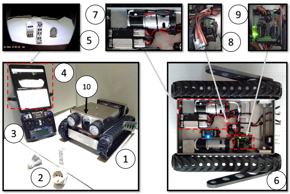
From the actuation point of view, the rover has three DOFs, two DC motors with 122 rpm and a torque = 1.47 Nm that are used for the tracks; one single motor is for the legs, allowing symmetrical motion, with characteristics of 24VDC 47 rpm and a torque = 1.96 Nm. The leg end-tips are equipped with rollers, which facilitate the operation of the robot in overpassing obstacles. The overall mechatronic scheme of the robot is shown in Figure 2.
The hybrid rover is commanded by a remote controller and the HMI interface is used for monitoring the sensors on board.
A front camera is mounted, and is used for robot vision and motion into the environment; additional sensors may be used for inspection purposes or for aiding the robot’s operations (Figure 3).
To increase the stability during negotiation with obstacles, motors are strategically placed in order to mitigate the risk of back flipping. The rover can be equipped with internal and external sensors, according to the classification reported in [21]. The internal sensor suite is detailed in Figure 3.
The internal sensor suite is devoted to aiding the pilot with navigation; if environmental conditions cause the vision system to be insufficient for understanding the environment, i.e., if the inclination of the robot chassis is close to the limit, it may be at risk of overthrowing, and therefore this information can be directly used as an alert signal. The camera is a commercial solution of the type EZVIZ C4W; it allows infrared vision, WiFi connection, a long range (up to 30 m) and full HD video streaming. The RC controller is a Spektrum DXe 6 Channel 2.4 GHz coupled with a Spektrum Receiver Mk610 2.4 GHz 6 Channel.
More information is provided in Table 2.
For many applications, such as environmental monitoring, infrastructure inspection [34], heritage management and preservation, the use of multiple sensors has been introduced in the past decade. In particular, several studies have been proposed to integrate multisource data into a unique 3D model. In fact, thermal imaging can be used for the diagnosis of energy losses in a cultural heritage through non-destructive measurement methods [35].
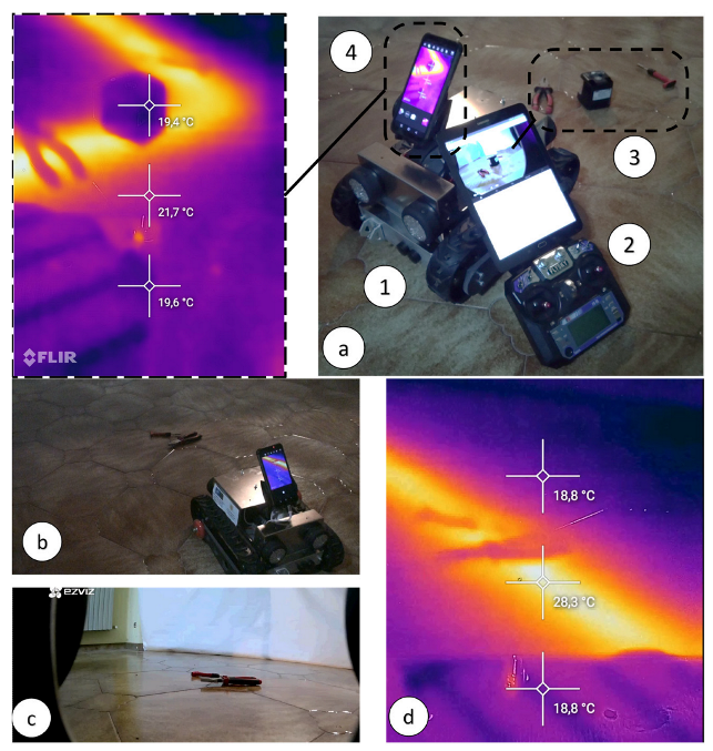
A cost-effective sensor realized by smartphones and a low-cost thermal camera has been proposed in [36] for a 3D thermal model reconstruction based on image-based modeling. According to the inspection and monitoring tasks, the so-called external sensor suite can be composed of numerous sensors, according to the type of application: it can be a camera, LIDAR, a thermal camera, gas/smoke/light/oxygen/humidity/ultrasound sensors; the choice is related to the specific variable(s) to be sensed. In many cases, image-based information is combined with thermal images to detect the spectral radiances of objects under a certain temperature based on the blackbody radiation theory. The thermal image is digitalized and records the information into a two-dimensional array.
In current applications, the overall external sensor suite constituting the onboard equipment for the hybrid rover is composed of a thermal imaging camera. The thermographic analysis, which belongs to the non-destructive tests (NDT), allows the identification of different materials returning raster images with color on the scale with a different value of the transmittance of the various materials. In civil engineering, it can be used to detect cracks or discontinuities in the pattern of the material, or inspect the electrical system. It has been chosen to limit the external sensor suite’s thermal camera, also related to the compact size of the robot, in order to maintain good maneuverability in confined spaces and energy efficiency; nevertheless, the chassis has been designed to include more sensors according to needs.
3. Simulation and Experimental Tests
Simulations are carried out to test the engineering feasibility and application of any mechatronic or automatic systems, which are also related to the main topic of the paper. Simulation is effective especially when the large dimensions of the systems do not allow the realization of prototypes, as in the case reported in [40,41].
In the context of testing robot performances and preparing robust and repeatable tests to be done both numerically and experimentally, the concept of the stepfield pallet can be introduced [42]. This method is important for revealing unexpected inconsistencies between the simulation and real behavior of the mechatronic system because it is repeatable and deterministic, and one can then identify the problem with the physics of the model [43]. Moreover, simulation parameters can be compared with physical parameters, i.e., to (I) verify the correctness of the model; (II) use the simulation to obtain results in different scenarios; (III) use the real data together with simulation models to create alert systems in order to correct the operation of the system, as will be reported in the following sections. Once the 3D models have been verified, experienced personnel in charge of operating the system can develop the software and integrate it into a physical system.
One of the most used test methods for mobile robotics is the stepfield pallet, which has been introduced for testing the mobility performances of the robots.
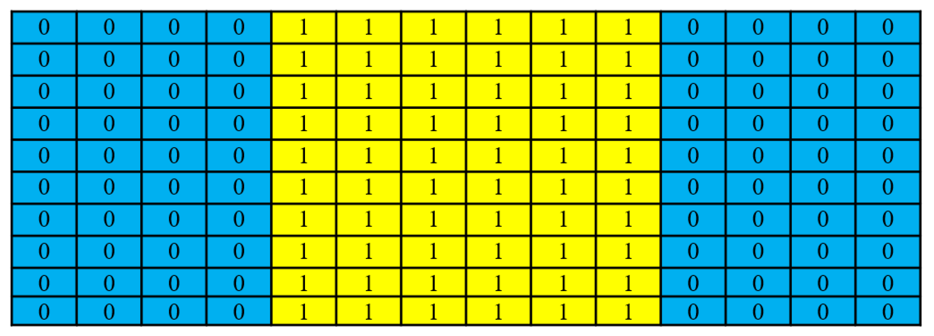
Mobile robots must negotiate specific obstacles on a path, or the total distance traversed, to give a measure of the robot’s mobility performance. Stepfield pallets are made of an array of wooden cubes or bricks differently arranged according to the type, the size and the kind of performance to be tested. The idea is to create a repeatable terrain. The stepfield pallets are repeatable surface topologies with different levels of ”aggressiveness” [43]. The realization of the stepfield pallet in Figure 5 allows the repetition of the test reported in Figure 6 experimentally, as is shown in the snapshots in Figure 7.
Stepfield pallets can be realized randomly or with regular grids or steps, according to the application. In this context, we created a symmetrical step filed pallet, because the main purpose of its use is to verify the 3D model of the robot and create a set of alarm signals, according to the on-board sensors.
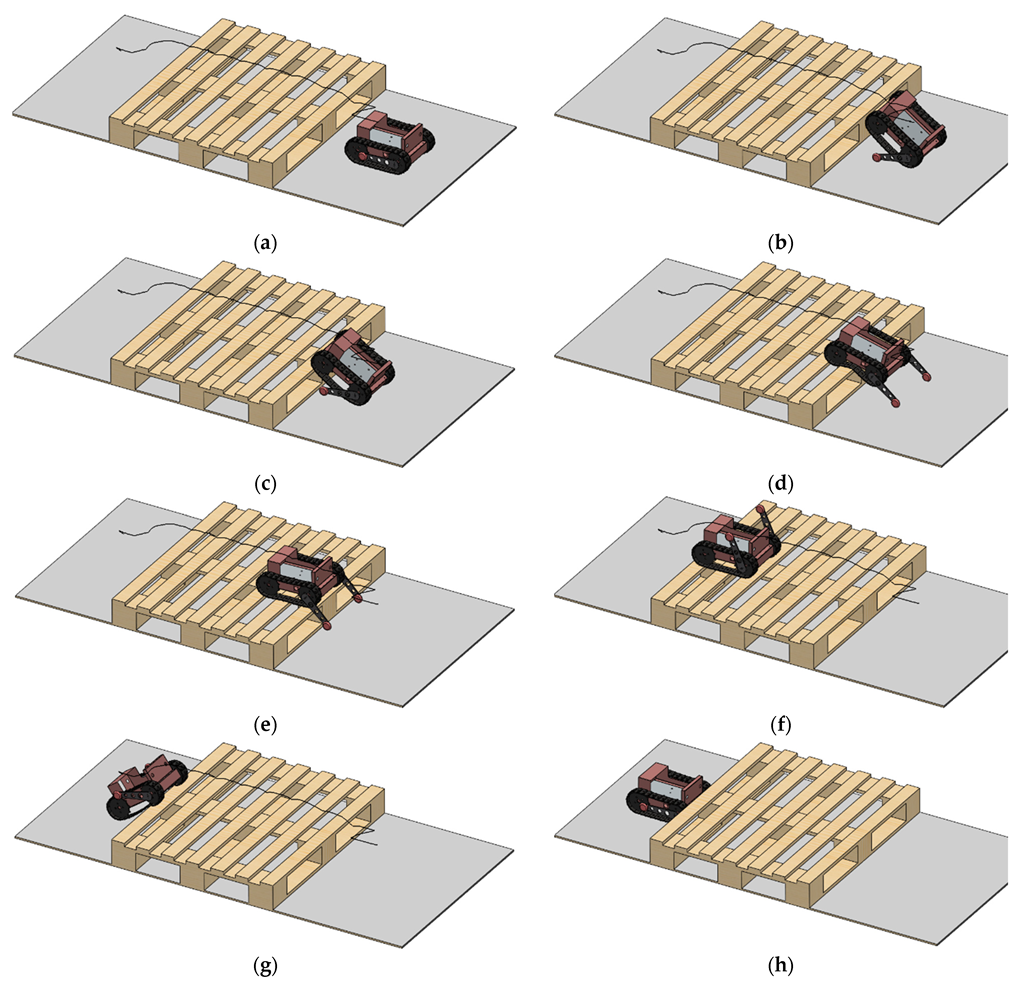
The dimensions of the stepfield pallet are 0 = ground level, 1 = 150 mm. The box is 1200 mm × 100 mm with an overall length of 1000 mm. The numerical results report a simulated motion overpassing the obstacle, which is evidently higher than the track’s height; therefore, it is obliged to use its legs for overpassing the obstacle, which may be normal during the survey. The simulations show the robot overpassing the obstacle, which is representative of rails, the internal stiffeners, or any other structural element that can be included in the context of a structure inspection. In particular, Figure 6a shows the robot approaching the obstacles: in (b) the legs are employed to raise the obstacle; in (c) tracks start the contact with the obstacle. In Figure 6d, the hybrid robot climbs the obstacle until (e) when the operation is complete. The robot moves on the stepfield pallet until Figure 6f when the descending operation occurs at (g) to end at (h).
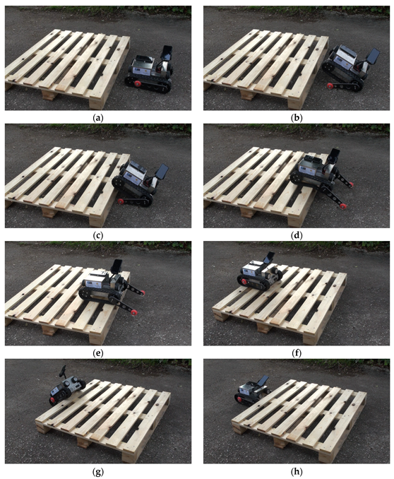
The same operation has been tested experimentally, as reported in Figure 7.
Simulation tools are very effective when dealing with large-scale systems being designed and tested to operate in an urban environment, as is reported in [39,40]. Simulations are therefore very important to verify the robot’s capabilities, additionally in terms of motion and carriage of suitable sensors [44]. In addition, they are useful tools for overthrowing verification. Referring to the experimental tests, the robot has been equipped with an internal sensor suite, but not with a thermal camera, because the main issue reported here is not related to the experimental activity, but the use of internal sensor suite for obtaining additional information other than vision. Indeed, the robot is moved to climb and overpass the stepfield pallet described in Figure 5. Legs and tracks are moved in an almost identical manner in order to replicate the motion, as can be appreciated by considering the motion sequence in Figure 6.
4. Discussion about the Results
The development of an on-site application of automation and robotics for inspection is related to the concept of smart buildings, smart sensors, and cyber-physical systems. In the future, the use of robotic maintenance can reduce energy consumption by up to 95% and carbon dioxide emissions by replacing helicopters with suspended robots for inspecting transmission lines [45]. The environmental sustainability of construction logistics and waste management can also benefit from robotic technologies, e.g., by using automated systems able to process on-site material and in that way automate the construction of entire utility structures, especially in places that are potentially dangerous or difficult to access [46]. Realistic on-site applications of robotics and automation still face some limitations, mostly related to implementation costs, inflexibility and technological immaturity [46]. This includes measurement accuracy, sensor miniaturization, wireless communication, smart sensor availability, and long-term powering for durability issues. This is quite important for structural health monitoring, as for example for the detection of earthquakes [39].
The introduction of Cyber-Physical Systems (CPS) has raised issues related to security and stability, which may affect automated solutions. Without proper experimental validation of the CPS, they are of no use and can potentially cause critical damage to the infrastructure rather than benefits. Additionally, the lack of a supporting infrastructure such as ICT, especially in harsh environments or remote areas, is also a great limitation on real-time monitoring. All these factors make the introduction of robotics and automation in the inspection of structures and infrastructures only apparently easy to use and manage, while hiding drawbacks such as high purchase and maintenance costs, significant financial commitment for data management and processing to turn raw data into usable information, or the possibility of managing the system in a complex scenario.
The last is the motivation of the research proposed here; it turns out to be useful having a realistic model to be used to manage the real prototype, helping the end-user not only to understand the signals and measurements of the internal sensor suite, but also to anticipate possible failures using these measurements or signals as alerts. In this respect, a realistic dynamic model of a rover was developed in [47] for planetary exploration. Data available from sensors can be used for autonomous navigation as well as for the agriculture sector, as was reported in [48].
In order to validate the 3D model proposed in the previous section, experimental activity was carried out replicating the same scenario and recording information by the sensors on board. In particular, as representative of the results, the COG (center of gravity) velocity is displayed in Figure 8 with the eight phases highlighted and schematically represented, as follows
- Phase 1: 0 ÷ 4 s, approach to the obstacle, the tracks only are active;
- Phase 2: 4 ÷ 9 s, the legs rotate clockwise to lift the robot;
- Phase 3: 9 ÷ 13 s, the robot moves forward until the tracks begin contact with the pallet;
- Phase 4; 13 ÷ 24 s, the legs rotate counterclockwise to lift the robot. The robot lifts and move a little bit forward;
- Phase 5; 24 ÷ 31.5 s, the robot advances with its legs lowered and climbs completely onto the pallet;
- Phase 6; 31 ÷ 36 s, the robot negotiates with the five slopes that can be recognized by the five peaks;
- Phase 7; 36 ÷ 38 s, the robot moves forward and descends from the pallet;
- Phase 8; 38 ÷ 39.5 s, the robot descends completely from the pallet.
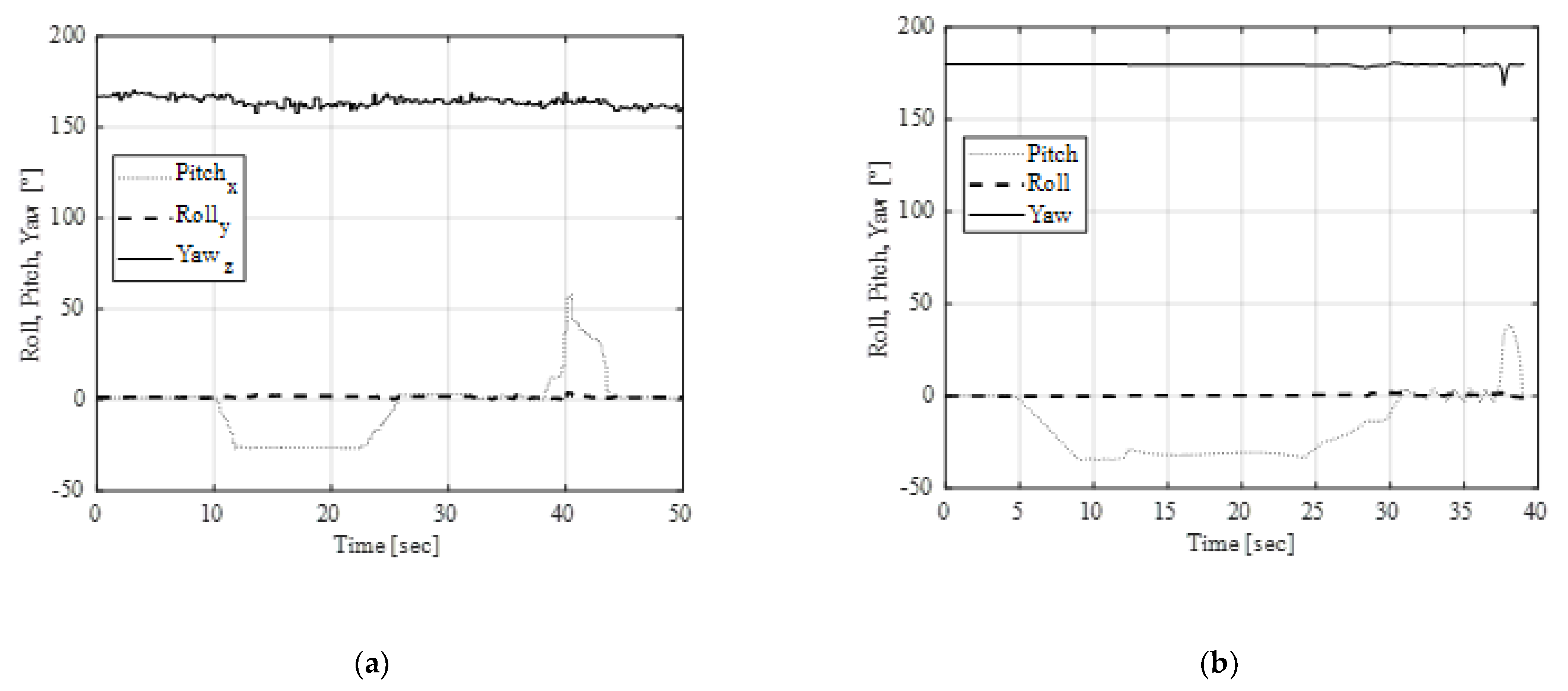
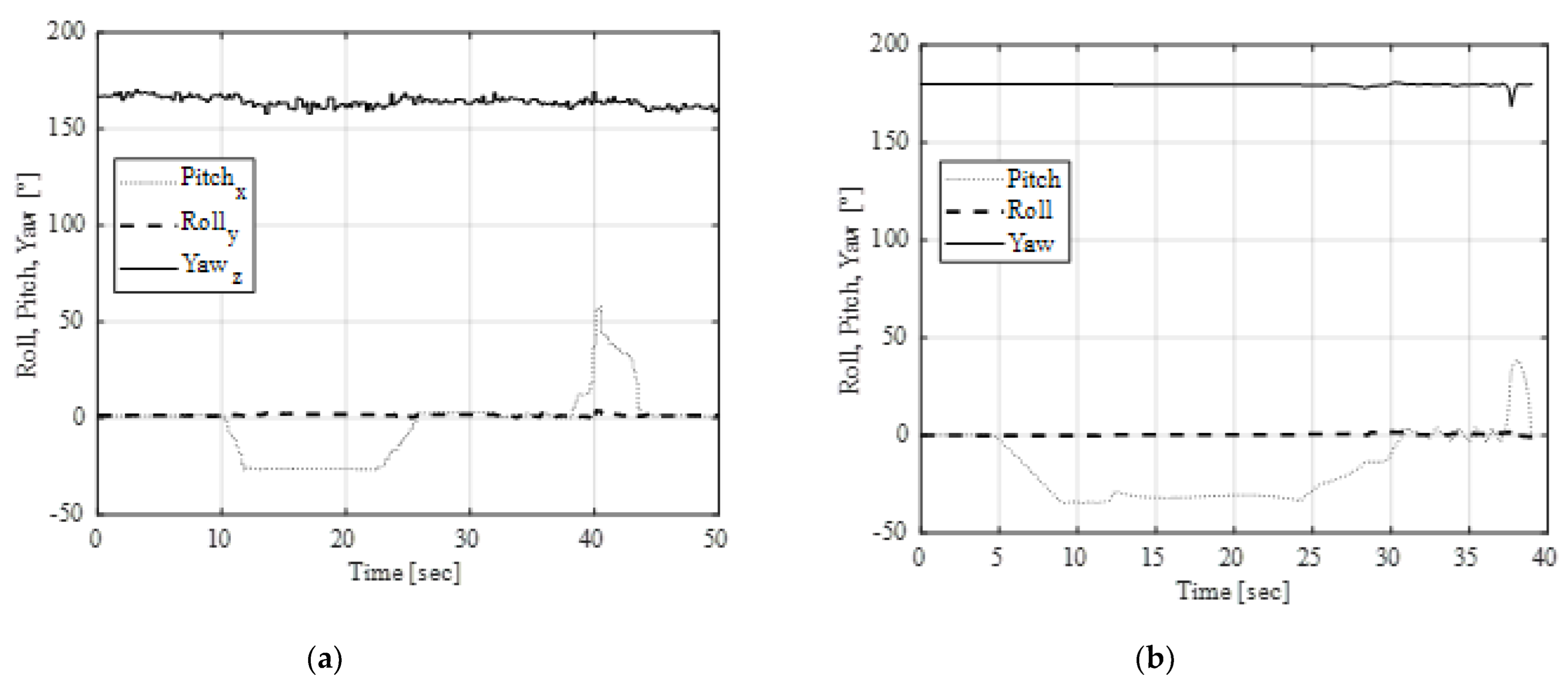
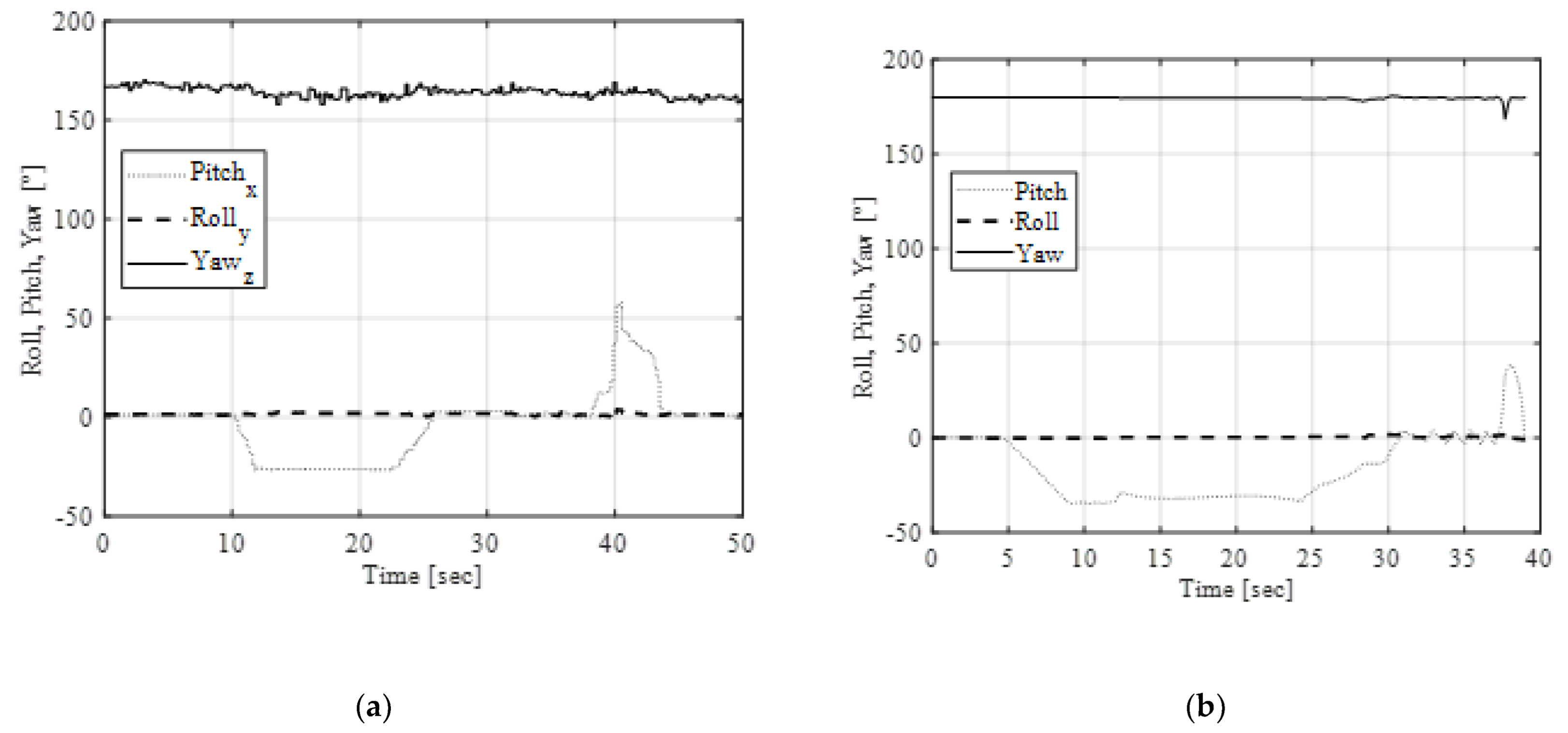
According to the eight phases, also visible in Figure 7 and Figure 8, the numerical vs. experimental tests are given in Figure 9, Figure 10 and Figure 11. Of course, it is possible to obtain more data from simulation, but we have included only the data that can be compared with experimental results. In particular, Figure 9 reports the roll, pitch, and yaw of the robot; the comparison shows a good overlapping of the results, taking into consideration that the robot is tele-operated and not preprogrammed. In Figure 10, the linear acceleration can be useful, together with the inclination of the robot in Figure 9, to detect the presence of obstacles to create alert functions.
It is worth noting that the different behavior experienced during phase 6 is related to the negotiation with the five slopes on the pallet, which gives differences related to the tension/slackness of the tracks during the motion and results in different accelerations.
This fact additionally illustrates the need to have other information than vision only, and multiple sources, such as inclination sensors, acceleration, and velocity, as reported in Figure 11. The information obtained by the internal and external sensor suite can be used to build an alert system, giving an HMI such as the one depicted in Figure 12.
The use of internal sensor suite is the validation of the 3D model of the robot, and the creation of suitable mathematical models for allowing the pilot of the mobile robot—in the case of respective teleoperation—or robot controller algorithm—in the case of autonomous behavior—to improve the performances. The method and used approach can be adopted for mobile robots in similar situations; types of obstacles and data from sensors must be handled with a similar approach.
5. Conclusions
In this paper, we proposed the simulation and experimental tests of a hybrid robot being used for structure and infrastructure inspection. In particular, a suitable 3D multibody model permits the development of the simulation of a realistic scenario and operation planning for a mechatronic survey. Comparison between simulations and experimental tests shows a good behavior of the robot in allowing the planning of operations that are more complex. The main contribution of the research proposed here is to develop and test realistic models being used to manage the real prototype, acting as a digital twin of the real system, helping the end-user not only to understand the signals and measurements of the internal sensor suite, but additionally anticipating possible failures using these measurements or signals as alerts, which may be deployed in the future to build a control system for mitigating failures The ongoing work with the proposed robot involves the integration of the sensor suite with thermal cameras and experimental tests on the real site of interest.
Author Contributions
Conceptualization, P.R. and E.O.; methodology, E.O.; software, P.R.; validation, P.R.; formal analysis, E.O.; investigation, P.R. and E.O.; resources, E.O. data curation, P.R. writing—original draft preparation, P.R; writing—review and editing, E.O.; visualization, P.R.; supervision, P.R.; project administration, E.O.; funding acquisition, E.O. All authors have read and agreed to the published version of the manuscript.
Funding
This paper is part of a project that has received funding from NATO, Science for Peace and Security Programme Multi-Year Project Application, G5924-“IRIS—Inspection and security by Robots interacting with Infrastructure digital twinS”.
Data Availability Statement
Data is contained within the article.
Conflicts of Interest
The authors declare no conflict of interest.
References
- Bruzzone, L.; Baggetta, M.; Nodehi, S.E.; Bilancia, P.; Fanghella, P. Functional Design of a Hybrid Leg-Wheel-Track Ground Mobile Robot. Machines 2021, 9, 10. [Google Scholar] [CrossRef]
- Muthugala, M.A.V.J.; Palanisamy, P.; Samarakoon, S.M.B.P.; Padmanabha, S.G.A.; Elara, M.R.; Terntzer, D.N. Raptor: A Design of a Drain Inspection Robot. Sensors 2021, 21, 5742. [Google Scholar] [CrossRef] [PubMed]
- Sprenger, M.; Mettler, T. Service Robots. Bus. Inf. Syst. Eng. 2015, 57, 271–274. [Google Scholar] [CrossRef]
- Gonzalez-Aguirre, J.A.; Osorio-Oliveros, R.; Rodríguez-Hernández, K.L.; Lizárraga-Iturralde, J.; Morales Menendez, R.; Ramírez-Mendoza, R.A.; Ramírez-Moreno, M.A.; Lozoya-Santos, J.d.J. Service Robots: Trends and Technology. Appl. Sci. 2021, 11, 10702. [Google Scholar] [CrossRef]
- Sibanyoni, S.V.; Ramotsoela, D.T.; Silva, B.J.; Hancke, G.P. A 2-D Acoustic Source Localization System for Drones in Search and Rescue Missions. IEEE Sens. J. 2019, 19, 332–341. [Google Scholar] [CrossRef]
- Habibian, S.; Dadvar, M.; Peykari, B.; Hosseini, A.; Salehzadeh, M.H.; Hosseini, A.H.; Najafi, F. Design and implementation of a maxi-sized mobile robot (Karo) for rescue missions. Robomech J. 2021, 8, 1. [Google Scholar] [CrossRef]
- Sharifzadeh, S.; Biro, I.; Lohse, N.; Kinnell, P. Abnormality detection strategies for surface inspection using robot mounted laser scanners. Mechatronics 2018, 51, 59–74. [Google Scholar] [CrossRef]
- Bellingham, J.G.; Rajan, K. Robotics in Remote and Hostile Environments. Science 2007, 318, 1098. [Google Scholar] [CrossRef] [Green Version]
- Shapovalov, D.; Pereira, G.A.S. Tangle-Free Exploration with a Tethered Mobile Robot. Remote Sens. 2020, 12, 3858. [Google Scholar] [CrossRef]
- Acaccia, G.M.; Michelini, R.C.; Molfino, R.M.; Razzoli, R.P. Mobile robots in greenhouse cultivation: Inspection and treatment of plants. In Proceedings of the ASER 2003, 1st International Workshop on Advances in Service Robotics, Bardolino, Italy, 2003. [Google Scholar]
- Amici, C.; Ceresoli, F.; Saponi, M.; Pasetti, M.; Zanoni, S.; Borboni, A.; Tiboni, M.; Faglia, R. Experimental Characterization of an Electrical Propulsion Unit for Service UAVs. In Proceedings of I4SDG Workshop 2021: IFToMM for Sustainable Development Goals; Springer International Publishing: Midtown Manhattan, NY, USA, 2022; Volume 108 MMS, pp. 307–314. [Google Scholar] [CrossRef]
- Amici, C.; Ceresoli, F.; Pasetti, M.; Saponi, M.; Tiboni, M.; Zanoni, S. Review of propulsion system design strategies for unmanned aerial vehicles. Appl. Sci. 2021, 11, 5209. [Google Scholar] [CrossRef]
- SmpRobotics. Available online: https://smprobotics.com/ (accessed on 12 January 2023).
- Vong, C.H.; Ryan, K.; Chung, H. Trajectory tracking control of quadcopters under tunnel effects. Mechatronics 2021, 78, 102628. [Google Scholar] [CrossRef]
- Pelliccio, A.; Ottaviano, E.; Rea, P. Digital and Mechatronic Technologies Applied to the Survey of Brownfields. In Chapter 27 in Handbook of Research on Emerging Digital Tools for Architectural Surveying, Modeling, and Representation; Brusaporci, S., IGI Global, Eds.; IGI Global: Hershey, PA, USA, 2015; pp. 813–829. ISBN 978-146668380-8. [Google Scholar] [CrossRef]
- Figliolini, G.; Rea, P.; Conte, M. Mechanical design of a novel biped climbing and walking robot. CISM International Centre for Mechanical Sciences. Courses Lect. 2010, 524, 199–206. [Google Scholar]
- Ramezani, M.; Brandao, M.; Casseau, B.; Havoutis, I.; Fallon, M. Legged Robots for Autonomous Inspection and Monitoring of Offshore Assets. In Proceedings of the Paper Presented at the Offshore Technology Conference, Houston, TX, USA, 4 May 2020. [Google Scholar] [CrossRef]
- ANYbotics. Available online: https://www.anybotics.com/ (accessed on 5 January 2023).
- Boston Dynamics. Available online: https://www.bostondynamics.com/products/spot (accessed on 8 January 2023).
- Ottaviano, E.; Rea, P.; Castelli, G. THROO: A Tracked Hybrid Rover to Overpass Obstacles. Adv. Robot. 2014, 28, 683–694. [Google Scholar] [CrossRef]
- Rea, P.; Ottaviano, E. Design and Development of an Inspection Robotic System for Indoor Applications. Robot. Comput. Integr. Manuf. 2018, 49, 143–151. [Google Scholar] [CrossRef]
- Rea, P.; Pelliccio, A.; Ottaviano, E.; Saccucci, M. The Heritage Management and Preservation Using the Mechatronic Survey. Int. J. Archit. Herit. 2017, 11, 1121–1132. [Google Scholar] [CrossRef]
- Ottaviano, E.; Rea, P. Design and operation of a 2-DOF leg-wheel hybrid robot. Robotica 2013, 31, 1319–1325. [Google Scholar] [CrossRef]
- Ngo, H.Q.T.; Cao Tri, H.; Tu, N.T.; Bao, D.N.T.; Anh Duy, P.L.; Phat, K.M.; Duy, T.A.; Tin, N.T. Design of reconfigurable mechanism for underactuated robot in the grounded applications. Cogent Eng. 2022, 9, 1. [Google Scholar] [CrossRef]
- Granosik, G.; Borenstein, J.; Hansen, M.G. Serpentine Robots for Industrial Inspection and Surveillance. In Industrial Robotics—Programming, Simulation and Applications; Kin Huat, L., Ed.; Literatur Verlag: Munich, Germany, 2007; pp. 633–662. [Google Scholar]
- Maurtua, I.; Susperregi, L.; Fernández, A.; Tubío, C.; Perez, C.; Rodríguez, J.; Felsch, T.; Ghrissi, M. MAINBOT-mobile robots for inspection and maintenance in extensive industrial plants. Energy Procedia 2014, 49, 1810–1819. [Google Scholar] [CrossRef] [Green Version]
- Van Den Bos, B.; Strand, J.; Mallion, A.; Oetiker, M.; Schler, A.; Black, T.; Potnis, P. Robotic Inspection Solutions for Petrochemical Pressure Vessels, developed and tested in the PETROBOT project. In Proceedings of the 19th World Conference on Non-Destructive Testing, Munich, Germany, 13–17 June 2016; p. 20121. [Google Scholar]
- Gargade, A.; Ohol, S. Design and Development of In-Pipe Inspection Robot. Am. Int. J. Res. Sci. Technol. Eng. Math. 2016, 15, 104–109. [Google Scholar]
- Wickramanayake, S.; Thiyagarajan, K.; Kodagoda, S.; Piyathilaka, L. Ultrasonic thickness measuring in-pipe robot for real-time non-destructive evaluation of polymeric spray linings in drinking water pipe infrastructure. Mechatronics 2022, 88, 102913. [Google Scholar] [CrossRef]
- Canali, C.; Pistone, A.; Guardiani, P.; Ludovico, D.; Leggieri, S.; Gloriani, C.; Caldwell, D.G. Inspection Robotics for Harsh Environments. Industrial Applications and Infrastructures; I-RIM: Genova, Italy, 2020. [Google Scholar]
- Lindqvist, B.; Karlsson, S.; Koval, A.; Tevetzidis, I.; Haluška, J.; Kanellakis, C.; Agha-mohammadi, A.; Nikolakopoulos, G. Multimodality robotic systems: Integrated combined legged-aerial mobility for subterranean search-and-rescue. Robot. Auton. Syst. 2022, 154, 104134. [Google Scholar] [CrossRef]
- Figliolini, G.; Rea, P. Effects of the design parameters on the synthesis of Geneva mechanisms. Proc. Inst. Mech. Engineers. PART C J. Mech. Eng. Sci. 2012, 227, 2000–2009. [Google Scholar] [CrossRef]
- Rea, P.; Ottaviano, E. Functional Design for Customizing Sit-To-Stand Assisting Devices. J. Bionic Eng. 2018, 15, 83–93. [Google Scholar] [CrossRef]
- Valigi, M.C.; Logozzo, S.; Meli, E.; Rindi, A. New Instrumented Trolleys and A Procedure for Automatic 3D Optical Inspection of Railways. Sensors 2020, 20, 2927. [Google Scholar] [CrossRef]
- Paziewska, J.; Rzonca, A. Integration of Thermal and RGB Data Obtained by Means of a Drone for Interdisciplinary Inventory. Energies 2022, 15, 4971. [Google Scholar] [CrossRef]
- Yang, M.-D.; Su, T.-C.; Lin, H.-Y. Fusion of Infrared Thermal Image and Visible Image for 3D Thermal Model Reconstruction Using Smartphone Sensors. Sensors 2018, 18, 2003. [Google Scholar] [CrossRef] [Green Version]
- Figliolini, G.; Rea, P. Mechatronic Design and Experimental Validation of a Novel Robotic Hand. Ind. Robot. Int. J. 2014, 41, 98–108. [Google Scholar] [CrossRef]
- Sorli, M.; Figliolini, G.; Pastorelli, S.; Rea, P. Experimental identification and validation of a pneumatic positioning servo-system. In Power Transmission and Motion Control PTMC 2005; John Wiley & Sons, Ltd.: Bath, UK, 2005; pp. 365–378. [Google Scholar]
- Ceccarelli, M.; Ottaviano, E.; Galvagno, M. A 3-DOF Parallel Manipulator as Earthquake Motion Simulator. In Proceedings of the 7th International Conference on Control, Automation, Robotics and Vision, ICARCV 2002, Singapore, 2–5 December 2002; pp. 944–949. [Google Scholar]
- Ottaviano, E.; Ceccarelli, M.; De Ciantis, M. A 4-4 Cable-Based Parallel Manipulator for an Application in Hospital Environment. In Proceedings of the 15th Mediterranean Conference on Control and Automation—MED07, Athens, Greece, 27–29 June 2007. [Google Scholar]
- Castelli, G.; Ottaviano, E.; Rea, P. A Cartesian Cable-Suspended Robot for improving end-users’ mobility in an urban environment. Robot. Comput. Integr. Manuf. 2014, 30, 335–343. [Google Scholar] [CrossRef]
- Jacoff, A.; Messina, E.; Weiss, B.A.; Tadokoro, S.; Nakagawa, Y. Test Arenas and Performance Metrics for Urban Search and Rescue Robots. In Proceedings of the IEEE International Conference on Intelligent Robots and Systems, Las Vegas, NV, USA; 2003; Volume 4, pp. 3396–3403. [Google Scholar]
- Jacoff, A.; Downs, A.; Virts, A.; Messina, E. Stepfield pallets: Repeatable terrain for evaluating robot mobility. In Proceedings of the Performance Metrics for Intelligent Systems Workshop (PerMIS), Gaithersburg, MD, USA, 19–21 August 2008; pp. 29–34. [Google Scholar] [CrossRef]
- Gonzalez-Rodriguez, A.; Castillo-Garcia, F.J.; Ottaviano, E.; Rea, P.; Gonzalez-Rodriguez, A.G. On the effects of the design of cable-Driven robots on kinematics and dynamics models accuracy. Mechatronics 2017, 43, 18–27. [Google Scholar] [CrossRef]
- Nagarajan, B.; Li, Y.; Sun, Z.Y.; Qin, R.W. A routing algorithm for inspecting grid transmission system using suspended robot: Enhancing cost-effective and energy efficient infrastructure maintenance. J. Clean. Prod. 2019, 219, 622–638. [Google Scholar] [CrossRef]
- Hoeft, M.; Pieper, M.; Eriksson, K.; Bargstädt, H.-J. Toward Life Cycle Sustainability in Infrastructure: The Role of Automation and Robotics in PPP Projects. Sustainability 2021, 13, 3779. [Google Scholar] [CrossRef]
- Yang, H.; Ding, L.; Gao, H.; Wang, Z.; Lan, Q.; Liu, G.; Liu, Z.; Li, W.; Deng, Z. High-Fidelity Dynamic Modeling and Simulation of Planetary Rovers Using Single-Input-Multi-Output Joints With Terrain Property Mapping. IEEE Trans. Robot. 2022, 38, 3238–3258. [Google Scholar] [CrossRef]
- Mejia, G.; Montes de Oca, A.; Flores, G. Strawberry localization in a ridge planting with an autonomous rover. Eng. Appl. Artif. Intell. 2023, 119, 105810. [Google Scholar] [CrossRef]
Figure 1.
3D model of the hybrid robot: (a) 3D view; (b) front view; (c) side view.

Figure 2.
Overall scheme of the mechatronic system: (1) robot; (2) objects on the path; (3) RC controller; (4) HMI interface; (5) view of the camera on board; (6) internal view of the robot-control boards; (7) zoom-in view of the actuator and lithium battery pack; (8) Spektrum Receiver Mk610; (9) electronic board for motor control; (10) front camera for vision.

Figure 3.
Scheme for the internal sensor suite composed of a front camera, led lights, an accelerometer, a linear accelerometer, a sensor for orientation and rotation, a gyroscope, and a gravity sensor. The reference system is given in the scheme.
Figure 3.
Scheme for the internal sensor suite composed of a front camera, led lights, an accelerometer, a linear accelerometer, a sensor for orientation and rotation, a gyroscope, and a gravity sensor. The reference system is given in the scheme.

Figure 4.
Scheme for the external sensor suite: (a) overall set-up 1 rover, 2 remote controller, 3 objects, 4 thermal imaging camera with zoomed view of the display; (b) indoor tests; (c) view from the onboard camera; (d) display of the thermal camera.
Figure 4.
Scheme for the external sensor suite: (a) overall set-up 1 rover, 2 remote controller, 3 objects, 4 thermal imaging camera with zoomed view of the display; (b) indoor tests; (c) view from the onboard camera; (d) display of the thermal camera.

Figure 5.
Stepfield designed for the hybrid robot simulation and experimental test.

Figure 6.
Dynamic simulation snapshots of the robot overpassing the pallet design in Figure 5: (a) approach; (b) legs rotate cw; (c) robot moves forward; (d) legs rotate ccw; (e) robot advances; (f) robot negotiates with the five slopes; (g) robot moves forward and descends; h) robot descends completely.

Figure 7.
Experimental test simulating the dynamic simulation of the robot in Figure 6: (a) approach; (b) legs rotate cw; (c) robot moves forward; (d) legs rotate ccw; (e) robot advances; (f) robot negotiates with the five slopes; (g) robot moves forward and descends; (h) robot descends completely.
Figure 7.
Experimental test simulating the dynamic simulation of the robot in Figure 6: (a) approach; (b) legs rotate cw; (c) robot moves forward; (d) legs rotate ccw; (e) robot advances; (f) robot negotiates with the five slopes; (g) robot moves forward and descends; (h) robot descends completely.

Figure 8.
Experimental/numerical tests of the behavior of the robot in Figure 6 and Figure 7 in negotiating with stepfield pallet. 1: approach to the obstacle, 2: activation of the legs and the hybrid robot inclines, 3: robot moves forward next to the stepfield pallet, 4: legs rotating clockwise to touch the ground and lift the robot, 5: tracks are activated to move the robot forward, 6: motion on the pallet, 7: descending phase, 8: the robot is completely out of the obstacle.

Figure 9.
Experimental/numerical test of the dynamic behavior of the robot in Figure 6 and Figure 7 in negotiating with the stepfield pallet: Roll, pitch and yaw (a) experimental and (b) numerical results.

Figure 10.
Experimental/numerical test of the dynamic behavior of the robot in Figure 6 and Figure 7 in negotiating with the stepfield pallet: linear acceleration (a) experimental and (b) numerical results.

Figure 11.
Experimental/numerical test of the dynamic behavior of the robot in Figure 6 and Figure 7 in negotiating with the stepfield pallet: velocities (a) experimental and (b) numerical results.

Figure 12.
HMI for the visualization of the internal sensor suite.


Table 1.
Hybrid rover specifications.
| Item Description | Specification | |
|---|---|---|
| Robot system hybrid robot | Size (LxHxW) | 355 × 300 × 407 mm |
| Mass | 7.5 kg | |
| Max speed | Up to 0.6 m/s | |
| Actuation (tracks) | 24VDC 122 rpm torque = 1.47 Nm | |
| Actuation (legs) | 24VDC 47 rpm torque = 1.96 Nm | |
| DOFs | 3 (4) | |
| Payload | up to 7 kg | |
Table 2.
Sensor specifications.
| Internal Sensor | ||||
|---|---|---|---|---|
| Item Description | Specification | |||
| Type of sensor | Model type | Resolution | Max peak | Power cons. |
| Accelerometer | QTI Ver.2 | 0.002 m/s2 | 156 m/s2 | 1.2 mA |
| Gyroscope sensor | BMI160-Bosh | 0.00106 rad/s | 17.45 rad/s | 0.9 |
| Gravity sensor | QTI Ver.2 | 0.00239 m/s2 | 156.9 m/s2 | 1.07 mA |
| Magnetometer | AKM-09918-Ver1 | 0.149 μT | 4911.99 μT | 1.1 mA |
| Lin. accel. sensor | QTI Ver.2 | 0.00239 m/s2 | 156.9 m/s2 | 1.07 mA |
| External Sensor | ||||
| Item description | Specification | |||
| Thermal camera (FLIR) | 48MP + 5MP Thermal Imagery FLIR | |||
| Front–rear camera (Sony) | 48MP + 19MP type | |||
| Communication | ||||
| Item description | Specification | |||
| WiFi router (Ethernet/Lan) | TP-LINK Model TL-WN821N | |||
| AR6210 DSMX | Spektrum Receiver Mk610 | |||
| Control station | ||||
| Item description | Specification | |||
| HMI interface/Remote-controller | Tablet 10” -Samsung | |||
Disclaimer/Publisher’s Note: The statements, opinions and data contained in all publications are solely those of the individual author(s) and contributor(s) and not of MDPI and/or the editor(s). MDPI and/or the editor(s) disclaim responsibility for any injury to people or property resulting from any ideas, methods, instructions or products referred to in the content. |
© 2023 by the authors. Licensee MDPI, Basel, Switzerland. This article is an open access article distributed under the terms and conditions of the Creative Commons Attribution (CC BY) license (https://creativecommons.org/licenses/by/4.0/).
Share and Cite
MDPI and ACS Style
Rea, P.; Ottaviano, E. Hybrid Inspection Robot for Indoor and Outdoor Surveys. Actuators 2023, 12, 108. https://doi.org/10.3390/act12030108
AMA Style
Rea P, Ottaviano E. Hybrid Inspection Robot for Indoor and Outdoor Surveys. Actuators. 2023; 12(3):108. https://doi.org/10.3390/act12030108
Chicago/Turabian StyleRea, Pierluigi, and Erika Ottaviano. 2023. "Hybrid Inspection Robot for Indoor and Outdoor Surveys" Actuators 12, no. 3: 108. https://doi.org/10.3390/act12030108
Note that from the first issue of 2016, this journal uses article numbers instead of page numbers. See further details here.