
Exploring the Just Noticeable Interaction Stiffness Differences of an Impedance-Controlled Series Elastic Actuator


Abstract
:1. Introduction
2. Materials and Methods
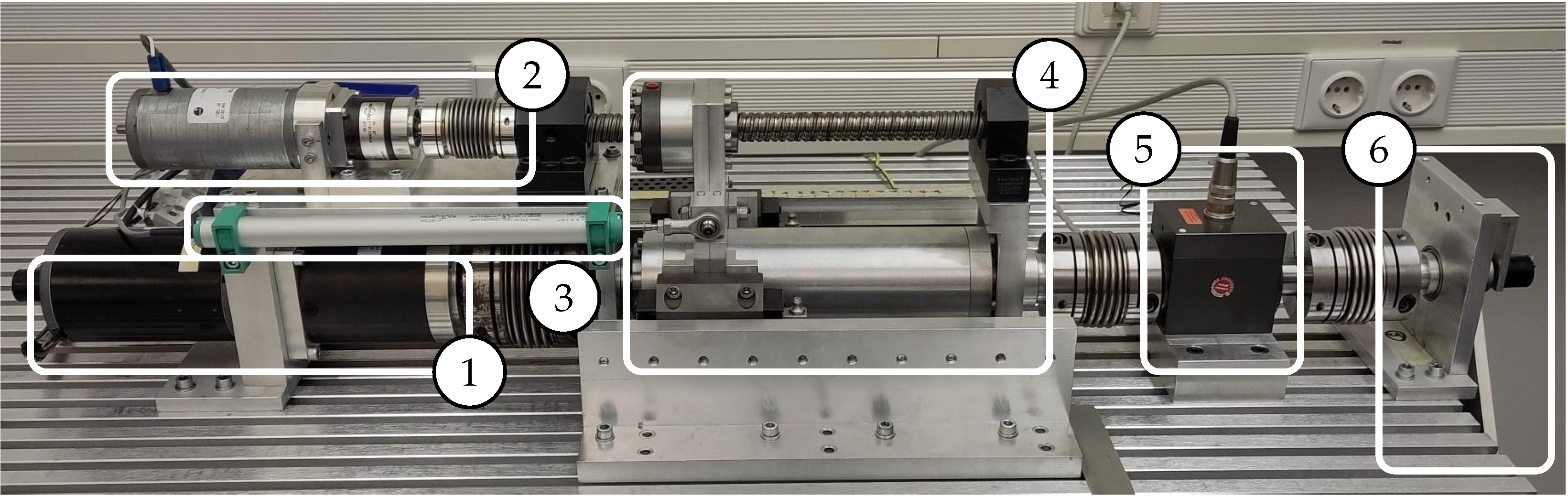
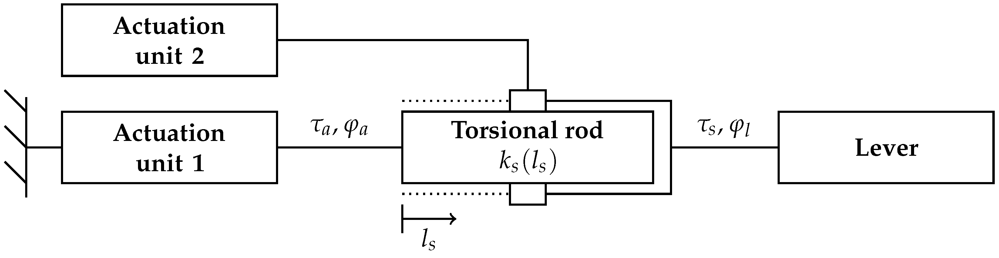
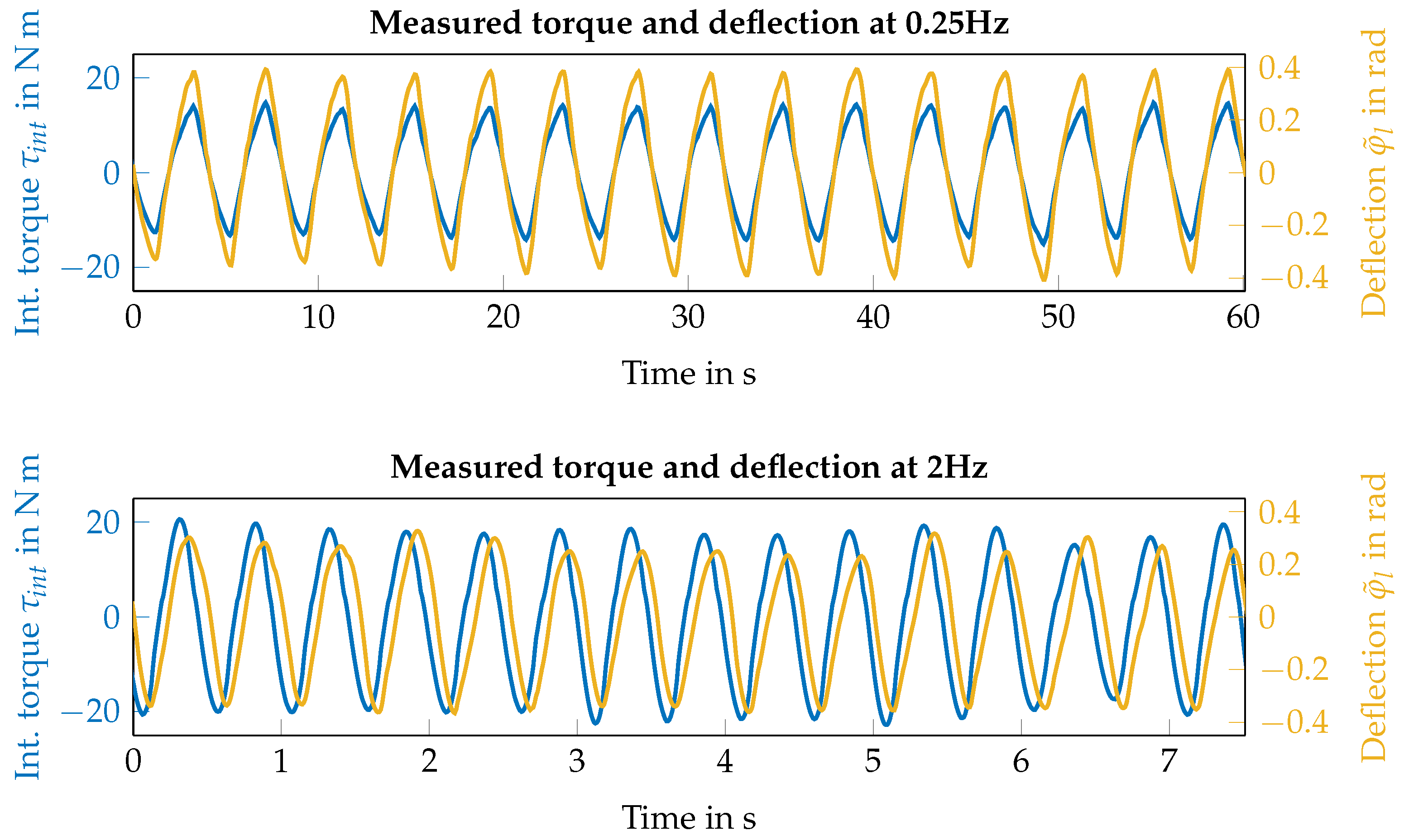
2.1. Variable Torsional Stiffness Actuator
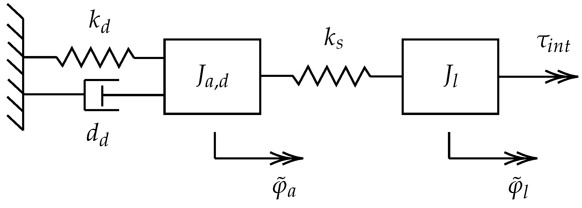
2.2. Impedance Control
- Setting A:, ,
- Setting B:, .
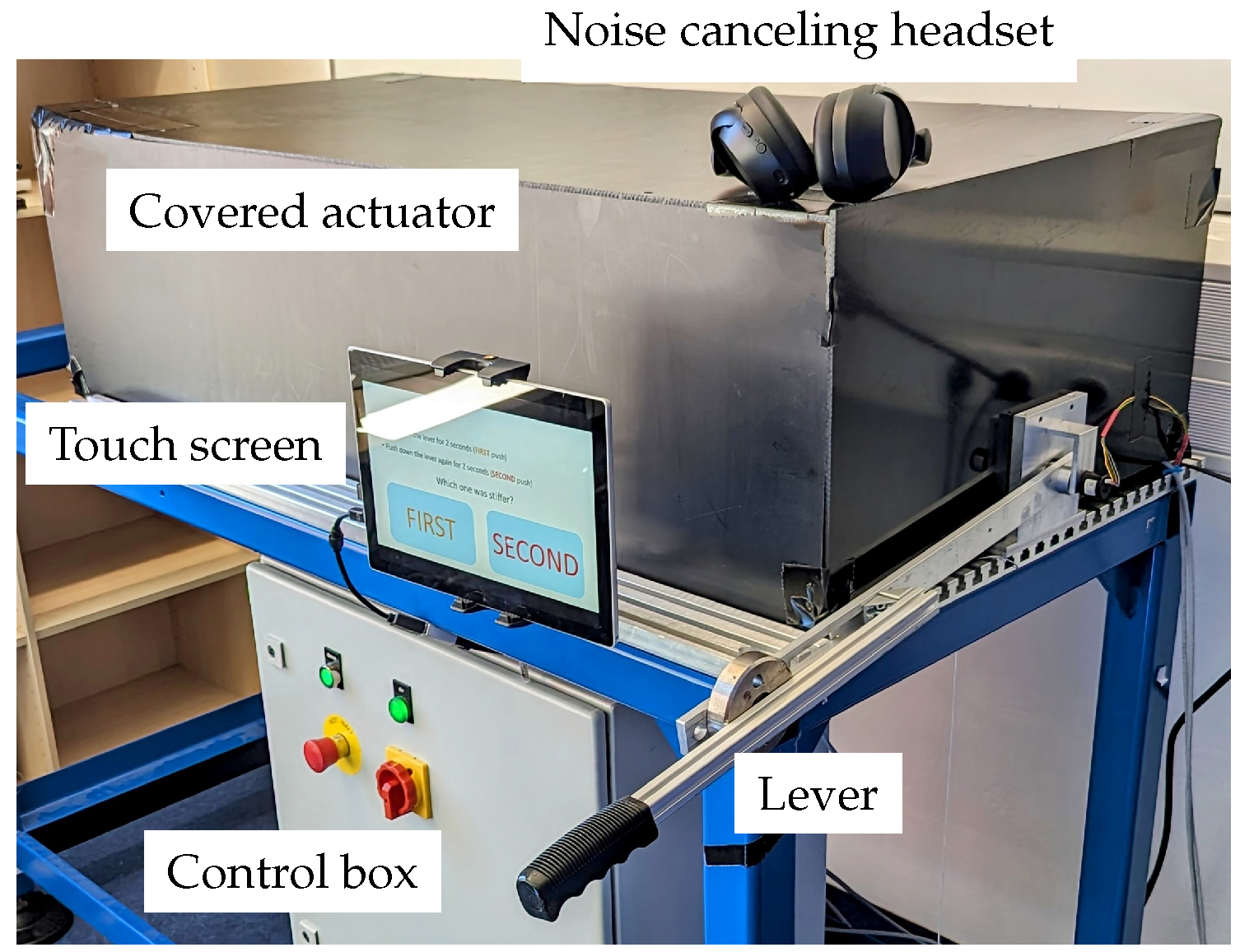
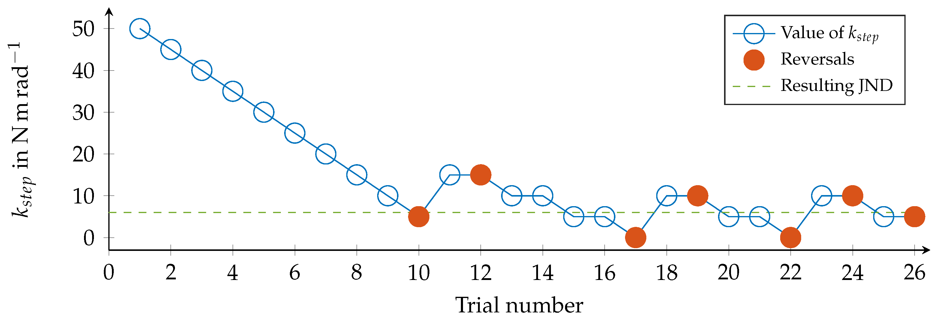
2.3. User Study
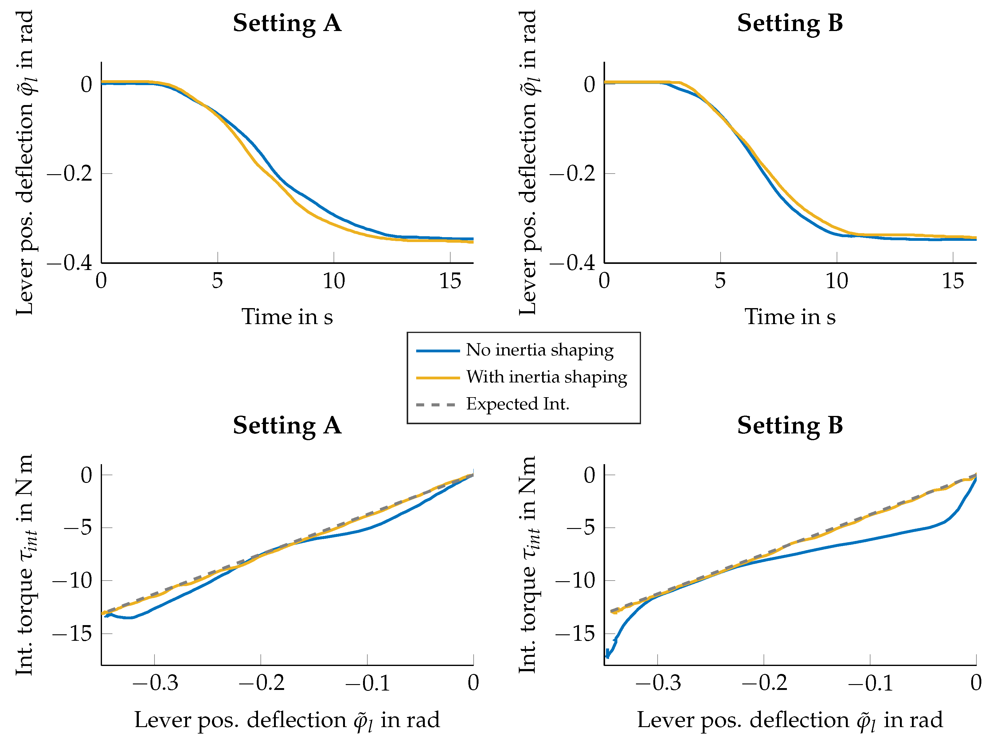
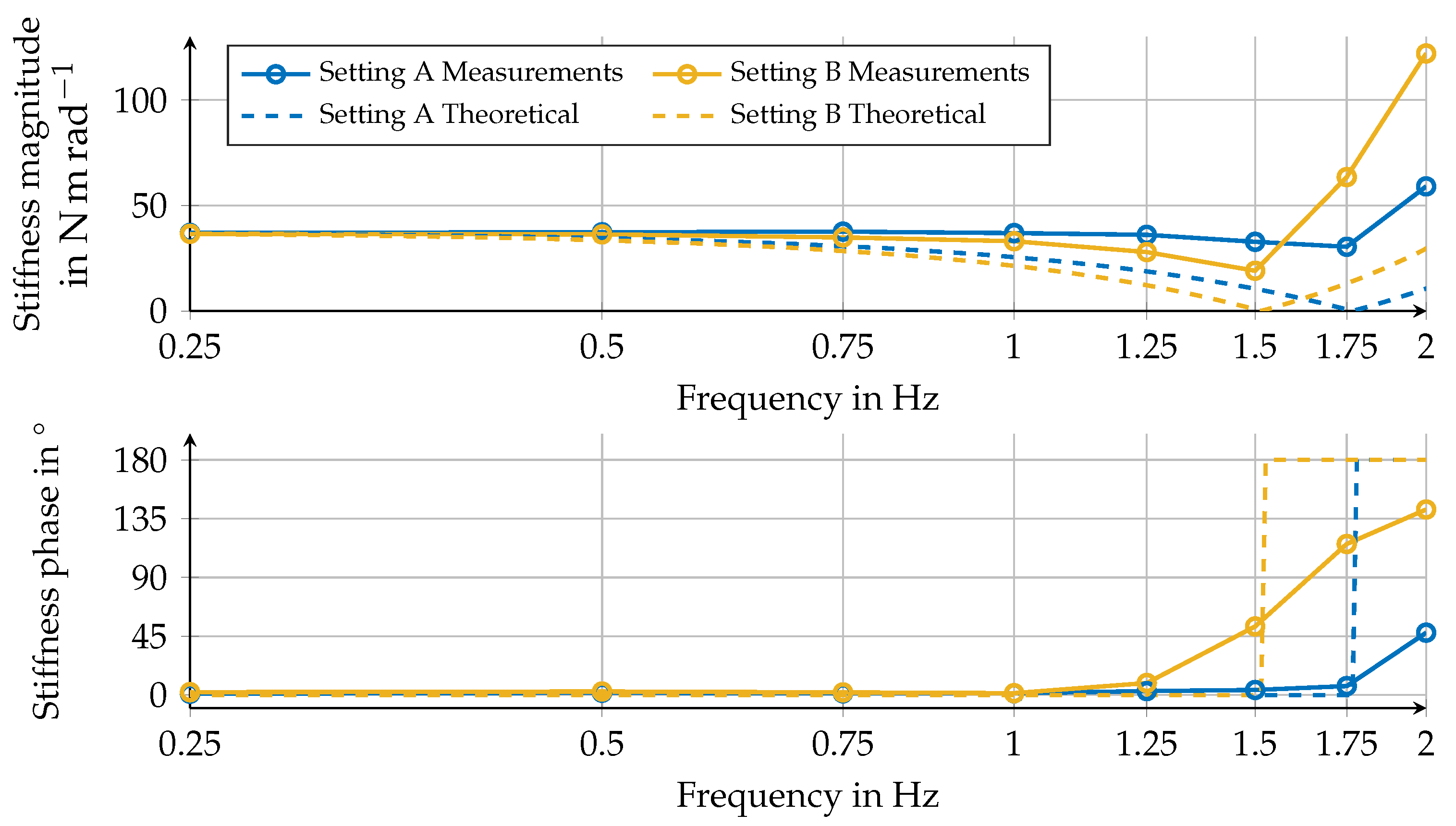
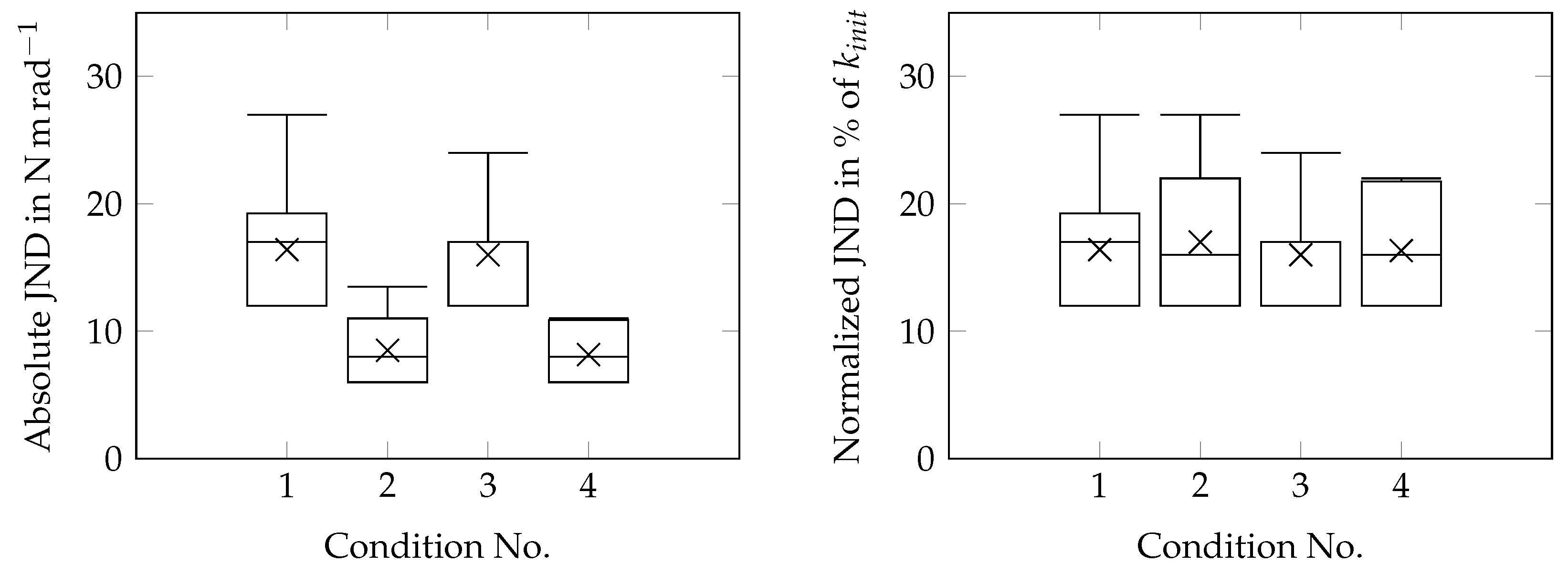
3. Results
4. Discussion
5. Conclusions
Author Contributions
Funding
Institutional Review Board Statement
Informed Consent Statement
Data Availability Statement
Conflicts of Interest
Abbreviations
| MDPI | Multidisciplinary Digital Publishing Institute |
| JND | Just Noticeable Difference |
| DC | Direct Current |
| VTS | Variable Torsional Stiffness |
| IV | Independent Variable |
| FFT | Fast Fourier Transform |
| DFG | Deutsche Forschungsgemeinschaft |
| Virtual Stiffness (of the impedance control) | |
| Real Stiffness (of the elastic element) | |
| Interaction Stiffness (Combination of virtual and real stiffness) | |
| Initial Value of Stiffness during an experiment | |
| Increase in the Value of Stiffness in between movements of a trial |
References
- Tiboni, M.; Borboni, A.; Vérité, F.; Bregoli, C.; Amici, C. Sensors and Actuation Technologies in Exoskeletons: A Review. Sensors 2022, 22, 884. [Google Scholar] [CrossRef] [PubMed]
- Sun, Y.; Tang, P.; Zheng, J.; Dong, D.; Chen, X.; Bai, L.; Ge, W. Optimal Design of a Nonlinear Series Elastic Actuator for the Prosthetic Knee Joint Based on the Conjugate Cylindrical Cam. IEEE Access 2019, 7, 140846–140859. [Google Scholar] [CrossRef]
- Beckerle, P.; Verstraten, T.; Mathijssen, G.; Furnemont, R.; Vanderborght, B.; Lefeber, D. Series and Parallel Elastic Actuation: Influence of Operating Positions on Design and Control. IEEE/ASME Trans. Mechatronics 2017, 22, 521–529. [Google Scholar] [CrossRef]
- Sensinger, J.; Weir, R.F. Improvements to Series Elastic Actuators. In Proceedings of the 2006 2nd IEEE/ASME International Conference on Mechatronics and Embedded Systems and Applications, Beijing, China, 13–16 August 2006. [Google Scholar] [CrossRef]
- Rouse, E.J.; Mooney, L.M.; Herr, H.M. Clutchable series-elastic actuator: Implications for prosthetic knee design. Int. J. Robot. Res. 2014, 33, 1611–1625. [Google Scholar] [CrossRef]
- Beckerle, P.; Stuhlenmiller, F.; Rinderknecht, S. Stiffness Control of Variable Serial Elastic Actuators: Energy Efficiency through Exploitation of Natural Dynamics. Actuators 2017, 6, 28. [Google Scholar] [CrossRef]
- Vanderborght, B.; Albu-Schaeffer, A.; Bicchi, A.; Burdet, E.; Caldwell, D.; Carloni, R.; Catalano, M.; Eiberger, O.; Friedl, W.; Ganesh, G.; et al. Variable impedance actuators: A review. Robot. Auton. Syst. 2013, 61, 1601–1614. [Google Scholar] [CrossRef]
- Penzlin, B.; Bergmann, L.; Li, Y.; Ji, L.; Leonhardt, S.; Ngo, C. Design and First Operation of an Active Lower Limb Exoskeleton with Parallel Elastic Actuation. Actuators 2021, 10, 75. [Google Scholar] [CrossRef]
- Aguirre-Ollinger, G.; Yu, H. Lower-Limb Exoskeleton with Variable-Structure Series Elastic Actuators: Phase-Synchronized Force Control for Gait Asymmetry Correction. IEEE Trans. Robot. 2021, 37, 763–779. [Google Scholar] [CrossRef]
- Vantilt, J.; Tanghe, K.; Afschrift, M.; Bruijnes, A.K.; Junius, K.; Geeroms, J.; Aertbeliën, E.; Groote, F.D.; Lefeber, D.; Jonkers, I.; et al. Model-based control for exoskeletons with series elastic actuators evaluated on sit-to-stand movements. J. Neuroeng. Rehabil. 2019, 16. [Google Scholar] [CrossRef] [PubMed]
- Carney, M.E.; Shu, T.; Stolyarov, R.; Duval, J.F.; Herr, H.M. Design and Preliminary Results of a Reaction Force Series Elastic Actuator for Bionic Knee and Ankle Prostheses. IEEE Trans. Med. Robot. Bionics 2021, 3, 542–553. [Google Scholar] [CrossRef]
- Beckerle, P. Practical relevance of faults, diagnosis methods, and tolerance measures in elastically actuated robots. Control. Eng. Pract. 2016, 50, 95–100. [Google Scholar] [CrossRef]
- Velasco-Guillen, R.J.; Grosu, V.; Vanderborght, B.; Font-Llagunes, J.M.; Beckerle, P. Experimental Evaluation of a Stiffness-Fault-Tolerant Control Strategy on an Elastic Actuator for Wearable Robotics. In Proceedings of the 2022 9th IEEE RAS/EMBS International Conference for Biomedical Robotics and Biomechatronics (BioRob), Seoul, Republic of Korea, 21–24 August 2022. [Google Scholar] [CrossRef]
- Grunwald, M. Human Haptic Perception Basics And Applications; Birkhauser: Boston, MA, USA, 2008. [Google Scholar]
- Gescheider, G.A. Psychophysics: Method, Theory, and Application; Psychology Press: London, UK, 1985. [Google Scholar]
- Koçak, U.; Palmerius, K.L.; Forsell, C.; Ynnerman, A.; Cooper, M. Analysis of the JND of Stiffness in Three Modes of Comparison. In Haptic and Audio Interaction Design; Springer: Berlin/Heidelberg, Germany, 2011; pp. 22–31. [Google Scholar] [CrossRef]
- Fu, W.; van Paassen, M.M.R.; Mulder, M. On the relationship between the force JND and the stiffness JND in haptic perception. In Proceedings of the ACM Symposium on Applied Perception, Cottbus, Germany, 16–17 September 2017. [Google Scholar] [CrossRef]
- Fu, W.; Landman, A.; van Paassen, M.M.; Mulder, M. Modeling Human Difference Threshold in Perceiving Mechanical Properties From Force. IEEE Trans. -Hum.-Mach. Syst. 2018, 48, 359–368. [Google Scholar] [CrossRef]
- Singhala, M.; Brown, J.D. Prefatory study of the effects of exploration dynamics on stiffness perception. In Proceedings of the 2020 IEEE Haptics Symposium (HAPTICS), Washington, DC, USA, 25 June 2020. [Google Scholar] [CrossRef]
- Norwich, K.H. On the theory of Weber fractions. Percept. Psychophys. 1987, 42, 286–298. [Google Scholar] [CrossRef] [PubMed]
- Shepherd, M.K.; Azocar, A.F.; Major, M.J.; Rouse, E.J. Amputee perception of prosthetic ankle stiffness during locomotion. J. Neuroeng. Rehabil. 2018, 15, 1–10. [Google Scholar] [CrossRef] [PubMed]
- Clites, T.R.; Shepherd, M.K.; Ingraham, K.A.; Wontorcik, L.; Rouse, E.J. Understanding patient preference in prosthetic ankle stiffness. J. Neuroeng. Rehabil. 2021, 18, 1–16. [Google Scholar] [CrossRef] [PubMed]
- Schuy, J.; Beckerle, P.; Wojtusch, J.; Rinderknecht, S.; von Stryk, O. Conception and evaluation of a novel variable torsion stiffness for biomechanical applications. In Proceedings of the 2012 4th IEEE RAS & EMBS International Conference on Biomedical Robotics and Biomechatronics (BioRob), Rome, Italy, 24–27 June 2012. [Google Scholar] [CrossRef]
- Ott, C. Cartesian Impedance Control of Redundant and Flexible-Joint Robots; Springer: Berlin/Heidelberg, Germany, 2008. [Google Scholar] [CrossRef]
- Stuhlenmiller, F.; Velasco-Guillen, R.J.; Rinderknecht, S.; Beckerle, P. Fault-Tolerant Physical Human-Robot Interaction via Stiffness Adaptation of Elastic Actuators. In Proceedings of the Human-Friendly Robotics 2019; Ferraguti, F., Villani, V., Sabattini, L., Bonfè, M., Eds.; Springer International Publishing: Cham, Switzerland, 2020; pp. 73–87. [Google Scholar] [CrossRef]
- Mostaghel, N. A non-standard analysis approach to systems involving friction. J. Sound Vib. 2005, 284, 583–595. [Google Scholar] [CrossRef]
- Kingdom, F.A.A.; Prins, N. Psychophysics A Practical Introduction, 2nd ed.; Academic Press: London, UK, 2016. [Google Scholar]
- García-Pérez, M.A. Forced-choice staircases with fixed step sizes: Asymptotic and small-sample properties. Vis. Res. 1998, 38, 1861–1881. [Google Scholar] [CrossRef]
- Ståhle, L.; Wold, S. Analysis of variance (ANOVA). Chemom. Intell. Lab. Syst. 1989, 6, 259–272. [Google Scholar] [CrossRef]


| Description | Symbol | Value | Unit |
|---|---|---|---|
| Mass of the lever | 1.3 | ||
| Distance to center of mass of the lever | 0.4 | ||
| Moment of inertia of the lever | 0.29 | ||
| Moment of inertia of Actuation Unit 1 | 2 | ||
| Viscous friction coefficient of Actuator unit 1 | 4 | ||
| Coulomb friction coefficient of Actuator unit 1 | 5.5 | ||
| Shaping factor for friction model | S | 5 | 1 |
| Rod length range | 0.0275–0.19 | ||
| Rod stiffness (real) range | 43–220 | ||
| Control stiffness (virtual) range | 43–220 | ||
| Control damping (virtual) | 0 | ||
| Control inertia (shaped) | 0.2 |
| Cond. No. | Varied Stiffness | Initial Stiffness in N m rad−1 | of the First Trial in N m rad−1 | Stiffness Increase in N m rad−1 | Stiffness Decrease in N m rad−1 |
|---|---|---|---|---|---|
| 1 | 100 | 100 | 20 | 10 | |
| 2 | 50 | 50 | 10 | 5 | |
| 3 | 100 | 100 | 20 | 10 | |
| 4 | 50 | 50 | 10 | 5 |
| Cond. No. | Varied Stiffness | Initial Stiffness in N m rad | Mean No. of trials | Absolute JND in N m rad | Normalized JND in % of |
|---|---|---|---|---|---|
| 1 | 100 | ||||
| 2 | 50 | ||||
| 3 | 100 | ||||
| 4 | 50 |
Disclaimer/Publisher’s Note: The statements, opinions and data contained in all publications are solely those of the individual author(s) and contributor(s) and not of MDPI and/or the editor(s). MDPI and/or the editor(s) disclaim responsibility for any injury to people or property resulting from any ideas, methods, instructions or products referred to in the content. |
© 2023 by the authors. Licensee MDPI, Basel, Switzerland. This article is an open access article distributed under the terms and conditions of the Creative Commons Attribution (CC BY) license (https://creativecommons.org/licenses/by/4.0/).
Share and Cite
Velasco-Guillen, R.J.; Schofer, F.; Bliek, A.; Beckerle, P. Exploring the Just Noticeable Interaction Stiffness Differences of an Impedance-Controlled Series Elastic Actuator. Actuators 2023, 12, 378. https://doi.org/10.3390/act12100378
Velasco-Guillen RJ, Schofer F, Bliek A, Beckerle P. Exploring the Just Noticeable Interaction Stiffness Differences of an Impedance-Controlled Series Elastic Actuator. Actuators. 2023; 12(10):378. https://doi.org/10.3390/act12100378
Chicago/Turabian StyleVelasco-Guillen, Rodrigo J., Felix Schofer, Adna Bliek, and Philipp Beckerle. 2023. "Exploring the Just Noticeable Interaction Stiffness Differences of an Impedance-Controlled Series Elastic Actuator" Actuators 12, no. 10: 378. https://doi.org/10.3390/act12100378