1. Introduction
According to the United Nations, the population above the age of 65 is projected to rise from 9% as of their last survey [
1] in 2019 to around 16% by the year 2050. While exoskeletons have been around for a reasonably long period of time, soft exoskeletons, otherwise known as ‘exosuits’, are a relatively recent development that may be a particularly interesting option for this group, given their success in providing assistance for individuals with gait-related problems such as those in post-stroke patients [
2,
3,
4,
5]. One of the earliest concepts mentioning the use of exosuits for lower limb gait assistance is the one described in [
6], that investigated the use of textiles for force transmission. Their exosuit provided assistance to the hip and ankle, using pressure sensors at the heel to determine the gait phase. It stored a predetermined gait curve which was sent as an input for the implemented position controller to actuate the motors. Their prototype achieved a metabolic cost reduction of 6.4%. The same authors improved their design in [
7]. The new control system added gyroscopes and a load cell to determine gait phase data. This exosuit was capable of transmitting 150 N of force at the hip which corresponds to about 19% of biological torque.
In [
8], a multi-joint external actuator was used to test iterative control using IMUs. The actuation system was mounted on a table next to the wearer, with Bowden cables transmitting the forces back to the subject. The actuator position and force were sent as feedback to control the quantity of hip extension. The authors in [
9] had a similar concept, with ankle plantar flexion actuation.
Other designs, such as the one in [
10], allowed the actuation of hip, knee, and ankle using McKibben pneumatic actuators. These exosuits worked by having an external compressor, which led to a total system weight of 9.1 kg. The weight of the exosuit itself, the transmission losses, and the lack of sensors for more refined control highlight the fact that both assistive force and overall system weight need to offset each other significantly for an assistive device to ultimately be useful in gait assistance.
A more complex design [
11] included three inertial sensors per leg and two load cells to determine different gait phases. The exosuit controlled the tension in the Bowden cables by measuring the force applied using an adaptive controller. The proposed design was able to reduce metabolic cost by 14.9%. A multi-joint external actuator used to test iterative control using IMUs in a lower limb exosuit was shown in [
8]. They had the actuation system mounted on a table next to the user in order to perform the tests, with Bowden cables transmitting the forces to the subject. The controller measured actuator position and force as feedback for controlling the hip extension. A metabolic reduction of about 8.5% was obtained. They used a similar setup in [
9], this time with ankle plantar flexion actuation included. The metabolic consumption improved by up to 14.6% with multi-joint actuation. In [
12], an exosuit based on PD control using an iterative learning controller was presented. Kinematic data were obtained from IMUs and load cells for control and gait detection, as well as to measure the cables forces. The system was able to obtain a reduction of up to 15.67% in metabolic cost. One of the most recent designs [
13] talks about an exosuit that weighs just 1.8 kg. IMUs were used to detect gait cycle, then determine the assistive force and execution time required, taking into account the forces measured and position data from the encoders. As it weighed less, the system was able to transmit less force (between 50–100 N) than other designs, but still managed to obtain a metabolic cost reduction of 11.52%. The XoSoft EU project [
14] created an exosuit for people with mobility issues. One of their versions, called prototype beta 1, used an elastic band and a series clutch. Step detection was carried out using force sensitive resistors (FSRs). This work notably improved the gait and postures by increasing the overall swing angles of the segments at different points during the gait cycle. Another design [
15] used extensometers and IMUs to measure angles and estimate the gait cycle from these measurements. FSRs were used at the heel to detect the gait phase. This design was different from the rest as it used current control for the motor to generate the required forces, as it was more impervious to external interference.
In order to further improve the weight savings in the final exosuit design, methods such as Topology Optimization can be used to reduce the total weight of the exosuit even further, as evidenced in studies such as [
16,
17]. Such weight optimizations improve wearability and user comfort, as the user has to bear lesser loads from the self-weight of the exosuit, further delaying fatigue. Moreover, this improves the resulting gait assistance provided, as the overall weight being moved is lower. Moreover, simple design details such as using wider straps to distribute the weight over a larger surface area are good philosophies and, accordingly, the backpack with the widest straps available was used in this exosuit prototype. Custom leg braces were also fabricated to better improve wearer comfort and apply the force over a wider area on the leg rather than on a specific point.
In this paper, the authors present and test a working prototype for a walking-assistance exosuit based on postural synergies, following their previous work in [
18], where they introduced a new design approach aiming for a notable reduction in the number of required actuators. The prototype has an actuation unit consisting of only one motor, capable of actuating the hip joint at both legs, although it could be extended to the knee and hip actuation. The transmission system consists of Bowden cables and pulleys designed to best replicate their movement during gait, being able to also actuate the ankle and knee joint while staying with only one actuator. The overall system uses one IMU per leg and FSRs for the detection of the gait phase, while the actuation unit weighs around 5 kg and is located in a backpack. The system is expected to provide between 15% and 30% of the total joint torque, focusing on the most demanding phases during gait, without interfering in the subject’s kinematics.
Kinematic synergies are a useful way to correlate the actuation of different segments with the number of actuators to be used. This concept could be used in two ways: first, to combine multiple actuators for gait assist, to use the concept to reduce the number of actuators needed to provide assistance to a given number of segments. Synergies can help minimize the costs and complexity in the overall design of an exosuit, as fewer actuators mean that fewer auxiliary components are required in the system, which significantly reduces the final cost of the prototype. The most important part is that the motor torque demand curves for the ankle and hip are remarkably similar, which allows them to be actuated by the same motor using a pulley train with calculated diameters for each joint.
Considering a case in which all three joints are mechanically coupled, the actuation of the joints could only occur during a small percentage of the gait cycle. Moreover, different actuation schemes may be may required for individual users, focusing more on one joint or the other, as described by the authors in [
19]. The decomposition of the kinetics into synergies was applied to the joint torques at the hip, knee, and ankle joints. Principal components determined the similarity of the kinetic torques in the three joints analyzed and the effect of the walking speed on the coordination pattern. A total of three principal components were required to describe enough information with minimal loss. The concept of applying kinematic synergies to a lower limb exosuit to reduce the number of actuators using Bowden cables transmission was tested and verified in [
20], where experiments were performed on a test bench specially designed for synergy-based actuation and control strategies.
2. Design and Implementation of the Synergy-Based Exosuit Prototype
When designing a gait-assistance exosuit, one of the most immediate problems to address are the power limitations and the selection of the actuation phases. Based on the fact that cables cannot transmit force while under compression, the actuation range is limited to flexion only. This allows the use of just one motor to control two legs by isolating the actuation using clutches, to alter between the segment currently being actuated. The extension phase is handled by the user. During this phase, the clutches deactivate and the user only has to move the leg and, consequently, the cable without experiencing any resistance from the motor or the rest of the transmission system.
2.1. Transmission System
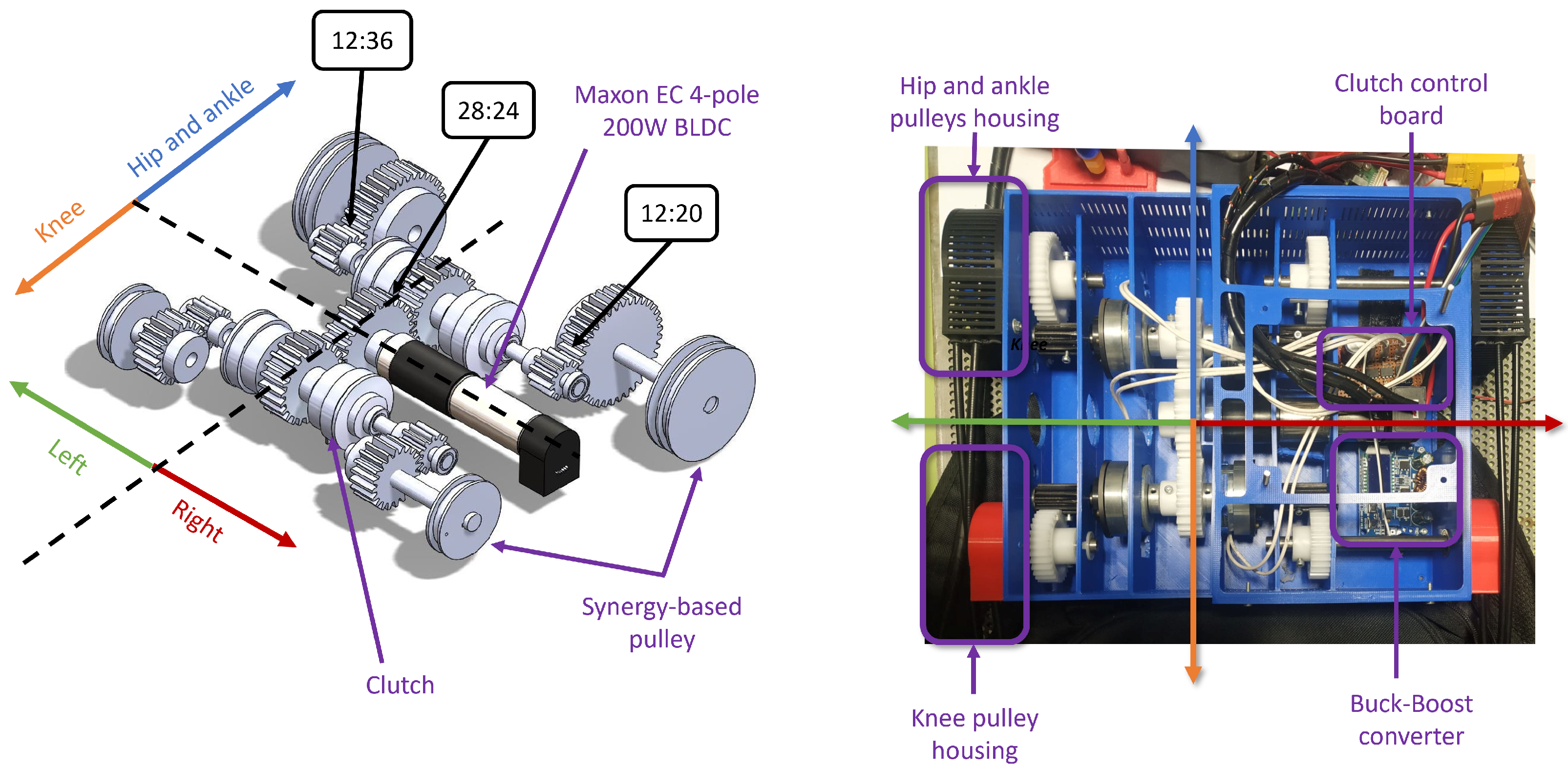
The core components of the transmission components are detailed in this section. A detailed view of this system is depicted in
Figure 1. Here, a CAD design is shown for illustrative purposes, to clarify the power transmission route. The prototype of the transmission system is also detailed.
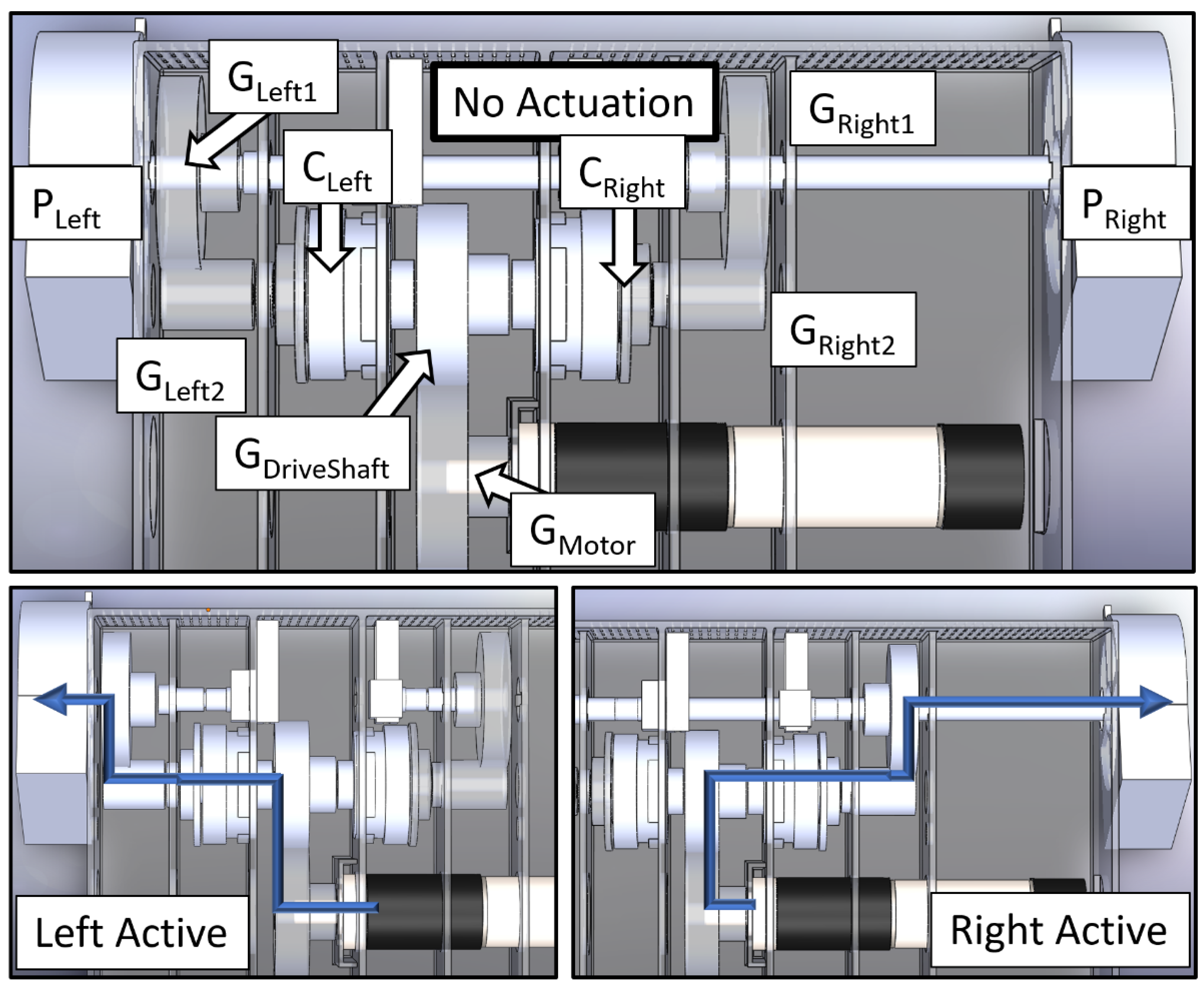
Figure 2 shows the actuation methods that are implemented using the clutches and gears in detail.
The drive system seen in the
Figure 2 consists of an overdrive stage (to prevent exceeding rated clutch torque) comprising
and
. This spins a common drive shaft, which distributes the torque to the input of two connected EM clutches:
and
. At the output from
, a reduction stage formed by
and
is used.
is connected to the output concentric pulley set
, which comprises the left side actuation unit. An identical setup is mirrored to transfer the power to the right side, comprising
,
,
, and
. Depending on the currently engaged clutch, the torque either goes entirely to the left if
is activated or the right if
is engaged instead. Logically, both clutches (
and
) can be activated simultaneously in order to actuate both legs at the same time, as it may have potential applications in cases such as providing assistance while getting up from a sitting position, etc. However, this has not been implemented in the control code, as it is not currently a design goal of this work.
When the user is standing still, none of the clutches are engaged and the cables can move freely as they are not under tension. If the left segment needs to be actuated, the left clutch activates and that part of the transmission system, including and , engages to transmit the torque developed by the motor to the left leg by spinning the pulley attached to it, which applies an assistive force on the wearer’s leg by winding up the cable. The power transmission path is indicated with the blue arrows. The same process applies to the right leg too, by engaging , with the path via and .
2.1.1. Motor with Its Gearbox and Encoder
In order to actuate the joints, some form of actuator is required. In this prototype, this comes in the form of a BLDC motor, specifically, a Maxon EC 4-Pole 24 V 200 W motor (Maxon Motor, Sachsein, Switzerland). BLDC motors in general are more efficient and powerful than similarly sized brushed DC motors. This particular motor was selected for its high power to weight ratio, since it provides more power than other similar motors in its weight and size class. In order to provide the torque required for the application, a suitable reduction gearbox is required. A 33:1 gearbox was chosen to provide a balance between speed and torque, to facilitate the transmission design process. This gave a resulting torque output of 3.13 Nm at the output of the gearbox, which was further increased after the transmission system involving the clutches. In order to provide feedback for the motor speed controller, the PWB AEM30 was implemented, which is an Absolute Multiturn Encoder. It has 12 single-turn bits and 20 multi-turn bits, which can be configured as needed in the communication data frame.
2.1.2. Clutches
In order to isolate the segments of the legs, the motor rotation needs to be isolated, so as to provide sufficient torque and mechanical decoupling between the left and right legs. These clutches need to be controlled by the control system, so as to provide the correct assistance to the leg, as deemed necessary by the controller. To accomplish this, electromechanical clutches were used so that they could be interfaced with the controller. The specific models used were Inertia Dynamics 2.8 Nm, 24 V clutches. These clutches were connected to a clutch control board consisting of Panasonic AQV252 Solid State Relays. The inverse dynamics model introduced in [
21], along with the study conducted in a target population (older adults of both genders) with gait data from a public dataset [
22] and anthropometric parameters from [
23], allowed the authors to estimate the maximum hip, knee, and ankle torques during gait and, thus, the shaft torques expected at the actuation unit, including the clutches, during the operation of the exosuit.
2.1.3. Gears
Since the clutches were rated for a slightly lower torque than the motor output, the torque output of the motor with respect to the motor output after the gearbox needed to be reduced in order to prevent potential damage and to prolong the lifespan. The motor torque output can be calculated as follows:
where
is the torque constant of the given motor,
is the motor current,
is the efficiency of the motor, and
and
are the absolute reduction ratios of the gearbox attached to the motor.
Two stages were implemented. The first stage was an overdrive that reduced the torque from the gearbox while simultaneously splitting it towards the two clutches by using a gear ratio of 28:24. The second stage was a reduction, which increased the torque in order to actuate the corresponding segment of the leg. In the case of the hip and ankle subsystems, a gear ratio of 12:36 was used. Regarding the knee subsystem, a gear ratio of 12:20 was required. The system distribution is shown in
Figure 1.
2.1.4. Synergy-Based Concentric Pulley Sets
In order to distribute the correct torque to the segments, specifically designed concentric pulley sets were fabricated. The pulleys were fabricated by 3D printing using high resistance PLA 870 and subsequently post-processed by annealing the printed parts for up to two hours at crystallization temperature. Pulley dimensions were calculated based on the concept of kinematic synergies from a mathematical model described in [
18]. Each pulley set was designed to actuate the hip and ankle together, as they are dimensioned differently. The knee was actuated using a separate pulley and clutch system (see
Figure 1 for further details).
2.1.5. Cables
The cables used were 1.5 mm Bowden cables with their corresponding sheaths, which were strong enough to support and transmit the efforts in the exosuit, as they were tested to withstand at least 20 kg of weight. These cables are similar to those used in, e.g., bicycle brake systems. The Bowden cables were attached to the pulley and wound around the pulley by the motor and subsequently unwound by the user when the clutches were disengaged during the extension phase.
2.2. Electronics and Control Systems
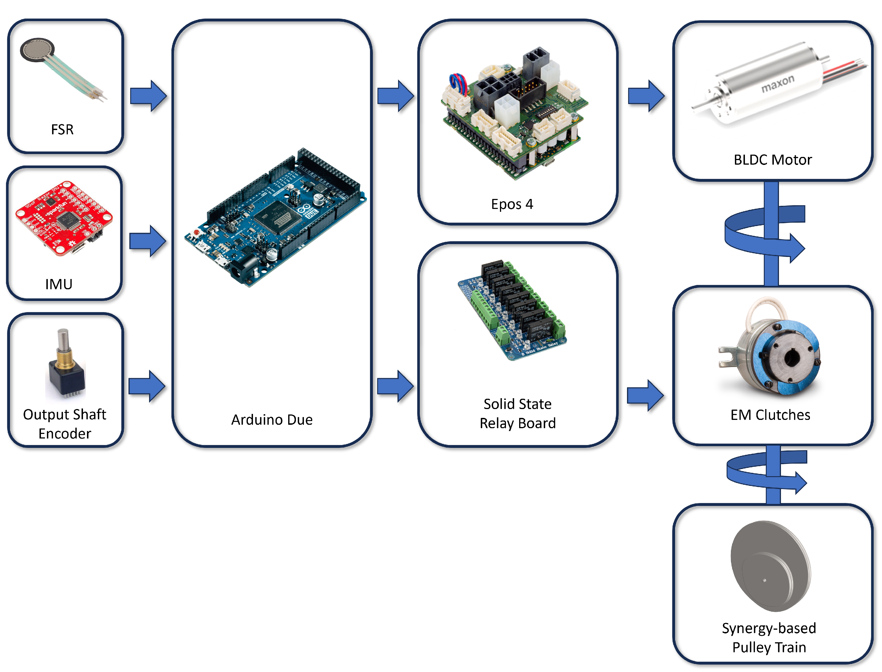
This subsection provides insight into the electronics of the exosuit. The core components to control the system of the transmission components are described in this section. A detailed scheme of the elements involved in this system is shown in
Figure 3, where the relationships between elements are presented. Briefly, different sensors such as FSRs, IMUs, and encoders provide feedback. These signals are handled by the Arduino Due, that sends control commands to the EPOS4 controller to dictate the movement of the BLDC Motor. The solid state relay board also uses those signals to engage or disengage the electromagnetic clutches, which allows the movement of the axis that provides the final actuation to the human body through synergy-based pulleys. Specific details on the design of this control board, as well as the power supply unit, that were used can be found in [
20].
While new techniques such as neural networks, etc., as seen in diverse applications such as [
24,
25], were considered, as they could potentially offer some benefits in terms of control, such methods need several high quality data points which are labeled correctly and lots of training data to reach an acceptable level of accuracy and start producing results. Moreover, exosuits are inherently vastly more complex than the applications described in those articles; thus, implementing such types of control algorithms would require significant training with multiple clearly labeled datasets, testing, and, consequently, time. Taking all this into account, such methods were not implemented for this prototype at this point in time. The aforementioned could, however, be implemented in a future version, especially when trying to design a control algorithm that can better account for significant variances in gait between users, especially for subjects with gait abnormalities or such pathologies, where the benefits of such algorithms could be better exploited.
2.2.1. Control Board
The board used to interface all the sensors and electromechanical components was an Arduino DUE featuring a 32-bit processor. This communicated with the IMUs via UART. The EPOS4 was interfaced using RS232. The FSRs were connected to the input pins. The shaft encoders were connected to pins that were defined with interrupts to detect rotation.
2.2.2. Motor Controller
For motor control, the Maxon EPOS4 50/8 was used. It received control commands from the Arduino via RS232. Communication was established using the Maxon Communication Guide to address the EPOS4 directly and minimize time delays. The motor, the encoder, and the hall sensors were connected to this module, and the encoder data were transmitted to the Arduino as needed.
2.2.3. Inertial Measurement Units (IMUs)
In order to determine the gait of the user, the gait phase estimation algorithm requires data from the segments of the legs. Some of the sensors used for this purpose were the IMUs, with 9 degrees of freedom (DoF). They determined the relative angles of the thigh and lower leg and, therefore, determined the gait phase at that moment. In this case, either Sparkfun Razor 9DoF M0 or Bosch BNO055 IMUs were used. IMUs are common elements in exosuit control and are used in several designs, such as [
8,
26].
2.2.4. Output Shaft Encoders
Since the steel cables act as torsion springs when wound around the pulley, they spin the pulley each time the clutch is disengaged, in order to relieve the tension in the pulley. This means that it is important to know the pulley position in order for successive actuation events when the clutches are reengaged. This was accomplished by using rotary encoders at the output shafts. These also provided a safeguard against the motor pulling excess cable, potentially harming the user and/or damaging the system. This was facilitated by using encoders at the output shaft of each pulley set. Taking into account the rotation speed estimated at the output and the resolution required, the encoders used were Bourns 512 Pulse Step-Direction Encoders. The authors’ recommended type of encoder for this design was an Absolute Multiturn Encoder, but these were not readily available in stock at the time of designing the system. Absolute MT encoders prevent the need to perform a full calibration when the exosuit is first switched on.
By knowing the single-turn resolution in pulses (
) of the encoder, the angular position of the pulley and cable displacement can be estimated to check whether the cable extension is too high:
where
is the number of pulses currently measured by the encoder and
is the radius of the pulley attached to its shaft.
The angular position of the output pulley can be determined by means of
where
is the current angular position of the pulley given in radians, and
and
are the absolute reduction ratios of any gearing stages that may be used.
2.2.5. Control System Elements
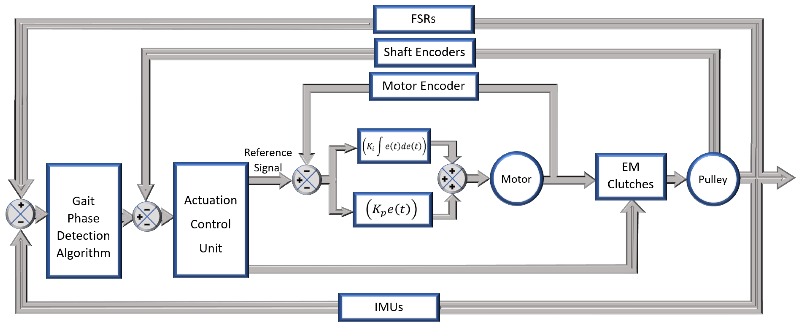
The control system plays a critical role in any such actuation device, as it makes the difference between providing an assistive force which helps the user walk and reduces metabolic consumption, and actuating at the wrong time and impeding the user movement, causing an increase in muscle activity and, consequently, potentially increased metabolic consumption. It ran on a 32-bit Arduino Due, EPOS4 motor controller, two IMUs (one per leg), two shaft encoders, and, finally, the two Force Sensitive Resistors or FSRs. The overall control diagram is shown in
Figure 4. The Arduino received inputs from all the attached sensors and fed them first into the gait-phase detection algorithm, which read the values from the IMUs and FSRs to determine the gait phase. The phases were determined by accelerations reported by the IMU, as well as FSR data, which helped determine whether the wearer was currently in flexion, extension, or standing still, among others. The gait-phase detector then sent its output, telling which leg needed assistance and what the current gait phase was to the Actuation Control Unit, which was responsible for determining the actuation levels. It took feedback from the shaft encoders, as well as the motor encoder. It then commanded the EPOS4 to start the motor at a certain torque level and velocity, using a PI current controller and velocity control. This algorithm was responsible for correctly actuating the leg requested by the gait-phase detection algorithm, which it performed by activating the corresponding clutch by sending signals to the SSR Clutch Control Board. The algorithm read the shaft encoders and IMU on each leg to provide a safeguard and prevent too much cable being drawn, thus preventing damage to the system and, more importantly, avoiding potential harm to the wearer, (i.e., providing a reliable measure of safety). Alternatively, other types of AI methods similar to those used in other applications such as [
27,
28] could be used for gait-phase detection given sufficient quantities of available data. Once such application can be seen in [
29].
The shaft encoders are important since the steel cables act as torsion springs that store energy when wound up around the pulley. This means that, every time a clutch is disengaged, the cable rotates the pulley by a random amount as it unwinds to dissipate the stored energy. Moreover, a person never covers exactly the same distance in each phase of the gait, which causes more or less cable to be left loose. The shaft encoder measures this, helps record the magnitude of rotation produced (if any), and acts to prevent too much cable from being wound up by the pulley.
2.3. Exosuit Prototype and Operation Workflow
The exosuit prototype is shown in
Figure 5 (left). In this preliminary version, customized thigh pads and ankle braces were used to place the anchor points at different positions to test different configurations. In the future, it will be necessary to replace these elements with user-centered design garments, using concepts such as lines of nonextension (LoNEs) [
30,
31], to improve comfort.
Regarding the overall working principle, as soon as the exosuit is switched on, the wearer is made to stand still, while a few samples are taken from the IMUs to establish a baseline reading to characterize the particular user’s stance and also to account for any variances in IMU position relative to the leg, etc., in order to minimize its effect on the control algorithm. Once this is completed, the gait-phase detection algorithm reads the IMUs to estimate when the leg moves forward to take a step, regardless of whether the user is left- or right-dominant, and moves the left or right leg first. As soon as the leg is determined to be in the forward position, the gait phase algorithm communicates this to the actuation control unit, which takes over. This makes the clutches engage, and the motor outputs a very low torque value, just to ensure the cable is pretensioned correctly without hampering the user’s movement, in anticipation of the heel strike. As soon as the heel strike is detected by the FSR, the motor provides a much higher torque in order to assist the user in the flexion stage. Once the IMUs detect that the leg has been flexed to the correct amount, the clutches disengage and allow the user to move the leg freely during the extension phase while the other leg is forward, and those clutches activate instead, in order to actuate the other leg. This cycle repeats as the gait-phase detection algorithm detects the movement of each leg, and the actuation control unit determines the cable extension within expected limits.
3. Assessment of the Synergy-Based Exosuit
3.1. Experimental Procedure
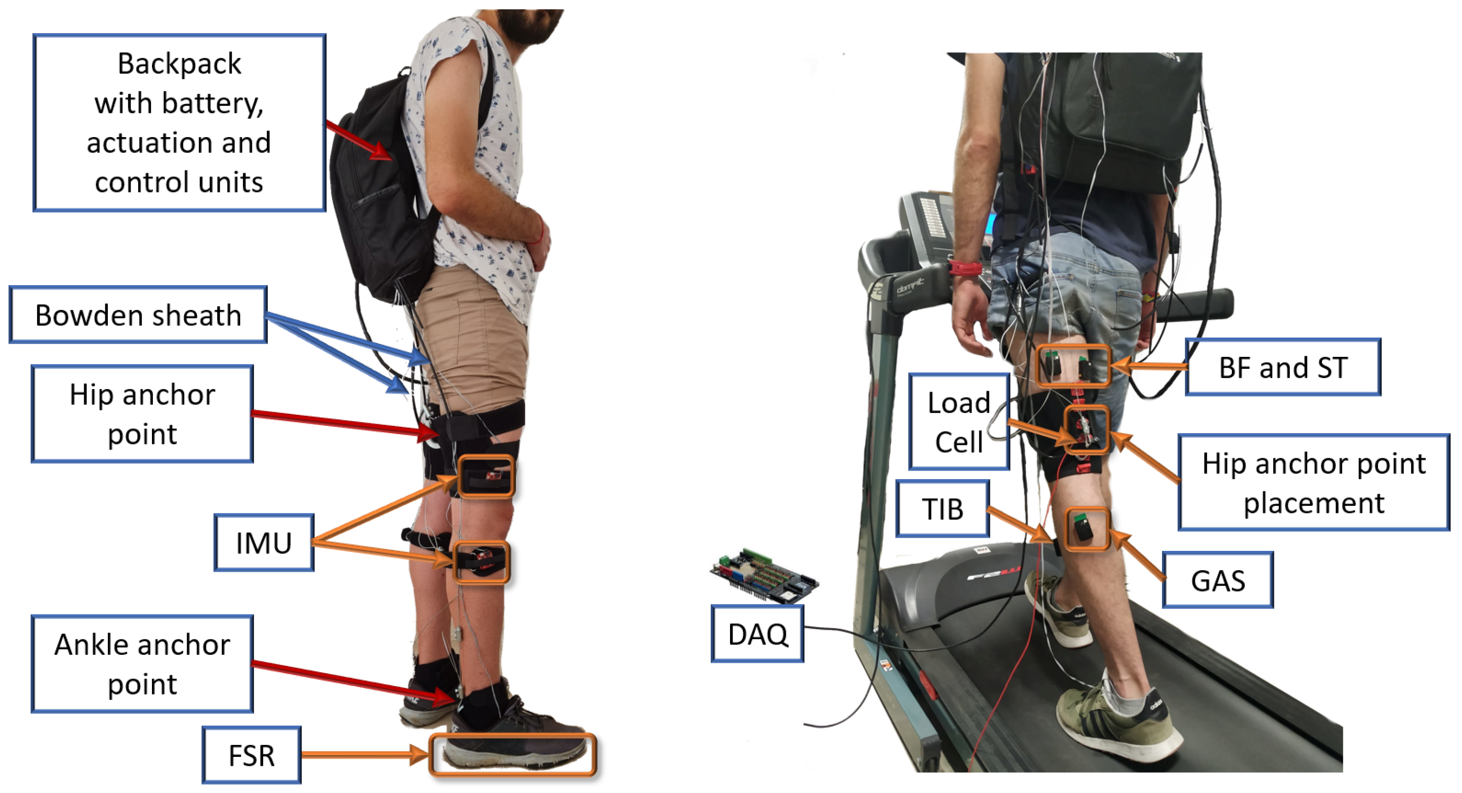
In the present work, a healthy volunteer (age: 30 years, weight: 72 kg, height: 1.83 m), who provided informed consent, was asked to walk over a treadmill (BH F2W Dual) under controlled conditions. The experimental procedure was approved by the Local Ethics Committee at University of Extremadura.
In order to test the efficacy of the exosuit, the following test was conducted: the subject was made to walk on a treadmill at a specified velocity (specifically, 3 km/h for the purposes of this experiment) while wearing sensors measuring EMG signals on the major muscle groups of interest on the leg, and a load cell between the Bowden cable which passed from the exosuit to the leg. This helped determine two different values: the EMG readings show muscle activation at the specific muscle group, and the load cell measures the actual assistive forces being transmitted to the leg by the exosuit (see
Figure 6). After 5 min of warm-up, the exosuit was placed on the test subject, tightly setting up the anchor points. The subject was asked to walk for 2 min with the exosuit powered off to become accustomed to its operation. Then, different tests were recorded; each of them consisted of walking on a treadmill for 30 s at a constant velocity of 3 km/h. Two conditions were tested: first, a test with the exosuit powered off, and second, with the exosuit powered on. If the exosuit worked, this would be shown clearly by the two sensors in the ways described in the following subsections.
3.2. EMG Readings
The EMG signals measure muscle activations in different muscle groups on the leg. When the user is walking normally, a certain reading will be measured as the baseline. On activating the exosuit, if the readings are significantly lower, this directly proves that the muscles activate less and that the exosuit is taking off some of the load, providing a useful assistive force. On the contrary, if the values are higher than the baseline, this means the muscles are working harder with the exosuit activated, indicating improper gait assistance, which could be due to incorrect gait-phase detection, improper actuation timing, or delays in actuation, among other factors such as muscle co-activation.
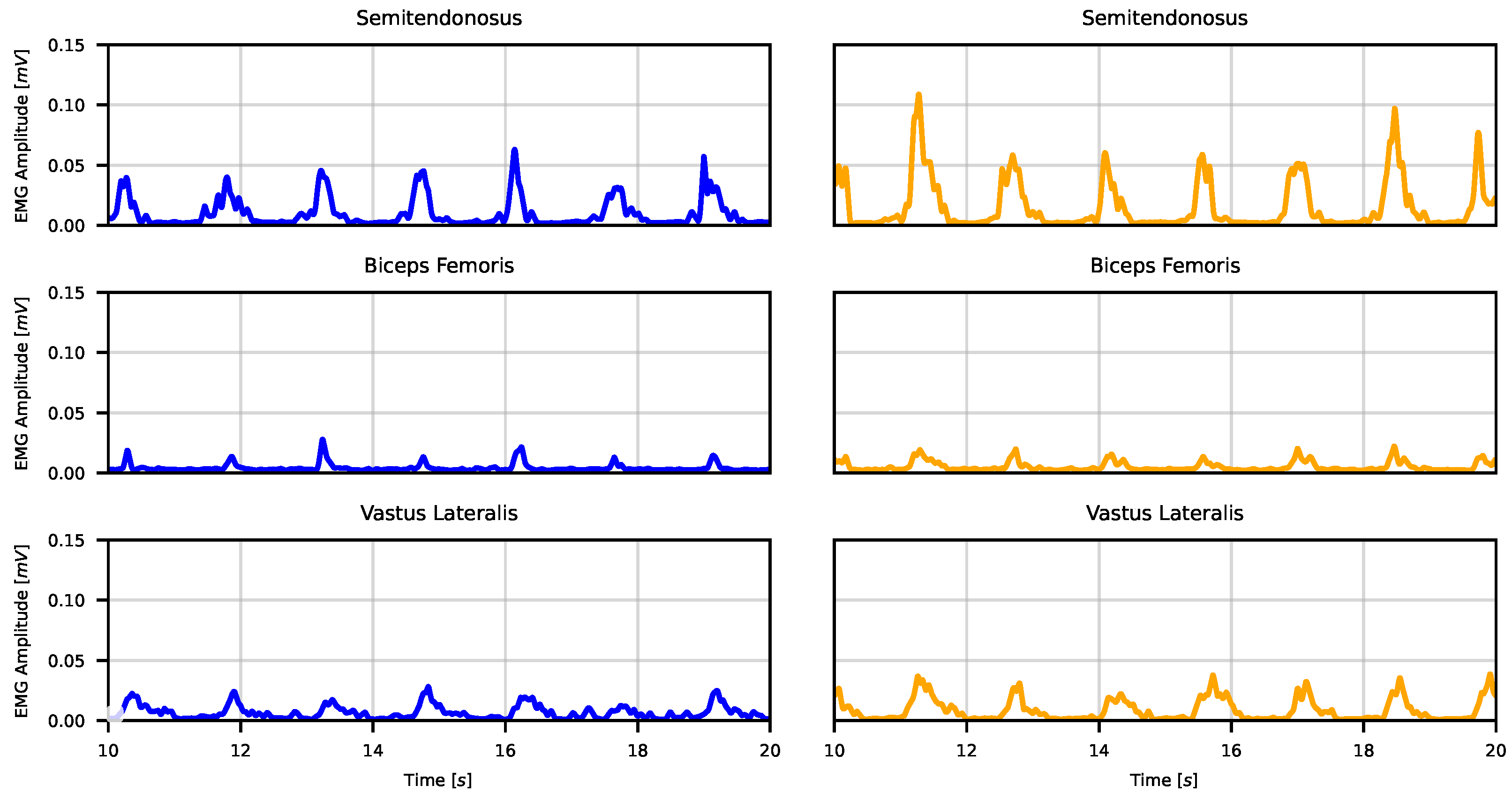
To compare both conditions, surface electromyography (sEMG) was used to measure muscle activity. Three of the main muscles involved in the movement of the hip were chosen; two of them were hip extensors (biceps femoris and semitendinosus), and the third was hip flexor (vastus lateralis). Additional sensors were placed on the tibialis anterior and the gastrocnemious muscles, but no differences were found on them between assisted and unassisted gait. The sEMG signals were recorded by means of a surface electrode Delsys
® Trigno
® system (Natick, MA, USA). at a sampling frequency of 2 kHz, according to the gold standard (SENIAM, [
32]). sEMG signals were acquired from each subject with the Delsys
® EMGworks
® (v.4.1.1) and processed in Python (v.3.10.9).
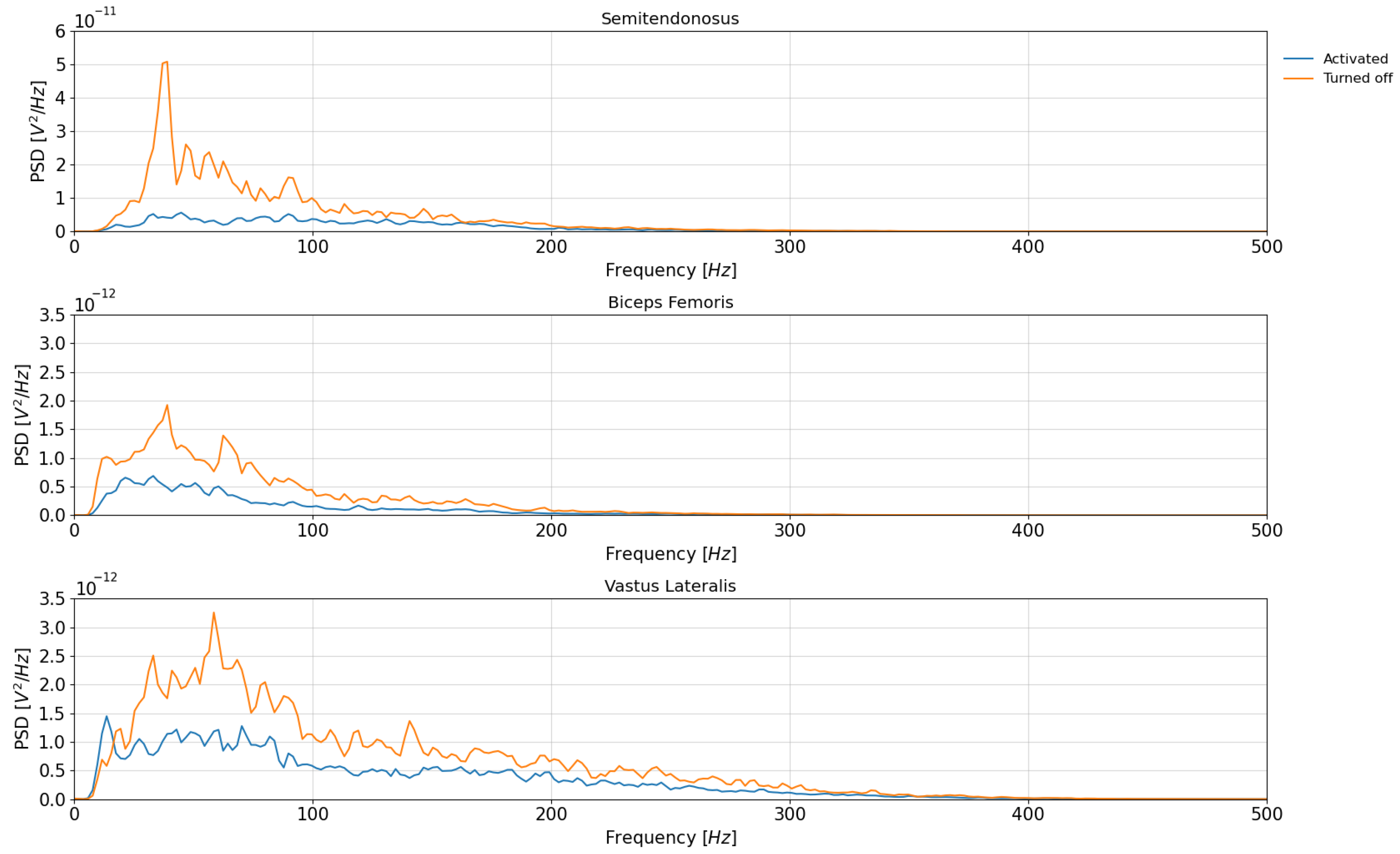
From the raw EMG data, the filtered amplitude of the muscle activity and the Power Spectral Density (PSD) were obtained. The first step to obtaining the EMG amplitude is to remove the noise from other electrical sources; for that, a Butterworth filter, with band-pass at 10–400 Hz, second order, zero lag, was used. Secondly, full-wave rectification was computed by calculating the absolute value of the signal (
Figure 7). Then, a low-pass, second-order, zero-lag Butterworth filter at 8 Hz was applied. To calculate the PSD, Welch’s method was used (
Figure 8).
3.3. Load Cell Cable Tension Readings
The load cells measure the forces being applied to the leg at any point in the gait. If the forces are measured to be high during the correct phases of the gait, this proves that the exosuit triggers correctly. Even though the human gait is somewhat cyclic, the readings fluctuate slightly, depending on the length of the step made by the user during that period of the gait. Regardless, the presence of elevated positive values of cable tension during the flexion phase is indicative of the exosuit providing an assistive force to the wearer. Additionally, low cable tension during the extension phase also indicates that the exosuit is not impeding the wearer in any significant way, which is just as important.
4. Results and Discussion
4.1. Measured Cable Tension
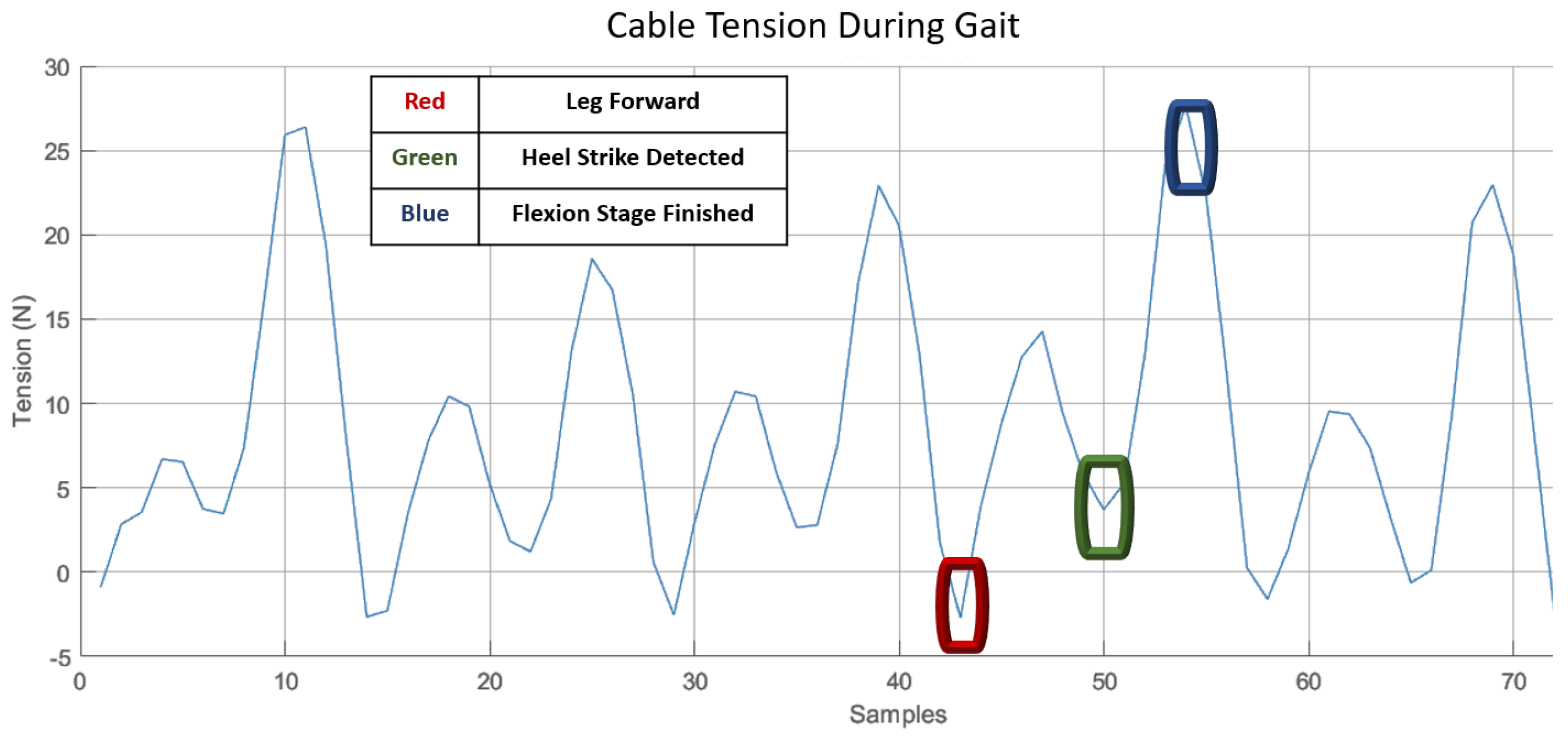
Regarding actuation, the cable tension was measured while the user was made to walk at a velocity of 3 km/h on a treadmill. During exosuit actuation, a measurable rise in cable tension occurred from the moment a heel strike was detected. In these experiments, the motor output power was intentionally limited to just 40%, for testing purposes. This value was predicted to provide enough torque for verification purposes, even if the measured peak cable tension appeared to be somewhat low.
In
Figure 6, the cable tension for the hip joint is illustrated, showing five different steps. The area to the left of the red marker represents the extension phase, while the right side shows when the leg is moved forward as sensed by the IMUs, but before the heel strike is sensed by the FSRs. Once this extension phase is finished by the user, the clutches are disengaged. The cable tension before this point was seen to be negligible or even negative, proving that the exosuit cables do not impede the user in the extension phase at all, reducing fatigue. Once the leg is detected to be in the forward position, the clutches are activated and the motor applies a very light torque which combats the slack created when the clutches disengage, helping to pretension the cable; notably, this is not detectable by the user and does not impede finishing the step. This is appreciable in
Figure 6 in the area from the red marker to the green marker.
Once the user’s foot has touched the ground and a heel strike is detected by the FSRs and IMUs, as seen in the area marked in green, the motor now applies a much higher torque, which aims to assist the user in the flexion stage, as can be seen in the spike in the graph from green to blue.
In the blue area, the algorithm detects the end of the flexion stage based on IMU readouts or shaft encoder-reported positions. When this is detected, the clutches are disengaged, allowing the user to extend the leg again without any hindrance while being supported by gravity, until the next flexion phase begins.
The cable tension readouts reported by the load cells clearly show that the cables do not impede the user from moving the leg in the extension phase. They also show that the exosuit applies a significant assistive force during the flexion phase, helping the user walk better. There were phases where the assistive force was lower than in others. This is due primarily to the fact that human gait is inherently uneven: some steps are longer than others, and this affects the overall assistive force provided.
The gait-phase algorithm and its sensors have been shown to detect gait phases with good accuracy, deciding when the user is in flexion, extension, standing, etc. It has also been able to identify potentially hazardous actuation attempts and respond correctly by limiting the actuation range to avoid damage to the exosuit and, most importantly, prevent harm to the user. Further testing with motor power set to higher values is planned to be carried out in future tests. Another improvement would be the addition of ankle and, eventually, knee assistance for even further reduced metabolic consumption. The upgrade to absolute multiturn shaft encoders would help significantly reduce the need for recalibration every time the system is turned off.
4.2. EMG Readings
Observing the EMG values shown in both
Figure 7 and
Figure 8, a clear reduction in muscle activation values is observed when the exosuit was turned on. Using the composite trapezoidal rule, the cumulative integrated value of the PSD can be obtained. A significant reduction was found when comparing the result between the exosuit-actuated gait with the gait without assistance. In the case of the muscle semitendinosus, a variation of
was calculated. A similar value of
was found in the Biceps Femoris muscle. Although the Vastus Lateralis is a pure hip flexor muscle, the results also suggest a reduction in the PSD, by
. These results may indicate that the exosuit could affect other degrees of freedom, apart from the hip extension movement.
5. Conclusions
In this manuscript, a novel approach to the design and control of exosuits has been presented. Although it was designed for subjects with gait-associated pathologies in mind, preliminary experiments were conducted on a healthy subject. The main contribution lies in the development of a synergy-based exosuit that utilizes a single motor to actuate all the lower-limb joints on both sides, resulting in a more efficient and natural gait pattern. Furthermore, it has been demonstrated that the use of pulling forces, as opposed to joint actuation, provides a more natural gait, compared to existing exoskeleton designs.
The concept of synergy-based design in exosuits involves exploiting the inherent coordination and coupling of joint movements during human locomotion. By identifying and capturing these synergistic patterns, it was possible to design an exosuit that can effectively mimic the natural movement of the lower limbs. This approach has significant advantages over traditional joint-actuated exoskeletons, which often require multiple motors and complex control algorithms to achieve desired movements.
One of the key advantages of the synergy-based exosuit is its ability to provide a more natural gait pattern. This can be attributed to several factors. First, the coordinated activation of multiple joints by a single motor enables smoother and more synchronized movements, resembling the natural muscle activation patterns while walking. Second, the use of pulling forces allows for a more intuitive and responsive control, as the forces applied to the limbs closely resemble the forces experienced during normal gait. This reduces the perceptual mismatch between the exosuit and the user, resulting in improved user comfort and acceptance.
Results of the experimental evaluation indicate that the synergy-based exosuit exhibited superior performance compared to existing exoskeleton designs. The users reported a more natural and comfortable walking experience, with reduced fatigue and improved biomechanical parameters. Moreover, the single-actuator approach significantly simplifies the control system, making it more robust and easier to implement. However, while the proposed exosuit design and control strategy have shown promising results, there are still some limitations to be addressed. Firstly, the study was conducted on a single subject, and further studies with a larger and more diverse population are necessary to generalise these findings. Additionally, long-term evaluations are required to assess the durability and reliability of the exosuit in real-world conditions. Another drawback of this study is the lack of optimization of the exosuit design in terms of weight and anchor point positions. Further studies must be performed to enhance the user’s mobility but also to reduce the physical burden associated with wearing the exosuit, making it more practical and user-friendly. The aforementioned experiments will be conducted in the near future.
In conclusion, this research presents a significant advancement to be exploited in the field of exosuit technology for individuals with gait-associated pathologies. The synergy-based design, utilizing just a single motor to actuate all lower-limb joints on both sides, offers a more natural and efficient gait pattern. The use of pulling forces and the optimization of design parameters further enhance the usability and effectiveness of the exosuit. These findings contribute to the growing body of literature in exoskeleton research and pave the way for the development of more practical and user-friendly exosuits for individuals with gait impairments. Future research should focus on addressing the remaining challenges and validating the presented approach in larger clinical trials to ensure the scalability and effectiveness of the proposed exosuit design. Despite using parts that were not optimized for weight savings due to supply issues, the entire system weighed about the same as or, in some cases, even less than other similar exosuits, such as [
10], highlighting the advantages of synergy-based design.
One of the more obvious improvements to be implemented would be the addition of the remaining segments of the leg and adapting the control system and actuation strategy to accommodate these additional segments. Since both clutches can be activated simultaneously in order to actuate both legs at the same time, the exosuit has the potential to provide assistance while getting up from a sitting position, etc. Another area for improvement would be the implementation of a more robust control algorithm capable of adapting to individual gait patterns, using any of the previously mentioned AI techniques, especially to better account for pathologies between individuals. The algorithm could be enhanced to apply a more aggressive cable tensioning algorithm—to ensure the cables are pretensioned more accurately—and to account for clutch decoupling by using better absolute multiturn encoders to minimisz the control system calibration sequence upon initialization. However, as a preliminary proof of concept, this prototype shows significant potential, with tangible results as proof.


 ,
, 


