
A Bimodal Hydrostatic Actuator for Robotic Legs with Compliant Fast Motion and High Lifting Force


Abstract
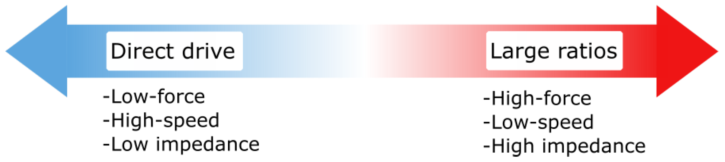
:1. Introduction
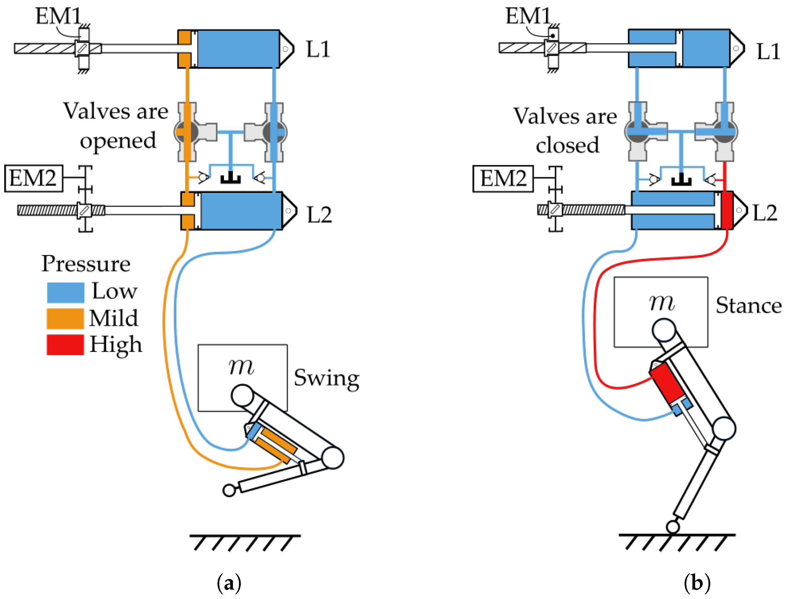
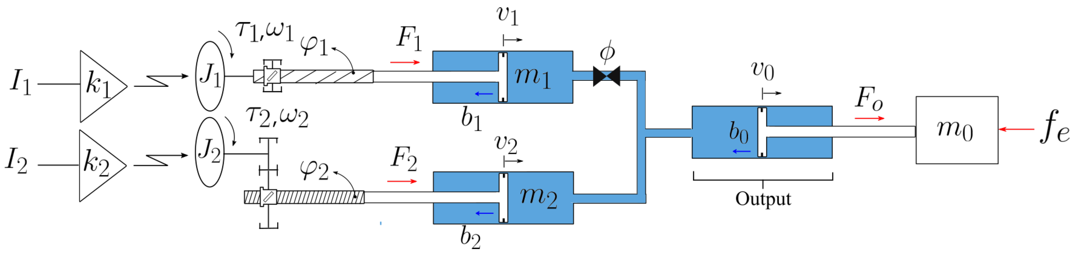
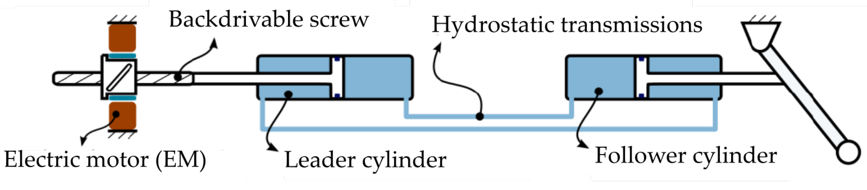
2. Working Principle
Equations of Motion
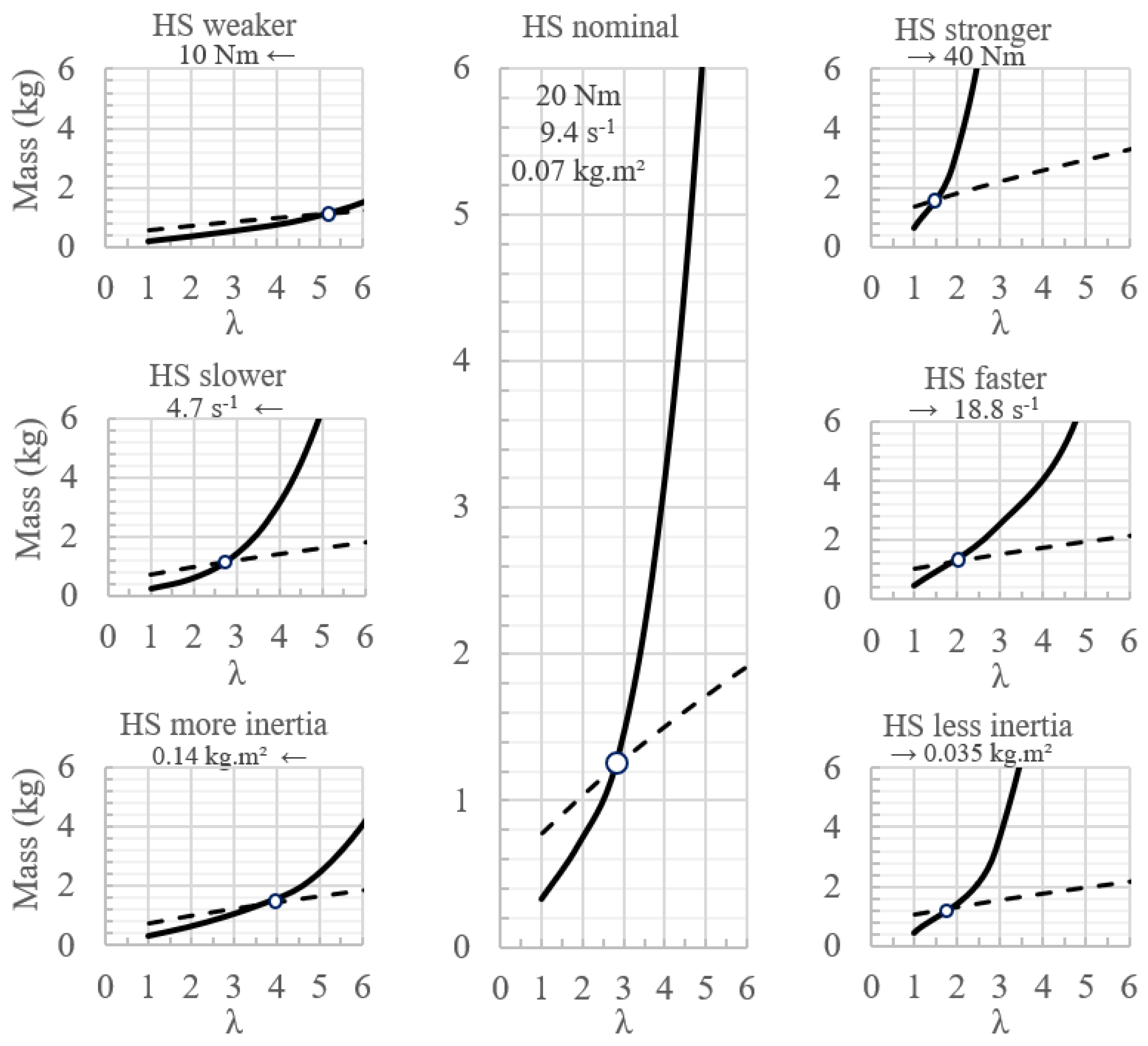
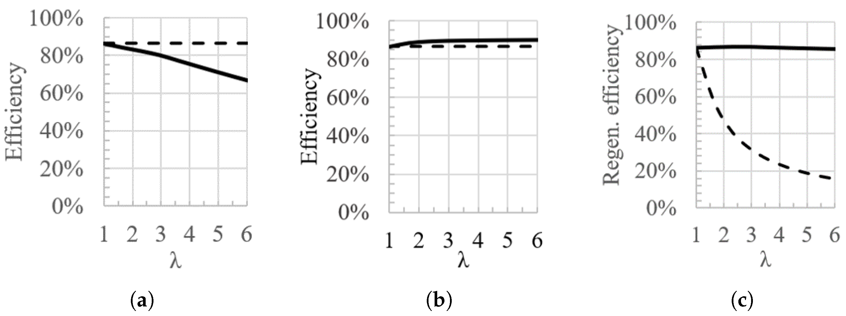
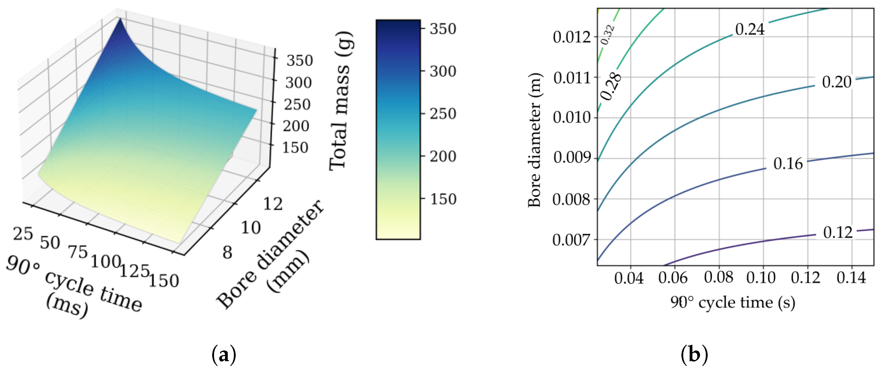
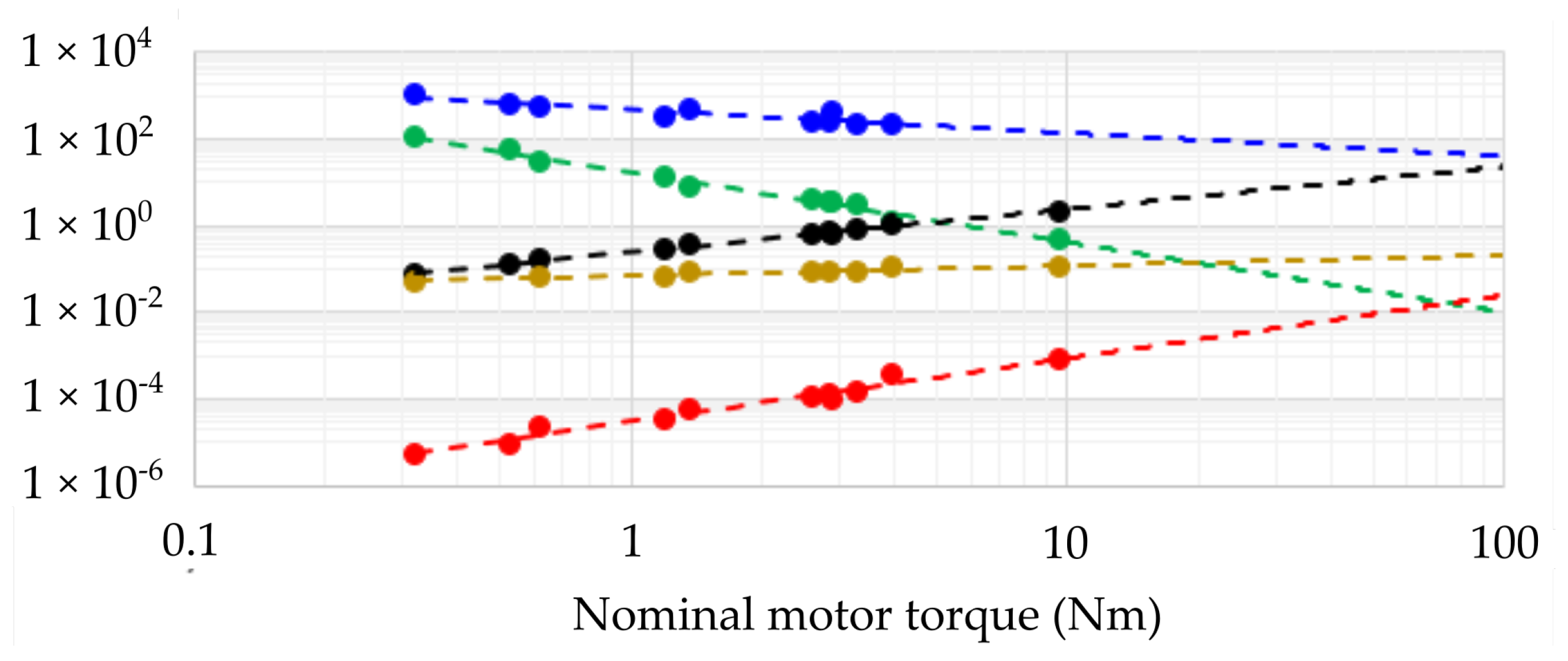
3. Mass and Efficiency Analysis
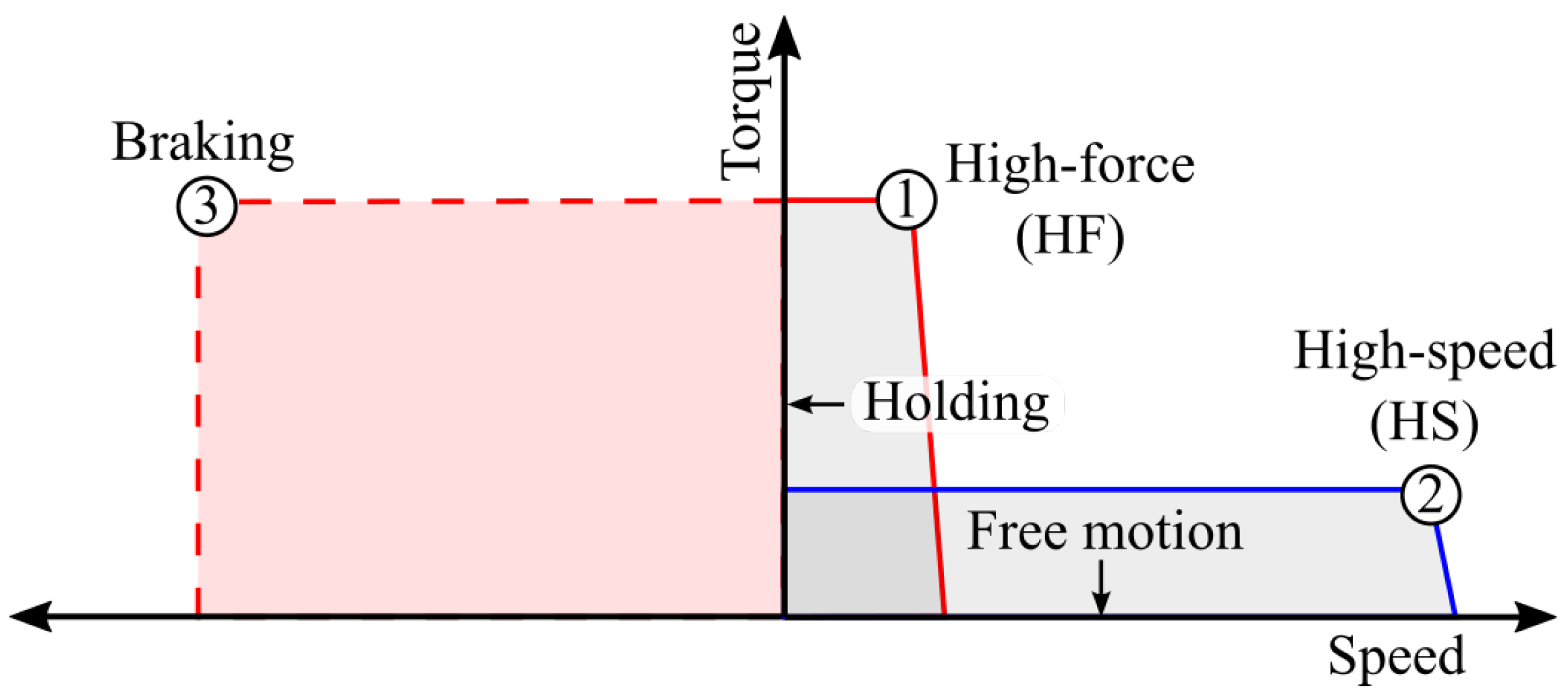
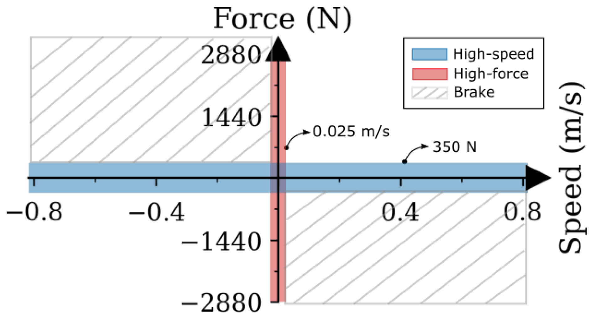
3.1. Two-Speed Design Advantage for a Robotic Knee
- High-force low-speed (HF) operating point;
- High-speed low-force (HS) operating point, with low inertia;
- High-power braking operating point, with low inertia.
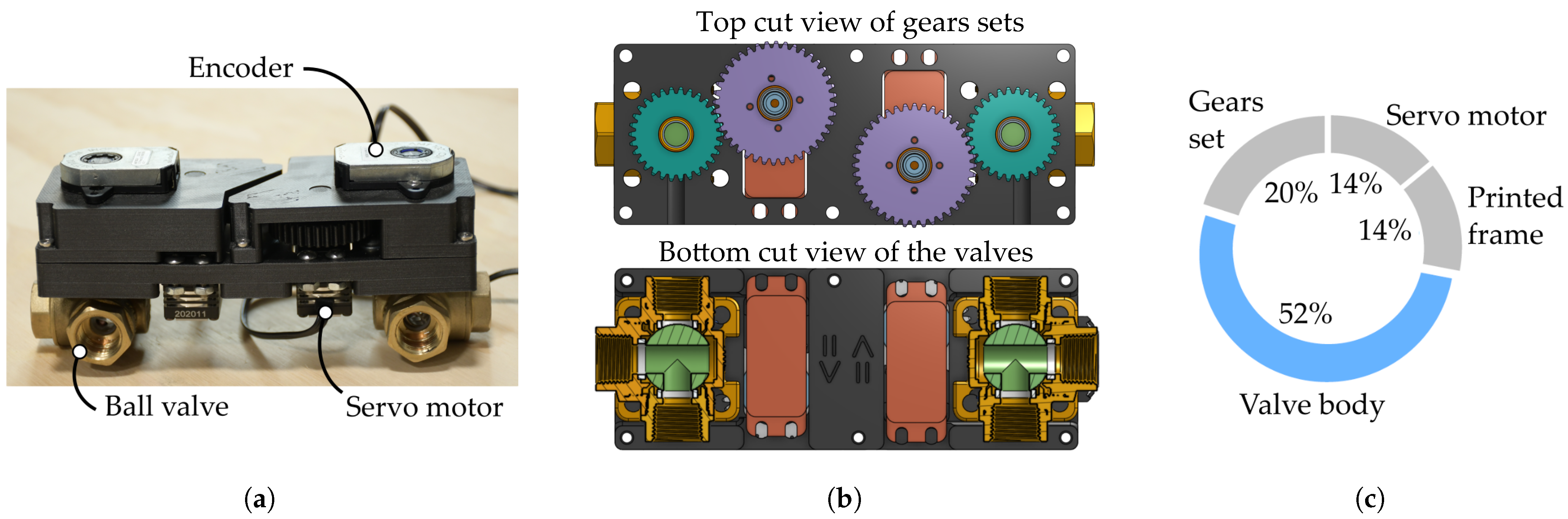
3.2. Valve Unit
4. Experimental Assessment
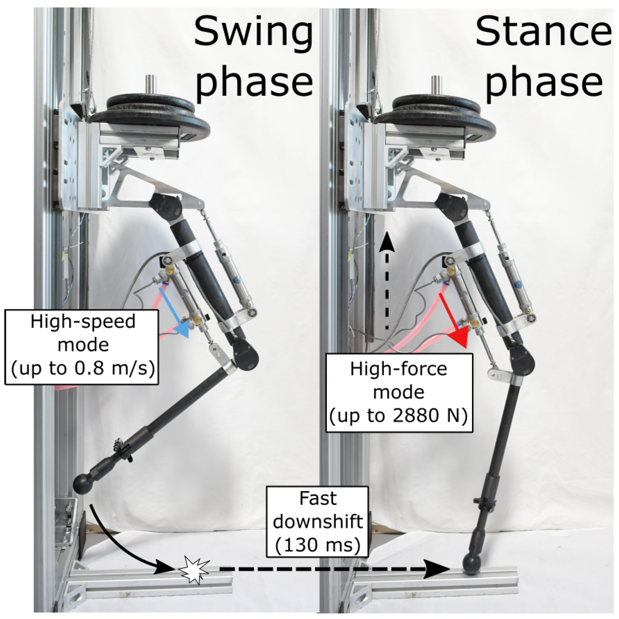
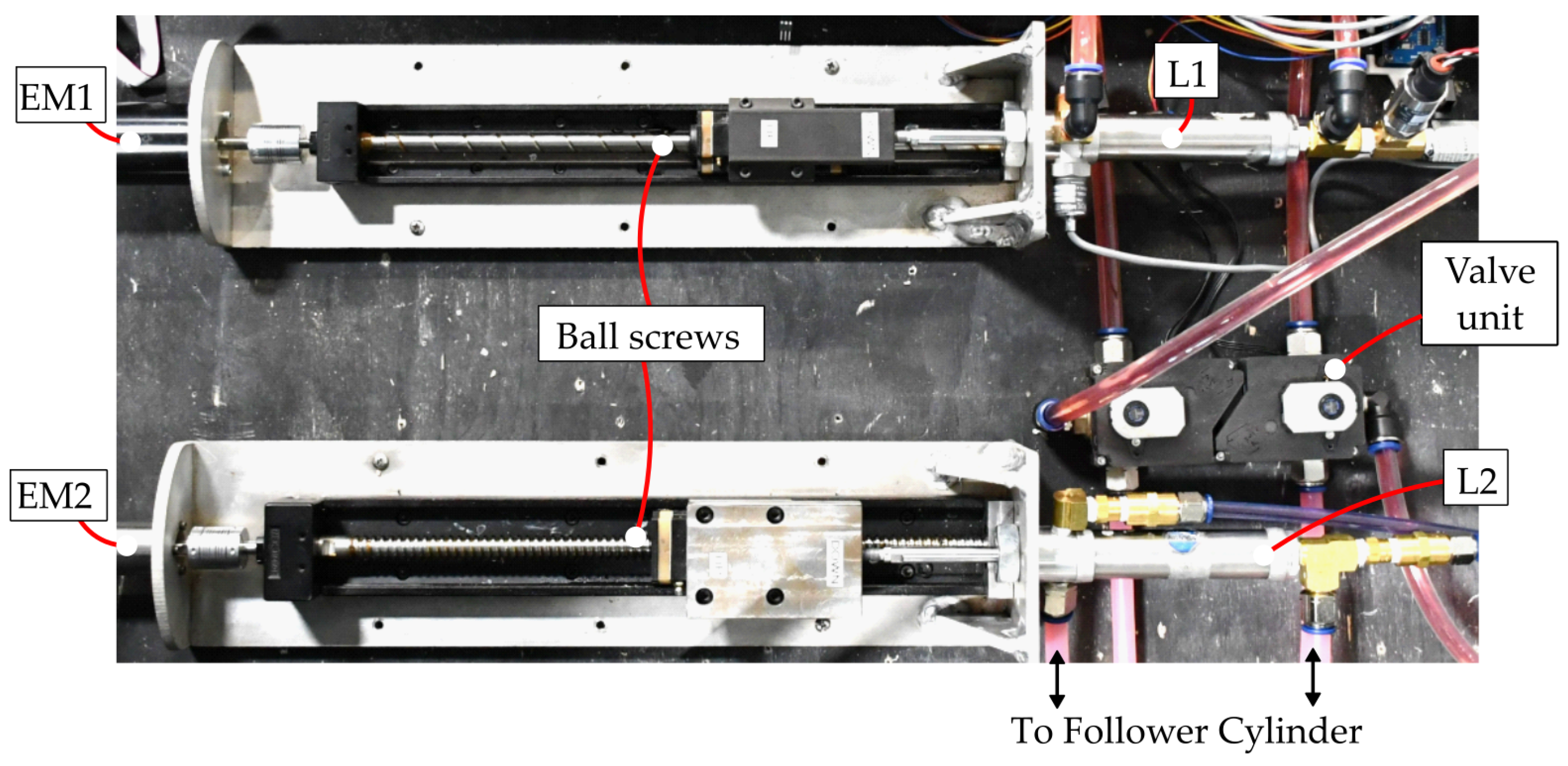
4.1. Prototypes and Test Bench
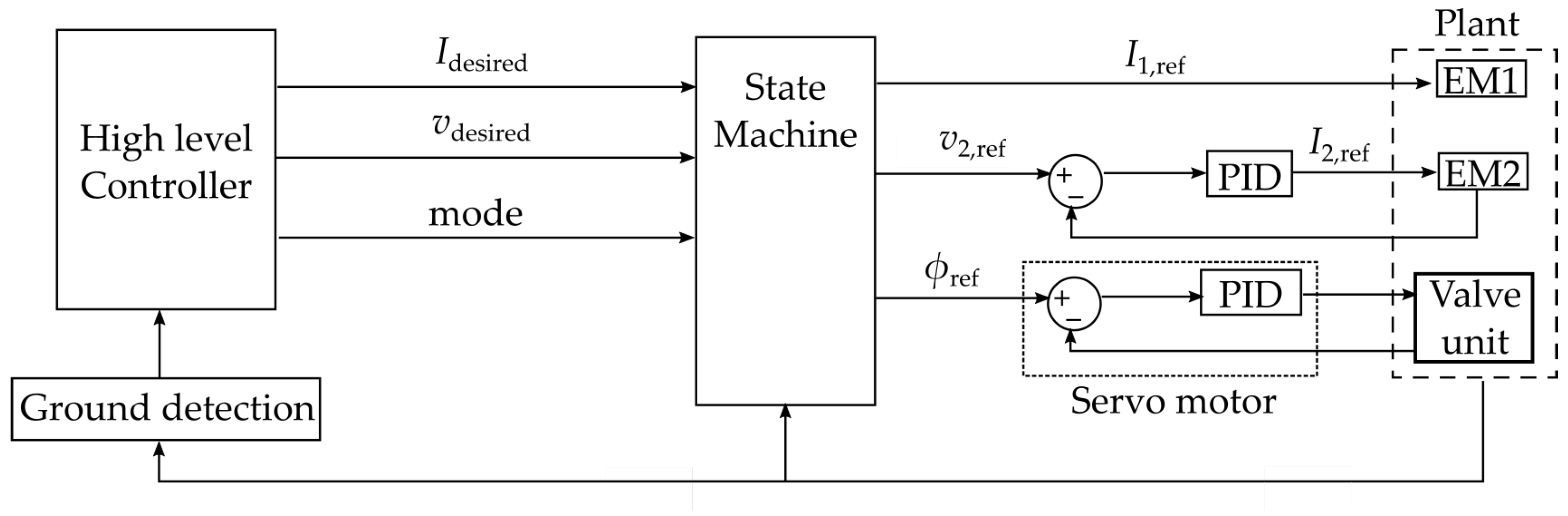
4.2. Control Architecture
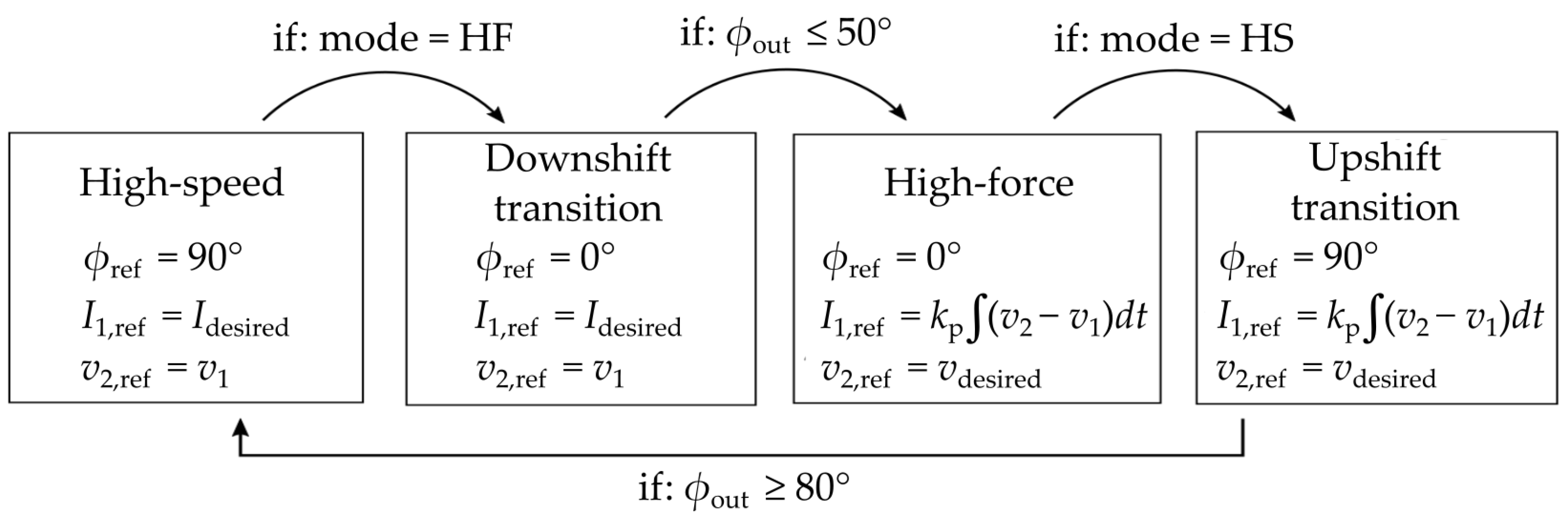
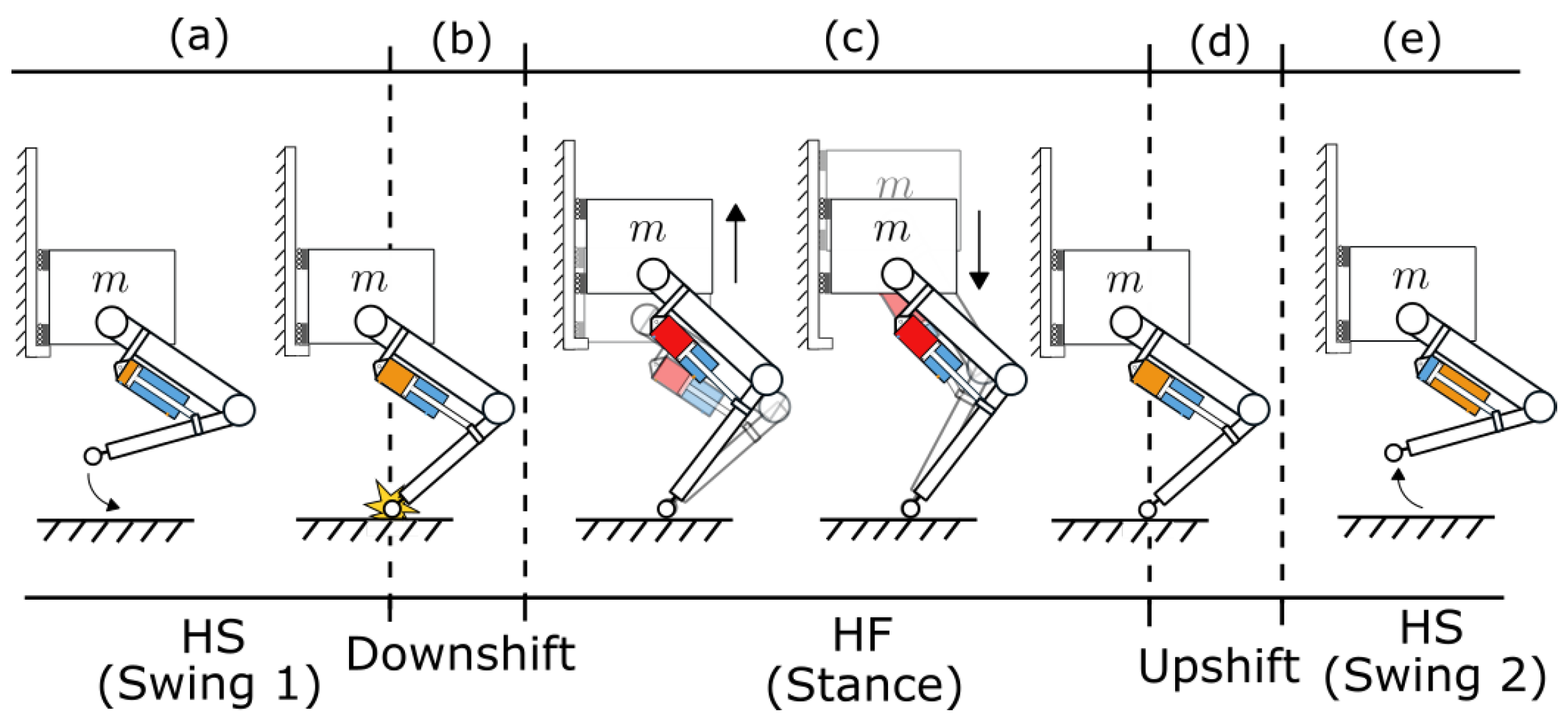
4.3. State Machine and Transitions
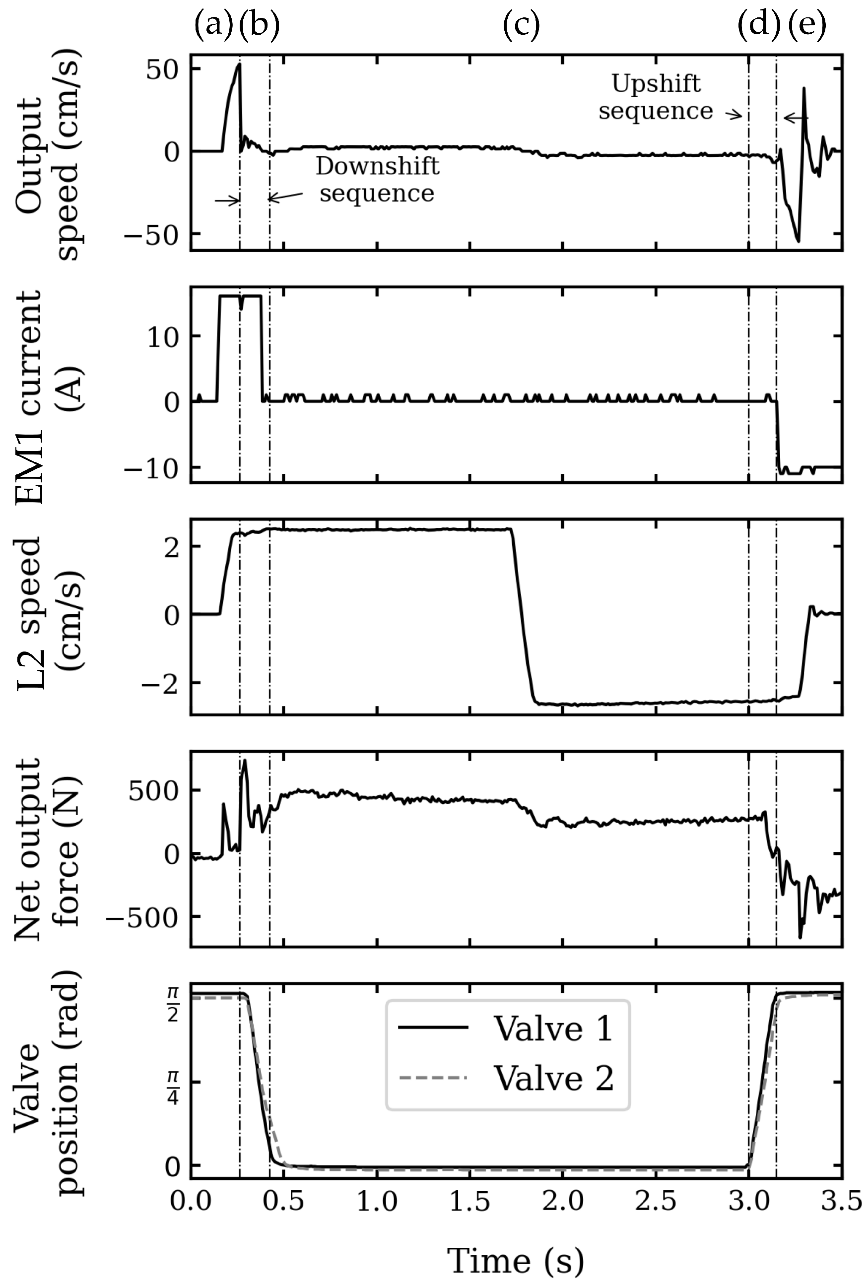
4.4. Experimental Results for Controlling a Robotic Knee
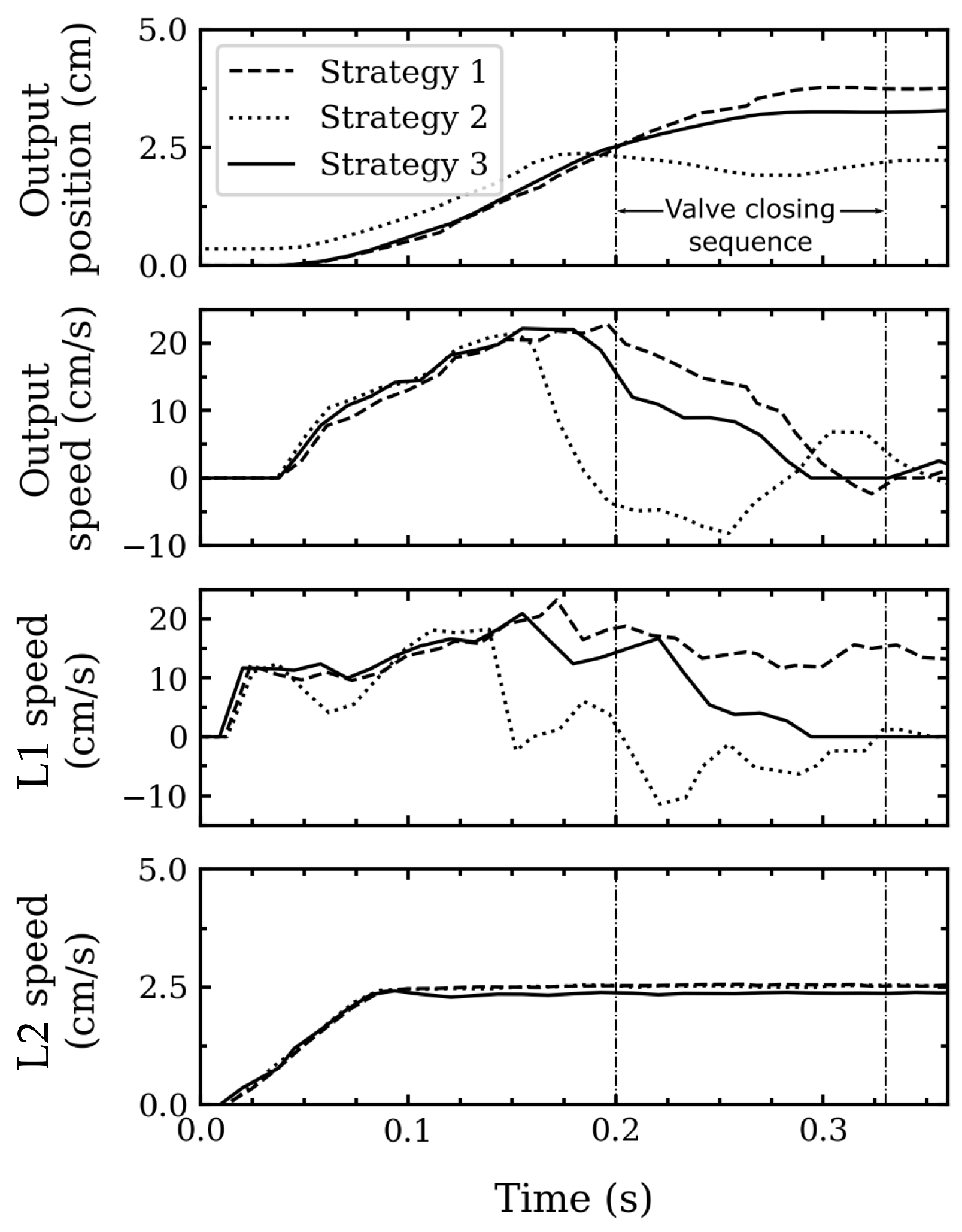
4.4.1. Downshift and Upshift between HS and HF Modes
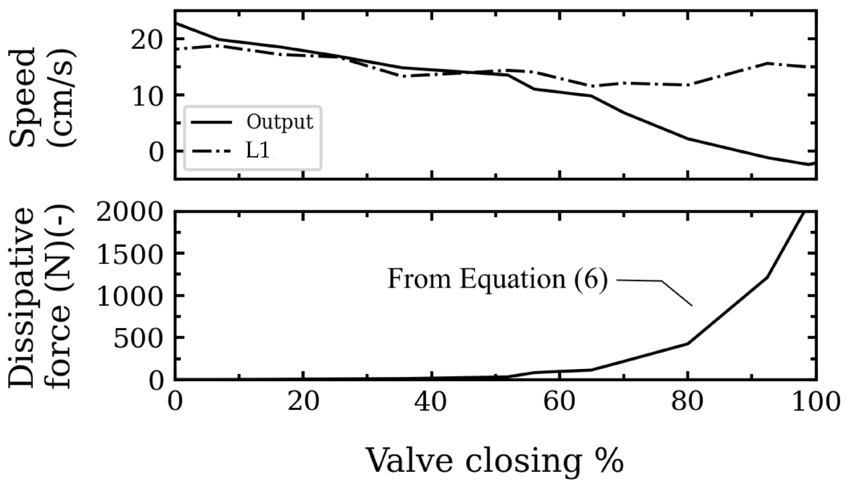
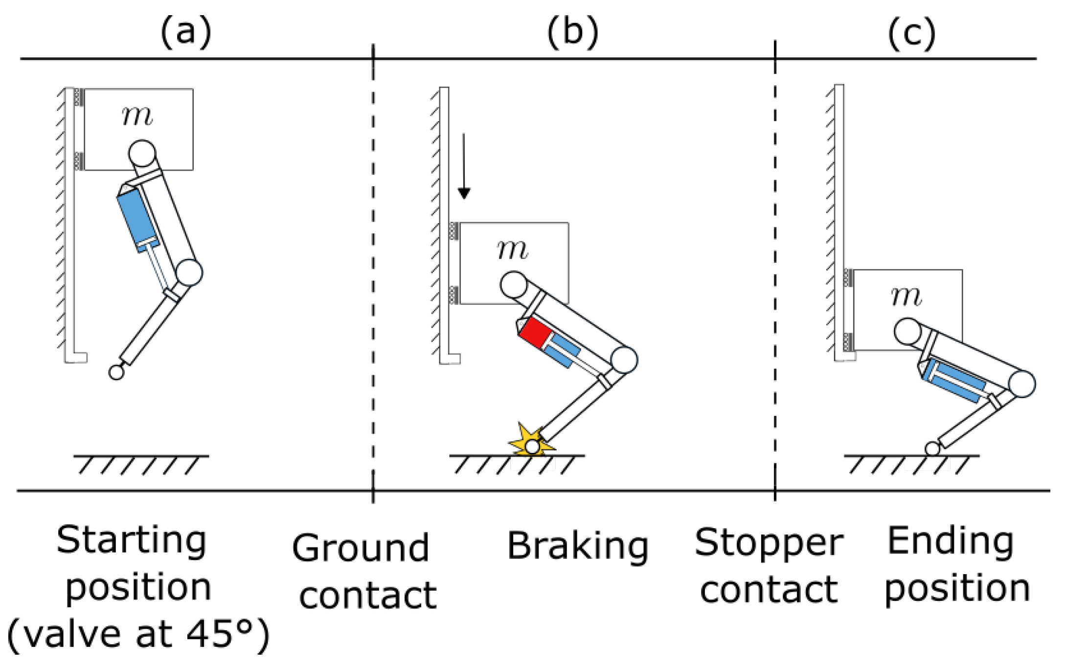
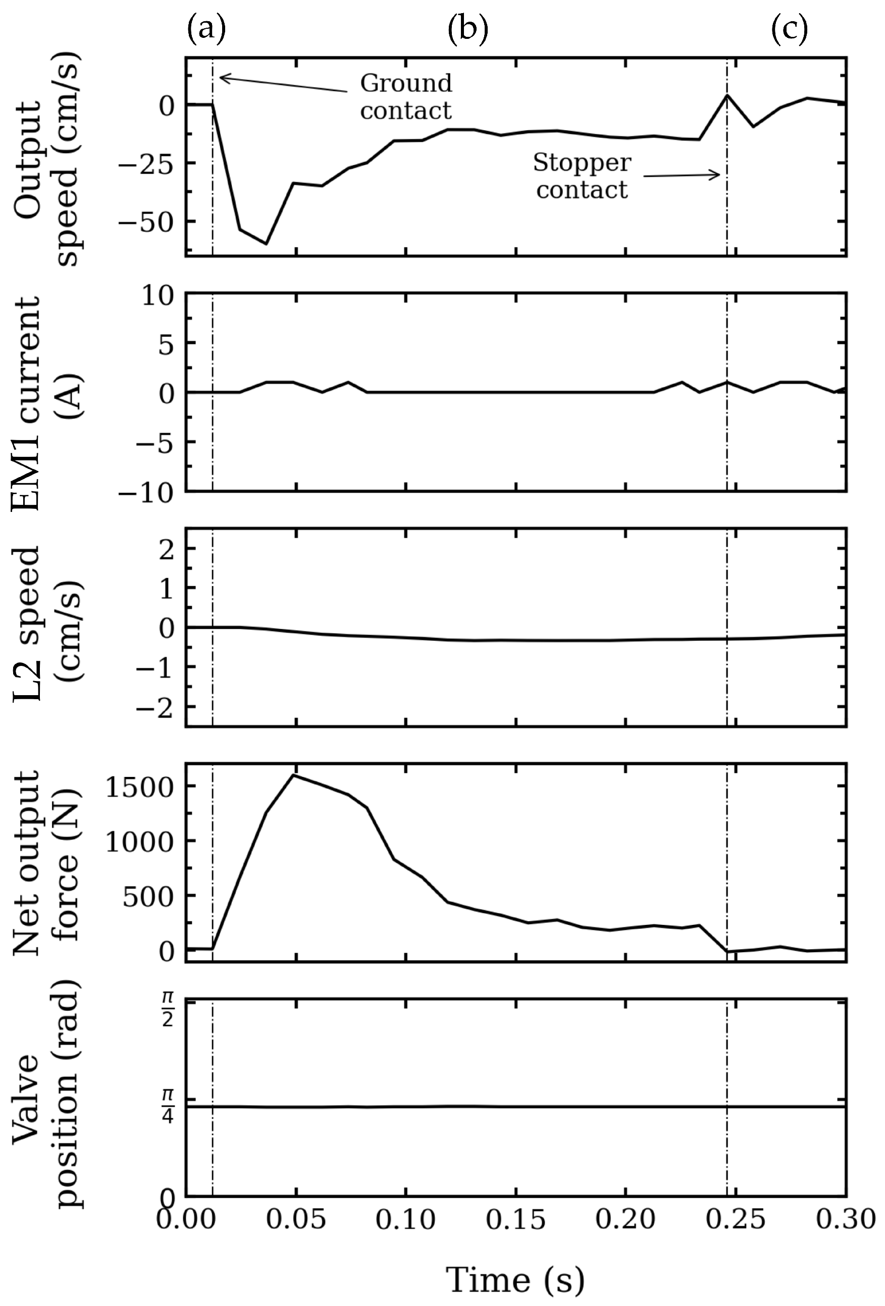
4.4.2. Throttling the Valve for High Braking Forces
5. Conclusions
Supplementary Materials
Author Contributions
Funding
Data Availability Statement
Conflicts of Interest
Abbreviations
| EM | electric motor |
| L | leader (piston/cylinder) |
| HS | high speed |
| HF | high force |
Appendix A. Mass Modeling Using Scaling Laws

| Component and Property y | Scaled from x | k | a | Units | Ref. |
|---|---|---|---|---|---|
| Electric motor (M) | [24] | ||||
| Mass | 0.25 | 0.99 | [35] | ||
| Nominal speed | 487 | −0.54 | |||
| Rotor inertia | 3.06 | 1.46 | |||
| Joule’s coeff. | 17.6 | −1.62 | |||
| Diameter OD | 0.07 | 0.235 | |||
| Ball screw (BS) | [36] | ||||
| Force density | 15,000 | 0 | |||
| Hydraulic cylinder | [37] | ||||
| Force density | 977 | 0.26 |

References
- Sarcos Robotics. Expanding the Limits of Human Potential—Guardian XO. Available online: https://www.sarcos.com/products/guardian-xo-powered-exoskeleton/ (accessed on 19 May 2023).
- Panizzolo, F.A.; Galiana, I.; Asbeck, A.T.; Siviy, C.; Schmidt, K.; Holt, K.G.; Walsh, C.J. A biologically-inspired multi-joint soft exosuit that can reduce the energy cost of loaded walking. J. Neuroeng. Rehabil. 2016, 13, 43. [Google Scholar] [CrossRef] [PubMed]
- Seok, S.; Wang, A.; Otten, D.; Kim, S. Actuator design for high force proprioceptive control in fast legged locomotion. In Proceedings of the 2012 IEEE/RSJ International Conference on Intelligent Robots and Systems, Vilamoura-Algarve, Portugal, 7–12 October 2012; pp. 1970–1975. [Google Scholar] [CrossRef]
- Bledt, G.; Powell, M.J.; Katz, B.; Di Carlo, J.; Wensing, P.M.; Kim, S. MIT Cheetah 3: Design and Control of a Robust, Dynamic Quadruped Robot. In Proceedings of the 2018 IEEE/RSJ International Conference on Intelligent Robots and Systems (IROS), Madrid, Spain, 1–5 October 2018; pp. 2245–2252. [Google Scholar] [CrossRef]
- Girard, A.; Asada, H.H. A two-speed actuator for robotics with fast seamless gear shifting. In Proceedings of the 2015 IEEE/RSJ International Conference on Intelligent Robots and Systems (IROS), Hamburg, Germany, 28 September–2 October 2015; pp. 4704–4711. [Google Scholar] [CrossRef]
- He, J.; Gao, F. Mechanism, Actuation, Perception, and Control of Highly Dynamic Multilegged Robots: A Review. Chin. J. Mech. Eng. 2020, 33, 79. [Google Scholar] [CrossRef]
- Hirose, S.; Yoneda, K.; Arai, K.; Ibe, T. Design of prismatic quadruped walking vehicle TITAN VI. In Proceedings of the Fifth International Conference on Advanced Robotics ’Robots in Unstructured Environments, Pisa, Italy, 19–22 June 1991; Volume 1, pp. 723–728. [Google Scholar] [CrossRef]
- Bell, J.H. A Two-Motor Actuator for Legged Robotics Applications. Ph.D. Thesis, Massachusetts Institute of Technology, Cambridge, MA, USA, 2020. [Google Scholar]
- Jeong, S.H.; Kim, K.S. A 2-Speed Small Transmission Mechanism Based on Twisted String Actuation and a Dog Clutch. IEEE Robot. Autom. Lett. 2018, 3, 1338–1345. [Google Scholar] [CrossRef]
- Lee, Y.; Lee, J.; Choi, B.; Lee, M.; Roh, S.g.; Kim, K.; Seo, K.; Kim, Y.J.; Shim, Y. Flexible Gait Enhancing Mechatronics System for Lower Limb Assistance (GEMS L-Type). IEEE/ASME Trans. Mechatron. 2019, 24, 1520–1531. [Google Scholar] [CrossRef]
- Kim, B.-S.; Song, J.-B.; Park, J.-J. A Serial-Type Dual Actuator Unit With Planetary Gear Train: Basic Design and Applications. IEEE/ASME Trans. Mechatron. 2010, 15, 108–116. [Google Scholar] [CrossRef]
- Verstraten, T.; Furnémont, R.; López-García, P.; Rodriguez-Cianca, D.; Vanderborght, B.; Lefeber, D. Kinematically redundant actuators, a solution for conflicting torque–speed requirements. Int. J. Robot. Res. 2019, 38, 612–629. [Google Scholar] [CrossRef]
- Girard, A. Fast and Strong Lightweight Robots Based on Variable Gear Ratio Actuators and Control Algorithms Leveraging the Natural Dynamics. Ph.D. Thesis, Massachusetts Institute of Technology, Cambridge, MA, USA, 2017. [Google Scholar]
- Khazoom, C.; Veronneau, C.; Bigue, J.P.L.; Grenier, J.; Girard, A.; Plante, J.S. Design and Control of a Multifunctional Ankle Exoskeleton Powered by Magnetorheological Actuators to Assist Walking, Jumping, and Landing. IEEE Robot. Autom. Lett. 2019, 4, 3083–3090. [Google Scholar] [CrossRef]
- Whitney, J.P.; Chen, T.; Mars, J.; Hodgins, J.K. A hybrid hydrostatic transmission and human-safe haptic telepresence robot. In Proceedings of the 2016 IEEE International Conference on Robotics and Automation (ICRA), Stockholm, Sweden, 16–21 May 2016; pp. 690–695. [Google Scholar] [CrossRef]
- Sugihara, K.; Nozaki, T.; Murakami, T. Continuously Variable Transmission by High-speed Path Switching of Linear Electro-hydrostatic Actuator. In Proceedings of the IECON 2019—45th Annual Conference of the IEEE Industrial Electronics Society, Lisbon, Portugal, 14–17 October 2019; Volume 1, pp. 3603–3608. [Google Scholar] [CrossRef]
- Denis, J.; Lecavalier, A.; Plante, J.S.; Girard, A. Multimodal Hydrostatic Actuators for Wearable Robots: A Preliminary Assessment of Mass-Saving and Energy-Efficiency Opportunities. In Proceedings of the 2022 International Conference on Robotics and Automation (ICRA), Philadelphia, PA, USA, 23–27 May 2022; pp. 8112–8118. [Google Scholar] [CrossRef]
- Ozdamar, A.; Gursel, K.T.; Pekbey, Y.; Celikag, B. An Experimental and Numerical Study on Pressure Drop Coefficient of Ball Valves. Int. Energy J. 2007, 8, 301–308. [Google Scholar]
- Ramachandran, H.; Vasudevan, D.; Brahma, A.; Pugazhenthi, S. Estimation of mass moment of inertia of human body, when bending forward, for the design of a self-transfer robotic facility. J. Eng. Sci. Technol. 2016, 11, 166–176. [Google Scholar]
- Elery, T.; Rezazadeh, S.; Nesler, C.; Gregg, R.D. Design and Validation of a Powered Knee–Ankle Prosthesis with High-Torque, Low-Impedance Actuators. IEEE Trans. Robot. 2020, 36, 1649–1668. [Google Scholar] [CrossRef] [PubMed]
- Culver, S.C.; Vailati, L.G.; Goldfarb, M. A Primarily-Passive Knee Prosthesis with Powered Stance and Swing Assistance. In Proceedings of the 2022 International Conference on Rehabilitation Robotics (ICORR), Rotterdam, The Netherlands, 25–29 July 2022; pp. 1–6. [Google Scholar] [CrossRef]
- Veronneau, C.; Denis, J.; Lebel, L.P.; Denninger, M.; Blanchard, V.; Girard, A.; Plante, J.S. Multifunctional Remotely Actuated 3-DOF Supernumerary Robotic Arm Based on Magnetorheological Clutches and Hydrostatic Transmission Lines. IEEE Robot. Autom. Lett. 2020, 5, 2546–2553. [Google Scholar] [CrossRef]
- Carney, M.E.; Shu, T.; Stolyarov, R.; Duval, J.F.; Herr, H.M. Design and Preliminary Results of a Reaction Force Series Elastic Actuator for Bionic Knee and Ankle Prostheses. IEEE Trans. Med. Robot. Bionics 2021, 3, 542–553. [Google Scholar] [CrossRef]
- TQ Systems. ILM Series Framesless Servo Kits. Available online: https://www.tq-group.com/filedownloads/files/products/robodrive/data-sheets/en/DRVA_DB_Servo-Kits_ILM_EN_Rev408_Web.pdf (accessed on 19 May 2023).
- Gizzo, E.; Ackerman, E. Boston Dynamics’ Marc Raibert on Next-Gen ATLAS: “A Huge Amount of Work”. In IEEE Spectrum; IEEE: Piscataway, NJ, USA, 2016. [Google Scholar]
- Buerger, S.P.; Hogan, N. Novel Actuation Methods for High Force Haptics. In Advances in Haptics; InTech: London, UK, 2010; p. 33. [Google Scholar] [CrossRef]
- Lantela, T.; Pietola, M. High-flow rate miniature digital valve system. Int. J. Fluid Power 2017, 18, 188–195. [Google Scholar] [CrossRef]
- Linjama, M. Digital fluid power—State of the art. In Proceedings of the Twelfth Scandinavian International Conference on Fluid Power, Tampere, Finland, 18–20 May 2011; Volume 12, p. 23. [Google Scholar]
- Solutions, S. Latching Solenoid Valves Low Energy. 2021. Available online: https://www.solenoidsolutionsinc.com/specialty-valves/latching-solenoid-valves-low-energy/ (accessed on 19 May 2023).
- Hashemi, S.; Mitchell, H.; Durfee, W.K. Experimentally validated models for switching energy of low pressure drop digital valves for lightweight portable hydraulic robots. In Proceedings of the ASME/BATH 2019 Symposium on Fluid Power and Motion Control, FPMC 2019, Longboat Key, FL, USA, 7–9 October 2019. [Google Scholar] [CrossRef]
- Valworx. 5368/5369 Series Full Port Lead Free Brass 3-Way Ball Valves. Available online: http://cdn.valworx.com/downloads/datasheets/valworx/53685369.pdf (accessed on 19th May 2023).
- Valworx. 5679 Series Electric Actuated 3-Way Ball Valves Product Data Sheet. Available online: https://s3.amazonaws.com/cdn.valworx.com/downloads/datasheets/valworx/5679.pdf (accessed on 19 May 2023).
- Budinger, M.; Liscouët, J.; Hospital, F.; Maré, J.C. Estimation models for the preliminary design of electromechanical actuators. Proc. Inst. Mech. Eng. Part G J. Aerosp. Eng. 2012, 226, 243–259. [Google Scholar] [CrossRef]
- Saerens, E.; Crispel, S.; Garcia, P.L.; Ducastel, V.; Beckers, J.; De Winter, J.; Furnemont, R.; Vanderborght, B.; Verstraten, T.; Lefeber, D. Scaling laws for parallel motor-gearbox arrangements. In Proceedings of the 2020 IEEE/RSJ International Conference on Intelligent Robots and Systems (IROS), Las Vegas, NV, USA, 24 October 2020–24 January 2021; pp. 6339–6346. [Google Scholar] [CrossRef]
- TQ Systems. ILM-E Series Frameless Servo Kits. Available online: https://www.tq-group.com/filedownloads/files/products/robodrive/data-sheets/en/DRVA_DB_Servo-Kits_ILM-E_EN_Rev102_Web.pdf (accessed on 19 May 2023).
- NSK. NSK Precision Machine Components—Ball Screws, 2013. Available online: https://stevenengineering.com/Tech_Support/PDFs/NSK-HB_BALL-SCREWS.pdf (accessed on 19 May 2023).
- KNR Systems Inc. Hydraulic Actuator—RH/LH Series; KNR Systems Inc.: Yongin-si, Republic of Korea.
- THK. Features of the Ball Screws. Available online: https://tech.thk.com/en/products/pdf/en_b15_006.pdf (accessed on 19 May 2023).


Disclaimer/Publisher’s Note: The statements, opinions and data contained in all publications are solely those of the individual author(s) and contributor(s) and not of MDPI and/or the editor(s). MDPI and/or the editor(s) disclaim responsibility for any injury to people or property resulting from any ideas, methods, instructions or products referred to in the content. |
© 2023 by the authors. Licensee MDPI, Basel, Switzerland. This article is an open access article distributed under the terms and conditions of the Creative Commons Attribution (CC BY) license (https://creativecommons.org/licenses/by/4.0/).
Share and Cite
Lecavalier, A.; Denis, J.; Plante, J.-S.; Girard, A. A Bimodal Hydrostatic Actuator for Robotic Legs with Compliant Fast Motion and High Lifting Force. Actuators 2023, 12, 452. https://doi.org/10.3390/act12120452
Lecavalier A, Denis J, Plante J-S, Girard A. A Bimodal Hydrostatic Actuator for Robotic Legs with Compliant Fast Motion and High Lifting Force. Actuators. 2023; 12(12):452. https://doi.org/10.3390/act12120452
Chicago/Turabian StyleLecavalier, Alex, Jeff Denis, Jean-Sébastien Plante, and Alexandre Girard. 2023. "A Bimodal Hydrostatic Actuator for Robotic Legs with Compliant Fast Motion and High Lifting Force" Actuators 12, no. 12: 452. https://doi.org/10.3390/act12120452