Article

A Gripper-like Exoskeleton Design for Robot Grasping Demonstration

Bristol Robotics Laboratory, University of the West of England, Bristol BS34 8QZ, UK
*
Authors to whom correspondence should be addressed.
Actuators 2023, 12(1), 39; https://doi.org/10.3390/act12010039
Submission received: 22 November 2022 / Revised: 13 December 2022 / Accepted: 6 January 2023 / Published: 12 January 2023
(This article belongs to the Special Issue Advanced Technologies and Applications in Robotics)

Abstract

:
Learning from demonstration (LfD) is a practical method for transferring skill knowledge from a human demonstrator to a robot. Several studies have shown the effectiveness of LfD in robotic grasping tasks to improve the success rate of grasping and to accelerate the development of new robotic grasping tasks. A well-designed demonstration device can effectively represent human grasping motion to transfer grasping skills to robots. In this paper, an improved gripper-like exoskeleton with a data collection system is proposed. First, we present the mechatronic details of the exoskeleton and its motion-tracking system, considering the manipulation flexibility and data acquisition requirements. We then present the capabilities of the device and its data collection system, which collects the position, pose and displacement of the gripper on the exoskeleton. The collected data is further processed by the data acquisition and processing software. Next, we describe the principles of Gaussian mixture model (GMM) and Gaussian mixture regression (GMR) in robot skill learning, which are used to transfer the raw data from demonstrations to robot motions. In the experiment, an optimized trajectory was learned from multiple demonstrations and reproduced on a robot. The results show that the GMR complemented with GMM is able to learn a smooth trajectory from demonstration trajectories with noise.

1. Introduction

Industrial robots for manufacturing often rely on pre-programming that specifies a well-defined process or trajectory based on position control [1,2]. The programming method is less robust to changes in the robot workspace, environment and task requirements. The program needs to be adjusted accordingly if the product design or the production process changes, which is time-consuming and error-prone. Moreover, specialist knowledge of robotics and coding is also required for robotic programming [3,4].
Thus, new methods, such as motion planning and learning from demonstration (LfD), which can improve adaptability and reduce programming effort, have received increasing attention in research and applications. LfD is a paradigm that allows robots to learn new skills through demonstrations performed by human operators [5]. Unlike the traditional programming method, LfD allows users to develop new robot tasks through intuitive demonstrations without lengthy programming. This makes the development of robotic tasks faster and more flexible.
More importantly, LfD empowers subject matter experts (i.e., people with a technical background other than robotics) to develop robot tasks combining knowledge from their respective fields [3]. The demonstration tool that affects the demonstration quality is critical in LfD. It is beneficial to develop a device that provides better and more accurate human demonstrations for robot skill learning. Significant research has been done in developing motion-tracking devices for manipulation skill demonstrations.
For different robotic platforms, a range of motion-tracking devices has been developed, including exoskeletons, data gloves, VR devices and motion capture systems. The comparison of these devices is shown in Table 1. Given that this research aims to develop a device to collect grasping demonstrations for a two-finger robot gripper, the exoskeleton is the appropriate solution for such a device. Furthermore, motion tracking devices for LfD can be broadly divided into teleoperation devices and offline data collection devices.
The teleoperation devices record demonstration data and convert it to robot motion commands in real-time, while the offline data collection devices only collect data without having the robot be connected, which facilitates massive data collection and processing. Moreover, teleoperation is a typical application for exoskeletons [6,7]. Sarakoglou et al. [8] presented the HEXOTRAC, a three-finger highly underactuated exoskeleton enabling six-DoF motion tracking of fingertips and force feedback. The exoskeleton consists of three kinematic linkages for the index finger, middle finger and thumb as well as three corresponding DC motors at the first joint of the linkage for force feedback.
The orientation and position of fingers can be calculated by inverse kinematics using the joint angle recorded by the magnetic position encoder. Amirpour et al. [9] presented a hand exoskeleton with a similar linkage design and force feedback function to teleoperate a robot gripper. The hand exoskeleton is advantageous for capturing hand motion because it is adapted to the human hand. Thus, human manipulation skills can be effectively reflected by the exoskeleton. However, existing exoskeletons are usually heavy and bulky due to the force feedback module. Force feedback is essential for teleoperation, but it is not necessary for grasping data collection.
In contrast to the exoskeleton for teleoperation, offline devices typically have a simpler configuration. Osorio et al. [10] used a grasping device to collect a dataset of 37,000 grasping demonstrations. The device consists of a handheld electric gripper and a joystick that control the opening and closing of the gripper. The pose information of the gripper was determined by tracking optical marks on its surface. In [11], a low-cost portable device composed of a servo-control gripper and an RGB-D camera was used for grasping demonstrations. The camera on the device capture gripper-centric videos of grasping demonstrations.
Table 1. Review of devices for hand motion tracking.
DevicesAdvantagesDisadvantagesLiterature
ExoskeletonRepresent human grasping skills; Capable to carry various sensorComplex structure; Heavy[8,9,12]
VR deviceImmersive operationThe generalization from VR devices to robot end-effector[13,14]
Data gloveCompact and lightweightLess applicable to 2-finger grasping[15,16]
Motion capture systemHighly accurateAffected by occlusion, expensive[17]
The RGB-D videos can be processed by visual tracking algorithms to recover the gripper’s trajectory and serve as a training set for a robotic grasping neural network. However, the grasping skill of humans cannot be sufficiently represented by existing offline devices because the grasping is realized by the electric gripper instead of human hands. Therefore, it is promising to develop an offline exoskeleton for a grasping demonstration that combines the advantages of hand exoskeletons and offline grasping devices, which effectively reflects human manipulation skills while having a lightweight and compact design.
In this paper, we present a gripper-like exoskeleton for a grasping demonstration. Our exoskeleton design is a hybrid of existing devices, including teleoperation exoskeletons and offline devices for grasping demonstration. The presented exoskeleton has a parallel gripping mechanism similar to a typical parallel jaw gripper, allowing the user to grasp objects by the thumb and index finger. The mechanism effectively reflects the precise grasping of humans while facilitating the generalization from the exoskeleton to the robot gripper.
Without the need for force feedback, the exoskeleton is lightweight and compact compared to existing exoskeletons, which reduces the burden on the user, particularly when performing multiple demonstrations. We also developed a data collection system for the exoskeleton consisting of a sensing system and data collection software. The position and posture of the exoskeleton and gripper displacement that represented the grasping state can be collected during the grasping demonstration. With the help of the data collection software, it is intuitive for the user to collect data while performing demonstrations.
The contributions of our work include the design of a hand exoskeleton with a similar gripping mechanism to the typical robot gripper, the development of intuitive data collection software that accompanies the exoskeleton, the validation of the data collection system through experiments and the implementation of Gaussian mixture regression (GMR) complemented with a Gaussian mixture model (GMM) to generate a learned trajectory from multiple demonstrations.
The rest of this paper is structured as follows. First, in Section 2, the mechanical design of the exoskeleton is illustrated in detail. Then, Section 3 describes the motion tracking and the data collection system. The principles of GMM and GMR are elaborated in Section 4. In Section 5, experiments were conducted to validate the data collection function of the exoskeleton and to learn an optimised trajectory based on GMM and GMR. The learned trajectory was reproduced on a Franka Emika robot. Finally, our conclusions and future work are presented.

2. Mechanical Design

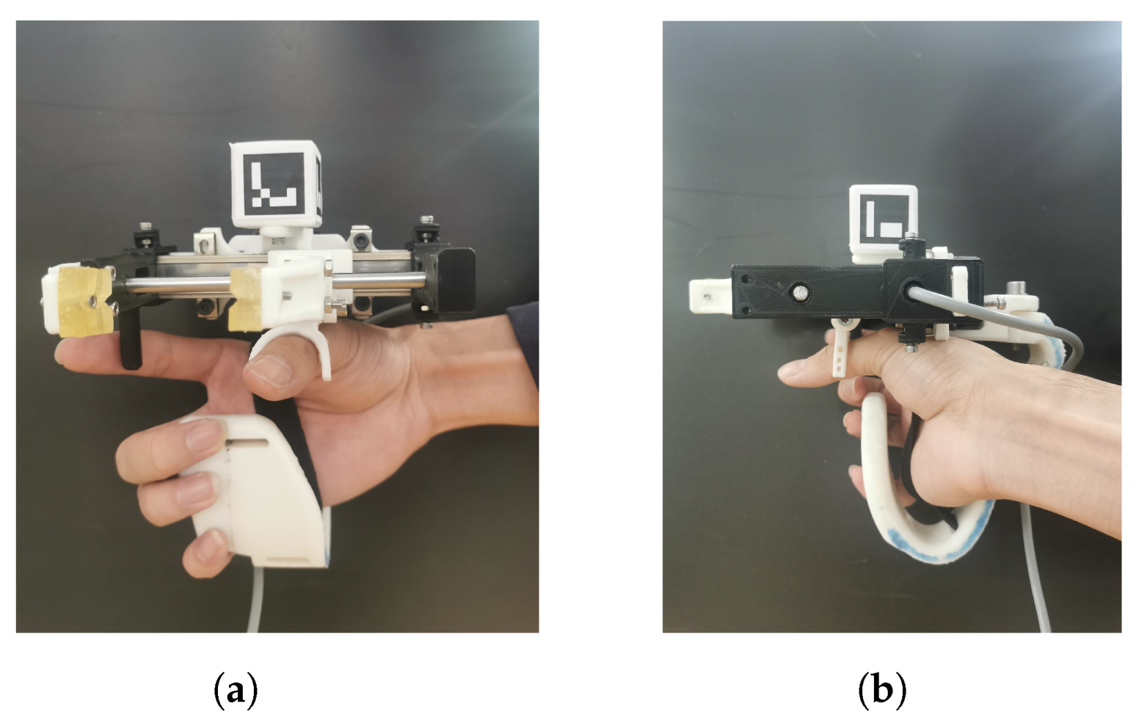
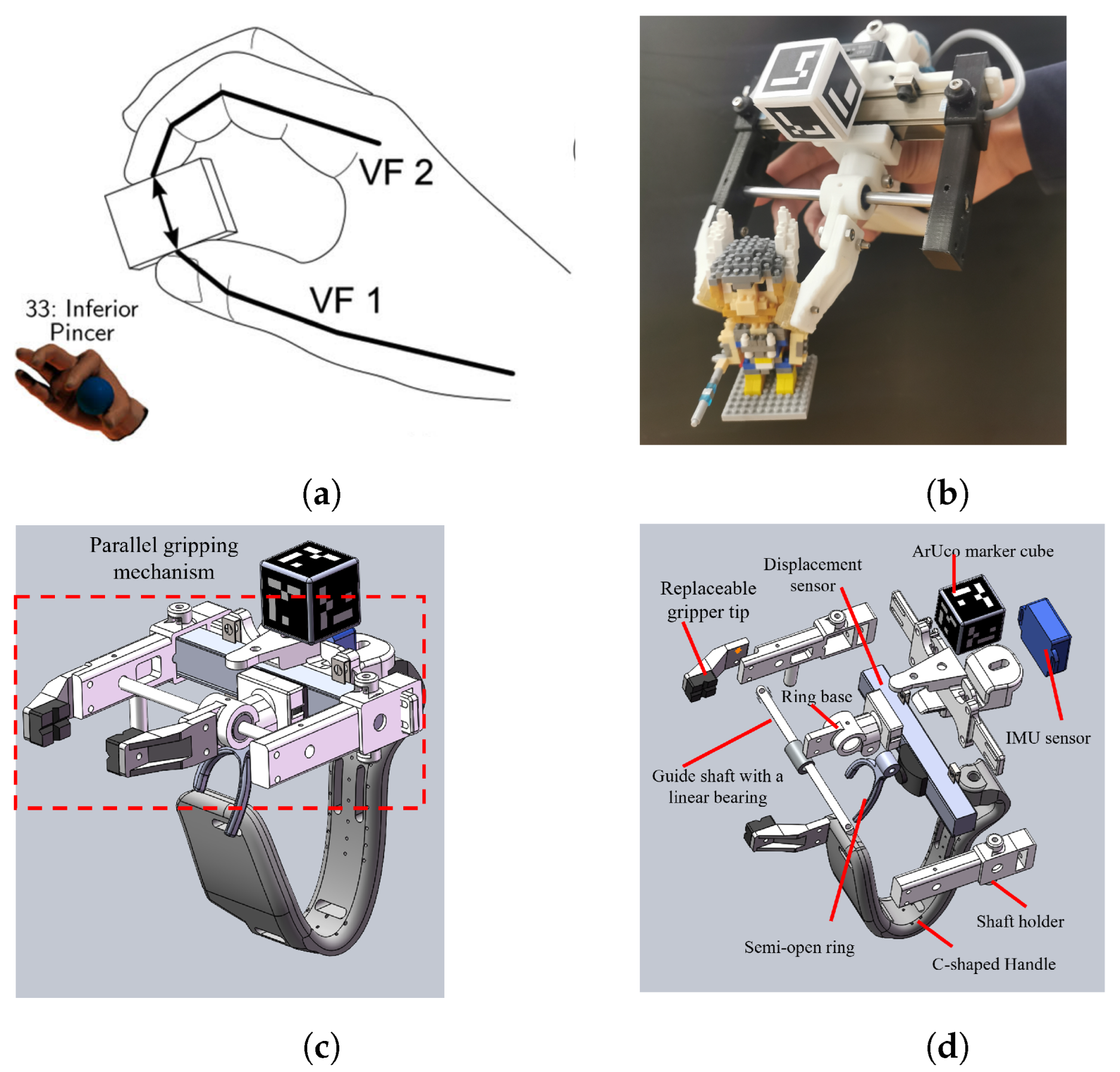
2.1. Design Features

An initial exoskeleton design was reported in previous work [18]. However, its stability and comfort still needed to be improved. During the design modification, we concluded several design features to improve the exoskeleton as follows:
  • The exoskeleton should have a similar configuration to the robot gripper to simplify the correspondence between the robot and the exoskeleton so that it effectively reflects the grasping movements of the user.
  • The usage of the exoskeleton should be intuitive for the user to perform the demonstrations.
  • The exoskeleton should be ergonomic to improve comfort and operational stability.
  • Important data of grasping demonstrations, such as the position and posture of the exoskeleton and the displacement of the gripper should be recorded using various sensing methods and processed by a compatible data collection system.
The improved exoskeleton is shown in Figure 1a,b. It consists of a sensing system, a C-shaped handle and a parallel jaw gripper mechanism similar to the parallel jaw gripper. The parallel jaw gripper is a gripper in which the opposing jaws move in parallel to grip the workpiece. It is often used on various robot platforms. Therefore, we focus on developing an exoskeleton that transfers the demonstration of human grasping to typical parallel jaw grippers, thus, improving the applicability of the exoskeleton.

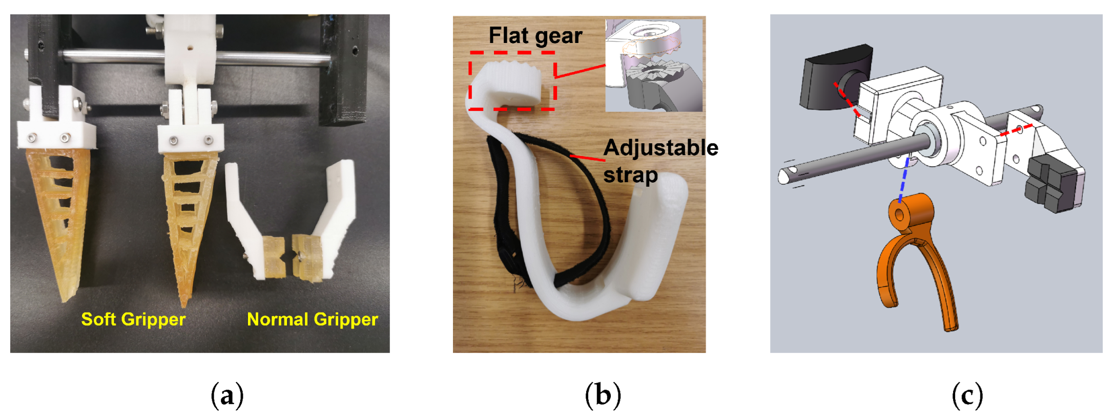
2.2. Parallel Gripping Mechanism

Several studies [19,20,21] on robot grasping based on LfD show that knowledge of the taxonomy of human grasping helps to transfer human motion to robot execution. It is important to understand how humans grasp objects and its kinematic implications for the demonstration of grasping. The human hand has 15 joints, giving it over 20 degrees of freedom [22]. Thus, it is challenging to design an exoskeleton that accurately transfers human grasping to parallel grasping while maintaining a compact and lightweight structure. Most literature classifies human grasp into power, intermediate and precision grasp (PIP). According to the GRASP taxonomy from [23], the parallel gripping motion belongs to the category of inferior pincer grasp under precision grasp. The inferior pincer grasp is a grasp that uses the tips of the thumb and index finger to pick up and grasp objects.
However, in the context of LfD, the transformation of human precision grasping into robot execution still lacks research. Devices that allow human movement intentions to be more effectively reflected in grasping demonstrations are advantageous. Inspired by the inferior pincer grasp, we designed a parallel gripping mechanism actuated by the thumb while the index finger functions as a fixation. As shown in Figure 2a,b, the grasping method of the exoskeleton is similar to the inferior pincer grasp. The mechanism directly converts the inferior pincer grasp into the grasping demonstration. The CAD model of the exoskeleton is shown in Figure 2c,d. The parallel gripping mechanism consists of a guide shaft with two shaft holders, a semi-open finger ring with its base, a central bracket, a displacement sensor and a pair of gripper tips.
The guide shaft parallel to the displacement sensor restricts the motions of the gripper. The displacement sensor and the two shaft holders are mounted on the centre bracket. The thumb of the user’s right hand is placed in the semi-open finger ring, while the index finger is placed next to the fixation bar on the right side of the exoskeleton. The user can pick up and grasp objects by moving the thumb. The thumb-driven gripper is connected to the displacement sensor’s slider via a linear bearing and the ring base to record the displacement data.
Replacing gripper tips according to different kinds of objects is a common scenario in robot grasping. For example, soft grippers are often used when grasping fragile objects. Thus, two kinds of gripper tips were designed for different usages, including a pair of typical gripper tips inspired by the Franka Eimka Robot gripper and a pair of soft gripper tips (Figure 3a) based on the Fin Ray effect [24].

2.3. C-Shaped Handle

Since the gripper is driven by the thumb, We designed a C-shaped handle (Figure 3b) instead of a typical closed loop handle to allow a larger space for finger motion, which ensures a stable grasping demonstration. To increase the subjective comfort-rating [25], we increased the contact area between the handle and inactive fingers (i.e., middle finger, ring finger and tail finger). A strap runs through a positioning slot in the handle to secure the hand to the exoskeleton with an adjustable tightness to suit different users. In addition, the handle and the back of the exoskeleton’s central bracket are contacted via a pair of flat gears as shown in Figure 3b. The flat gears allow the user to adjust the handle to different angles while maintaining stability.

2.4. Design Modification

Compared to previous work [18], several improvements have been made on the presented exoskeleton to improve handiness and wearing comfort as shown in Table 2. In further testing, the adjustment of the gripper during grasping was not desired. Therefore, the gripper was designed to be fixed. The semi-opened finger ring (Figure 3c) is slightly larger than the previous one and better fits the thumb shape of the different users because of sufficient space for adjustment. Accordingly, the base of the finger ring was modified accordingly for a compact design. The handle was changed from a closed design of a scalloped shape to a semi-open design to avoid obstructing the thumb motion. The contact area of inactive fingers and handles also increased as the width of the handle increased.

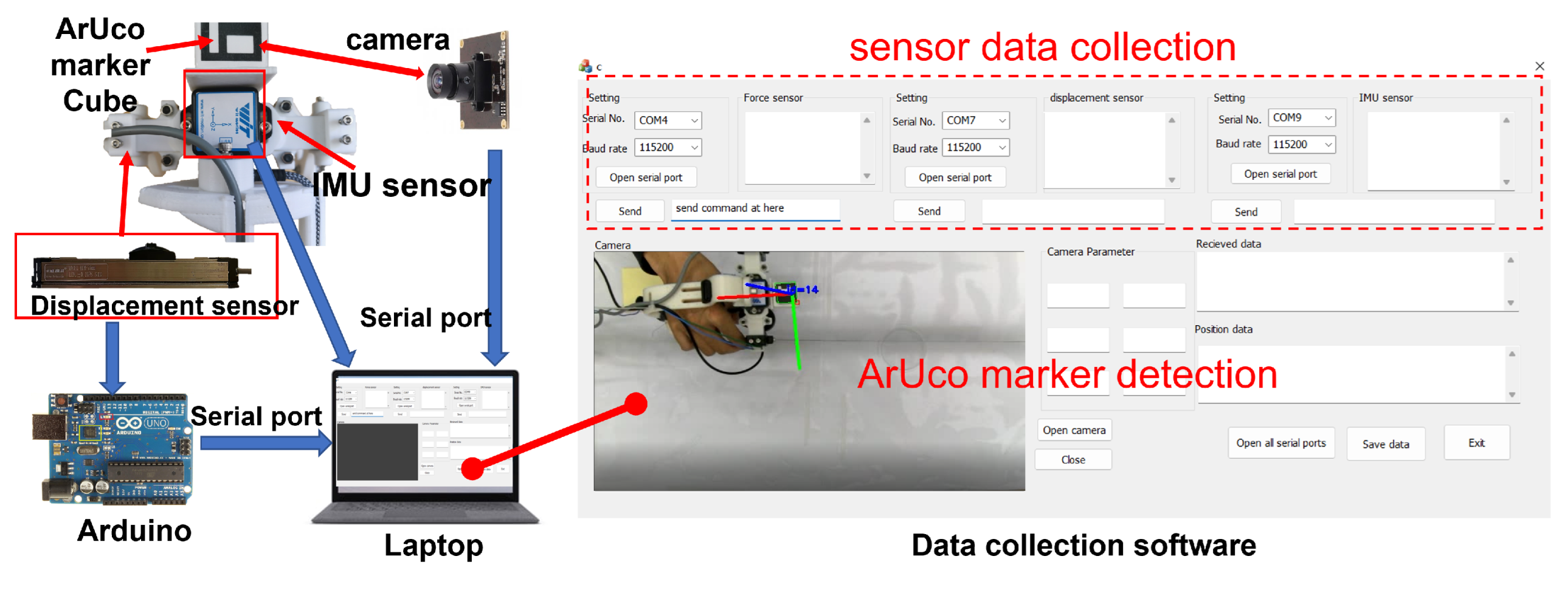
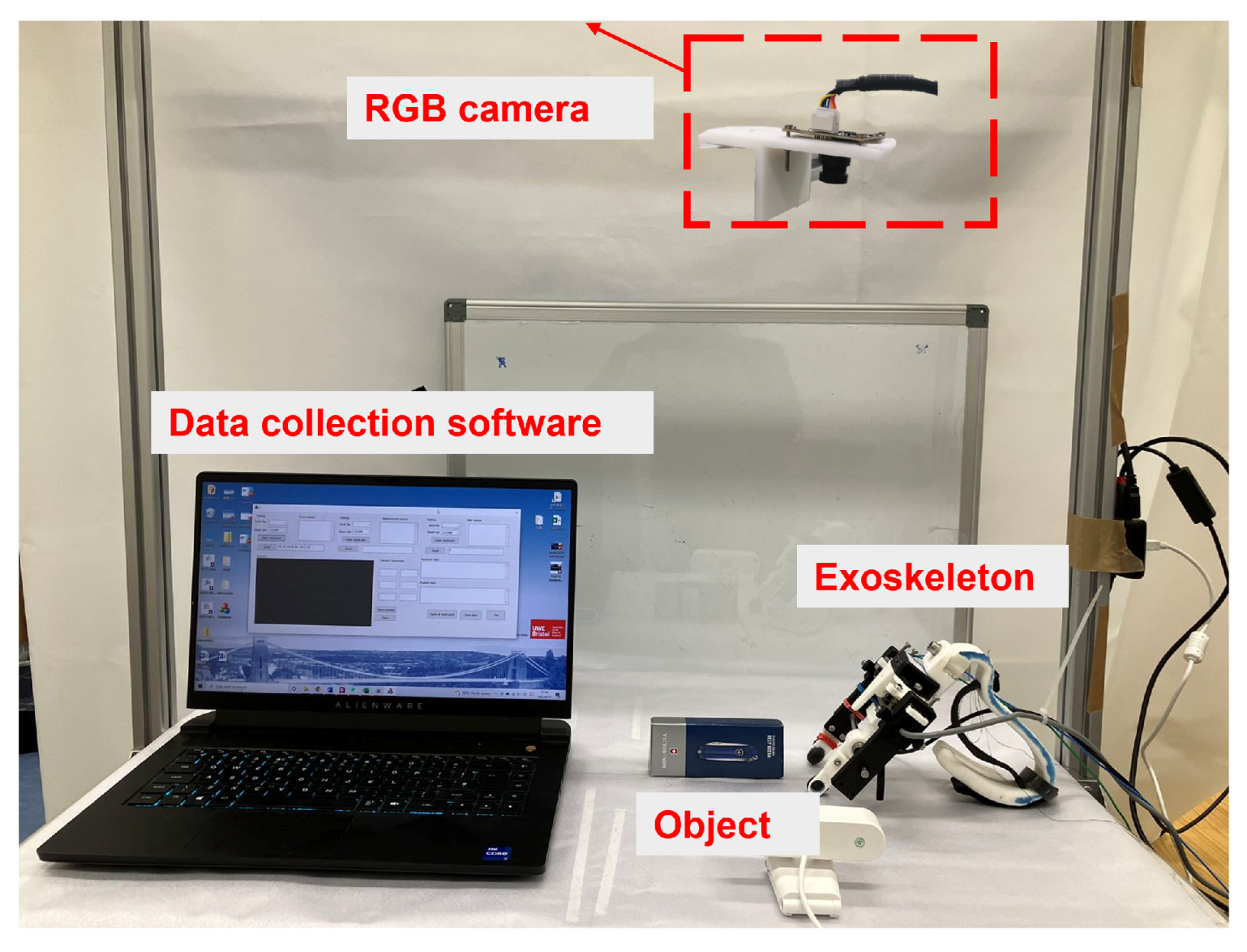
3. Motion Tracking and Data Collection System

In robot grasping, the position and posture of the robot gripper and the distance between the gripper jaws are basic information that determines the motion state of robot grasping. Therefore, as a demonstration device, the exoskeleton was designed to collect the aforementioned data. The sensing system of the exoskeleton consists of a linear displacement sensor (KFM75, Miran), an AHRS IMU sensor (BWT901BLECL5.0, Witmotion) and an ArUco maker cube.

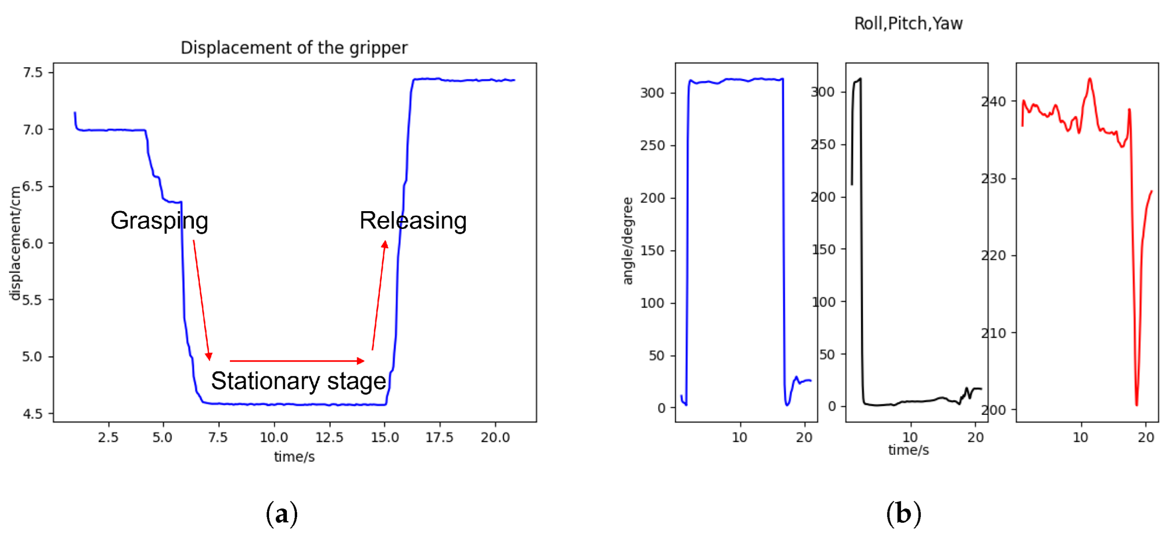
3.1. Gripper Displacement

The linear displacement sensor is a slider-type displacement sensor. It measures the displacement of the slider that moves linearly. The thumb-driven gripper is connected to the slider in the parallel gripping mechanism. Therefore, the displacement of the gripper can be measured. The displacement sensor has a length of 10 cm with a measurable distance range of 0 to 7.5 cm and a resolution of 0.05 to 0.1 mm, which is sufficient for a grasping demonstration.

3.2. Pose Estimation

IMU sensor is a widely used sensor to obtain pose information. Typically, the combination of different sensors improves the accuracy of the inertial measurement. The AHRS IMU sensor in the exoskeleton comprises a gyroscope, an accelerometer and a geomagnetic field sensor. The z-axis angle is calculated based on the geomagnetic field sensor to eliminate the accumulated error caused by the drift of the gyroscope integration. In addition, its onboard digital filtering and sensor fusion algorithm provides an accurate and stable angle estimation (roll, pitch and yaw). The roll and pitch accuracy is 0.05°, while the yaw accuracy is 1° after magnetic calibration. Figure 4 illustrates the data collected from the displacement sensor and IMU sensor, where the change in the grasping state can be seen.

3.3. Position Estimation

The position estimation is obtained by tracking the position of the ArUco marker cube. Position estimation is of great importance for recording the trajectory of grasping demonstrations. The basis of vision-based position estimation is to compute the correspondence between points in the real world and their 2D visual projection. Fiducial markers, particularly binary square fiducial markers, are frequently used to facilitate the estimation. The ArUco marker is a well-known binary square fiducial marker for pose estimation, which was first proposed in [26]. This is a cost-efficient solution to record the position of grasping demonstrations compared to other methods, such as optical markers.

3.4. Data Collection

The data collection system is illustrated in Figure 5. The displacement sensor and the IMU sensor were mounted on the centre of the exoskeleton. The ArUco marker cube was mounted on the top of the exoskeleton to avoid occlusion. Its five visible faces were attached with ArUco markers. In this way, the marker cube could be detected from different directions. We also developed a host software with an intuitive user interface for data collection and initial data processing. The software has multiple functionalities that are essential for grasping data collection. Its interface can be divided into two major modules: the sensor data collection module and the ArUco marker position estimation module.
In the sensor data collection module, the displacement sensor and the IMU sensor are communicated with the software based on serial communication protocol [27]. In the ArUco detection module, video frames captured by the camera are processed to detect the ArUco marker and calculate its position to the camera coordinate. The tracking of the ArUco marker can also be displayed on the screen. During the demonstration, the grasping data collected from different sources with various formats can be decoded and visualised in the user interface.
The exoskeleton is a multiple-sensor system. Different sensors have different clock times and sampling rates, which causes subsequent data processing problems. Only the synchronised data should be converted to robot execution; otherwise faulty movements will result. Therefore, data synchronisation is an essential aspect of data collection. In a preliminary test, the sampling frequencies of the displacement sensor and IMU sensor were near 800 and 200 Hz, respectively. The frequency of the position estimation of the ArUco marker was lower, limited by the frame rate of the real-time captured video and the running time of the ArUco marker tracking program.
Thus, the data collection software used a reference clock with a millisecond resolution to synchronise the data. Each data point is attached with a time stamp. In the subsequent processing, data from different sources are aligned and converted to the same frequency by interpolation padding based on their time stamps.
To facilitate grasping demonstrations, we built an experimental platform (Figure 6) consisting of the exoskeleton, a laptop running the data collection software and an RGB camera (3840 × 2160 pixels, Autofocus 100 degree lens) on the top for ArUco marker detection. The object to be grasped was placed on the board of the platform. In addition, the measurement of the camera was calibrated using the MATLAB Camera Calibrator App [28]. First, the camera took 15 to 20 images of a typical checkerboard calibration pattern in different positions and orientations. Based on these input images, the calibrator App can calculate the camera intrinsic, which represents the focal length and optical centre of the camera. The intrinsic camera enables the relative location between the ArUco marker and the camera to be computed in word units.

4. Learning from Demonstration

Movement representations play an important role in encoding skills from human demonstrations. This breaks down the demonstrations into “building blocks” for synthesising more complex movements. A common approach for movement representation is to build a regression model. Typical representation methods include weighted least squares, locally weighted regression (LWR), dynamical movement primitives (DMP) and Gaussian mixture regression (GMR) [29].

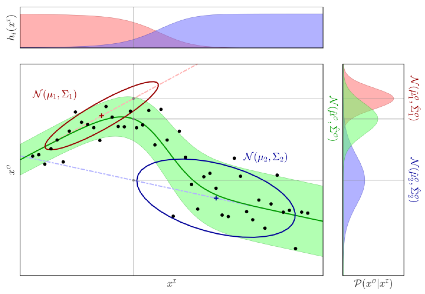
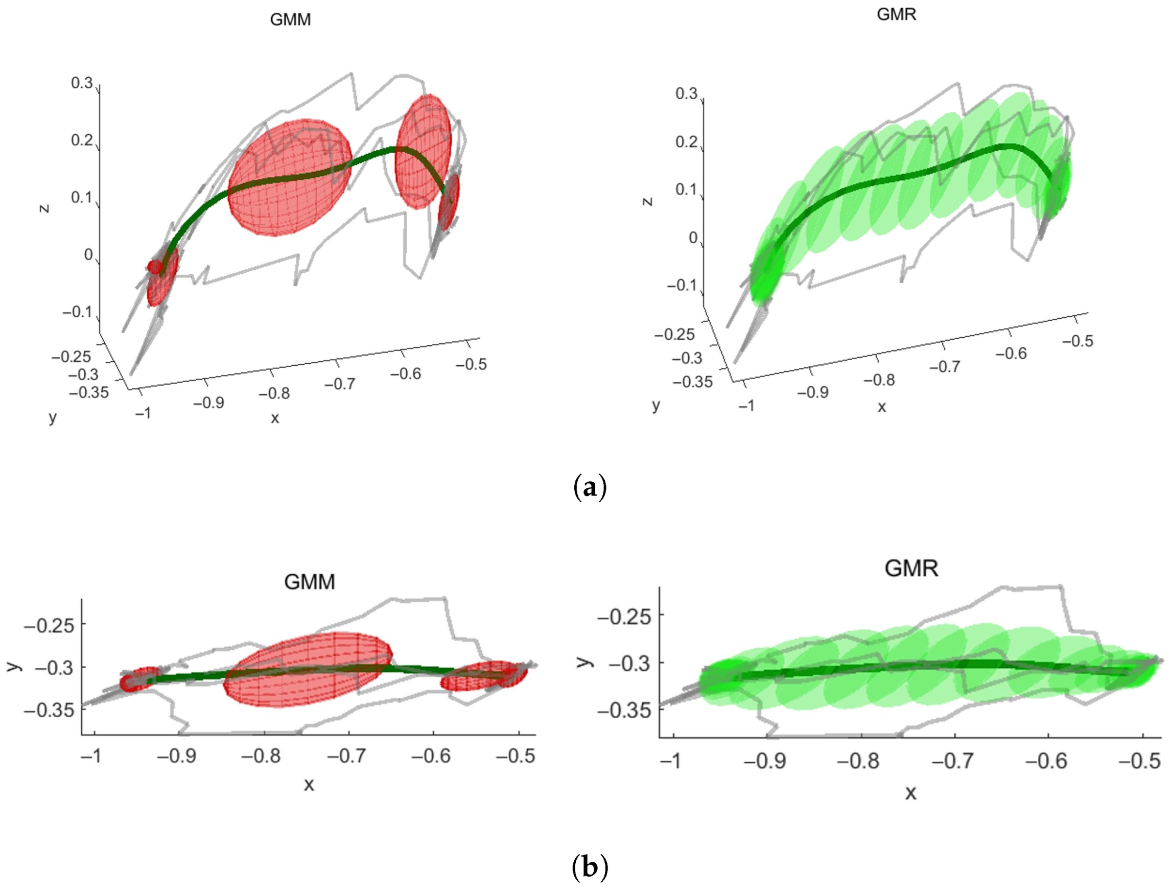
4.1. Motion Representation Encoded by GMM and GMR

GMR is an effective method for motion representations. It can generate a smooth regression curve (i.e., smooth trajectory reproduction) with good robustness from multiple demonstrations and is robust to noise in the data [29,30]. An intermediate step in GMR is using the Gaussian mixture model (GMM) to calculate the joint probability density of data from multiple demonstrations. The regression function can be obtained by GMR based on the joint density model. In addition, the calculation time of GMR is independent of the amount of data, as only the regression of the density model is calculated, rather than each data point, allowing for fast convergence of the regression.

4.1.1. Gaussian Mixture Models

Gaussian mixture model (GMM) is a method to extract motion features from human demonstrations, which is composed of several probability density functions with unknown parameters in a multi-dimensional space. The probability density function of GMM is:
P ( X , Θ ) = k = 1 K p k N X | μ K , k ,
where K is the number of components (i.e., Gaussian functions) in GMM, p k is the prior information (i.e., the probabilistic weight of the kth Gaussian functions), N ( X | μ K , k ) is the Gaussian distribution of the observations, in which μ k is the centre (i.e., the mean vector) and k is the covariance matrix. In trajectory learning based on GMM and GMR, we collected data from multiple trajectory demonstrations. After prepossessing the data, we obtained an N normalized sample sequence: X = { x t | t = 1 N } . The Θ = { { p 1 , μ 1 , 1 } , { p 2 , μ 2 , 2 } { p K , μ K , K } } representing the entire set of unknown parameters can be approximated by the Expectation–Maximization (EM) method.
The principle of GMM is to find the most probable Gaussian distribution mixture that best represents multiple demonstrations. Thus, the maximum likelihood estimate of the set of uncertain parameters is the goal. This is represented by:
Θ * = a r g m a x Θ [ P ( X , Θ ) ] ,
The Θ * can be determined by using the expectation step (E-step) and maximization step (M-step) iteratively. The probability that a given point is characterised by a certain model component is known as responsibilities in a GMM. The responsibilities of the model are computed by the E step, which is expressed by:
γ t , k = p k N x t | μ k , k i = 1 K π i N ( x | μ i , i ) ,
where t = 1 N , k = 1 K . The responsibilities h t , k are then used in M step to calculate the parameters set Θ * , which maximises the probability distribution function in Equation (8). Model parameters μ k , p k , k as below are the calculated by the M-step:
μ k = t = 1 K γ t , k x t t = 1 K γ t , k ,
p k = 1 N t = 1 K γ t , k ,
k = t = 1 N γ t , k ( x t μ k ) ( x t μ k ) T t = 1 N γ t , k
In the iteration of the EM method, model parameters { μ k , p k , k } will converge to their maximum likelihood until the responsibilities γ become stable.

4.1.2. Gaussian Mixture Regression

The Gaussian mixture model can then be used to determine the predicted features based on the input features. The I and O notation represent the input and output, respectively. In grasping trajectory learning, the output feature x O is the learned trajectory, and the input features x I are multiple demonstration trajectories. GMR calculates the conditional probability distribution P ( x O | x I , Θ ) of the learned trajectory by modelling the joint probability distribution P ( x I , x O | Θ ) and the marginal distribution P ( x I | Θ ) . In joint probability distribution, the mean vector μ k and covariance matrix k of the k = 1…K Gaussian are denoted as:
μ k = μ k I μ k O , k = k I k I O k O I k O .
The conditional distribution P ( x O | x I , Θ ) for the learned trajectory given multiple demonstrations x I is a Gaussian mixture with its mean vector μ k ^ , covariance matrices ^ k and probabilistic weight p k ^ . The notation ^ is to distinguish the parameters from those of Gaussian mixture models. The conditional distribution is formulated as:
P ( x O | x I , Θ ) = k = 1 K p k ^ N μ ^ k , ^ k ,
Based on the model parameters of GMM (i.e., Θ = μ k , k , p k ), parameters { μ k ^ , ^ k , p k ^ } of the conditional distribution are calculated as bellow:
μ ^ k = μ k O + k O I k I 1 ( x t I μ k I ) ,
^ k = k O k O I k I 1 k I O ,
p k ^ = p k N x I | μ k I , k I i = 1 K p k N ( x I | μ k I , k I ) ,
The Gaussian distribution N is computed by:
N x t I | μ k I , k I = ( 2 π ) D / 2 | k I | 1 / 2 e x p 1 2 ( x t I μ k I ) T k I 1 ( x t I μ k I ) ,
Subsequently, a mixture of Gaussians as a single Gaussian can be approximated by moment matching of the means and covariances. The output distribution has the following parameters:
μ ^ O = i = 1 K h k ^ μ ^ k ,
^ O = i = 1 K h k ^ ( ^ k + μ ^ k μ ^ k T ) μ ^ k μ ^ k T .
Figure 7 shows an example of the GMR process. The responsibilities h k ^ of two Gaussians are shown at the top of the Figure. The black dots in the bottom left plot are the input data points clustered into two Gaussian distributions denoted by the red and blue ellipse. In the plot on the right side, the red and blue distributions indicate the conditional distributions of the output as computed by Equation (8). The peak of the conditional distribution represents the mean of the distributions. Finally, the predicted trajectory (i.e., the green curve) is determined by combining the mean of the conditional distributions and the responsibilities as expressed by Equation (13).

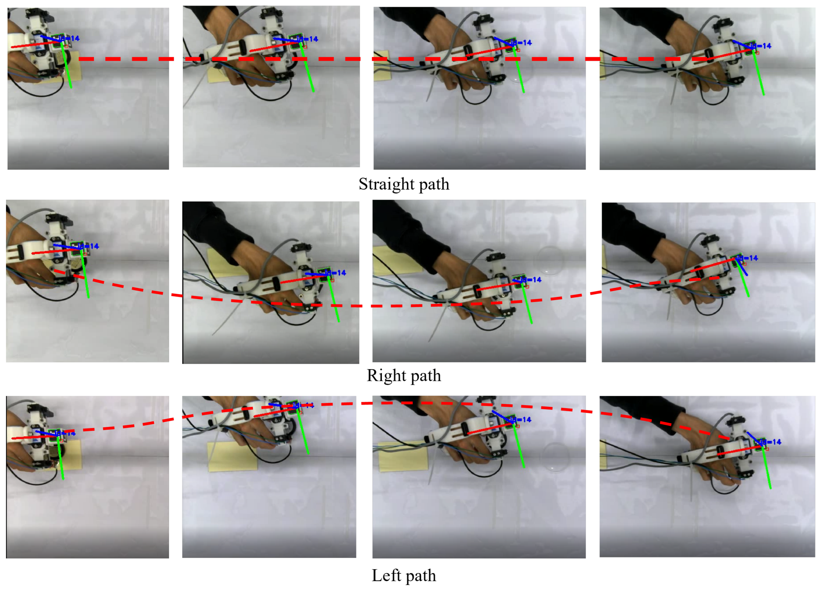
5. Trajectory Learning and Reproduction

We conducted a trajectory learning and reproduction experiment to test the data collection function of the exoskeleton and apply GMR to learn an optimised grasping trajectory from multiple demonstrations.

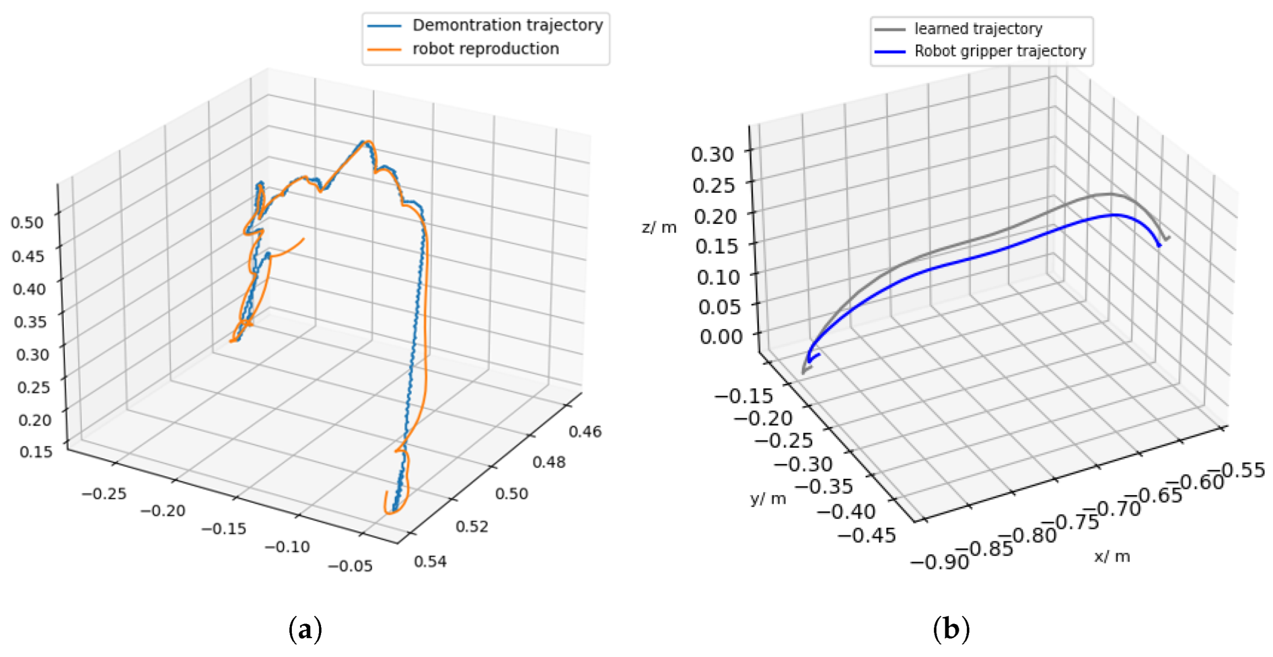
5.1. Trajectory Learning Based on GMR

The first step for trajectory learning based on GMR is to collect multiple demonstration trajectories. Figure 8 shows that the operator wearing the exoskeleton grasped and placed the object via three different paths. Four trajectories in total (i.e., two for the straight path, one for the right path and one for the left path) were collected. During the data collection, the position of the exoskeleton was tracked and recorded by the data collection software. Thus, the motion tracking of the ArUco marker (i.e., the three axes of the marker) on the exoskeleton can be clearly seen in the Figure.
Figure 9a,b illustrates the trajectory generation result based on the Gaussian mixture model and Gaussian mixture regression. The GMR algorithm was tested and performed with the pbdlib function library [29] in MATLAB. In Figure 9, The four trajectories shown in grey were collected from human demonstrations. It can be seen that there are some fluctuations in the demonstration trajectories, which are caused by the perturbations of human motion and the inherited noise in the data collection system. In GMM, the red ellipse indicates a concentration of Gaussian distributions of demonstration trajectories, representing the joint probabilistic density of trajectories. The regression function was then computed by the GMR to generate a smooth trajectory (i.e., the trajectory in green colour). Compared to the demonstrations, the learned trajectory effectively reduced the fluctuation in the demonstration trajectories, resulting in an optimised trajectory.

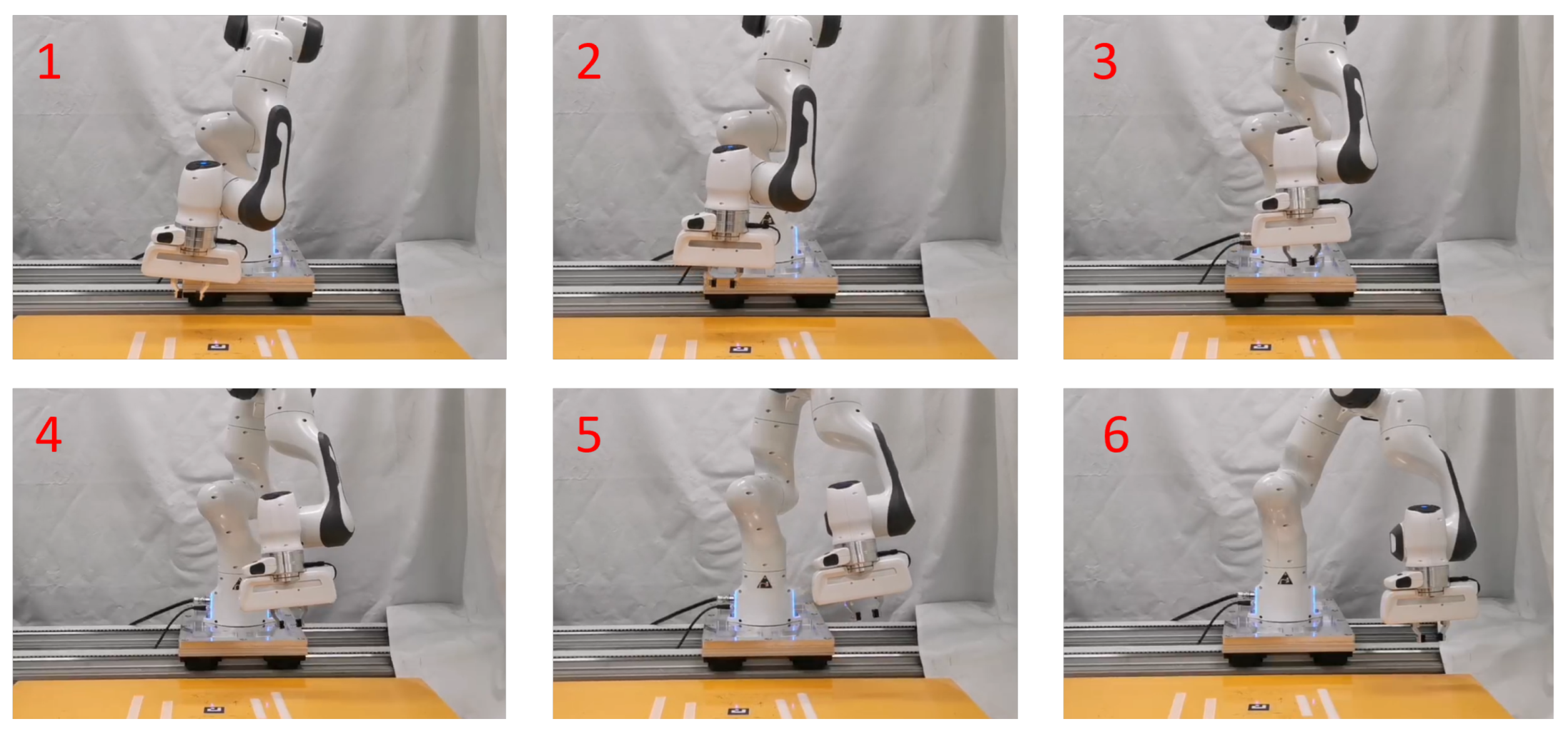
5.2. Trajectory Reproduction on Franka Emika Robot

The optimized trajectory was converted to executable robot command and then reproduced by a Franka Emika Robot as shown in Figure 10. To facilitate the trajectory comparison, the position data of the robot gripper was recorded by the robot onboard sensor during the trajectory reproduction.
Figure 11 compares the results of trajectory reproduction based on a single demonstration and trajectory reproduction based on GMR trajectory learning. The trajectory reproduction based on a single demonstration has obvious fluctuations, whereas the trajectory reproduction based on multiple demonstrations is smooth. A trajectory with fewer fluctuations is energy-efficient and safe for robot movement. In addition, we reduced the stiffness of the robot control for trajectory reproduction based on multiple demonstrations, making the robot less responsive. Despite this, the robot was still able to follow the trajectory, which shows that the learned trajectory is easier to follow.

6. Conclusions and Future Work

In this paper, we presented a hand exoskeleton for grasping demonstration. The exoskeleton had a similar parallel gripping mechanism to a typical parallel jaw gripper. The gripping mechanism design considered the taxonomy of human grasping, which helps to transfer human motion into robot execution. The presented exoskeleton design also combines the strength of the existing exoskeleton for teleoperation and devices for grasping demonstration. It effectively represents human grasping skills while maintaining a lightweight structure.
Furthermore, the replaceable gripper tips enabled the exoskeleton to adapt to various situations, whereas the gripper of existing grasping demonstration devices is usually not replaceable. Compared to the previous design, several design improvements, such as a C-shaped handle design and semi-open finger ring, were made to the exoskeleton to improve its stability and comfort. In the data collection system, several cost-efficient motion-tracking approaches were integrated into the exoskeleton. We also developed data collection software with multiple functionalities to adapt the sensing system to facilitate the data collection.
In the experiment, the operator collected several demonstration trajectories for trajectory learning and reproduction. The GMR combined with GMM as a motion representation approach was applied for trajectory learning. The results show that the method could compensate for fluctuations in human demonstrations, resulting in a smooth trajectory. Although the GMR method significantly refined the trajectory, the accuracy of the data collection still needs to be improved.
In future work, further experiments, such as robot grasping and assembly, can be conducted. More functionalities of the exoskeleton can also be realized via the replaceable gripper tips, such as using the soft gripper to demonstrate fruit picking. The material properties of the various fruits are deformable and compliant, which presents a challenge for robotic fruit picking and sorting. In [31], a learning policy based on LfD was used to teach robots handling food raw materials. Using the hand exoskeleton to transfer dexterous manipulation skills from skilled workers to robots has great potential in the agriculture and food industry.
In addition, measuring object size while grasping is also a benefit of the hand exoskeleton because of the displacement sensor. Furthermore, it is convenient for the exoskeleton to carry different sensors, such as force sensors and tactile sensors, because of the replaceable gripper tips. Multiple sensor measurements can be used in robot skill learning to improve the robot grasping success rate. In addition, the lightweight and compact design of the exoskeleton reduces the burden on the user during prolonged use. Therefore, it is possible to create a database of grasping demonstrations using the exoskeleton.

Author Contributions

Conceptualization, Z.L. and H.D.; methodology, H.D. and Z.L.; software, Z.L.; validation, H.D., Z.L. and M.H.; project administration, Z.L. and C.Y. All authors have read and agreed to the published version of the manuscript.

Funding

This work was supported in part by the H2020 Marie Skłodowska-Curie Actions Individual Fellowship under Grant 101030691.

Institutional Review Board Statement

Not applicable.

Informed Consent Statement

Not applicable.

Data Availability Statement

Not applicable.

Conflicts of Interest

The authors declare no conflict of interest.

References

  1. Zhu, Z.; Hu, H. Robot learning from demonstration in robotic assembly: A survey. Robotics 2018, 7, 17. [Google Scholar] [CrossRef] [Green Version]
  2. Xu, S.; Ou,, Y.; Duan, J.; Wu, X.; Feng, W.; Liu, M. Robot trajectory tracking control using learning from demonstration method. Neurocomputing 2019, 338, 249–261. [Google Scholar] [CrossRef]
  3. Ravichandar, H.; Polydoros, A.S.; Chernova, S.; Billard, A. Recent Advances in Robot Learning from Demonstration: Annual Review of Control. Robot. Auton. Syst. 2020, 3, 297–330. [Google Scholar] [CrossRef] [Green Version]
  4. Duque, D.; Prieto, F.; Hoyos, J. Trajectory generation for robotic assembly operations using learning by demonstration. Robot. Comput. Integr. Manuf. 2019, 57, 292–302. [Google Scholar] [CrossRef]
  5. Argall, B.D.; Chernova, S.; Veloso, M.; Browning, B. A survey of robot learning from demonstration. Robot. Auton. Syst. 2009, 57, 469–483. [Google Scholar] [CrossRef]
  6. Yang, C.; Zhang, J.; Chen, Y.; Dong, Y.; Zhang, Y. A Review of exoskeleton-type systems and their key technologies. Proc. Inst. Mech. Eng. Part C J. Mech. Eng. Sci. 2008, 222, 1599–1612. [Google Scholar] [CrossRef]
  7. Gopura, R.; Kiguchi, K.; Bandara, D. A brief review on upper extremity robotic exoskeleton systems. In Proceedings of the 2011 sixth International Conference on Industrial and Information Systems, Kandy, Sri Lanka, 6–19 August 2011. [Google Scholar]
  8. Sarakoglou, I.; Brygo, A.; Mazzanti, D.; Hernandez, N.G.; Caldwell, D.G.; Tsagarakis, N.G. Hexotrac: A highly under-actuated hand exoskeleton for finger tracking and force feedback. In Proceedings of the 2016 IEEE/RSJ International Conference on Intelligent Robots and Systems (IROS), Daejeon, Republic of Korea, 9–14 October 2016. [Google Scholar]
  9. Amirpour, E.; Fesharakifard, R.; Ghafarirad, H.; Mehdi Rezaei, S.; Saboukhi, A.; Savabi, M.; Rahimi Gorji, M. A novel hand exoskeleton to enhance fingers motion for tele-operation of a robot gripper with force feedback. Mechatronics 2022, 81, 102695. [Google Scholar] [CrossRef]
  10. Osorio, V.R.; Iyenga, R.; Yao, Y.; Bhattachan, P.; Ragobar, A.; Dey, N.; Tripp, B. 37,000 Human-Planned Robotic Grasps with Six Degrees of Freedom. IEEE Robot. Autom. Lett. 2020, 5, 3346–3351. [Google Scholar] [CrossRef]
  11. Song, S.; Zeng, A.; Lee, J.; Funkhouser, T. Grasping in the wild: Learning 6dof closed-loop grasping from low-cost demonstrations. IEEE Robot. Autom. Lett. 2020, 5, 4978–4985. [Google Scholar] [CrossRef]
  12. Pastor, P.; Hoffmann, H.; Asfour, T.; Schaal, S. Learning and generalization of motor skills by learning from demonstration. In Proceedings of the 2009 IEEE International Conference on Robotics and Automation (ICRA), Kobe, Japan, 12–17 May 2009; pp. 763–768. [Google Scholar]
  13. Dyrstad, J.S.; Mathiassen, J.R. Grasping virtual fish: A step towards robotic deep learning from demonstration in virtual reality. In Proceedings of the 2017 IEEE International Conference on Robotics and Biomimetics (ROBIO), Macau, Macao, 5–8 December 2017; pp. 1181–1187. [Google Scholar]
  14. Zhang, T.; McCarthy, Z.; Jow, O.; Lee, D.; Chen, X.; Goldberg, K.; Abbeel, P. Deep Imitation Learning for Complex Manipulation Tasks from Virtual Reality Teleoperation. In Proceedings of the 2018 IEEE International Conference on Robotics and Automation (ICRA), Brisbane, QLD, Australia, 5–8 December 2017; pp. 5628–5635. [Google Scholar]
  15. Edmonds, M.; Gao, F.; Xie, X.; Liu, H.; Qi, S.; Zhu, Y.; Rothrock, B.; Zhu, S.C. Feeling the force: Integrating force and pose for fluent discovery through imitation learning to open medicine bottles. In Proceedings of the 2017 IEEE/RSJ International Conference on Intelligent Robots and Systems (IROS), Vancouver, BC, Canada, 24–28 September 2017; pp. 3530–3537. [Google Scholar]
  16. Fang, B.; Sun, F.; Liu, H.; Guo, D.; Chen, W.; Yao, G. Robotic teleoperation systems using a wearable multimodal fusion device. Int. J. Adv. Robot. Syst. 2017, 14, 1729881417717057. [Google Scholar] [CrossRef]
  17. Ruppel, P.; Zhang, J. Learning Object Manipulation with Dexterous Hand-Arm Systems from Human Demonstration. In Proceedings of the 2020 IEEE/RSJ International Conference on Intelligent Robots and Systems (IROS), Las Vegas, NV, USA, 10 February 2021; pp. 5417–5424. [Google Scholar]
  18. Dai, H.; Lu, Z.; He, M.; Yang, C. Novel Gripper-like Exoskeleton Design for Robotic Grasping based on Learning from Demonstration. In Proceedings of the 2022 27th International Conference on Automation and Computing (ICAC), Bristol, UK, 1–3 September 2022; pp. 1–6. [Google Scholar]
  19. Ekvall, S.; Kragic, D. Grasp Recognition for Programming by Demonstration. In Proceedings of the 2005 IEEE International Conference on Robotics and Automation, Barcelona, Spain, 18–22 April 2005; pp. 748–753. [Google Scholar]
  20. Aleotti, J.; Caselli, S. Grasp recognition in virtual reality for robot pregrasp planning by demonstration. In Proceedings of the 2006 IEEE International Conference on Robotics and Automation, Orlando, FL, USA, 5–19 May 2006; pp. 2801–2806. [Google Scholar]
  21. Lin, Y.; Sun, Y. Grasp planning based on strategy extracted from demonstration. In Proceedings of the 2014 IEEE/RSJ International Conference on Intelligent Robots and Systems, Chicago, IL, USA, 14–18 September 2014; pp. 4458–4463. [Google Scholar]
  22. Jones, L.A.; Lederman, S.J. Human Hand Function; Oxford University Press: Oxford, UK, 2006. [Google Scholar]
  23. Feix, T.; Romero, J.; Schmiedmayer, H.-B.; Dollar, A.M.; Kragic, D. The GRASP Taxonomy of Human Grasp Types. IEEE Trans. Hum. Mach. Syst. 2016, 46, 66–77. [Google Scholar] [CrossRef]
  24. Shin, J.H.; Park, J.G.; Kim, D.I.; Yoon, H.S. A Universal Soft Gripper with the Optimized Fin Ray Finger. Int. J. Precis. Eng. Manuf. Green Technol. 2021, 8, 889–899. [Google Scholar] [CrossRef]
  25. Harih, G.; Dolšak, B. Tool-handle design based on a digital human hand model. Int. J. Ind. Ergon. 2013, 43, 288–295. [Google Scholar] [CrossRef]
  26. Garrido-Jurado, S.; Muñoz-Salinas, R.; Madrid-Cuevas, F.J. Automatic generation and detection of highly reliable fiducial markers under occlusion. Pattern Recognit. 2014, 47, 2280–2292. [Google Scholar] [CrossRef]
  27. Lightweight Cross-Platform Serial Port Library Based on c++. Available online: https://github.com/itas109/CSerialPort (accessed on 15 November 2022).
  28. Using the Single Camera Calibrator App. Available online: https://www.mathworks.com/help/vision/ug/using-the-single-camera-calibrator-app.html (accessed on 11 January 2023).
  29. Calinon, S. Mixture Models for the Analysis, Edition, and Synthesis of Continuous Time Series. In Mixture Models for the Analysis, Edition, and Synthesis of Continuous Time Series; Bouguila, N., Fan, W., Eds.; Springer: Berlin/Heidelberg, Germany, 2019; pp. 39–57. [Google Scholar]
  30. Si, W.; Wang, N.; Yang, C. A review on manipulation skill acquisition through teleoperation-based learning from demonstration. Cogn. Comput. Syst. 2021, 3, 1–16. [Google Scholar] [CrossRef]
  31. Misimi, E.; Olofsson, A.; Eilertsen, A.; Øye, E.R.; Mathiassen, J.R. Robotic Handling of Compliant Food Objects by Robust Learning from Demonstration. In Proceedings of the 2018 IEEE/RSJ International Conference on Intelligent Robots and Systems (IROS), Madrid, Spain, 1–5 October 2018; pp. 6972–6979. [Google Scholar]
Figure 1. The exoskeleton for the grasping demonstration. (a) Front view of the exoskeleton. (b) Left view of the exoskeleton.
Actuators 12 00039 g001
Figure 2. Grasping method and design of the exoskeleton. (a) Inferior pincer grasp (Adapted from [23]). (b) Usage of the exoskeleton. (c) Assembly view of the model. (d) Exploded view of the model.
Actuators 12 00039 g002
Figure 3. Three components of the exoskeleton. (a) Replaceable gripper tips. (b) C-shaped handle. (c) Semi-opened finger ring with its base.
Actuators 12 00039 g003
Figure 4. Data collected from displacement sensor and IMU sensor. (a) Gripper displacement. (b) Pose information of the exoskeleton.
Actuators 12 00039 g004
Figure 5. The data collection system.
Actuators 12 00039 g005
Figure 6. Experimental platform.
Actuators 12 00039 g006
Figure 7. An example of GMR combined with GMM consisting of two Gaussians. The x I and x O are the 1D input and output (Adapted from [29]).
Actuators 12 00039 g007
Figure 8. Three different demonstration paths (images were captured by the data collection software).
Actuators 12 00039 g008
Figure 9. Trajectory learning based on GMR complemented with GMM. (a) 3D plot of the GMM and GMR. (b) 2D plot of the GMM and GMR. The trajectory of learning is an inverted U-shape, approximately a straight line in the x–y plane.
Actuators 12 00039 g009
Figure 10. Trajectory reproduction experiment.
Actuators 12 00039 g010
Figure 11. Trajectory reproduction results. (a) Trajectory reproduction from a single demonstration in previous work [18]. (b) Trajectory reproduction from a learned trajectory based on GMR.
Actuators 12 00039 g011
Table 2. Main design improvements and indicator dimension of components.
ComponentsEarlier DesignModified DesignRemarks
Replaceable gripperAdjustable during graspingFixedImproved stability
Finger ringClosed ring (max width 1.7 cm)Semi-opened ring (max width 2.3 cm)Fit with thumb shape
The base of finger ringNumber of parts: 3Number of parts: 1Compact design
HandleScalloped-shaped handle (width 2.73 cm)C-shaped handle (width 4.9 cm)Wider space for thumb motion, larger contact area
Disclaimer/Publisher’s Note: The statements, opinions and data contained in all publications are solely those of the individual author(s) and contributor(s) and not of MDPI and/or the editor(s). MDPI and/or the editor(s) disclaim responsibility for any injury to people or property resulting from any ideas, methods, instructions or products referred to in the content.

