Article

Parameter Optimization of Large-Size High-Speed Cam-Linkage Mechanism for Kinematic Performance

1
School of Mechanical Engineering, Hefei University of Technology, Hefei 230009, China
2
School of Mechanical and Aerospace Engineering, Nanyang Technological University, Singapore 639798, Singapore
3
Zhejiang Xinyuhong Intelligent Equipment Co., Ltd., Hangzhou 311115, China
*
Authors to whom correspondence should be addressed.
Actuators 2023, 12(1), 2; https://doi.org/10.3390/act12010002
Submission received: 24 October 2022 / Revised: 16 December 2022 / Accepted: 18 December 2022 / Published: 21 December 2022
(This article belongs to the Special Issue 10th Anniversary of Actuators)

Abstract

:
The cam-linkage mechanism is a typical transmission mechanism in mechanical science and is widely used in various automated production equipment. However, conventional modeling methods mainly focus on the design and dimensional synthesis of the cam-linkage mechanism in the slow-speed scenario. The influence of component dimensions is not taken into consideration. As a result, the model accuracy dramatically falls when analyzing large-size cam-linkage mechanisms, especially in high-speed environments. The kinematic aspects of cam design have been investigated, but there are few studies discussing the motion characteristic and accuracy analysis models of the large-size cam-linkage mechanism under high-speed scenarios. To handle such issues, this paper proposes a parameter optimization methodology for the design analysis of the large-size high-speed cam-linkage mechanism considering kinematic performance. Firstly, the mathematical model of the cam five-bar mechanism is presented. The cam curve and motion parameters are solved forward with linkage length and output speed. Then, a particle swarm-based multi-objective optimization method is developed to find the optimal structure parameters and output speed curve to minimize cam pressure angle and roller acceleration and maximize linkage mechanism drive angle. A Monte Carlo-based framework is put forward for the reliability and sensitivity analysis of kinematic accuracy. Finally, a transverse device of a sanitary product production line is provided to demonstrate the applicability of the proposed method. With the parameter optimization, the productivity of the transverse device is doubled, from 600 pieces per minute (PPM) to 1200 PPM.

1. Introduction

As a combination of the cam and linkage mechanisms, the cam-linkage mechanism is one of the most popular transmission mechanisms in mechanical science. By integrating the merits of both kinds of mechanisms, the cam-linkage mechanism can achieve superior kinematic performance while maintaining high reliability and compact structures. Due to such prominent abilities in realizing complex motion laws, the cam-linkage mechanism has been widely used in various machinery and automatic production equipment, such as textile machinery [1], packaging machines [2], rehabilitation devices [3], bionic horse robots [4], and parallel manipulators [5].
In view of the significant role of the cam-linkage mechanism in mechanical transmission, lots of studies have been proposed to investigate the design optimization of the cam and connecting rod. For example, Rybansky et al. [6] studied the topological optimization of the internal shape of the biaxial spring cam mechanism. The weight/stiffness trade-off in the cam design was investigated during the topology optimization. Abderazek et al. [7] discussed the motion law of the disk cam mechanism with a roller follower. Li et al. [8] generated the design of a mold substructure with cams in the form of an assembly. In addition to the cam optimization, Zhang et al. [9] designed a 1-DOF (degree of freedom) cam-linked bi-parallelogram mechanism. This mechanism was applied to a double-deck parking system. Wu et al. [10] presented a new robot with a five-bar spatial linkage design form. The robot has the advantage of a larger working space. For the cam profile that people are generally concerned about, Arabaci et al. [11] proposed a dimensionless design method for a double-arc cam mechanism. The motion equation of the cam profile was obtained during the design process. Moreover, Xia et al. [12] and Ouyang et al. [13] constructed the optimization design model of the new cam profile. Chen et al. [14] investigated the X- and Y-shaped cam profiles. It was found that the cam linkage polishing device has a bicircular polishing trajectory with zero velocity deviation.
Chang et al. [15] developed a design method and an optimization model for the rotational balance of disc cams. Li et al. [16] constructed a rehabilitation device based on the six-bar linkage mechanism. A novel optimization algorithm was proposed to obtain the optimal structural design parameters. Furthermore, the compactness and stability of the mechanism are currently key concerns in academic circles. Yang et al. [17,18] proposed a new coaxial cam mechanism, which consists of conjugate cams and parallelogram linkage. Its structure is more compact and can be used in high-speed working conditions. Radaelli et al. [19] applied the compliant revolute joint to the linkage mechanism. The mechanical stability and performance were significantly improved. Wang et al. [20] developed a cam angular velocity model for a high-pressure oil pump system. The high stability of the mechanism was determined.
Although these studies have provided a number of impressive techniques for contour design, motion analysis, pressure angle calculation, and overall dimensional optimization of the traditional cam-linkage mechanism, most of them focus mainly on design analysis in the slow-speed environment. The influence of component dimensions is not taken into account. However, when oriented to high-speed operation, the kinematics performance of the cam-linkage mechanism differs significantly from low- or normal-speed scenarios. Moreover, the high-speed conditions bring significant challenges to the stable operation and fatigue life of the mechanism. The parameter optimization of the large-size high-speed cam-linkage mechanism remains to be resolved. There is scant research discussing the multi-objective optimization of the cam-linkage mechanism under such challenging environments.
To bridge this gap, this paper proposes a parameter optimization method for a large-size high-speed cam-linkage mechanism considering kinematic performance. Specifically, the cam five-bar mechanism is introduced as an example. First of all, the modeling analysis of the cam five-bar mechanism is presented. Then, the multi-objective optimization of the cam five-bar mechanism is investigated under high-speed scenarios. Finally, the reliability and sensitivity analysis is conducted to investigate the kinematic performance of the optimized structure. The main contributions of this paper are as follows.
(1) A mathematical model is constructed to determine the performance parameters of the cam five-bar mechanism. The motion characteristics of the mechanism are obtained by resolving the mathematical model.
(2) A multi-objective optimization method for a large-size cam-linkage mechanism is proposed. The optimal kinematic parameters are identified by solving the optimization problems.
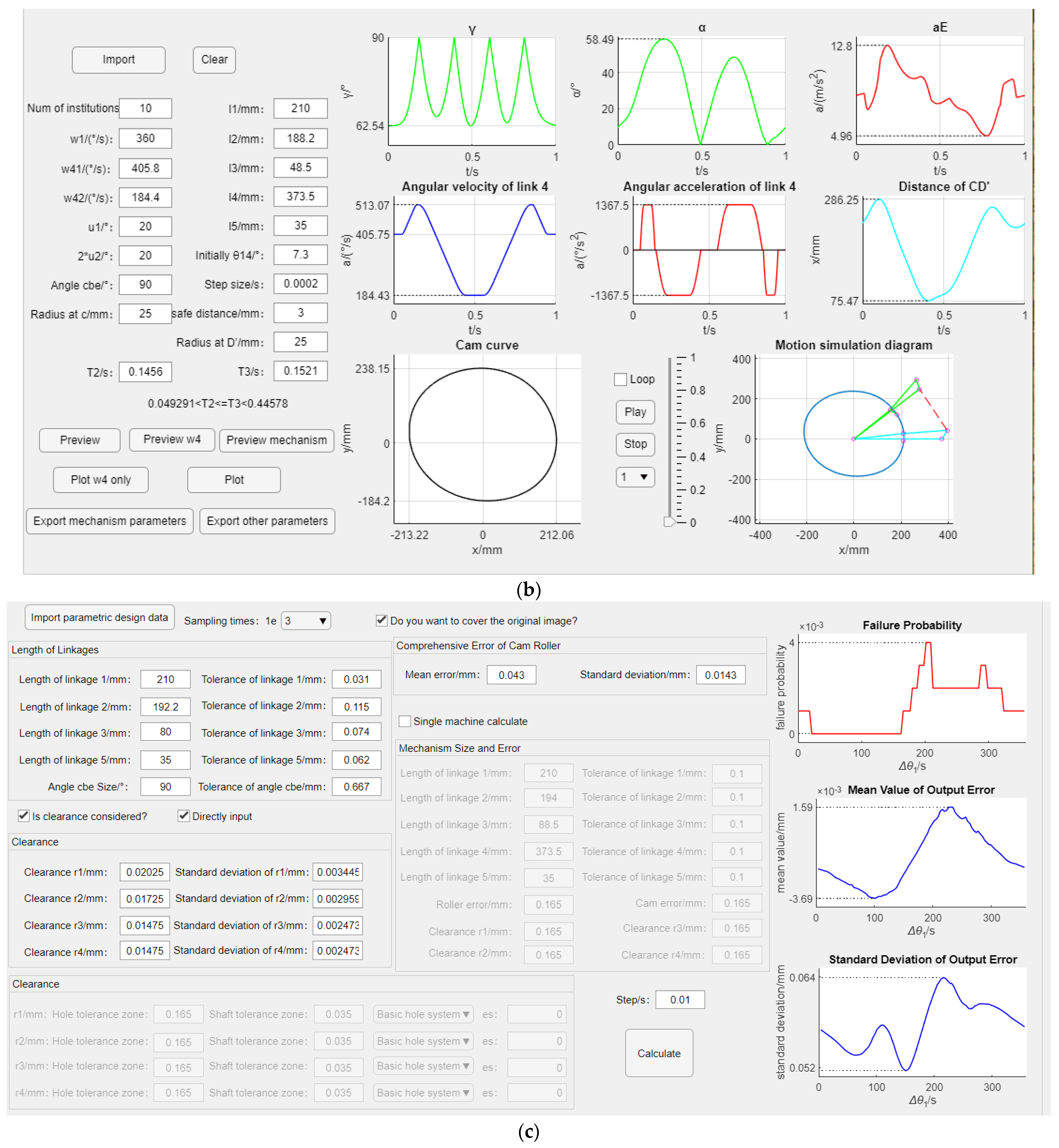
(3) A computer-aided platform is developed for the design analysis of the cam five-bar mechanism. The parameter calculation, optimization, and reliability analysis are well-handled with the aid of the software package.
(4) A real-world case study of the transverse device is put forward to demonstrate the effectiveness of the proposed method. The productivity of the transverse device is substantially improved.
The rest of this paper is structured as follows. Section 2 outlines the modeling analysis of the cam five-bar mechanism. Section 3 proposes the multi-objective optimization method. Section 4 presents the reliability analysis of kinematic accuracy. Section 5 provides the model validation and discussion. Finally, the paper is concluded in Section 6.

2. Cam Five-Bar Mechanism

2.1. Mechanism Principle

Compared with traditional cam-linkage mechanisms, the compactness of the large-size cam-linkage mechanism is poor. The fatigue damage and wear also differ significantly. In this study, we take the cam five-bar mechanism as an example to investigate the design optimization of the large-size cam-linkage mechanism, which is shown in Figure 1.
In general, the objective of the cam five-bar mechanism is to achieve a controlled change of the rotational angular speed with the rotation angle. As illustrated in Figure 1, the cam five-bar mechanism is composed of one cam and five bars. Rod 1 is the prime mover, whose angular velocity is constant. Rod 4 is the output member, whose angular velocity is supposed to meet working requirements. In addition, rods 2 and 5 are fixedly connected. Rods 2 and 3 generate the triangle BCD. During the system operation, the angle BCD would be changed if the motion state of rod 2 is adjusted through the cam. Correspondingly, the distance between B and D is also changed. As a result, the movement of the output member (i.e., rod 4) can be determined by adjusting the distance between B and D.
Theoretically, the output angular velocity and cam shape can be uniquely determined if the angular velocity of rod 1 and the length of each rod are known. This process of deriving the output velocity and cam shape from the given input angular velocity and rod structure is known as a positive solution. By contrast, the input and output angular velocities are often given in real applications, whereas the linkage mechanism characteristics and cam shape need to be resolved. This process is known as inverse solving. Compared with the positive solution, reverse solving may produce multiple solutions in which the motion characteristics of different structures can vary significantly. For example, some cam shapes may generate certain points where the pressure angle is too large, resulting in uneven motion and poor forces. Similarly, some linkage structures may produce points where the transmission angle is too small or even dead in motion. Thus, it is quite challenging to identify excellent motion characteristics while performing inverse solving.

2.2. Mathematical Model

As shown in Figure 1, a right-angle coordinate system Oxy is established to facilitate the theoretical analysis. The center of rotation of the prime mover (point A) is set as the origin (i.e., O). Suppose l1, l2, l3, l4, and l5 are the lengths of the corresponding rods. ω1 is the angular velocity of the prime mover. θ1 is the angle of rotation. ω4 and θ4 are the angular velocity and angle of rotation to be satisfied by the follower, respectively. The vector equation is obtained as:
l 1 + l 2 = l 3 + l 4
where l1, l2, l3, and l4 are vectors of magnitude l1, l2, l3, and l4, respectively.
By expressing Equation (1) in complex form and expanding it according to Euler’s formula, it can be written as:
[ c o s θ 1 c o s θ 2 s i n θ 1 s i n θ 2 ] [ l 1 l 2 ] = [ c o s θ 3 c o s θ 4 s i n θ 3 s i n θ 4 ] [ l 3 l 4 ]
Then, the rotation angle of each rod is obtained as:
θ 3 = 2 a r c t a n B 1 ± D 1 A 1 C 1 + θ 4
θ 2 = a r c t a n B 1 + l 3 sin ( θ 3 θ 4 ) A 1 + l 3 cos ( θ 3 θ 4 ) + θ 4
θ 5 = 360 + θ 2 ψ
where A 1 = l 4 l 1 c o s ( θ 1 θ 4 ) , B 1 = l 1 s i n ( θ 1 θ 4 ) , C 1 = ( A 1 2 + B 1 2 + l 3 2 l 2 2 ) / ( 2 l 3 ) , and D 1 = A 1 2 + B 1 2 C 1 2 .
To find the final solution, i.e., the trajectories of points A, B, C, D, and E, the values of l1, l2, l3, l4, l5, Ψ, ω4, and ω1 and the initial value of θ14 (the angle between rod 1 and rod 4) need to be determined. In real practice, ω4 is usually given as ω41 and ω42, which is shown in Figure 2. The connection curve between ω41 and ω42 can have many choices. The angular velocity ω4 is completely determined only after selecting the connection curve concerning the actual working condition requirement.
Thus, the coordinates of each point in the motion of the cam five-bar mechanism are determined as:
x b y b x c y c x d y d x e y e = cos θ 1 0 0 0 sin θ 1 0 0 0 cos θ 1 cos θ 2 0 0 sin θ 1 sin θ 2 0 0 0 0 cos θ 4 0 0 0 sin θ 4 0 cos θ 1 0 0 cos θ 5 sin θ 1 0 0 sin θ 5 l 1 l 2 l 3 l 4
where xi and yi (i = b,c,d,e) are the horizontal and vertical coordinates of points B, C, D, and E, respectively.
By solving Equation (6), the following mechanism motion characteristics can be obtained.
(1) Cam theoretical profile curve:
From the above analysis, it can be concluded that the trajectory of point E is the theoretical contour curve of the cam.
(2) Acceleration at point E during the motion of the mechanism:
a e = ( x e ) 2 + ( y e ) 2
where xe″ and ye″ are the horizontal and vertical accelerations of point E, respectively. ae is the acceleration at point E.
(3) Transmission angle:
γ = { φ 1 ,     φ 1 90 ° 180 φ 1 ,     φ 1 > 90 °
where φ1 is the angle between rods 2 and 3.
(4) Cam pressure angle:
α = { | β 1 β 2 | ,     | β 1 β 2 | 90 ° 180 | β 1 β 2 | ,     | β 1 β 2 | > 90 °
where β 1 = a r c t a n y e y d x e x d and β 2 = a r c t a n d y e d x e .

3. Multi-Objective Optimization Method

After determining the motion characteristics and the cam profile curve, a particle swarm-based multi-objective optimization method is proposed to determine the optimal solution for the inverse solving, which is conducted as follows.

3.1. Selection of Optimization Variables

In light of the mathematical analysis of the cam five-bar mechanism, the initial values of θ14, ω4, and rod lengths l1, l2, l3, and l5 are selected as optimization variables to enhance the motion characteristics of the mechanism.
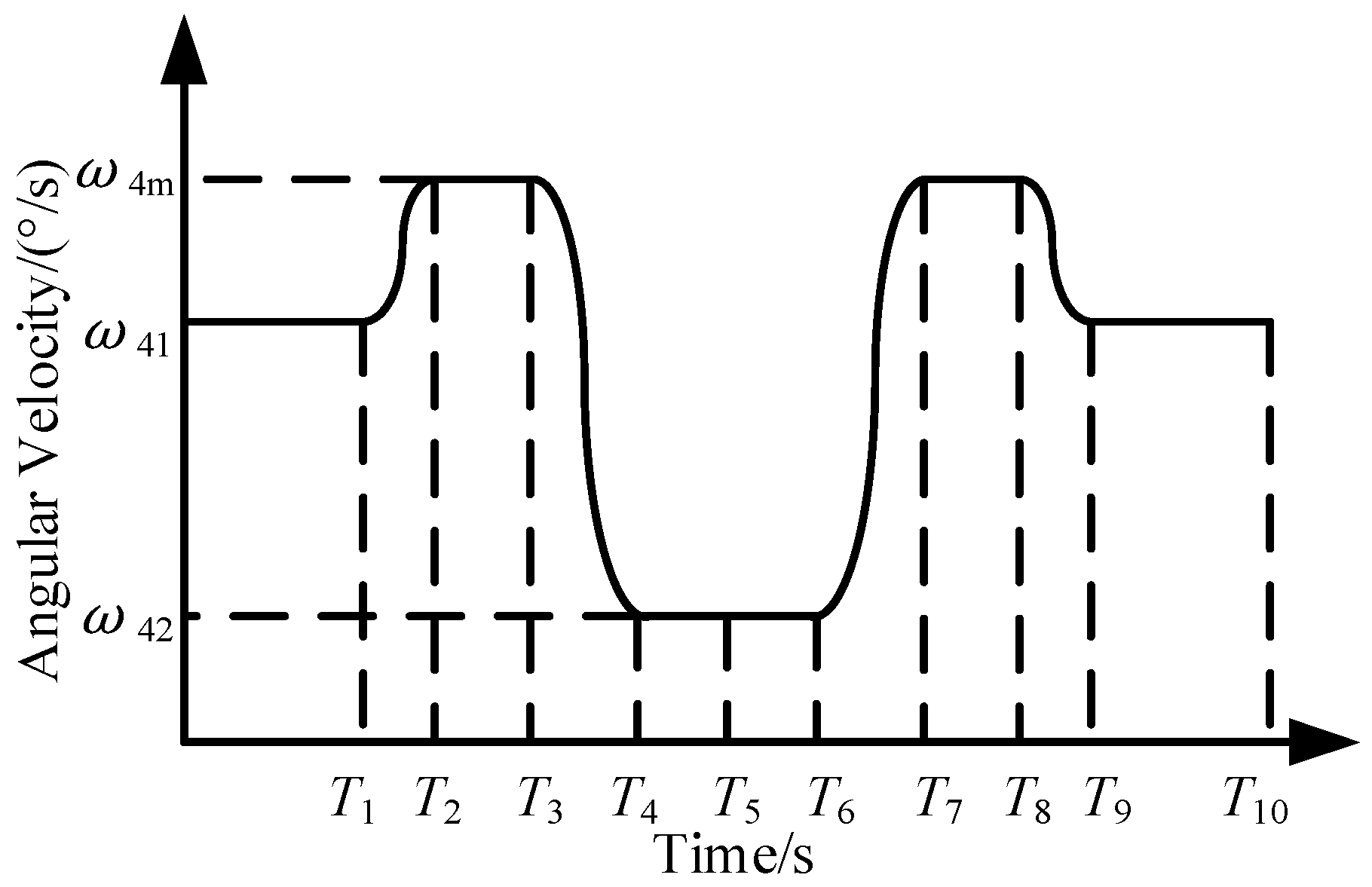
First of all, a combination of five straight lines and four curves is introduced for the representation of ω4, which is depicted in Figure 3. Specifically, the angular velocity of the 0~T1, T4~T6, and T9~T10 periods are given in advance. Therefore, the remaining curve is divided into two parts. The first part is the T2~T3 and T7~T8 periods, while the second is the period of T1~T2, T3~T4, T6~T7, and T8~T9. In particular, the angular velocity keeps constant in the first part, whereas the second part (i.e., the buffer section) introduces a motion law curve as the corresponding angular velocity curve. The integration of ω4 in the 0 to T10 period is 360°.
As illustrated in Figure 3, the first part of the curve can be considered symmetric about t = T5. Then, the time parameters are determined as:
T 1 T 4 T 6 T 7 T 8 T 9 = 1 ω 41 0 0 0 0 1 ω 42 0 0 0 1 ω 42 0 0 0 1 ω 42 0 1 0 0 1 0 1 ω 41 0 0 0 μ 1 μ 2 T 2 T 3 + 0 180 ω 41 180 ω 1 180 ω 1 360 ω 1 360 ω 1
In addition, the curve of the buffer section is chosen as a centrosymmetric curve to simplify the calculation. The rotation angle of the output member 4 can be determined by Equation (11).
ω 41 T 2 + 1 2 ( ω 4 m ω 41 ) ( T 2 T 1 ) + ω 4 m ( T 3 T 2 ) + 1 2 ( ω 4 m ω 42 ) ( T 4 T 3 ) + ω 42 ( T 5 T 3 ) = 180 °
By solving Equation (11), ω4m is obtained as:
ω 4 m = 360 ω 41 ( T 1 + T 2 ) + ω 42 ( T 3 + T 4 2 T 5 ) T 3 + T 4 T 2 T 1
For the second part of the curve, the commonly-used follower motion law curves are modified sine, modified iso-velocity, and quintuple polynomials [21]. As the first-order derivative of the dwell-free modified iso-velocity curve is too small, the dwell-free revised iso-velocity curves are used for the buffer section.
In sum, the curve of ω4 can be linearly represented by T2 and T3. Therefore, the final optimization variable x can be determined as x = (l1, l2, l3, l5, θ14, T2, T3)T.

3.2. Constraint Establishment

When rods 2 and 3 are in a straight line, the mechanism is in the limit state. At this time, the angle between rods 1 and 4 is expressed as θmax. The following constraint should be satisfied:
l 1 2 + l 4 2 2 l 1 l 4 c o s θ m a x l 2 + l 3
T 2 T 3 < 0
Moreover, the following constraint should be satisfied for the large-size cam-linkage mechanism:
{ 100 l 1 400 150 l 2 + l 3 400 0 ° θ 14 i 10 °
where θ14i is the initial value of the angle between rods 1 and 4.

3.3. Model for the Optimal Design

Based on the above analysis, the objective of the optimization is to maximize the transmission angle of the five-bar mechanism, minimize the cam pressure angle, and minimize the acceleration at point E, which is represented as:
min [ a E m a x , α m a x , γ m i n ]
Then, the optimization model is obtained as:
min [ a E m a x , α m a x , γ m i n ] s . t .   l a 2 + l d 2 2 l a l d cos θ max l b + l c T 3 T 2 0 100 l 1 400 150 l 2 + l 3 400 0 ° θ 14 i 10 °
Finally, the particle swarm optimization (PSO) algorithm is introduced to resolve the optimization problem, which is described as:
v i k + 1 = w v i k + c 1 r a n d 1 ( p i k x i k ) + c 2 r a n d 2 ( p g k x i k )
x i k + 1 = x i k + v i k + 1
where w is the inertia weight, c 1 and c 2 are positive constants, and r a n d 1 and r a n d 2 are two random numbers in the [0, 1] interval. x i k and v i k are the current position and velocity of particle i , respectively. p i k is the optimal position of particle i. p g k is the best position among all the particles in the population. x i k + 1 and v i k + 1 are the updated position and velocity of particle i , respectively.
As a population-based optimization method, the optimal solution can be determined by updating the position and velocity of the particles. Once the optimization model is constructed, the solving process can be handled by the POS module in MATLAB.

4. Reliability Analysis of Kinematic Accuracy

In the process of reliability analysis, the mathematical model is generally established according to the reliability design principle and practical problems. Finally, a suitable algorithm is used to solve the problem. The general solution process is shown in Figure 4.

4.1. Mathematical Model of Reliability Analysis

Compared with the traditional cam-linkage mechanism, the geometric shape error of the cam five-bar mechanism with a large size has a more significant impact on motion accuracy, especially in the high-speed scenario. To investigate the kinematic accuracy of the optimized structure, a reliability analysis of motion accuracy is presented based on the Monte Carlo methodology.
Firstly, motion analysis is conducted before the reliability analysis. Specifically, the errors in the machining process of the rod are investigated in the motion analysis. Assuming l1′, l2′, l3′, l4′, and l5′ are the actual lengths of the corresponding rod shown in Figure 1, the intersection point with the theoretical contour line of the cam is E′(xE′, yE′). Then, the vector equation of the linkage mechanism considering the errors is built as:
{ l 1 + l 2 = l 3 + l 4 l 1 + l 5 = l A E
By the transformation operation similar to Equation (1), Equation (20) is also written as:
[ c o s θ 1 c o s θ 2 c o s θ 3 c o s θ 4 s i n θ 1 s i n θ 2 s i n θ 3 s i n θ 4 ] [ l 1 l 2 l 3 l 4 ] = [ 0 0 ]
[ c o s θ 1 c o s θ 5 s i n θ 1 s i n θ 5 ] [ l 1 l 5 ] = [ x E x E ]
Accordingly, θ3 and θ4 are obtained as:
θ 3 = 2 a r c t a n [ B 0 ± B 0 2 + A 0 2 C 0 2 A 0 C 0 ]
θ 4 = a r c t a n l 3 s i n θ 3 + P 0 R 0 l 3 c o s θ 3 + O 0 Q 0
where A 0 = 2 l 3 ( O 0 Q 0 ) , B 0 = 2 l 3 ( P 0 R 0 ) , C 0 = l 3 2 + ( O 0 Q 0 ) 2 + ( P 0 R 0 ) 2 l 4 2 , and
[ O 0 P 0 Q 0 R 0 ] = [ c o s θ 1 0 s i n θ 1 0 0 c o s θ 2 0 s i n θ 2 ] [ l 1 l 2 ] .
In addition to the linkage mechanism, the cam and the roller errors are also investigated. As shown in Figure 5, Δl is the cam’s shape error. rg is the roller radius error.
Ideally, the cam and the roller are in tangential contact at point C. However, the point would change from C to C′, when Δl and rg are taken into account. Then, the angular error Δθ5 of rod 5 is calculated as:
Δ θ 5 = δ l 5 cos ( 1 θ 5 )
where δ indicates the combined error of roller radius and cam geometry, δ = Δl + rg.
The rotational angle θ5 of rod 5 is obtained as:
θ 5 = a r c t a n l 1 s i n θ 1 y E l 1 c o s θ 1 y E + δ l 5 c o s ( α θ 5 )
Therefore, the actual output angle of the mechanism at any given moment can be obtained from the above motion analysis. In addition, the dimensional errors of the components can be considered mutually independent and normally distributed random variables [13]. The probability distribution function N(μ,σ) of each rod size can be obtained according to the “3σ principle”.

4.2. Reliability Analysis

After the mathematical model is established, the Monte Carlo strategy is introduced to conduct the reliability analysis, which is illustrated in Figure 6.
In Figure 6, I(X) indicates the number of samples that meet the requirements. g(X) is the limit state function, by which the product is judged to be failing or not.
In the process of reliability analysis by Monte Carlo strategy, first set the sampling number, input the probability distribution function of the variables to generate N samples, and then substitute each sample into the limit state function for calculation. The Monte Carlo method is a numerical calculation technique guided by probabilistic statistical theory. It estimates the overall probability of failure by the failure frequency of the sample, which is described as:
P ^ f = N F N
where P ^ f is the probability of failure estimate. NF indicates the number of g ( X j ) F , where F is the failure domain.
In Equation (27), the number of samples N should be chosen with a balance of computational speed and accuracy. The appropriate number of samples is determined based on the failure probability of the mechanism. Thus, the calculated failure probability will not be seriously distorted and large errors can be avoided.
Based on the probability of failure, the evaluation parameters (e.g., the mean value of errors) can be calculated.

4.3. Software Development

In addition to the theoretical analysis, this paper proposes a computer-aided design platform to assist the design analysis of the cam five-bar mechanism, which is developed based on MATLAB. As depicted in Figure 7, the software package is composed of three modules: optimization, parameter calculation, and reliability analysis.

5. Model Validation and Discussion

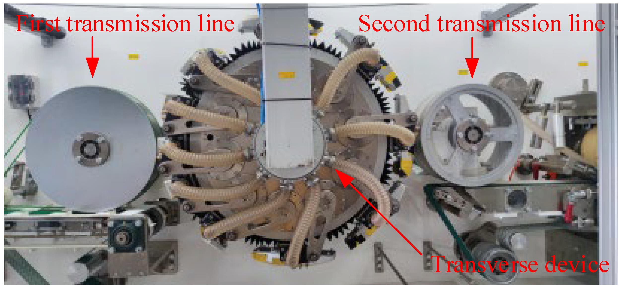
To demonstrate the effectiveness of the proposed method, a real-world case study of the design analysis for a transverse device is presented in this section. As illustrated in Figure 8, the transverse device is core equipment in a sanitary product production line. It is mainly used to shift the product from a horizontal to a vertical placement.
Corresponding to the physical structure, the working diagram of the production line is shown in Figure 9. Initially, the products are placed horizontally on the first conveyor, moving with speed v1. x1 is the spacing between products on the first conveyor. During the system operation, the intermediate mechanism (i.e., the transverse device, width: d) would pass the products from the first conveyor to the second conveyor, with the placement changing from horizontal to vertical. Accordingly, the spacing and moving speed are changed to x2 and v2, respectively.
According to the working requirement of the production line, a cam five-bar mechanism is developed for the transverse device. As shown in Figure 10, the cam five-bar mechanism consists of a linkage mechanism 1-2-3-4 and a cam mechanism 5-6, where member 1 is a rotating disc, member 2 is a rocker arm, and member 3 is a linkage. Output member 4 is composed of a wind box assembly and a circular guideway.
During the system operation, the cam is fixed. Rotating disc 1 acts as the prime mover to rotate the whole mechanism. Rocker arm 2 is connected to the cam. As the cam constrains one free degree of the structure, the system can be considered a cam five-bar mechanism.

5.1. Original Mechanism Motion Characteristics

Figure 11 shows the principle illustration of the cam five-bar mechanism used in the transverse device. The values of l1, l2, l3, l4, and l5 are 210 mm, 176 mm, 58.5 mm, 373.5 mm, and 35 mm, respectively. ω1 = 360°/s, Ψ = 90°, and the initial value of θ14 is 2°.
According to the working requirements, the ω41 and ω42 are determined as 405.75°/s and 184.43°/s, respectively. A dwell-free modified iso-velocity curve [21] is adopted in the buffer section. Then, the motion law of the output member is obtained, as shown in Figure 12.
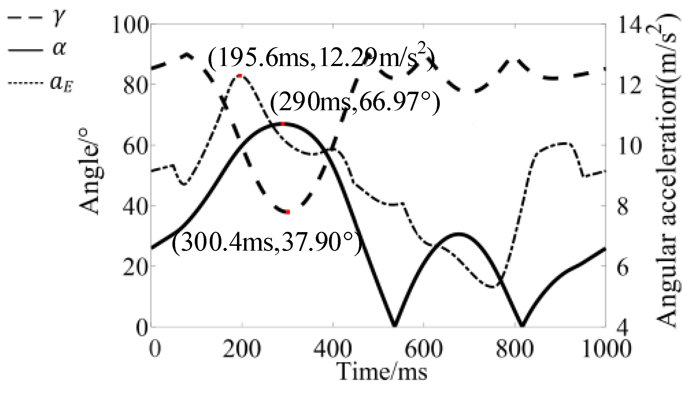
Finally, the motion characteristics of the mechanism and the cam theory curve are determined by resolving the model for the forward solution, which are shown in Figure 13 and Figure 14 respectively. In Figure 13, γmin is 37.90°, αmax is 66.97° and aEmax is 12.29 m/s2.

5.2. Optimization Results Analysis

In line with the multi-objective optimization method proposed in Section 3, the optimal solution is obtained as l1 = 210 mm, l2 = 192.2 mm, l3 = 80 mm, l5 = 35 mm, θ14 = 15.38°, T2 = 0.0943 s, and T3 = 0.2534 s. Correspondingly, the optimized motion characteristics and cam theory curve are depicted in Figure 15 and Figure 16, respectively.
In Figure 15, γmin is 74.61°, αmax is 46.29° and aEmax is 11.48 m/s2. Compared with Figure 13, the relevant performance parameters are optimized. The new motion characteristics meet the design requirements (i.e., γmin ≥ 40° and αmax ≤ 50°).
As well as the motion characteristics, the angular velocity ω4 and angular acceleration a4 curves are obtained, which are shown in Figure 17. Compared with the ω4 curve before optimization (Figure 12), the angular acceleration of the output member becomes smaller.

5.3. Reliability Analysis of Kinematic Accuracy

Corresponding to the framework proposed in Section 4, the reliability analysis of kinematic accuracy is conducted for the optimized mechanism. The parameters of each rod are listed in Table 1.
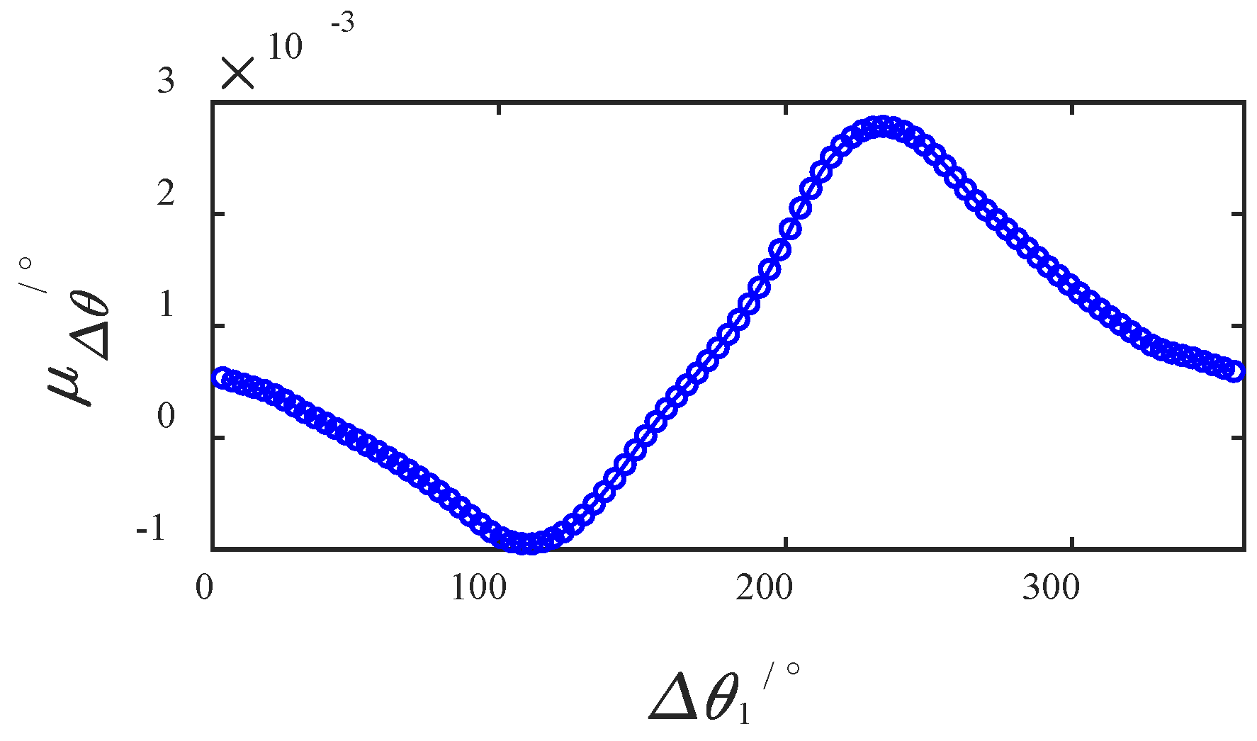
Based on the above reliability analysis model, the average value of component size error is shown in Figure 18.
From Figure 18, it can be concluded that the absolute value of the average angle error of rod 4 is less than 0.003° in a movement cycle. It meets the production requirements.

5.4. Comparison of Structure and Motion Characteristics

Table 2 and Table 3 present the specific parameters before and after optimization. The comparison shows that the maximum acceleration at point E is slightly reduced after optimization. The transmission angle and pressure angle are optimized significantly, with the minimum value of the transmission angle increased by 96.8% and the maximum value of the pressure angle reduced by 30.9%. The new motion characteristics meet the design requirements (i.e., γmin ≥ 40° and αmax ≤ 50°).
Figure 19 illustrates the comparison of the cam curves before and after optimization. As shown in Figure 19, the optimized cam profile size is smaller. It improves the compactness of the overall mechanism and ensures excellent motion characteristics.

5.5. Engineering Applications

In light of the optimized rod parameters and cam curve, the transverse device is redesigned, which is shown in Figure 20. 
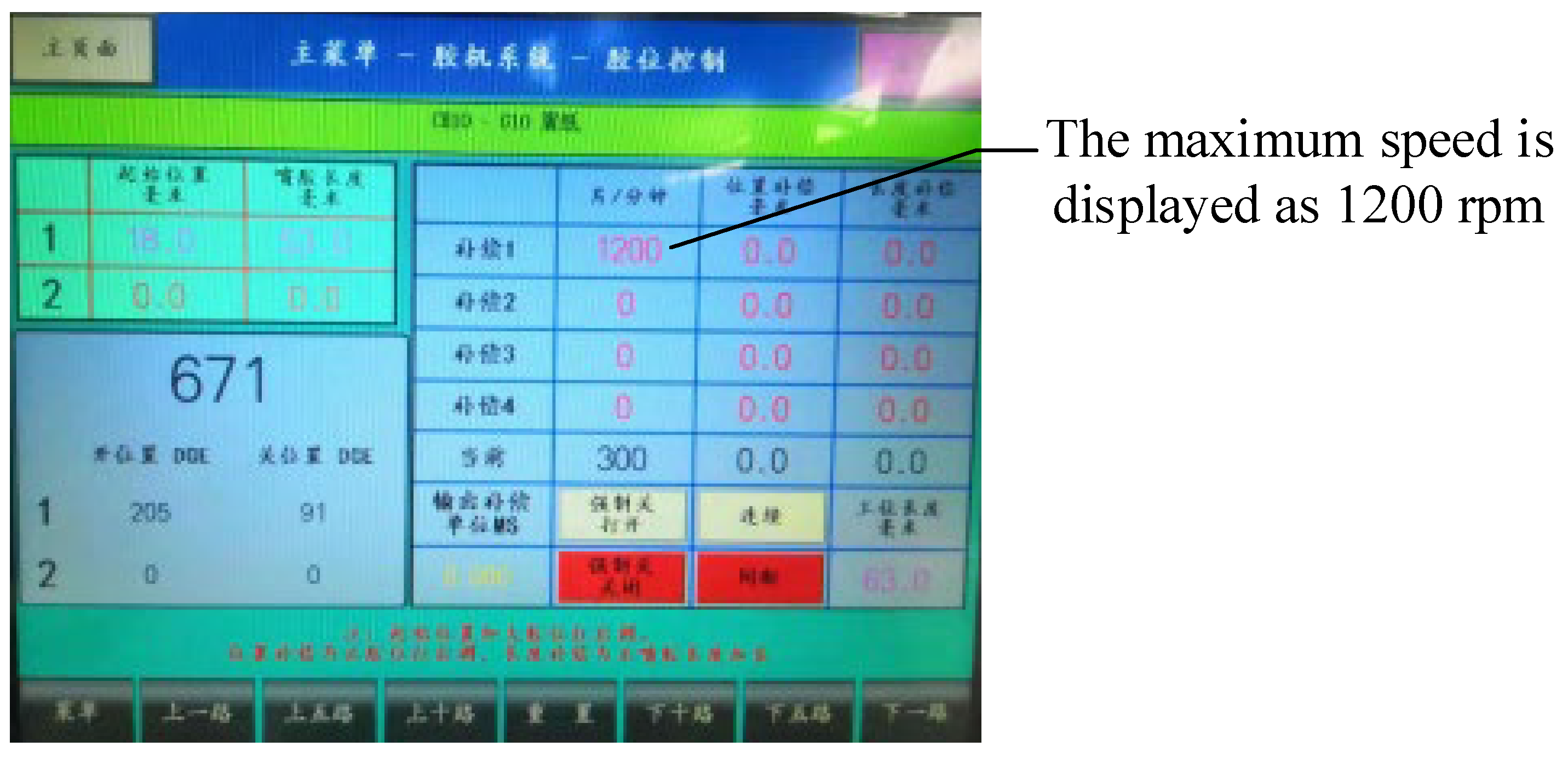
Figure 21 illustrates the working state of the new transverse device.
As depicted in Figure 21, the optimized transverse device can reach a maximum speed of 1200 pieces per minute (PPM). Compared with the original productivity of 600 PPM, the productivity is significantly improved.

6. Conclusions

To investigate the motion characteristics and kinematic accuracy of the cam-linkage mechanism under high-speed scenarios, this paper proposes a series of methods for the kinematic modeling, optimization, and reliability analysis of the large-size cam-linkage mechanism considering kinematic performance. The conclusions are as follows.
(1) A mathematical model is constructed to determine the performance parameters of the cam-linkage mechanism, such as E-point acceleration, transmission angle, and cam pressure angle.
(2) A multi-objective optimization methodology is proposed for the parameter optimization of the large-size cam-linkage mechanism. The co-linear of rods 2 and 3 is set as constraint, while the maximum drive angle, minimum cam pressure angle, and minimum E-point acceleration are taken as the objective function.
(3) The kinematic model of the cam-linkage mechanism is presented. Reliability analysis is conducted to evaluate the kinematic accuracy of the optimized mechanisms.
(4) A computer-aided platform is developed to assist the parameter calculation, optimization, and reliability analysis of the cam-linkage mechanism.
(5) The effectiveness of the proposed method is validated by a real-world case study. The productivity of the transverse device is increased from 600 PPM to 1200 PPM.

Author Contributions

G.Z.: conceptualization, data collection, data analysis, visualization, computer-aided design, computer-aided manufacturing, software, and original draft writing; Y.W.: conceptualization, data analysis, project administration, computer-aided manufacturing, supervision, and manuscript review and editing; G.-N.Z.: conceptualization, investigation, supervision, and manuscript review and editing; M.W.: data analysis, visualization, software, and manuscript review and editing; J.L.: data collection and visualization; J.Z.: data collection, data analysis, software and computer-aided design; B.L.: data collection and visualization. All authors have read and agreed to the published version of the manuscript.

Funding

This work is supported by the Department of Science and Technology of Anhui Province, China, under the Foundation of Anhui Province Science and Technology Major Project (grant number: 202003a0502041).

Data Availability Statement

All data generated during this work are available in the manuscript.

Conflicts of Interest

The authors declare no conflict of interest.

References

  1. Yu, H.; Yin, H.; Peng, J.; Wang, L. Quasi static analysis of heald frame driven by rotary Dobby with cam-linkage modulator. J. Text. Eng. 2020, 66, 37–45. [Google Scholar] [CrossRef]
  2. Li, M.; Zhang, X.H.; Yan, J.Q. Mathematical modeling and optimization of transverse heat sealing and cutting mechanism. J. Chin. Inst. Eng. 2022, 45, 385–390. [Google Scholar] [CrossRef]
  3. Zhao, P.; Zhu, L.; Zi, B.; Li, X. Design of Planar 1-DOF cam-linkages for lower-limb rehabilitation via kinematic-mapping motion synthesis framework. J. Mech. Robot. 2019, 11, 041006. [Google Scholar] [CrossRef]
  4. Liu, Y.; Zhang, J.; Wang, L.; Li, L.; Shi, Y.; Xie, G.; Wang, X. Optimization design of a bionic horse’s leg system driven by a cam-linkage mechanism. Proc. Inst. Mech. Eng. Part C J. Mech. Eng. Sci. 2022. [Google Scholar] [CrossRef]
  5. Wen, H.; Cong, M.; Xu, W.; Zhang, Z.; Dai, M. Optimal design of a linkage-cam mechanism-based redundantly actuated parallel manipulator. Front. Mech. Eng. 2021, 16, 451–467. [Google Scholar] [CrossRef]
  6. Rybansky, D.; Sotola, M.; Marsalek, P.; Poruba, Z.; Fusek, M. Study of Optimal Cam Design of Dual-Axle Spring-Loaded Camming Device. Materials 2021, 14, 1940. [Google Scholar] [CrossRef] [PubMed]
  7. Abderazek, H.; Yildiz, A.R.; Mirjalili, S. Comparison of recent optimization algorithms for design optimization of a cam-follower mechanism. Knowl.-Based Syst. 2020, 191, 105237. [Google Scholar] [CrossRef]
  8. Li, G.; Long, X.; Zhou, M. A new design method based on feature reusing of the non-standard cam structure for automotive panels stamping dies. J. Intell. Manuf. 2019, 30, 2085–2100. [Google Scholar] [CrossRef]
  9. Zhang, C.; Zhang, X.; Ye, H.; Wei, M.; Ning, X. An efficient parking solution: A cam-linkage double-parallelogram mechanism based 1-degrees of freedom stack parking system. J. Mech. Robot. 2019, 11, 045001. [Google Scholar] [CrossRef]
  10. Wu, X.; Wang, K.; Wang, Y.; Bai, S. Kinematic design and analysis of a 6-DOF spatial five-bar linkage. Mech. Mach. Theory 2021, 158, 104227. [Google Scholar] [CrossRef]
  11. Arabaci, E. Dimensionless design approach to translating flat faced follower mechanism with two-circular-arc cam. Mech. Sci. 2019, 10, 497–503. [Google Scholar] [CrossRef] [Green Version]
  12. Xia, B.Z.; Liu, X.C.; Shang, X.; Ren, S.Y. Improving cam profile design optimization based on classical splines and dynamic model. J. Cent. South Univ. 2017, 24, 1817–1825. [Google Scholar] [CrossRef]
  13. Ouyang, T.; Wang, P.; Huang, H.; Zhang, N.; Chen, N. Mathematical modeling and optimization of cam mechanism in delivery system of an offset press. Mech. Mach. Theory 2017, 110, 100–114. [Google Scholar] [CrossRef]
  14. Chen, T.H. The systematic design and prototype verification of cam-linkage polishing devices with double-circle polishing traces. Adv. Mech. Eng. 2018, 10, 1687814018818974. [Google Scholar] [CrossRef]
  15. Chang, W.T.; Hu, Y.E. An integrally formed design for the rotational balancing of disk cams. Mech. Mach. Theory 2021, 161, 104282. [Google Scholar] [CrossRef]
  16. Li, M.; Yan, J.; Zhao, H.; Ma, G.; Li, Y. Mechanically Assisted Neurorehabilitation: A Novel Six-Bar Linkage Mechanism for Gait Rehabilitation. IEEE Trans. Neural Syst. Rehabil. Eng. 2021, 29, 985–992. [Google Scholar] [CrossRef] [PubMed]
  17. Yang, Y.; Xie, R.; Wang, J.; Tao, S. Design of a novel coaxial cam-linkage indexing mechanism. Mech. Mach. Theory 2022, 169, 104681. [Google Scholar] [CrossRef]
  18. Yang, Y.; Wang, J.; Zhou, S.; Huang, T. Design of a novel coaxial eccentric indexing cam mechanism. Mech. Mach. Theory 2019, 132, 1–12. [Google Scholar] [CrossRef]
  19. Radaelli, G. Reverse-twisting of helicoidal shells to obtain neutrally stable linkage mechanisms. Int. J. Mech. Sci. 2021, 202, 106532. [Google Scholar] [CrossRef]
  20. Wang, X.; Wang, T.; He, X.; Ma, Z. Effect of Cam Angular Velocity on Working Efficiency of Fuel Engine. J. Phys. Conf. Ser. 2020, 1533, 042064. [Google Scholar]
  21. Li, J.; Zhao, H.; Zhang, L. Transmission and tooth profile equation of swing output movable teeth cam mechanism. J. Mech. Eng. 2018, 54, 23–31. (In Chinese) [Google Scholar] [CrossRef]
Figure 1. Schematic diagram of the cam five-bar mechanism.
Actuators 12 00002 g001
Figure 2. The desired motion law of the output member.
Actuators 12 00002 g002
Figure 3. Angular velocity curve of the output component.
Actuators 12 00002 g003
Figure 4. The general process of reliability analysis.
Actuators 12 00002 g004
Figure 5. Error diagram of the swing cam mechanism.
Actuators 12 00002 g005
Figure 6. Flow chart of Monte Carlo reliability analysis.
Actuators 12 00002 g006
Figure 7. Software interface. (a) Optimization module (b) Parameter calculation module (c) Reliability analysis module.
Actuators 12 00002 g007aActuators 12 00002 g007b
Figure 8. Physical diagram of the transverse device.
Actuators 12 00002 g008
Figure 9. Production line working diagram.
Actuators 12 00002 g009
Figure 10. Cam five-bar mechanism in the transverse device.
Actuators 12 00002 g010
Figure 11. Principle illustration of the cam five-bar mechanism.
Actuators 12 00002 g011
Figure 12. ω4 curve before optimization.
Actuators 12 00002 g012
Figure 13. Motion characteristics before optimization.
Actuators 12 00002 g013
Figure 14. Cam theory curve before optimization.
Actuators 12 00002 g014
Figure 15. Motion characteristics after optimization.
Actuators 12 00002 g015
Figure 16. Cam theory curve after optimization.
Actuators 12 00002 g016
Figure 17. ω4 curve after optimization.
Actuators 12 00002 g017
Figure 18. Mean value of rod 4 angle error.
Actuators 12 00002 g018
Figure 19. Comparison before and after cam optimization.
Actuators 12 00002 g019
Figure 20. Optimized transverse device (side).
Actuators 12 00002 g020
Figure 21. The maximum running speed of the transverse device.
Actuators 12 00002 g021
Table 1. Parameters related to each rod.
Parameter NameMean ValueToleranceStandard Deviation
l1/mm2100.030.0052
l2/mm192.20.120.0192
l3/mm800.070.0123
l4/mm350.060.0104
Ψ900.670.111
δ/mm0.0430.0143
Table 2. Comparison of motion characteristics parameters.
Parameter Nameαmax/(°)γmin/(°)aEmax (m/s2)
Before optimization66.9737.9012.90
After optimization46.2974.6111.48
Table 3. Comparison of connecting rod parameters.
Statusl1/mml2/mml3/mml5/mmInitially θ14/(°)
Before optimization21017658.5352
After optimization210192.2803515.38
Disclaimer/Publisher’s Note: The statements, opinions and data contained in all publications are solely those of the individual author(s) and contributor(s) and not of MDPI and/or the editor(s). MDPI and/or the editor(s) disclaim responsibility for any injury to people or property resulting from any ideas, methods, instructions or products referred to in the content.

