Review

Recent Developments on Dielectric Barrier Discharge (DBD) Plasma Actuators for Icing Mitigation

by
Frederico Rodrigues
1,*,
Mohammadmahdi Abdollahzadehsangroudi
1,
João Nunes-Pereira
1,2 and
José Páscoa
1
1
C-MAST, Centre for Mechanical and Aerospace Science and Technologies, Universidade da Beira Interior, Rua Marquês D’Ávila e Bolama, 6201-001 Covilhã, Portugal
2
CF-UM-UP, Centro de Física das Universidades do Minho e do Porto, Campus de Gualtar, 4710-057 Braga, Portugal
*
Author to whom correspondence should be addressed.
Actuators 2023, 12(1), 5; https://doi.org/10.3390/act12010005
Submission received: 9 November 2022 / Revised: 15 December 2022 / Accepted: 16 December 2022 / Published: 21 December 2022
(This article belongs to the Special Issue 10th Anniversary of Actuators)

Abstract

:
Ice accretion is a common issue on aircraft flying in cold climate conditions. The ice accumulation on aircraft surfaces disturbs the adjacent airflow field, increases the drag, and significantly reduces the aircraft’s aerodynamic performance. It also increases the weight of the aircraft and causes the failure of critical components in some situations, leading to premature aerodynamic stall and loss of control and lift. With this in mind, several authors have begun to study the thermal effects of plasma actuators for icing control and mitigation, considering both aeronautical and wind energy applications. Although this is a recent topic, several studies have already been performed, and it is clear this topic has attracted the attention of several research groups. Considering the importance and potential of using dielectric barrier discharge (DBD) plasma actuators for ice mitigation, we aim to present in this paper the first review on this topic, summarizing all the information reported in the literature about three major subtopics: thermal effects induced by DBD plasma actuators, plasma actuators’ ability in deicing and ice formation prevention, and ice detection capability of DBD plasma actuators. An overview of the characteristics of these devices is performed and conclusions are drawn regarding recent developments in the application of plasma actuators for icing mitigation purposes.

1. Introduction

Ice accretion on various component surfaces causes undesirable loads that pose a serious problem for aviation and wind turbines [1]. When aircraft fly in cold climates and pass through clouds containing supercooled water droplets, severe ice formation and subsequent icing on aircraft surfaces often occur [2,3]. This phenomenon of ice formation can negatively affect the normal operation of various aircraft components, for example, the aircraft wings. Ice accumulation on the leading edge of the aircraft wings disturbs the flow and degrades aerodynamic performance by increasing drag and reducing lift, which can seriously compromise flight safety [4,5]. It is estimated that 9% of aircraft safety accidents are originated by ice accretion [6].
Depending on the icing formation mechanism and conditions, different types of ice can form, usually defined as rime ice, glaze ice, or mixed ice. Rime ice occurs when droplets freeze almost immediately after impinging on the surface. This phenomenon usually occurs at low temperatures, low liquid water content, and low flow velocity [7]. On the other hand, glaze ice forms when the cooled water droplets freeze gradually after impinging on the surface. This phenomenon usually occurs at temperatures around 0 °C and with high liquid water content. Mixed ice, in turn, consists of a mixture of rime and glaze ice and occurs when both types of ice are formed [8,9]. Regardless of the type of ice, any ice accretion phenomenon can pose a hazard to the aircraft, but the formation of rime ice is usually less harmful to the aerodynamic performance of the wings [9]. The ice accretion on the surface, even in small amounts, increases the roughness of the surface and reduces maneuverability to a dangerous level [10]. In addition, ice can also build up in the aircraft’s speedometers and pressure sensors, making them difficult to operate [10]. Furthermore, ice crystals can form at high altitudes and coexist with the supercooled water droplets. If ice crystals are continuously ingested into the engine’s core compression system, they can provide sufficiently cold conditions to refreeze and accumulate on the engine surfaces, a phenomenon commonly referred to as “ice crystal icing”. This phenomenon can lead to loss of thrust, compressor damage, and/or flameout [11,12].
As in the aviation industry, ice accretion is also a major problem in the wind power industry [13]. Considering the limited wind power near the ground, the idea of operating wind turbines at high altitudes has grown in recent years, because wind speed increases significantly with altitude [14]. In the first thousand meters of altitude, the wind speed usually increases by about 0.1 m/s per 100 m of altitude, which is a considerable increase in wind energy, because the wind energy varies with the cube of wind speed [15]. In addition, cold regions are very attractive for wind energy generation [16]. In these regions, the higher air density at lower temperatures provides about 10% more available wind energy than in other regions [17]. Therefore, cold climate regions at high altitudes provide optimal conditions for wind energy generation, and, for this reason, about a quarter of the world’s wind turbine capacity is now installed in cold climate regions [18,19]. However, these regions also have favorable conditions for ice formation and accretion on wind turbines blades. The performance of wind turbines is affected by several factors, such as the blade design, the technical parameters of the turbine, the location, and the climate, in which blade icing is a critical factor that reduces the performance of the wind turbine [20]. It is estimated that the power loss of wind turbines due to icing can reach values up to 50% per year, depending also on the duration of icing [21]. In addition to the losses in electricity generation, the unbalanced loads caused by ice formation lead to deterioration of the components and shortening of their lifetime, which, in turn, significantly increases the maintenance costs of wind turbines [22]. Moreover, considering the possible use of small-scale vertical axis wind turbines in urban areas, ice accumulation increases the load and noise and can lead to ice shedding and ice throwing events that can generate dangerous projectiles [23].
Considering this background, and given the impact of ice accretion on the aviation and wind energy industries, several works have been carried out over the years to investigate and further develop different deicing systems [17,21]. One of the latest proposed deicing technologies is based on the use of surface dielectric barrier discharge (DBD) plasma actuators. These simple devices have been studied over the years for active flow control and aerodynamic efficiency improvement [24,25,26,27]. However, only recently have researchers started to investigate the possibility of using the thermal effects produced by these devices for deicing and anti-icing purposes [28,29]. Since these devices present a behavior similar to a capacitor, researchers have also investigated the possibility of using plasma actuators as capacitive ice sensors [30]. By combining all these functionalities, DBD plasma actuators can simultaneously detect ice formation and accumulation on the surface, perform deicing, and improve aerodynamic efficiency. Considering this enormous potential of DBD plasma actuators for anti-icing applications, the present work aims to review and critically exploit the recent developments in plasma actuators for icing mitigation applications. First, the traditional devices and techniques for deicing and ice sensing are discussed. Then, the design and operation of surface dielectric barrier discharge plasma actuators are explained, after which the ability of plasma actuators to induce thermal effects, perform deicing, and operate as ice sensors will be exploited in different subsections. To finalize the current work, several conclusions will be drawn about the potential of DBD plasma actuators for simultaneous deicing, ice sensing, and active flow control in aeronautics and wind turbine applications.

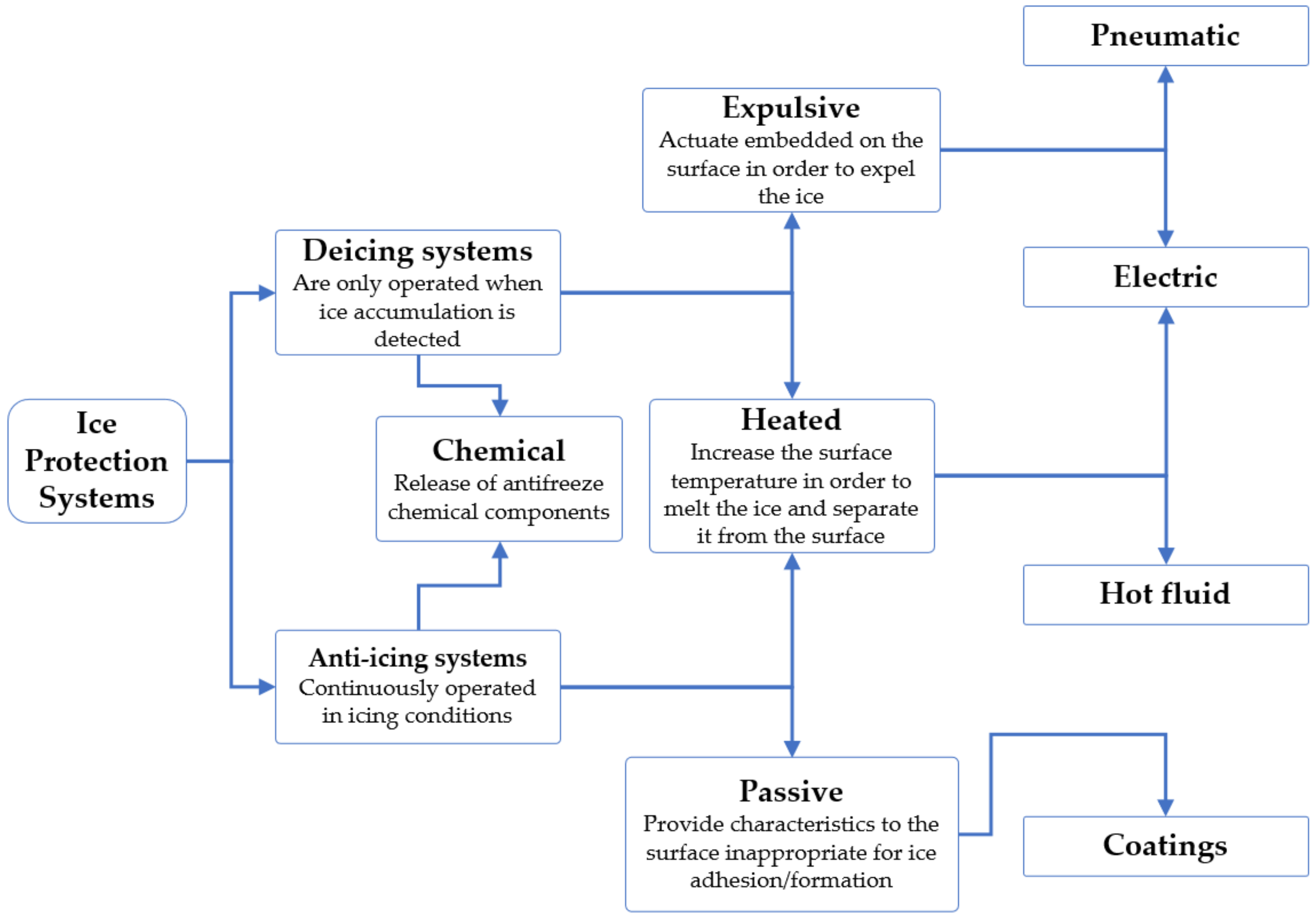
2. Traditional Techniques for Ice Protection Systems

Ice protection systems are designed to prevent ice accretion on wind turbine and aircraft surfaces (particularly leading edges) such as wings, propellers, rotor blades, engine intakes, and environmental control intakes. When the ice builds up to a significant thickness on the surfaces, it alters the shape of the airfoils and flight control surfaces, reduces wind turbine performance, and reduces the control or handling characteristics of the aircraft [31,32]. Ice protection systems can be based on deicing operations (removal of snow, ice, or frost from the surface), anti-icing operations (prevention of ice adhesion or delay of its formation or reformation), or combined deicing and anti-icing operations. Ice protection systems include the application of active and/or passive ice protection techniques. Active ice protection systems include the use of mechanical methods, the application of heat, the use of dry or liquid chemicals to lower the freezing point of water, or a combination of these various techniques. Passive ice protection systems, on the other hand, use coatings or modifications to surface structures to prevent or delay ice accretion on the surface. Figure 1 summarizes the different types of techniques used in ice protection systems that we will assess in the following subsections.

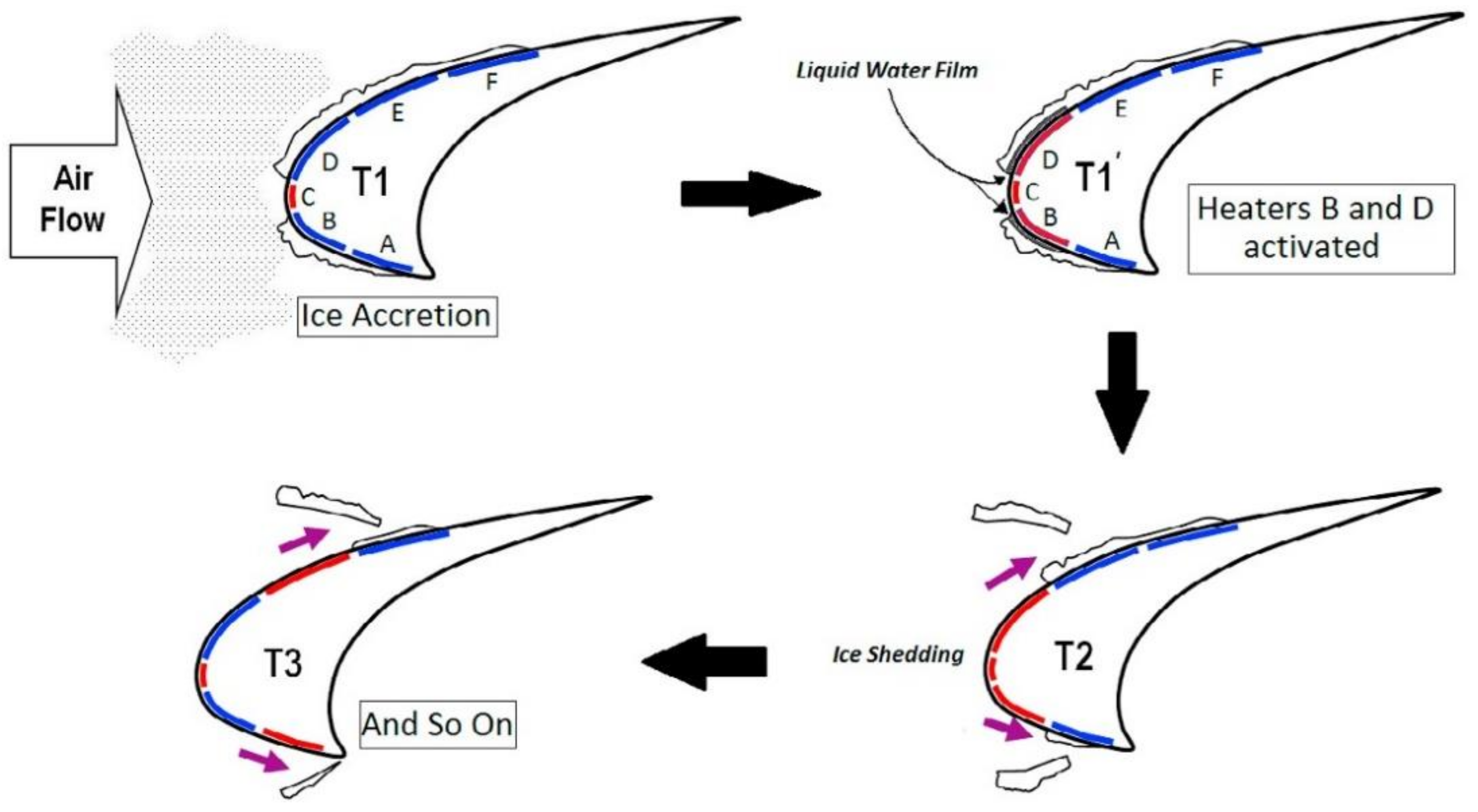
2.1. Traditional Deicing and Anti-Icing Techniques Used in Ice Protection Systems

The pneumatic deicing boot is a common mechanical technique for ice protection systems, generally used for in-flight deicing. This system consists of pneumatic boots generally installed on the leading edge of the wings and/or control surfaces, as ice accumulates particularly frequently in these areas. The pneumatic boot is commonly made of rubber layers with one or more air chambers between them so that they can be rapidly inflated and deflated to expel ice that has accumulated on the surface [33,34]. This rapid movement of the rubber breaks the adhesion of the ice, and it is removed and carried away by the airflow around the aircraft surface. This type of system is suitable for low and medium speed aircraft [17]. Ice protection systems based on pneumatic boots have the advantage of requiring low engine bleeding air, but the pneumatic boots need to be replaced frequently and also require frequent inspection and maintenance.
Another type of deicing system is based on the use of electrically resistive elements and is commonly referred to as an electro-thermal protection system [35,36,37,38]. A schematic illustrating the operation of an electro-thermal ice protection system is shown in Figure 2.
These elements generate heat when current is applied to them and are usually embedded in a rubber layer that is implemented in the leading edges of the surfaces that should be protected. These devices can operate continuously, providing a constant heat flux and preventing ice accretion, or intermittently, by removing ice only when it accretes. The second mode, in which the device operates as a deicer, involves much less power consumption because the system melts only the ice in contact with the surface to break the ice’s adhesion and shed it through the flow around the surface. Normally, when ice accumulation is detected, these systems first operate as a deicing system to melt and remove the ice that has already accumulated, and then operate as an anti-icing system to prevent continuous ice accumulation.
Electro-mechanical ice removal devices form another group of ice protection systems. Often referred to as EMEDS (Electro-Mechanical Expulsion Deicing Systems) [40,41,42], this type of system contains actuators installed on the surface of the structure that produce a mechanical force to expel the ice from the surface [43]. A schematic of this type of system is shown in Figure 3.
The system generally consists of an electronic deicing control unit (DCU) that controls the apparatus and operating times, an energy storage bank (ESB) that supplies high-current electrical pulses to the system, and a leading-edge assembly (LEA) that contains the actuators that are moved to induce a shock wave on the protected surface and expel the ice. The system uses microsecond-scale high-current electrical pulses delivered to the actuators to generate opposing electromagnetic fields. The electromagnetic fields cause the actuators to rapidly change shape, which causes the leading-edge surface to vibrate at a very high frequency, dislodging the accumulated ice. This system can also be combined with an electrical heating element which prevents ice accretion while the actuators remove the ice that has accumulated in the area downstream of the heated part. This hybrid system is generally called a Thermo-Mechanical Expulsion Deicing System (TMEDS) [44].
A recent method, still under development, is based on the application of ultrasonic vibrations to break and delaminate the ice accumulated on the surface that should be protected [45,46,47]. In this type of system, ultrasonic waves with high energy are used to generate a shear stress on the surface in contact with the ice layer, which can break and remove the ice [48]. This shear stress is generated by the difference in wave propagation speed between the ice and the surface due to the different physical properties of the two media. Compared to the electro-thermal deicing systems, the ultrasonic deicing systems are not thermal and, therefore, require much less energy. Some works have reported the potential of this type of ice protection systems. Palacios et al. [49] demonstrated that certain ultrasonic modes generated by horizontal shear waves produce sufficient shear stress to remove the accreted ice layer from a host structure, and Budinger et al. [50] reported on the resonance modes and ultrasonic frequencies for low-power ultrasonic deicers.
The deicing and ice removal operations can also be achieved using shape memory alloys. Shape memory alloys are used in this type of system because these materials can undergo a very large dimensional change induced by relatively small temperature variations. Considering this possible effect, the shape-changing properties of these materials are used in ice protection systems to promote ice removal [51,52,53].
Ice protection systems can also be based on very rapid electromagnetically induced vibrations. These systems are usually referred to as electro-expulsive systems and use an electric current passing through a parallel copper layer to create a repulsive magnetic field that induces small jumps of high acceleration on the upper conductor. This motion causes the ice to break into very small particles that are carried away by the adjacent airflow. This type of system is attractive for small aircraft, but it is not easy to install it on already existing wing structures [54,55]. On the other hand, there is also the electro impulse deicing system, which uses high-voltage capacitors that can be rapidly discharged by an electromagnetic coil, which in turn induces strong eddy currents in the metal surface that should be protected [56,57,58,59]. As a result, strong opposing electromagnetic forces are generated between the actuator coil and the metal surface, which is rapidly accelerated. This motion leads to the disruption of the ice and consequent shedding by the adjacent air stream [60]. The main disadvantage of this system is the electromagnetic interference and structural fatigue caused by its operation.
Another electrically operated ice protection system uses heating tapes made of thin graphite foil. This is a fast system that, when activated, instantaneously increases the temperature of the tape and melts the ice accreted on its surface, which is then carried away by the air flow. This system is very interesting because the thin graphite foil can be easily applied to the surface of various aircraft or wind turbine components. However, it has currently not been certified in aircraft flying under icing conditions [61,62].
The thermal air bleed anti-icing system is an additional ice protection system used primarily in modern larger jet aircraft and fixed wing transport aircraft [63,64]. In these systems, hot air is bled off the engine and transported by tubes in order to be exhausted through small holes in the lower surface of the wing. This hot air increases the surface temperature to a value above the freezing point of water in order to melt or evaporate the ice. In turbine-powered air vehicles, the hot air is usually extracted from the compressor section of the engine [65]. In contrast, for turbocharged and piston-powered aircraft, the bleed air is taken from the turbocharger. The work of Domingos et al. [66] is an example of a study that analyzed the implementation of a bleed air ice protection system. A few works have also reported the possible application of loop heat pipes (LHP) as an ice protection system. These loop heat pipes are highly efficient two-phase heat transfer systems that allow considerable amounts of heat to be transported over long distances. Studies have demonstrated their anti-icing ability and shown that they can be efficiently used as ice protection systems [67].
Another type of ice protection system is based on chemical deicing devices. In these systems, chemical antifreeze is pumped through small orifices on the surface to be protected to prevent ice accretion. Propylene glycol and ethylene glycol alcohol are examples of chemicals that can be used for this purpose. These components allow a protective layer to form on the surface of aircraft or wind turbine components that prevents the water from freezing at temperatures lower than the freezing point of water, thus delaying the possibility of ice formation and accumulation. However, the effectiveness of these systems in preventing ice formation is limited by the properties of the chemical and the prevailing weather conditions. In addition, under certain flow conditions, the rheology of the fluid may change and the thickness of the chemical layer may become too thin. In addition, the environmental impact of chemical deicing agents is still a major concern. Propylene glycol and ethylene glycol, although supposedly biodegradable, can pollute water resources, and they exert high levels of biochemical oxygen, which can adversely affect aquatic life. In addition, the system and liquid container are usually heavy and, thus, increase the weight of the aircraft [68,69,70].
All of the above-mentioned are systems that actively control ice formation and can be activated or deactivated. Another class of ice protection systems is the passive systems, which generally include techniques to modify the physicochemical properties of the surface to make it more difficult for ice to adhere to the surface [71]. The hydrophobic or superhydrophobic coatings represent a passive ice protection system. These coatings have a high degree of water resistance and a self-cleaning effect that can repel water, making it difficult or impossible for ice to form [72]. Another type of passive ice protection system is the use of surfaces with micro- and nanoscale rough structure. This type of surface usually reduces the time that the water remains in contact with the surface to a period that is less than the time it needs for the water droplet to come into contact with the frozen material to freeze and adhere [73]. The implementation of icephobic coatings is also a topic that has been investigated as a new type of ice protection system. Icephobic surfaces are different from hydrophobic or superhydrophobic surfaces and do not require any special treatment or chemicals, but instead use icephobic materials such as carbon nanotubes and slippery liquid infused porous surfaces. Huang et al. [39] performed a study on icephobic coatings and the possibility of using them in a hybrid coating and active ice mitigation system. These icephobic and hydrophobic coatings can also be combined with electro-thermal and auxiliary photo-thermal performances as passive ice protection systems [74,75]. The schematic shown in Figure 4 illustrates this possible combination. Solar anti-icing/deicing surfaces based on photothermal materials constitute a recent method for ice protection systems. This type of surface has grabbed the attention of several researchers that recently have focused their works on the development of photothermal materials which can be used for solar anti-icing/frosting surfaces (SASs) [76,77]. These surfaces can absorb sunlight efficiently and convert the absorbed solar light energy into thermal energy, which, in turn, can be used for delaying or preventing ice formation [78]. Since solar energy is pollution free and a renewable energy source available in most areas, the use of photothermal materials for solar icing mitigation surfaces is a sustainable and environmentally friendly approach [79]. In addition, this method is associated with superior surface adaptability, long-term durability, and low-cost, which makes it a promising and beneficial option for a wide range of anti-icing applications [80]. Carbon-based, plasmonic-metal-based, and semiconductor-based methods are some of the most relevant approaches reported in the literature for SASs. The most studied photothermal conversion materials include carbon materials, conjugated polymers, two-dimensional nano-structural materials, and metallic particles [78]. The main disadvantages of this technique include the fact that solar radiation is inherently intermittent and, due to weather changes, it might become hard to receive sunlight even during the daytime. In addition, most of the reported SASs cannot remove the condensed water effectively, which significantly enhances reflectance and leads to reduced photothermal efficiency and decreased temperature [78,79]. Considering this, it is highly important to understand the phase transitions of water molecules and the nucleation and growth process of crystals during the water solidification process, and solar interfacial evaporation can be considered in order to promote the water evaporation from the surface. For that purpose, solar interfacial evaporation methods can be used in order to photothermally concentrate the solar radiation absorbed by the surface, increase the surface temperature, and promote the vapor generation [81].
As we have seen up to now, the existent ice protection systems still present some issues. In addition, the existent ice protection techniques only present the functionality of deicing and/or anti-icing. This means that, when the weather changes and there are no favorable icing conditions, the ice protection system becomes useless and adds weight to the wind turbine blade. Therefore, in the current work, we focus on the use of DBD plasma actuators as ice protection devices. The main advantage of using DBD plasma actuators instead of the existent deicing technologies consists of the fact that they allow deicing and ice prevention accumulation to be performed when required, and when it is not necessary to perform deicing, the plasma actuator can be operated in active flow control mode, improving the wind turbine’s efficiency. In addition, we should emphasize that although there are some existing deicing technologies, such as superhydrophobic coatings or solar anti-icing/deicing surfaces, that do not lead to a significant weight increase, several other technologies, such as pneumatic deicing boots, electro-mechanical ice removal devices, or chemical deicing systems, are clearly associated with a considerable undesirable weight increase. Another advantage of plasma actuators is that they are very light, and the operation and control of plasma actuators can be achieved with circuit boards, including a full bridge converter and a transformer cascade board, that do not represent a considerable weight increase for the system.

2.2. Traditional Ice Sensors Used in Ice Protection Systems

Ice sensors can be integrated into anti/deicing systems to provide sufficient information to effectively operate ice mitigation devices [82]. In most aircraft ice detection systems, sensors cannot be placed directly on the airfoil surfaces that most need to be kept free. The addition of a protruding sensor would compromise the aerodynamics of the aircraft. While various attempts have been made to fabricate ice detectors, they have been limited by their accuracy, by their inability to distinguish between ice and water [83], and by their inability to measure the thickness of the ice.
Current existing ice detection methods can be divided into direct and indirect methods of ice detection [21]. Indirect methods use some weather conditions such as temperature, humidity, and visibility in conjunction with empirical deterministic models to predict icing events. These types of instruments are more expensive and not entirely reliable. Direct ice detection methods, on the other hand, measure the change in a property such as mass, conductivity, inductance, and dielectric constant to measure ice formation on the surface [84]. A direct ice detection method is based on ultrasonic damping [85]. The principle of this method is based on measuring the change in the transmission of sound waves. Some similar methods use piezoelectric sensors. This type of sensor detects the presence of ice by analyzing the wave packet energy of the signal. Some other direct ice detection methods use the principle of vibration to measure the presence of ice. These methods use a vibrating probe or a vibrating diaphragm. When ice forms on the probe or diaphragm, the vibration frequency of these devices changes [86]. Some ice sensing techniques are also based on measuring the electrical charge change on the ice surface. When ice is present on a surface, the capacitance of the surface changes, which can be measured as an indication of the presence of ice [87,88]. An illustration of the implementation of capacitive ice sensors can be seen in Figure 5.
In another technique, temperature sensors are used in the stack. In this device, one temperature sensor is kept at room temperature and another at icing. Both sensors are heated, and the difference in the change in sensor temperature over time signals the presence of ice. The other method of detecting ice is based on an optical measurement. The principle of this technique is based on changing the optical properties of the surface, such as the reflection of light and the change in emissivity. As we have seen in this subsection, different techniques can be used for ice detection. However, these techniques still have some drawbacks, which are summarized in Table 1. This explains the need for new optimized technologies, such as DBD plasma sensors/actuators, for ice protection systems.
As we can see, the conventional ice protection systems require the additional implementation of ice sensors in order to detect the presence of ice and operate the deicing device efficiently. Considering this, an additional advantage of plasma actuators against the existent ice protection methods consists of the fact that plasma actuators can simultaneously operate as an ice sensor and deicing system and, thus, with the same device, it is possible to detect the presence of ice and then remove it.

3. Dielectric Barrier Discharge Plasma Actuators for Ice Mitigation

Dielectric barrier discharge plasma actuators are very simple electronic devices that have attracted great interest from the scientific community in recent years [90,91,92]. These devices are capable of imparting a momentum to the adjacent flow that can be used to manipulate the surrounding flow field. For this reason, they have been studied primarily for active flow control. The conventional configuration shown in Figure 6 is based on two electrodes placed asymmetrically and separated by a dielectric layer. One of the electrodes is located on top of the dielectric layer, while the other is located at the bottom. As a result, the first electrode is fully exposed to the adjacent atmosphere and is referred to as the exposed electrode, while the second electrode is embedded in the dielectric layer and is commonly referred to as the embedded, covered, or encapsulated electrode. The embedded electrode is electrically isolated from the exposed electrode and the surrounding atmosphere and is connected to ground. The exposed electrode, on the other hand, is excited with a sinusoidal voltage signal with a frequency on the order of kilohertz [93,94,95]. The dielectric layer can be made of any dielectric material with good insulating properties and high dielectric strength [96,97].
When the actuator is supplied with a sufficiently high voltage amplitude, the adjacent layer is ionized due to the fast electron movement between the exposed electrode and the dielectric surface. These electrically charged particles are accelerated downstream in the presence of the strong electric field and exert an impulse on the adjacent neutral air molecules. As a result, an ionic wind is generated, tangential to the surface to which the actuator is attached, which can be used to influence the adjacent air flow field [99,100]. In other words, the generation of the plasma discharge exerts a body force on the adjacent air, which is pulled toward the surface and accelerated downstream, tangentially to the actuator surface. The performance of plasma actuators can be affected by various factors and parameters. Various works have been performed in order to improve the actuator’s performance by, for example, changing its configuration or the type of dielectric material [101,102]. The most important parameters affecting the performance of the DBD plasma actuator are summarized in Table 2.
One of the reasons these devices have become so popular in aviation is that they are fully electronic and do not use moving mechanical parts, which usually add significant weight to the aircraft. They are also instantaneous in response, very lightweight, robust, easy to manufacture and implement, and consume little power [124,125,126]. In addition, several numerical approaches are now available that allow investigation under conditions that are difficult to reproduce experimentally [127,128,129,130,131]. Considering all these features, plasma actuators have been studied over the years for a variety of applications in the fields of active flow control and heat transfer. Table 3 provides an overview of the possible applications of DBD plasma actuators.
Initially, DBD plasma actuators were investigated only for active flow control applications. However, over the years, several authors realized that these devices produce significant thermal effects and began to investigate the thermal properties of these devices. After realizing the potential of plasma actuators to produce thermal effects, several authors began to focus their research on the use of DBD plasma devices for anti-icing or deicing purposes. In addition, since plasma actuators are capacitive devices, the authors discovered the possibility of using them as ice detection sensors. In the following subsections, the various works carried out considering these new functionalities of DBD plasma actuators are evaluated.

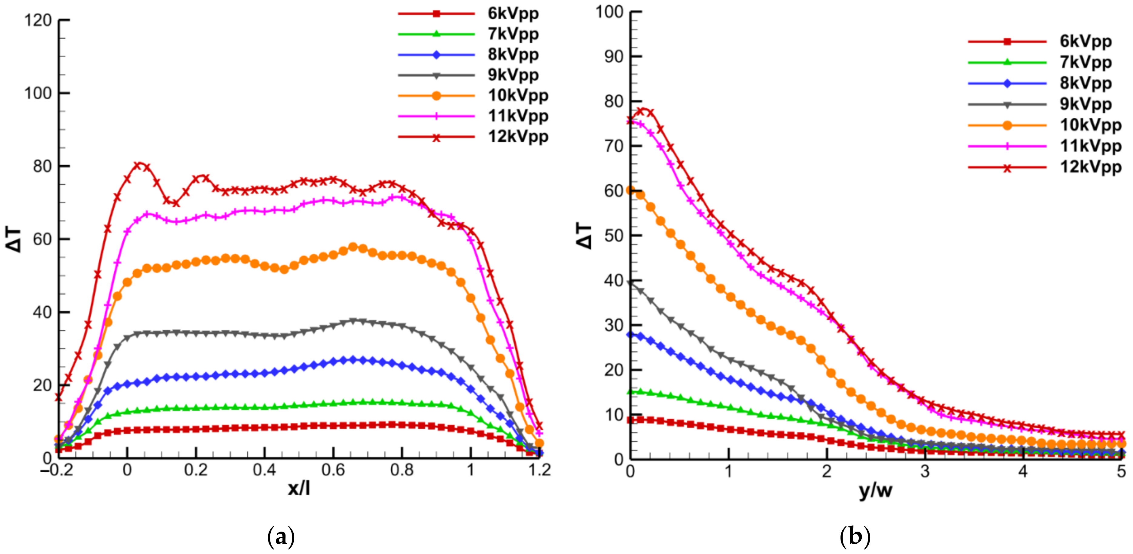
3.1. Thermal Effects Induced by Dielectric Barrier Discharge Plasma Actuators

Although most of the initial studies mainly considered the aerodynamic plasma effect and neglected the heat dissipation phenomenon, we now know that a large percentage of the power applied to the DBD plasma device is dissipated in the form of heat. In fact, only a very small fraction of the power applied to the actuator is transferred to the adjacent air as kinetic energy. As explained by Kriegseis et al. [150] and Roth et al. [151,152], and illustrated in Figure 7, the total power delivered to the DBD plasma actuator is composed of the reactive power, the power consumed in dielectric heating, the power expended to maintain and promote the plasma discharge, and, finally, the fluid mechanic power delivered to accelerate the adjacent air.
As we know, the reactive power is the complex power that represents the energy stored and retrieved by the load. Thus, it consists of the power that is continuously absorbed by the actuator and returned to the energy source. When dielectric materials are under the action of direct current, the DC conduction current is negligible if they are good insulators. However, this is not the case when a dielectric is under the action of an alternating electric field, as is the case with DBD plasma actuators. When an appreciable AC current is in phase with the electric field, part of the power is dissipated as dielectric heating due to the phenomenon of dielectric hysteresis, which is similar to hysteresis in ferromagnetic materials [153,154]. Due to this effect, the dielectric layer of the plasma actuator can consume a considerable amount of heat, usually referred to as dielectric power dissipation, which can be estimated as follows:
P l = U 2 2 π f A d ε R ε 0 tan δ .
where Pl is the power loss in the dielectric materials, U is the voltage, f is the frequency, A is the area, d is the distance of the electrodes, meaning that in a plasma actuator will be given by the dielectric layer thickness, εR is the relative permittivity of the dielectric, ε0 is the permittivity of vacuum, and tang(δ) is the dielectric loss factor.
During plasma discharge, electrons move from the exposed electrode to the di-electric surface in the first half of the AC cycle and back in the next half. During this movement, the electrodes collide with the neighboring particles and generate two plasma micro-discharges per AC cycle [155,156]. Due to this repetitive motion, a significant percentage of energy is also dissipated by elastic collisions of electrons, vibrational excitations, collisions between ions and neutral molecules, and thermal energy transferred from electrons to neutral particles [98,157]. This power consists of the power required to continuously maintain the plasma discharge. Finally, some of the power is transferred to the adjacent air as fluid mechanical power, which imparts momentum to the adjacent particles, accelerating them downstream in a tangential direction toward the surface. In general, this power is quantified by considering it as the equilibrium of the flow rate of the kinetic energy density [158,159,160] and is expressed by:
P m = 0 1 2 ρ v Y 3 l d Y .
where Pm is the mechanical power of the fluid, ρ is the air density, v(Y) is the velocity profile, and l the length of the plasma discharge.
The works of Roth et al. [109,151] can be considered the first works to show the various sources of power loss, with emphasis on dielectric heating. Later, in the study of Dong et al. [161], although the focus of the work was not on a thermal analysis of DBD plasma actuators but on the study of the aerodynamic performance of these devices under subsonic flow, the authors calculated the energy lost in the dielectric and experimentally measured the vibrational and rotational temperatures of the plasma using spectroscopic emission measurements. In the same year, Jukes et al. [162] studied the jet flow induced by dielectric barrier discharge plasma actuators and, additionally, applied thermal imaging techniques to estimate the surface temperature of the dielectric material due to plasma operation. By analyzing the results obtained and considering various assumptions, an analytical formula for estimating the plasma gas temperature was derived. However, in a later work by Joussot et al. [163], it was shown that the formula derived by Jukes et al. [162] did not provide sufficiently accurate results for the plasma gas temperature. Joussot et al. [163] performed thermal infrared measurements to determine the dielectric surface temperature when the plasma was turned on and after the discharge was turned off. Similar to the work of Jukes et al. [162], but with much greater emphasis on analyzing the gas temperature distribution, Stanfield et al. [164] experimentally determined the rotational and vibrational temperature distributions as a function of voltage. They concluded that the rotational temperatures for N2 and N2+ decrease in the induced flow direction and increase with the increase in the applied voltage.
Later, various authors began to focus more on the use of infrared thermal cameras to characterize the surface temperature of plasma actuators in order to analyze in depth the thermal effects of DBD plasma actuators. Tirumala et al. [165] performed infrared temperature measurements for plasma actuators with different dielectric thicknesses and for different glow states provided by different input voltage waveforms. In turn, Rodrigues et al. [166] experimentally investigated the influence of dielectric thickness and type of dielectric material on the surface temperature field of plasma actuators operated at different voltages. In a follow-up work, Rodrigues et al. [167] additionally studied the influence of an external flow on the surface temperature field of plasma actuators with different dielectric thicknesses and different dielectric materials.
A typical surface temperature contour of a DBD plasma actuator is shown in Figure 8. This figure shows the surface temperature field of a plasma actuator operated at quiescent conditions and under the influence of an external flow. As can be seen in this figure, the temperature of the top surface of the plasma actuator increases significantly due to the plasma discharge. The highest temperatures are measured at the onset of plasma formation near the exposed electrode. At quiescent conditions, the area of the exposed electrode has a similarly high temperature as the area where the plasma starts, due to the good thermal conductivity of the material of the exposed electrode. Under the influence of an external flow, however, the temperature values decrease along the entire actuator surface, with the area of the exposed electrode showing a significantly greater decrease.
In addition, Figure 9 shows the spatial temperature variation along the top surface of the plasma actuator for different input voltage levels. As we can see, the temperature along the x-axis is higher and almost constant between x/l = 0 and x/l = 1, which corresponds to the region of plasma formation. The temperature increases with increasing applied voltage, and at higher voltages, the temperature profile starts to oscillate more, which means that the plasma discharge becomes more and more filamentary. In the y-direction, the highest temperatures are found near the exposed electrode edge and decrease in the y-direction.
Later, Abbasi et al. [168] studied the thermal properties of plasma actuators in a turbulent boundary layer using infrared thermography and presented transient thermal results. They also investigated the effect of duty cycle on the thermal properties of plasma actuators and concluded that they exhibit strong oscillatory temperature variations at low frequencies in the range of 5–10 Hz, while at higher frequencies, a similar effect to continuous operation occurs. Recently, Kaneko et al. [169] also studied the thermal effects of plasma actuators using infrared thermal imaging to understand the effects of the shape of the exposed electrode. They demonstrated that the topology of the discharge differs between plate and wire electrodes, and, therefore, the surface temperature fields also show differences. The surface temperature measurements and thermal property analysis performed in the above studies have shown that plasma actuators cause a significant increase in the surface temperature of the dielectric. The temperatures determined in these studies are significantly higher than the solidification temperature of water, demonstrating the potential of plasma actuators to prevent ice formation and accumulation on the surface on which they are used.
Due to the nature of the plasma discharge, which results from the use of high voltage and the generation of a high electric field, several conventional measurement techniques, such as thermocouples, cannot be used directly because of the strong electromagnetic interference. In view of this, Rodrigues et al. [98] proposed a new calorimetric technique to quantify the thermal power generated by DBD plasma devices. In this technique, a thermally isolated duct with a fan at the inlet is used to generate a constant axial airflow. The plasma actuator is placed in the airflow calorimeter and the temperature is measured without plasma discharge and after a certain operating time with plasma discharge. Using the basic calorimetric law and applying it to this particular case, the thermal power generated by the dielectric barrier discharge can be estimated by the following equation:
P t = ρ Φ C p Δ T .
where Pt is the thermal power generated by the plasma device, ρ is the air density, Φ is the air flow rate, Cp is the specific heat of the air at constant pressure, and ΔT the temperature variation in the air due to the plasma discharge operation. This experimental technique was used in the works of Rodrigues et al. [98,114] to estimate the thermal power generated by DBD plasma actuators made of different dielectric materials and different dielectric layer thicknesses. In addition, they also estimated the dielectric power loss using the analytical formula previously published in Roth et al. [151]. Figure 10 shows the ratio of active power, thermal power, and dielectric power loss for actuators made of 0.3 mm Kapton and 1.02 mm Kapton operated at different voltages.
Figure 10 shows that plasma actuators dissipate a large percentage of power as thermal energy, regardless of dielectric thickness. Rodrigues et al. [114] studied the thermal power generated by actuators with different dielectric materials and concluded that depending on the dielectric material, 60% to 95% of the power applied to the actuator is released as thermal energy. This proves once again the potential of plasma actuators to prevent ice formation or promote local ice melt. Most studies dealing with the thermal effects of dielectric barrier discharge have been performed experimentally, but some numerical studies can also be found in the literature. Aberoumand et al. [170] numerically investigated the effects of various DBD plasma actuator arrangements on the temperature field in a channel flow, and Benmoussa et al. [171] numerically investigated the phenomenon of gas heating in dielectric barrier discharges due to the Joule heat effect for Ne–Xe gas mixtures. Recently, Zhang et al. [172] conducted a detailed review of recent developments in the thermal properties of dielectric barrier discharge surface plasmas and demonstrated the potential of these devices to produce significant thermal effects that can be used for deicing and ice prevention applications.

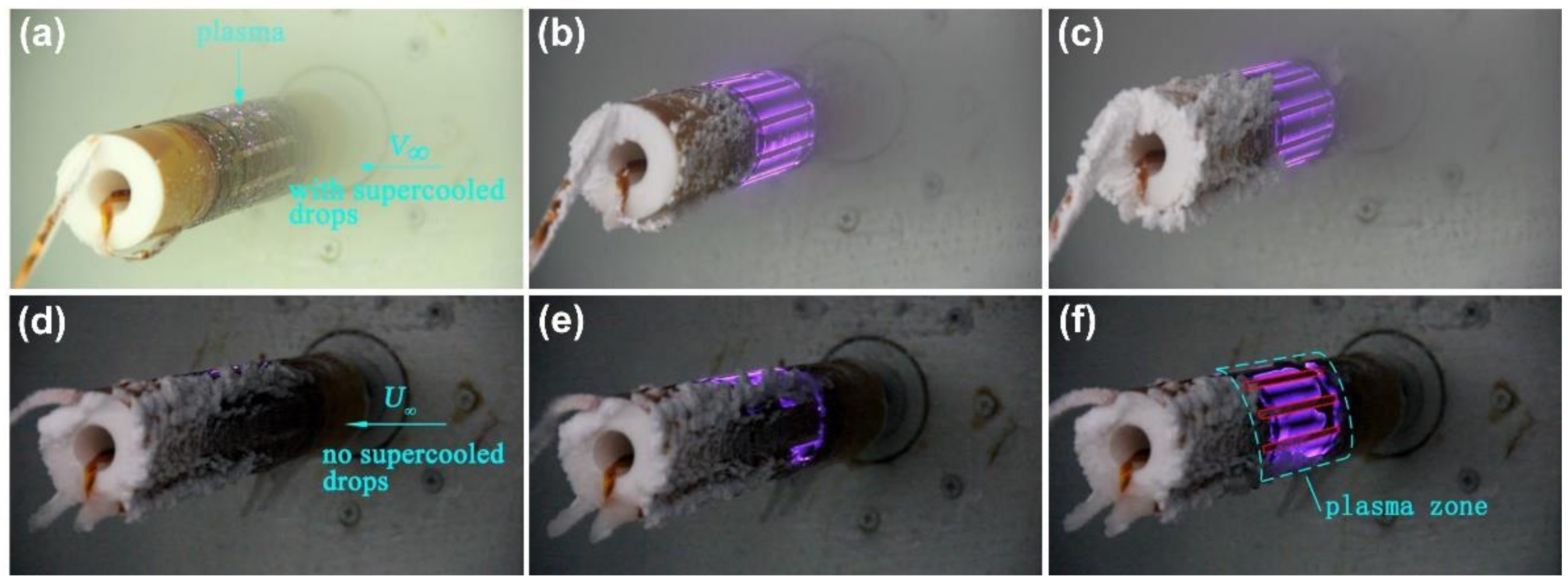
3.2. Plasma Actuators for Deicing and Ice Formation Prevention

Prevention of ice formation or deicing is an extremely important process in various industries. In particular, in the global aviation sector, ice formation on the surface of aircraft causes various types of alarms, ranging from environmental damage, as it affects aerodynamics and leads to an increase in fuel consumption and pollutant emissions, to catastrophic accident situations, as it can cause mechanical and electrical malfunctions [173,174]. Similarly, in the wind energy market, ice accumulation on the rotor blades leads to large loads on the wind tower, causing significant losses in power generation, dangerous ice throw around the turbine, and even structural failure [175]. Considering that a significant percentage of the energy supplied to DBD plasma actuators is converted into heat dissipated from their surface, as described in the previous section [98,114], these devices have been proposed as a viable alternative to prevent ice formation and/or deicing of aerodynamic components in various applications. Recent literature has reported on various configurations of DBD plasma actuators used in different systems and tested under different conditions.
The study by Cai et al. [29] is one of the first experimental reports on the use of DBD plasma actuators for deicing and anti-icing. The authors installed handmade plasma actuators on a cylinder model surface subjected to supercooled flow in a wind tunnel. The DBD plasma actuators consisted of a 0.33 mm thick Kapton dielectric layer (six 0.056 mm thick stacked) and two 0.03 mm thick asymmetric copper electrodes with 3.3 and 10 mm wide exposed and encapsulated electrodes, respectively. The actuators were coupled to a Teflon cylinder (45 mm diameter and 220 mm length), without spacing, in a multiple actuator configuration covering ≈80 mm of the cylinder length, as shown in Figure 11.
The deicing and anti-icing tests were performed in a closed-circuit icing wind tunnel, where the airflow velocity (U) could range from 5 to 18 m/s and the air temperature (T) from −25 to 30 °C. The anti-icing tests, conducted at a wind speed of 15 m/s and with the actuator supplied at 15 kVpp and 13.4 kHz, showed that after 16 min of actuation, no ice accretion occurred on the cylinder surface covered by the DBD, while clear ice formed in the uncovered zone (Figure 12a–c). Deicing tests, conducted after the wind tunnel was operated for 15 min with the spray of supercooled droplets, showed complete removal of the 5 mm thick ice layer after 150 s of plasma actuation at 15 kVpp and 13.4 kHz and at constant airflow velocity and temperature (Figure 12d–f).
Liu et al. [149] investigated the use of thermal effects induced by a DBD plasma actuator for aircraft icing mitigation compared to conventional electrical heating. Both systems were installed in parallel in a NACA 0012 airfoil with a chord length of 150 mm (Figure 13a), made of hard-plastic material through 3D printing rapid prototyping, and tested in an icing research tunnel with a wind speed capability of 60 m/s and airflow temperature as low as −25 °C, equipped with atomizing spray nozzles capable of injecting water droplets with mean volume diameter (MVD) ≈20 μm, allowing the liquid water content (LWC) in the tunnel to be adjusted. The DBD plasma actuator consisted of four encapsulated copper electrodes (350 mm length × 10.0 mm width) and five exposed copper electrodes (96 mm length × 3.0 mm width) with a thickness of 70 mm and zero overlap gap, separated by three layers of Kapton 130 μm thick. The four encapsulated electrodes were evenly distributed over ≈27% of the chord length of the airfoil and were spaced 3 mm apart each (Figure 13b).
The first exposed electrode near the leading edge had a smaller width of 5.0 mm to generate more plasma in this area. The conventional electrical film heater consisted of an etched foil element with a thickness of 0.013 mm encapsulated between two layers of 0.05 mm thick Kapton film and 0.025 mm thick FEP adhesive tape over a total area of 50.8 × 101.6 mm. Prior the start of the tests, the icing tunnel was operated at −5 °C for 60 min to ensure a thermal steady state. The tests were performed at U = 40 m/s, T = −5 °C, and LWC = 1.0 g/cm3. The power density of the two devices was kept constant and equal to 15.6 kW/m2. The thermal profiles of both systems in operation were obtained through an infrared thermal imaging camera. In the first test phase, the DBD and the electric film heater were turned on for 60 s. After 10 s, the temperature of the DBD electrodes increased by about 10 °C, while the temperature of the dielectric layer (in the spaces between the electrodes) remained below 0 °C (Figure 14a). After 60 s of operation, thermal equilibrium was reached for both devices (Figure 14b). From 60 s (instant t0 in Figure 14c,d), the water spray system was connected, and it was found that after 25 s, the impingement of the supercooled water droplets on the airfoil caused a significant temperature drop in the electric film heater, while the temperature of the DBD plasma actuator dropped only slightly (Figure 14c). After 200 s, the temperature of both devices practically did not change, indicating that thermal equilibrium was reached (Figure 14d), which in turn means that the energy supplied to the devices was sufficient to prevent ice accumulation on the airfoil.
In the context of this study, another report by Liu et al. [176] compared the actuation of DBD plasma actuators with conventional electrical heating using the same experimental setup and conditions as reported in [149]. The reported results are consistent with the previous information. Only after 200 s of operation did ice begin to form at a nearby plasma discharge site. In view of these results, the authors considered that the DBD plasma actuator-based method had a more promising performance compared with the conventional electrical heating method, because the temperature drop on the DBD surface was much lower. This difference was explained by the fact that the water droplets were heated not only by heat conduction but also by heat convection as they moved through the hot air above the DBD (Figure 15).
This half–half configuration (similar to [149]) was previously used by Zhou et al. [28] in a study designed to demonstrate the effectiveness of DBD plasma actuators as deicing and anti-icing devices. DBD plasma actuators, based on three layers of Kapton with a thickness of 130 μm and multiple exposed and encapsulated copper electrodes with a thickness of 70 μm, were symmetrically placed in the middle of a NACA 0012 airfoil (half on and half off). The system was exposed to typical glaze ice conditions (U = 40 m/s, T = −5 °C; LWC = 1.5 g/m3) and rime ice conditions (U = 40 m/s, T = −15 °C; LWC = 1.0 g/m3). In the half where the DBD plasma actuators were turned off, ice formed shortly after the start of the experiments, while in the half where the DBD were turned on, ice formed only in the region downstream of the covered area. This is a common problem in thermal based anti-icing and deicing systems, for which some authors propose a hybrid solution combining DBD with hydrophobic/icephobic coatings, which will be discussed later.
Chen et al. [177] evaluated the anti-icing performance of a nanosecond surface dielectric barrier discharge (NS-DBD) and investigated the effect of pulse frequency and voltage amplitude on actuation performance. The NS-DBD plasma actuator is a device driven by repetitive high voltage pulses with fast rise times on the order of nanoseconds [178]. The NS-DBD consisted of exposed (2 mm wide) and buried (10 mm wide) electrodes with thickness of 0.027 mm separated by three layers of Kapton tape as a dielectric layer (0.24 mm thick) (Figure 16a). The device was installed on an aluminum airfoil model NACA 0012 with a chord length of 280 mm and a spanwise length of 145 mm, as shown in Figure 16b. The airfoil was covered with a film 2.5 mm thick PTFE (polytetrafluoro-ethylene) to prevent heat transfer between NS-DBD and the airfoil structure.
Experiments were performed in an icing research tunnel under conditions of U = 65 m/s, T = −10 °C, LWC = 0.5 g/cm3, and MVD = 25 μm. The wind tunnel was turned on 1 h before the experiments to reach a steady state, then, the NS-DBD plasma actuator was turned on for ≈100 s (t = 0 s) to reach thermal equilibrium, and finally, the water sprayer was activated. To understand the effects of the discharge conditions, experiments with higher voltage amplitude and lower pulse frequency (HV-LF) and discharges with lower voltage amplitude with higher pulse frequency (LV-HF) were performed. Dynamic evaluation of anti-icing, with continuous impact of supercooled water droplets, showed that for the same input voltage, the LV-HF discharge performed better than the HV-LF discharge, as shown in Figure 17.
In the LV-HF discharge (Figure 17a), it was found that the supercooled droplets that hit the airfoil on the surface of the NS-DBD melted and flowed backward and, in turn, ice was formed in the areas of the airfoil that were not covered by the plasma actuator. In the discharge HV-LF (Figure 17b), ice accretion was detected even in the NS-DBD zone, first between the electrodes and at the end along the entire leading edge. The authors suggested the existence of a threshold frequency corresponding to the voltage amplitude of actuation signal and the incoming flow condition, which determined the anti-icing performance.
Following NS-DBD, Kolkbair et al. [179] reported the investigation of a hybrid system for deicing and anti-icing based on the combination of a NS-DBD plasma actuator and a superhydrophobic surface (SHS) coating on the airfoil surface. The exposed (≈95 mm wide) and grounded electrodes of the NS-DBD plasma actuator were made of copper tape ≈ 70 μm thick separated by a PVC (polyvinyl chloride) dielectric layer ≈ 0.3 mm thick. The device was coupled to a 3D-printed NACA 0012 airfoil with a chord length of 150 mm, in a configuration similar to that presented in [177], and, finally, was painted with enamel. To test the SHS, some prototypes were sprayed with the superhydrophobic coating Hydrobead on the top of enamel, according to the procedure described in [180]. The hydrophobized surfaces showed a significant increase in the static contact angle from ≈65° to ≈157° for the Enamel and Hydrobead surfaces. The experiments were conducted in an icing research tunnel (the same as in [149]), and the temperature map during ice accretion was obtained using an infrared thermal imaging system. Tests were conducted at U = 40 m/s, T = −5 °C, and LWC = 0.8 g/cm3, and it was found that ice formed on the leading edge of the airfoil when the actuator was off, despite the hydrophobic treatment. In turn, when the NS-DBD was turned on at V = 14 kV, f = 2 kHz, and P = 175 W/m, the supercooled water droplets formed ice at the leading edge only after 60 s, but the backward-flowing water froze on the airfoil surface and formed rivulets from ≈30 s of experimental time. For the actuation conditions of V = 14 kV, f = 4 kHz, and P = 350 W/m, an ice-free leading edge was observed, but ice rivulets appeared on the back surface after ≈30 s. Finally, at a plasma actuation of V = 14 kV, f = 6 kHz, and P = 525 W/m, there was no ice formation at either the leading edge or at the trailing edge of the airfoil. It should be emphasized that for untreated airfoil surfaces, ice accretion was observed at the leading edge and at the trailing edge for all input conditions tested. The authors concluded that the combination of NS-DBD plasma actuation and SHS coating effectively prevents ice accretion on the entire structure of the airfoil.
Actuator surface wettability was also addressed in the study by Zheng et al. [181], where the effect of a hydrophobic coating on the dielectric layer of a SDBD plasma actuators was studied. Two types of dielectric layers were prepared, one of ordinary quartz (1 ± 0.01 mm thick) and another of SiC treated quartz glass, both with exposed electrodes (5 × 50 mm) and buried electrodes (15 × 40 mm) in copper foil (0.03 mm thick) arranged in an asymmetric configuration. The measured contact angle of the SiC-treated surface was 119.5°, about five times higher than that of the ordinary quartz glass surface. The static deicing experiments at 10 kV and 6 kHz showed that the SiC-coated actuator melted an area of 7.1 cm2 of ice after 60 s of experiment time, while the quartz glass actuator melted 9.2 cm2, with the estimated power consumption of the SiC-coated actuator being 7.35 W, while the uncoated quartz glass actuator consumed 14.7 W. Therefore, the efficiency of the SiC-coated actuator after 60 s was 0.996 cm2/W, which was 54.31% higher than that of the uncoated actuator (0.626 cm2/W).
Returning to the scope of the NS-DBD, Liu et al. [182] also evaluated the anti-icing and deicing performance of these devices for in-flight ice mitigation of aircraft. The experiments were conducted in the same icing research tunnel used in [149], and the plasma actuators were fabricated with five layers of PVC as the dielectric layer (≈100 μm thick per layer), one exposed electrode, and nine encapsulated electrodes, all with the same thickness and length of about 70 μm and 125 mm, respectively. The device was coupled to a NACA 0012 airfoil model (150 mm chord length) fabricated by 3D printing from hard plastic in a half–half configuration of the NS-DBD plasma actuator with plasma on versus plasma off, as shown in Figure 18.
Ice accretion tests were performed under different temperature (−15 to −5 °C) and frequency (2 to 6 kHz) conditions, keeping U = 40 m/s and LWC = 1.0 g/cm3 constant. As in the previous study, the authors found that increasing the operating frequency of the NS-DBD plasma actuator significantly improved the anti-icing and deicing performance. As shown in Figure 19a, the supercooled water droplets impinging on the wing surface quickly formed an ice layer around the leading edge at 2 kHz, while almost no ice formed around the leading edge of the wing airfoil at 6 kHz (Figure 19b), largely due to the higher thermal energy generation at higher operating frequency. Regarding the temperature effect, the authors found that the plasma actuation showed better anti-icing and deicing performance at warmer air temperatures of T = −5 °C for the same frequency input signal.
In another study by Liu el al. [183], the use of a DBD plasma actuator operating in duty cycle mode was tested for aircraft ice mitigation and compared with a DBD operating in continuous mode. The authors used a NACA 0012 airfoil, fabricated by 3D printing from hard plastic, as the wing profile, with DBD plasma actuators installed in a half–half configuration, similar to Figure 19 from [182], with each half used for the respective type of actuation. The DBD consisted of four encapsulated electrodes and five exposed electrodes (70 μm thick) separated by three layers of Kapton film (130 μm thick). The exposed electrodes were evenly distributed on both halves of the wing profile with 3 mm spacing. The airfoil was tested in an icing research tunnel at U = 40 m/s, LWC = 1.0 g/cm3, and T = −5 °C, and it was turned on 60 min (t0) before testing to ensure steady-state conditions. The results showed that using duty cycle mode with a modulation frequency of 1 Hz exhibited better anti-icing performance at the same power input. Figure 20 shows that the DBD operated in duty cycle mode was ice-free by the end of the 140 s of test, while the conventional actuator had an ice film in the plasma zone after about 20 s of testing. The authors also demonstrated that increasing the duty cycle modulation frequency increased the heat dissipation of the DBD, thus improving its anti-icing and deicing capabilities.
An interesting anti-icing approach, based on the so-called “heat knife”, was proposed by Wei et al. [119]. The authors developed a device based on a series of surface dielectric barrier discharge (SDBD) plasma actuators in a specific configuration, which they called the “stream-wise plasma heat knife” (see Figure 21).
According to the authors, in this configuration, when the device was powered by a high-voltage source, the generated plasma rapidly gave off heat around the discharge, allowing a fast thermal response that quickly heated the water droplets impinging on the “stream-wise plasma heat knife”. The device was installed in the NACA 0012 airfoil model (280 mm chordwise length and 300 mm spanwise length), wrapped with a 2-mm thick polyimide film for thermal and electrical insulation, and tested in an icing research tunnel at LWC = 0.5 g/cm3, MVD = 25 μm, U = 65 m/s, and two temperatures of −5 and −15 °C. The “stream-wise plasma heat knife”, which consisted of a dielectric layer of 0.15-mm-thick Kapton tape separating the exposed (2-mm-wide) and encapsulated (10-mm-wide) electrodes made of 0.06-mm-thick copper foil, was operated with a nanosecond pulsed power with a peak voltage of 7.7 kV and frequency of 6 kHz. The typical snapshots of the time evolution of the dynamic ice accretion experiments (Figure 22) showed that at T = −5 °C, there was no ice formation in the plasma region after 180 s. At T = −15 °C, a small ice layer appeared between two exposed electrodes after 90 s, but it did not grow further or disappear over time. Under both conditions, ice accumulated in the plasma-free region.
In an identical report, Wei et al. [184] studied the removal of 3 mm thick ice accumulated on the surface of a nanosecond pulsed surface dielectric barrier discharge (nSDBD). The apparatus and experimental setup were similar to that used in [119], and tests were performed under typical glaze icing conditions: LWC = 0.5 g/cm3, MVD = 25 μm, U = 65 m/s, and T = −5 °C. The nSDBD was connected after 90 s of ice formation on its surface (≈3 mm thick), and it was found that melting of the ice started immediately after the plasma discharge started, and the whole process took about 4 s. Moreover, ice accretion in the plasma region did not repeat during the rest of the experiment. The authors concluded that the thermal effects together with the aerodynamic force contributed to the good deicing performance of the nSDBD plasma actuator.
Fang et al. [185] also discussed the concept of the “heat knife” and proposed the plasma streamwise heat knife approach for anti-icing purposes. Two types of configurations were experimented with the same number of streamwise exposed electrodes (3 mm wide) spaced 10 mm apart and all connected by a spanwise electrode strip (5 mm wide). In configuration 1, the connecting strip separated the streamwise electrodes symmetrically, while in configuration 2, the connecting strip was placed at the end of the streamwise electrodes, as shown in Figure 23.
The electrodes were made of a 0.06-mm-thick copper foil and a 0.18-mm-thick dielectric layer of Kapton tape. The devices were attached to the leading edge of a NACA 0012 organic glass airfoil (Figure 23) and tested in an icing wind tunnel with constant ice conditions of U = 20 m/s, T = −15 °C, LWC = 1 g/m3, and MVD = 40 μm and electrical conditions of 9 kVpp and 6 kHz. Configuration 2 showed better anti-icing performance than configuration 1, because it was ice-free on most of the surface covered by the actuator, unlike configuration 1, where an ice ridge formed on the spanwise electrode. Based on these results, Su et al. [186] proposed a three-level electrode configuration by reformulating configuration 2 to improve heating under severe icing conditions. Anti-icing tests were conducted in an icing wind tunnel (U = 65 m/s, T = −15 °C, LWC = 0.5 g/cm3, MVD = 25 μm) with a power consumption of 70 W. It was found that the reconfigured three-level heat knife achieved better anti-icing results than the original configuration at the leading edge of the airfoil, but a significant ice ridge was formed at the trailing edge.
Meng et al. [187] compared the anti-icing efficacy of three types of SDBD plasma actuators, each designed for a different type of actuation: type-1 to generate induced flow in the same direction as the incoming flow, type-2 to generate induced flow in the opposite direction of the in-coming flow, and type-3 to generate induced jets in the vertical direction. All actuators consisted of 0.07 mm thick copper electrodes separated by three 0.13 mm thick Kapton layers. The arrangement and size of the electrodes varied depending on the configuration: four exposed electrodes (5 mm wide) and four buried electrodes (5 mm wide) for type-1 and type-2, and five exposed electrodes (3 mm wide) and four buried electrodes (5 mm wide for the first and 10 mm wide for the others) for type-3, as shown in the cross-sectional images of the airfoils shown in Figure 24. The SDBD actuators were coupled to a model of a NACA 0012 airfoil (0.15 m chord length and 0.4 m span length) in a half–half configuration, similar to that used in [182], with two separated plasma on and plasma off zones. The device was tested in an icing wind tunnel under the conditions of U = 40 m/s, LWC = 1.0 g/cm3, and T = −5 °C. The configuration that induced perpendicular flows (type-3) achieved the best anti-icing performance by ensuring no ice accumulated on the entire underside of the airfoil, while the configurations with induced flows in the same (type-1) and opposite (type-2) directions were 57% and 81% of the airfoil chord length ice-free (Figure 24).
Kolbakir et al. [188] also studied and compared the performance of different configurations of anti-icing DBD plasma actuators, arranged in different orientations and varying the number and width of exposed electrodes. The actuators were constructed with a PVC film of ≈400 μm thickness on the dielectric layer and a copper tape of ≈70 μm thickness on the electrodes. The exposed electrodes were all the same length (72 mm) and the width varied from 4.00 to 60.0 mm depending on the test case. The DBD were tested in an icing research tunnel (U = 40 m/s, T = −5 °C, LWC = 1.5 g/m3) coupled to a NACA 0012 airfoil model (150 mm chord length and 400 mm span length) in streamwise and spanwise layouts. The streamwise layout resulted in higher plasma-induced surface heating and, thus, better anti-icing performance than the spanwise layout. Streamwise actuators prevented ice accretion not only at the leading edge, but also on the trailing edge of the airfoil, as the surface heating delayed the runback ice formation.
Lindner et al. [189] investigated the effect of electrode type and electrode configuration on the anti-icing performance of SDBD actuators. The authors developed SDBD plasma actuators using microelectromechanical systems (MEMS) technology and compared the performance with SDBD fabricated by printed circuit board (PCB) technology. The anti-icing and deicing experiments were conducted in an icing wind tunnel at U = 27 to 50 m/s, T = −18 to −20 °C, LWC = 3 g/m3, and MVD = 20 μm. Different materials were used for the dielectric layer of the SDBD actuators: FR4 TG135 (500 μm thick) in PCB and zirconia (150 μm thick) and borofloat glass (500 μm thick) in MEMS. It was concluded that a smaller thickness of MEMS SDBD electrodes (0.3 μm) compared to the 35 μm thickness of PCB SDBD favored the anti-icing performance, as shown in Figure 25. Moreover, the anti-icing effect is independent of the ionic wind generated, so the thickness of the substrate can be reduced. Titanium was also identified as the most suitable material for electrode fabrication. The authors suggested that the density of the electrodes and the thickness of the dielectric layer play a crucial role in the effectiveness of the device.
The ice shape modulation method on the leading-edge airfoil was studied by Jia et al. [190] using nSDBD. The actuators were constructed with a dielectric Kapton layer (0.18 mm thick), and exposed (3 mm wide) and encapsulated (5 mm wide) copper foils (0.027 mm thick) electrodes were installed on a NACA 0012 plexiglass airfoil (800 mm spanwise length and 200 mm chord length) and tested in an icing wind tunnel under glaze ice conditions (LWC = 1.5 g/m3, MVD = 25 μm, T = −5 °C, U = 65 m/s) and under frost ice conditions (LWC = 0.5 g/m3, MVD = 25 μm, T = −15 °C, U = 65 m/s). Using nSDBD ice shape modulation, the continuous ice at the leading edge of the airfoil was periodically modulated into segmented ice pieces. Under glaze ice conditions, the ice on both sides of the deicing zone began to coalesce after 360 s, while under frost ice conditions, this occurred after 270 s. The authors concluded that the ice shape modulation method can reduce energy consumption by more than 50% compared to full deicing.
Abdollahzadeh et al. [111] developed a parametric optimization of DBD plasma actuators for ice sensing and deicing performance. The DBD were built with a 0.3 mm thick Kapton layer, a 20 mm wide embedded copper electrode, a 5 mm wide exposed copper electrode, and a 0 mm gap between the electrodes. For deicing tests, the DBD surface was covered with an 8 mm thick ice layer, and the actuator was operated at 4 kVpp and 24 kHz (Figure 26a). After 1550 s, the ice layer detached from the DBD surface, and a large hole was formed. The authors considered that the melting process was complete at this point (Figure 26b). Soft ice (6 cm × 10 cm × 1.7 cm, Figure 26c) was also tested in deicing experiments, and it was observed that the frost layer was completely melted after about 780 s (Figure 26d).
Gao et al. [191] presented an innovative plasma synthetic jet actuator (PSJA) concept for ice mitigation, as an alternative to the usual SDBD-based deicing and anti-icing systems. Deicing experiments were conducted at a room temperature of 10 ± 2 °C, and the system was found to be effective in removing free columnar ice layers of 200 mm diameter and 3, 8, and 10 mm thickness in the different failure modes of radial and circumferential crushing, radial and circumferential cracking, and radial cracking. For improving the deicing efficiency of plasma actuators over an airfoil, Hu et al. [192] performed an optimization study for the implementation of plasma actuators on a realistic configuration of the NACA0012 airfoil model and emphasized that the biggest advantage of the AC-SDBD plasma actuator is that it can be simultaneously used for flow control and ice mitigation using the same device, meaning that the actuators can be used for icing control in icing conditions and flow control in the non-icing environment. Recently, Tanaka et al. [193] performed an experimental study about snowfall flow control using a high-durability designed plasma electrode, and Lilley et al. [194] studied the effects of water adhesion from droplets directly sprayed onto a plasma actuator and its plasma glow recovery.
Various forms of deicing and anti-icing actuation based on dielectric barrier discharge were presented and discussed. The prevention of ice accretion is becoming a leading application for DBD plasma actuators; however, the fact that these devices are multi-functional and have a prominent application in active flow control to suppress boundary layer separation and/or delay airfoil stall, which improves aerodynamic performance, should not be underestimated. At the same time, they can be used as effective deicing and/or anti-icing devices to prevent ice accumulation on the airfoil surface and ensure safer and more efficient operation [188].

3.3. Ice Sensing by Dielectric Barrier Discharge Plasma Actuators

In addition to the possible use of plasma actuators as active flow control and deicing devices, Abdollahzadeh et al. [195] recently disclosed the possibility of using these devices as ice sensors. In this work, the authors explain that since plasma actuators behave similarly to a capacitor, they can also be operated as capacitive ice sensors and detect the presence of water, air, or ice on their top surface. The properties of water are different in different states of matter, i.e., the dielectric constant of ice is different from that of liquid water. When we apply an alternating current to the plasma actuator, an electric field is generated on the top of the dielectric layer, in the region between the exposed electrode and the covered electrode. This electric field is affected by the medium on top of the dielectric layer; since air, water, and ice are media with different properties and different dielectric permittivity, the presence of water or ice on the surface of the actuator changes the electric field and, consequently, the different electric parameters of the actuator, such as charge or capacitance. Therefore, by monitoring the electrical properties of the DBD plasma actuator, it is possible to detect the presence of air, ice, or water on the top surface of the plasma device and, in this respect, to operate the device as an ice sensor. Abdollahzadeh et al. [30] experimentally investigated the operation of a DBD plasma actuator as a simultaneous deicing and ice sensing device and demonstrated that their electrical properties change significantly when the medium adjacent to the actuator surface is changed. Figure 27 shows the change in the electrical properties of a single DBD plasma actuator due to the change in the properties of the adjacent medium.
Figure 27a shows that the charge variation along the voltage cycle changes significantly due to the presence of air, ice, or water on the top of the actuator. In the presence of air, the voltage–charge curve is narrower, and the maximum and minimum charges have lower absolute values. The absolute charge values increase in the presence of a layer of ice and become even larger in the presence of a thin film of water. In Figure 27b, we see that DBD plasma actuators can also be used as ice sensors to monitor the melting process of a thin ice layer over time. Figure 27b shows that in the first phase, both the charge and the capacitance increase, which means that the ice is melted and the fraction of liquid water increases with time. In phase 2, a sudden decrease in the values of charge and capacitance is observed, which means that the water between the ice and the actuator has been drained and the amount of ice/water on the actuator’s surface has been significantly reduced. In phase 3, a slower decrease in capacitance and charge values is still observed, which means that smaller pieces of ice are still removed. Abdollahzadeh et al. [30] demonstrated not only the potential of plasma actuators for ice sensing, but also that by using networks of multiple plasma actuators, it is possible to detect the position of the ice, since each actuator provides an individual signal. Later, in the study of Rodrigues et al. [118], this possibility was optimized by developing a new plasma actuator configuration characterized by a plasma actuator with multiple encapsulated electrodes that allows for detection of the position of the ice, or where there is a major ice accumulation. This configuration is shown in Figure 28 along with the monitoring voltage signals when the ice is placed on the left segment.
Figure 28b shows that when an ice cube is placed over one segment of the actuator while the other segments are kept ice-free, the monitoring voltage of that segment increases significantly, indicating that it is covered with ice. Since the monitoring signal of each segment is independent of the other segments, each segment operates as an independent sensor, and by knowing its position, it is possible to detect the specific position where ice accumulates. Recently, Abdollahzadeh et al. [111] performed a parametric study to understand the effect of dielectric material, dielectric thickness, exposed electrode width, embedded electrode width, and gap on the performance of the plasma actuator as an ice sensor. Rodrigues et al. [196] and Xie et al. [197] have conducted further studies to investigate the suitability of DBD plasma actuators for multipurpose applications and demonstrated that these devices are capable of performing ice sensing, deicing, and flow control simultaneously.

4. Conclusions

Ice accretion on aircraft and wind turbine surfaces is a major problem for both the aviation and wind power industries. For aircraft flying in cold conditions, the ice buildup phenomenon can be harmful for the normal operation of several aircraft components, including, for example, the aircraft wings. Ice accumulation on the leading edge of aircraft wings disturbs the flow and degrades aerodynamic performance by increasing drag and decreasing lift, which may seriously threaten flight safety. In a similar way, ice accretion is also a major problem for the wind power industry. Cold regions are very attractive for wind power generation, since these regions are usually associated with higher air density and higher wind speeds. However, these regions are also associated with favorable conditions for ice formation that affect and reduce wind turbine performance. In addition to the reduction in performance, the unbalanced loads caused by ice accumulation lead to deterioration of the components and a shortening of service life, which, in turn, considerably increases the maintenance costs of wind turbines. With this in mind, several works have been carried out over the years to study and further develop different ice protection systems. Ice protection systems include passive and active deicing and anti-icing techniques as well as ice sensing methods.
Active ice protection systems include the use of mechanical methods, the application of heat, the use of dry or liquid chemicals to lower the freezing point of water, or a combination of these different techniques. These methods include techniques such as pneumatic deicing boots, electrically resistive elements, electro-mechanical expulsion systems, thermo-mechanical expulsion devices, ultrasonic vibration methods, shape memory alloys, electromagnetically-induced vibration systems, thermal air bleed anti-icing systems, or chemical deicing devices. Passive ice protection systems, on the other hand, involve coatings or modifications to the surface structures to prevent or delay the ice accretion on the surface. These types of systems include hydrophobic or superhydrophobic coatings, micro- and nanoscale rough structures, and the combination of icephobic and hydrophobic coatings with electrothermal and auxiliary photothermal effects. Ice protection systems also involve the use of ice detection techniques which can be categorized in direct and indirect methods of ice detections. Indirect methods utilize some weather conditions such as temperature, humidity, and visibility combined with empirical deterministic models to predict icing events, while direct ice detection methods measure a change in a property such as mass, conductivity, inductance, and dielectric constants to estimate ice formation on the surface.
Recently, plasma actuators have been introduced as attractive devices for ice protection systems. These devices are capable of imparting momentum to the adjacent flow, which can be used to manipulate the local flow field. In addition, they have an instantaneous response time, are very lightweight, robust, easy to fabricate and implement, and consume low power levels. As demonstrated in the literature, these devices produce significant thermal effects which can be used for anti-icing or deicing purposes. The total power delivered to the DBD plasma actuator is composed of the reactive power, the power dissipated in dielectric heating, power spend to maintain and promote the plasma discharge, and, finally, the fluid mechanic power that is delivered to the adjacent air accelerating it. Different authors studied the actuator surface temperature field induced by the plasma discharge and concluded that the surface temperature increases significantly, especially at the onset of the plasma formation. At quiescent conditions, the exposed electrode region has a similar high temperature to the region where the plasma is generated due to the good thermal conductivity of the exposed electrode material. However, under the influence of an external flow, the temperature magnitudes decrease along the actuator surface, with the exposed electrode region showing a much larger decrease. In addition, researchers quantified the thermal power generated and concluded that plasma actuators dissipate a large percentage of power as thermal energy, regardless of the dielectric thickness. This thermal power released by the actuator is approximately 60 to 95% of the power supplied to the device, depending on the dielectric material. These results prove the potential of plasma actuators to avoid ice formation or promote local ice melting. Considering that a significant percentage of the power supplied to DBD plasma actuators is converted to heat dissipated from their surface, these devices have been proposed as a viable alternative to prevent ice formation and/or deicing in aerodynamic components in various applications. Various configurations of DBD plasma actuators have been reported in recent literature, applied to different systems, and tested under diverse conditions. Plasma actuators have been studied as deicing devices, and their ability to prevent ice accumulation on different objects, such as airfoils or cylinders, has been demonstrated. The performance of using plasma actuators as ice prevention systems was also compared to conventional electric heaters commonly used in ice protection systems. The studies showed that the DBD plasma actuator-based method presented a more promising performance compared to the conventional electrical heating method, because the temperature drop on the DBD surface was much lower. This difference was explained by the fact that the water droplets were heated not only by thermal conduction but also by thermal convection as they travel through the hot air above the DBD. In addition, various authors have also demonstrated the potential of using nanosecond plasma actuators for deicing and removal of ice from the surface. In line with these studies, it has also been shown that these devices can be combined with superhydrophobic surface coatings to improve the efficiency of the ice protection system. In addition, to improve the deicing efficiency of these devices, a new configuration called a “stream-wise plasma heat knife” has been proposed. Various works were developed considering this new configuration to improve its performance. Other works also addressed the study of different layouts, actuators positioning, and different types of electrodes and dielectric materials. In all the works, authors agreed on the ability of plasma actuators to efficiently perform deicing and ice prevention operations.
In addition to the potential use of plasma actuators as active flow control and deicing systems, these devices have recently been proposed as ice sensors. Since plasma actuators exhibit a behavior similar to a capacitor, they can also be operated as an ice capacitive sensor and detect the presence of water, air, or ice on their surface. When an alternating current is applied to the plasma actuator, an electric field is generated on the top of the dielectric layer in the region between the exposed electrode and covered electrode. This electric field is affected by the medium on top of the dielectric layer. Thus, the presence of water or ice on the actuator’s surface will alter the electric field in comparison to the electric field produced in air and, consequently, will also modify the different electrical parameters of the actuator, such as the charge or the capacitance. Therefore, by monitoring the electrical characteristics of the DBD plasma actuator, it is possible to detect the presence of air, ice, or water on the top surface of the plasma device and operate the device as an ice sensor. Considering all the works and findings explored in this paper, we may conclude that plasma actuators are ideal devices for ice protection systems, because the same device is able to perform anti-/deicing operations and detect ice accumulation. This eliminates the need for two different techniques for deicing and detecting ice accumulation. Furthermore, they still have the advantage of controlling flow and improving the aerodynamic performance, even when no deicing or ice prevention measures need to be implemented.

Author Contributions

Conceptualization, F.R. and M.A.; methodology, F.R., M.A. and J.N.-P.; investigation, F.R., M.A. and J.N.-P.; writing—original draft preparation, F.R., M.A. and J.N.-P.; writing—review and editing, F.R., M.A., J.N.-P. and J.P.; supervision, J.P.; project administration, J.P.; funding acquisition, F.R., M.A., J.N.-P. and J.P. All authors have read and agreed to the published version of the manuscript.

Funding

This research was funded by C-MAST (Center for Mechanical and Aerospace Science and Technology), Research Unit No. 151, project grant number UID/00151/2020, by FCT Project “Smart blade based on printed sliding dielectric barrier discharge plasma actuators and higher harmonic motion for ice removal of cycloidal wind turbine”, grant number CEECIND/03347/2017, and by Fundação para a Ciência e a Tecnologia (FCT), Fundo Social Europeu (FSE), and Programa Operacional Regional Centro 2020 and Norte 2020 for the Strategic Funding grant number UID/FIS/04650/2020 and grant SFRH/BPD/117838/2016 (J.N.-P.).

Data Availability Statement

Not applicable.

Conflicts of Interest

The authors declare no conflict of interest.

References

  1. Gohardani, O.; Hammond, D.W. Ice adhesion to pristine and eroded polymer matrix composites reinforced with carbon nanotubes for potential usage on future aircraft. Cold Reg. Sci. Technol. 2013, 96, 8–16. [Google Scholar] [CrossRef]
  2. Bagherzadeh, S.A.; Asadi, D. Detection of the ice assertion on aircraft using empirical mode decomposition enhanced by multi-objective optimization. Mech. Syst. Signal Process. 2017, 88, 9–24. [Google Scholar] [CrossRef]
  3. Zilio, C.; Patricelli, L. Aircraft anti-ice system: Evaluation of system performance with a new time dependent mathematical model. Appl. Eng. 2014, 63, 40–51. [Google Scholar] [CrossRef]
  4. Zhang, X.; Wu, X.; Min, J. Aircraft icing model considering both rime ice property variability and runback water effect. Int. J. Heat Mass Transf. 2017, 104, 510–516. [Google Scholar] [CrossRef]
  5. Cao, Y.; Huang, J.; Yin, J. Numerical simulation of three-dimensional ice accretion on an aircraft wing. Int. J. Heat Mass Transf. 2016, 92, 34–54. [Google Scholar] [CrossRef]
  6. Hu, T.; Lv, H.; Tian, B.; Su, D. Choosing Critical Ice Shapes on Airfoil Surface for the Icing Certification of Aircraft. Procedia Eng. 2014, 80, 456–466. [Google Scholar] [CrossRef] [Green Version]
  7. Liu, T.; Qu, K.; Cai, J.; Pan, S. A three-dimensional aircraft ice accretion model based on the numerical solution of the unsteady Stefan problem. Aerosp. Sci. Technol. 2019, 93, 105328. [Google Scholar] [CrossRef]
  8. Zhang, X.; Min, J.; Wu, X. Model for aircraft icing with consideration of property-variable rime ice. Int. J. Heat Mass Transf. 2016, 97, 185–190. [Google Scholar] [CrossRef]
  9. Cao, Y.; Ma, C.; Zhang, Q.; Sheridan, J. Numerical simulation of ice accretions on an aircraft wing. Aerosp. Sci. Technol. 2012, 23, 296–304. [Google Scholar] [CrossRef]
  10. Deng, H.; Chang, S.; Song, M. The optimization of simulated icing environment by adjusting the arrangement of nozzles in an atomization equipment for the anti-icing and deicing of aircrafts. Int. J. Heat Mass Transf. 2020, 155, 119720. [Google Scholar] [CrossRef]
  11. Rodríguez-Sanz, Á.; Valdés, R.A.; Comendador, F.G.; Ayra, E.S.; Cancela, J.C. Total air temperature anomalies as a metric for detecting high-altitude ice crystal events: Development of a failure indicator heuristic. Eng. Fail Anal. 2019, 105, 982–1005. [Google Scholar] [CrossRef]
  12. Bucknell, A.; McGilvray, M.; Gillespie, D.R.H.; Jones, G.; Collier, B. A thermodynamic model for ice crystal accretion in aircraft engines: EMM-C. Int. J. Heat Mass Transf. 2021, 174, 121270. [Google Scholar] [CrossRef]
  13. Wang, Q.; Yi, X.; Liu, Y.; Ren, J.; Li, W.; Wang, Q.; Lai, Q. Simulation and analysis of wind turbine ice accretion under yaw condition via an Improved Multi-Shot Icing Computational Model. Renew. Energy 2020, 162, 1854–1873. [Google Scholar] [CrossRef]
  14. Ali, Q.S.; Kim, M.H. Design and performance analysis of an airborne wind turbine for high-altitude energy harvesting. Energy 2021, 230, 120829. [Google Scholar] [CrossRef]
  15. Fortin, G.; Perron, J.; Ilinca, A. Behaviour and Modeling of Cup Anemometers under Icing Conditions. In Proceedings of the 11th International Workshop on Atmospheric Icing of Structures (IWAIS), Montreal, QC, Canada, 13–16 June 2005. [Google Scholar]
  16. Manatbayev, R.; Baizhuma, Z.; Bolegenova, S.; Georgiev, A. Numerical simulations on static Vertical Axis Wind Turbine blade icing. Renew. Energy 2021, 170, 997–1007. [Google Scholar] [CrossRef]
  17. Parent, O.; Ilinca, A. Anti-icing and de-icing techniques for wind turbines: Critical review. Cold Reg. Sci. Technol. 2011, 65, 88–96. [Google Scholar] [CrossRef]
  18. Tao, T.; Liu, Y.; Qiao, Y.; Gao, L.; Lu, J.; Zhang, C.; Wang, Y. Wind turbine blade icing diagnosis using hybrid features and Stacked-XGBoost algorithm. Renew. Energy 2021, 180, 1004–1013. [Google Scholar] [CrossRef]
  19. Stoyanov, D.B.; Nixon, J.D.; Sarlak, H. Analysis of derating and anti-icing strategies for wind turbines in cold climates. Appl. Energy 2021, 288, 116610. [Google Scholar] [CrossRef]
  20. Cheng, X.; Shi, F.; Liu, Y.; Liu, X.; Huang, L. Wind turbine blade icing detection: A federated learning approach. Energy 2022, 254, 124441. [Google Scholar] [CrossRef]
  21. Wei, K.; Yang, Y.; Zuo, H.; Zhong, D. A review on ice detection technology and ice elimination technology for wind turbine. Wind Energy 2020, 23, 433–457. [Google Scholar] [CrossRef]
  22. Yirtici, O.; Tuncer, I.H. Aerodynamic shape optimization of wind turbine blades for minimizing power production losses due to icing. Cold Reg. Sci. Technol. 2021, 185, 103250. [Google Scholar] [CrossRef]
  23. Baizhuma, Z.; Kim, T.; Son, C. Numerical method to predict ice accretion shapes and performance penalties for rotating vertical axis wind turbines under icing conditions. J. Wind Eng. Ind. Aerodyn. 2021, 216, 104708. [Google Scholar] [CrossRef]
  24. Benmoussa, A.; Páscoa, J.C. Enhancement of a cycloidal self-pitch vertical axis wind turbine performance through DBD plasma actuators at low tip speed ratio. Int. J. Thermofluids 2023, 17, 100258. [Google Scholar] [CrossRef]
  25. Benmoussa, A.; Páscoa, J.C. Performance improvement and start-up characteristics of a cyclorotor using multiple plasma actuators. Meccanica 2021, 56, 2707–2730. [Google Scholar] [CrossRef]
  26. Rodrigues, F.; Páscoa, J.C.; Dias, F.; Abdollahzadeh, M. Plasma Actuators for Boundary Layer Control of Next Generation Nozzles. In Proceedings of the ASME International Mechanical Engineering Congress and Exposition. Proceedings (IMECE), Phoenix, AZ, USA, 11–17 November 2016. [Google Scholar] [CrossRef]
  27. Rodrigues, F.; Mushyam, A.; Pascoa, J.; Trancossi, M. A new plasma actuator configuration for improved efficiency: The stair-shaped dielectric barrier discharge actuator. J. Phys. D Appl. Phys. 2019, 52, 385201. [Google Scholar] [CrossRef]
  28. Zhou, W.; Liu, Y.; Hu, H.; Hu, H.; Meng, X. Utilization of Thermal Effect Induced by Plasma Generation for Aircraft Icing Mitigation. AIAA J. 2018, 56, 1097–1104. [Google Scholar] [CrossRef]
  29. Cai, J.; Tian, Y.; Meng, X.; Han, X.; Zhang, D.; Hu, H. An experimental study of icing control using DBD plasma actuator. Exp. Fluids 2017, 58, 1–8. [Google Scholar] [CrossRef]
  30. Abdollahzadeh, M.; Rodrigues, F.; Pascoa, J.C. Simultaneous ice detection and removal based on dielectric barrier discharge actuators. Sens. Actuators A Phys. 2020, 315, 112361. [Google Scholar] [CrossRef]
  31. Cao, Y.; Wu, Z.; Su, Y.; Xu, Z. Aircraft flight characteristics in icing conditions. Prog. Aerosp. Sci. 2015, 74, 62–80. [Google Scholar] [CrossRef]
  32. Cao, Y.; Tan, W.; Wu, Z. Aircraft icing: An ongoing threat to aviation safety. Aerosp. Sci. Technol. 2018, 75, 353–385. [Google Scholar] [CrossRef]
  33. Khadak, A.; Subeshan, B.; Asmatulu, R. Studies on de-icing and anti-icing of carbon fiber-reinforced composites for aircraft surfaces using commercial multifunctional permanent superhydrophobic coatings. J. Mater. Sci. 2021, 56, 3078–3094. [Google Scholar] [CrossRef]
  34. Drury, M.D.; Szefi, J.T.; Palacios, J.L. Full-Scale Testing of a Centrifugally Powered Pneumatic De-Icing System for Helicopter Rotor Blades. J. Aircr. 2016, 54, 220–228. [Google Scholar] [CrossRef]
  35. Shinkafi, A.; Lawson, C. Enhanced Method of Conceptual Sizing of Aircraft Electro-Thermal De-icing System. Int. J. Aerosp. Mech. Eng. 2014, 8, 1073–1080. [Google Scholar] [CrossRef]
  36. Mohseni, M.; Amirfazli, A. A novel electro-thermal anti-icing system for fiber-reinforced polymer composite airfoils. Cold Reg. Sci. Technol. 2013, 87, 47–58. [Google Scholar] [CrossRef]
  37. Ibrahim, Y.; Kempers, R.; Amirfazli, A. 3D printed electro-thermal anti- or de-icing system for composite panels. Cold Reg. Sci. Technol. 2019, 166, 102844. [Google Scholar] [CrossRef]
  38. Kaj, O.; Larsen, F.M.; Grabau, P.; Jespersen, J.E. Wind Turbine Blade with a System for Deicing and Lightning Protection. U.S. Patent 6,612,810, 2 September 2003. [Google Scholar]
  39. Huang, X.; Tepylo, N.; Pommier-Budinger, V.; Budinger, M.; Bonaccurso, E.; Villedieu, P.; Bennani, L. A survey of icephobic coatings and their potential use in a hybrid coating/active ice protection system for aerospace applications. Prog. Aerosp. Sci. 2019, 105, 74–97. [Google Scholar] [CrossRef] [Green Version]
  40. Olson, R.A.; Loyal, M.; Hanson, M. Electro-Expulsive De-Icing System for Aircraft and Other Applications. U.S. Patent 9,108,735, 5 February 2010. [Google Scholar]
  41. Ingram, R.; Codner, G.; Gerardi, J. Electro-Magnetic Expulsion De-Icing System. U.S. Patent 5,782,435, 21 July 1997. [Google Scholar]
  42. Shin, J.; Bond, T. Surface roughness due to residual ice in the use of low power deicing systems. In Proceedings of the 31st Aerospace Sciences Meeting, Reno, NV, USA, 11–14 January 1993. [Google Scholar] [CrossRef] [Green Version]
  43. Goraj, Z. An Overview of the Deicing and Antiicing Technologies with Prospects for the Future. In Proceedings of the 24th International Congress of the Aeronautical Sciences, Yokohama, Japan, 29 August–3 September 2004. [Google Scholar]
  44. Al-Khalil, K. Thermo-mechanical expulsion deicing system-TMEDS. In Proceedings of the Collection of Technical Papers—45th AIAA Aerospace Sciences Meeting, Reno, NV, USA, 8–11 January 2007; Volume 12, pp. 8562–8574. [Google Scholar] [CrossRef] [Green Version]
  45. Palacios, J.; Smith, E.; Rose, J.; Royer, R. Ultrasonic De-Icing of Wind-Tunnel Impact Icing. J. Aircr. 2012, 48, 1020–1027. [Google Scholar] [CrossRef]
  46. Wang, Y.; Xu, Y.; Huang, Q. Progress on ultrasonic guided waves de-icing techniques in improving aviation energy efficiency. Renew. Sustain. Energy Rev. 2017, 79, 638–645. [Google Scholar] [CrossRef]
  47. Palacios, J.L.; Zhu, Y.; Smith, E.C.; Rose, J.L. Ultrasonic shear and lamb wave interface stress for helicopter rotor de-icing purposes. In Proceedings of the 47th Structures, Structural Dynamics and Materials Conference, Newport, RI, USA, 1–4 May 2006; Volume 11, pp. 8131–8142. [Google Scholar] [CrossRef]
  48. Wang, Z. Recent progress on ultrasonic de-icing technique used for wind power generation, high-voltage transmission line and aircraft. Energy Build. 2017, 140, 42–49. [Google Scholar] [CrossRef]
  49. Palacios, J.L.; Gao, H.; Smith, E.C.; Rose, J.L. Ultrasonic shear wave anti-icing system for helicopter rotor blades. In Proceedings of the Annual Forum Proceedings-AHS International. III, Phoenix, AZ, USA, 9–11 May 2006; pp. 1492–1502. [Google Scholar] [CrossRef]
  50. Budinger, M.; Pommier-Budinger, V.; Napias, G.; da Silva, A.C. Ultrasonic Ice Protection Systems: Analytical and Numerical Models for Architecture Tradeoff. J. Aircr. 2016, 53, 680–690. [Google Scholar] [CrossRef] [Green Version]
  51. Myose, R.Y.; Horn, W.J.; Hwang, Y.; Herrero, J.; Huynh, C.; Boudraa, T. Application of Shape Memory Alloys for Leading Edge Deicing; SAE Technical Papers; SAE: Warrendale, PA, USA, 1999. [Google Scholar] [CrossRef]
  52. Gerardi, J.J.; Ingram, R.B.; Catarella, R.A. A shape memory alloy based de-icing system for aircraft. In Proceedings of the 33rd Aerospace Sciences Meeting and Exhibit, Reno, NV, USA, 9–12 January 1995; pp. 1–8. [Google Scholar] [CrossRef]
  53. Sullivan, D.B.; Righi, F.; Hartl, D.J.; Rogers, J. Shape memory alloy rotor blade deicing. In Proceedings of the 54th AIAA/ASME/ASCE/AHS/ASC Structures, Structural Dynamics, and Materials Conference, Boston, MA, USA, 8–11 April 2013. [Google Scholar] [CrossRef]
  54. Ilinca, A.; Ilinca, A. Analysis and Mitigation of Icing Effects on Wind Turbines. Wind Turbines 2011. [Google Scholar] [CrossRef] [Green Version]
  55. Dalili, N.; Edrisy, A.; Carriveau, R. A review of surface engineering issues critical to wind turbine performance. Renew. Sustain. Energy Rev. 2009, 13, 428–438. [Google Scholar] [CrossRef]
  56. Zumwalt, G.; Friedberg, R. Designing an electro-impulse de-icing system. In Proceedings of the 24th Aerospace Sciences Meeting, Reno, NV, USA, 6–9 January 1986. [Google Scholar] [CrossRef]
  57. Sommerwerk, H.; Horst, P.; Bansmer, S. Studies on electro impulse de-icing of a leading edge structure in an icing wind tunnel. In Proceedings of the 8th AIAA Atmospheric and Space Environments Conference, Washington, DC, USA, 13–17 June 2016. [Google Scholar] [CrossRef]
  58. Jiang, X.; Wang, Y. Studies on the Electro-Impulse De-Icing System of Aircraft. Aerospace 2019, 6, 67. [Google Scholar] [CrossRef] [Green Version]
  59. Goehner, R.; Glover, N.; Hensley, D. Electro-Impulse De-Icing System for Aircraft. U.S. Patent 4,678,144, 7 July 1984. [Google Scholar]
  60. Endres, M.; Sommerwerk, H.; Mendig, C.; Sinapius, M.; Horst, P. Experimental study of two electro-mechanical de-icing systems applied on a wing section tested in an icing wind tunnel. CEAS Aeronaut. J. 2017, 8, 429–439. [Google Scholar] [CrossRef]
  61. Sørensen, K.L.; Helland, A.S.; Johansen, T.A. Carbon nanomaterial-based wing temperature control system for in-flight anti-icing and de-icing of unmanned aerial vehicles. In Proceedings of the IEEE Aerospace Conference Proceedings, Big Sky, MT, USA, 7–14 March 2015. [Google Scholar] [CrossRef] [Green Version]
  62. Vertuccio, L.; de Santis, F.; Pantani, R.; Lafdi, K.; Guadagno, L. Effective de-icing skin using graphene-based flexible heater. Compos. B Eng. 2019, 162, 600–610. [Google Scholar] [CrossRef]
  63. Pellissier, M.P.C.; Habashi, W.G.; Pueyo, A. Optimization via FENSAP-ICE of Aircraft Hot-Air Anti-Icing Systems. J. Aircr. 2012, 48, 265–276. [Google Scholar] [CrossRef]
  64. Zhang, F.; Deng, W.; Nan, H.; Zhang, L.; Huang, Z. Reliability analysis of bleed air anti-icing system based on subset simulation method. Appl. Eng. 2017, 115, 17–21. [Google Scholar] [CrossRef]
  65. Federal Aviation Administration. Aviation Maintenance Technician Handbook-Airframe Volume 2. Available online: https://www.faa.gov/handbooksmanuals/aviation/aviation-maintenance-technician-handbook-airframe-volume-2 (accessed on 2 November 2022).
  66. Domingos, R.H.; Papadakis, M.; Zamora, A.O. Computational methodology for bleed air ice protection system parametric analysis. In Proceedings of the AIAA Atmospheric and Space Environments Conference, Toronto, ON, Canada, 2–5 August 2010. [Google Scholar] [CrossRef]
  67. Su, Q.; Chang, S.; Zhao, Y.; Zheng, H.; Dang, C. A review of loop heat pipes for aircraft anti-icing applications. Appl. Eng. 2018, 130, 528–540. [Google Scholar] [CrossRef]
  68. Hem, L.J.; Weideborg, M.; Schram, E. Degradation and toxicity of additives to aircraft de-icing fluids; the effect of discharge of such fluids to municipal wastewater treatment plants. Proc. Water Environ. Fed. 2000, 2000, 419–433. [Google Scholar] [CrossRef]
  69. Wang, Y.; Hudson, N.E.; Pethrick, R.A.; Schaschke, C.J. Poly(acrylic acid)–poly(vinyl pyrrolidone)-thickened water/glycol de-icing fluids. Cold Reg. Sci. Technol. 2014, 101, 24–30. [Google Scholar] [CrossRef]
  70. Louchez, P.R.; Bernardin, S.; Laforte, J.L. Physical properties of aircraft de-icing and anti-icing fluids. In Proceedings of the 36th AIAA Aerospace Sciences Meeting and Exhibit, Reno, NV, USA, 12–15 January 1998. [Google Scholar] [CrossRef]
  71. Fakorede, O.; Feger, Z.; Ibrahim, H.; Ilinca, A.; Perron, J.; Masson, C. Ice protection systems for wind turbines in cold climate: Characteristics, comparisons and analysis. Renew. Sustain. Energy Rev. 2016, 65, 662–675. [Google Scholar] [CrossRef]
  72. Fortin, G. Super-Hydrophobic Coatings as a Part of the Aircraft Ice Protection System; SAE Technical Papers; SAE: Warrendale, PA, USA, 2017. [Google Scholar] [CrossRef]
  73. Latthe, S.S.; Sutar, R.S.; Bhosale, A.K.; Nagappan, S.; Ha, C.S.; Sadasivuni, K.K.; Liu, S.; Xing, R. Recent developments in air-trapped superhydrophobic and liquid-infused slippery surfaces for anti-icing application. Prog. Org. Coat. 2019, 137, 105373. [Google Scholar] [CrossRef]
  74. Zhao, Z.; Chen, H.; Zhu, Y.; Liu, X.; Wang, Z.; Chen, J. A robust superhydrophobic anti-icing/de-icing composite coating with electrothermal and auxiliary photothermal performances. Compos. Sci. Technol. 2022, 227, 109578. [Google Scholar] [CrossRef]
  75. Guo, H.; Liu, M.; Xie, C.; Zhu, Y.; Sui, X.; Wen, C.; Li, Q.; Zhao, W.; Yang, J.; Zhang, L. A sunlight-responsive and robust anti-icing/deicing coating based on the amphiphilic materials. Chem. Eng. J. 2020, 402, 126161. [Google Scholar] [CrossRef]
  76. Liu, G.; Xu, J.; Chen, T.; Wang, K. Progress in thermoplasmonics for solar energy applications. Phys Rep. 2022, 981, 1–50. [Google Scholar] [CrossRef]
  77. Liu, G.; Xu, J.; Wang, K. Solar water evaporation by black photothermal sheets. Nano Energy 2017, 41, 269–284. [Google Scholar] [CrossRef]
  78. Zhang, H.; Zhao, G.; Wu, S.; Alsaid, Y.; Zhao, W.; Yan, X.; Liu, L.; Zou, G.; Lv, J.; He, X.; et al. Solar anti-icing surface with enhanced condensate self-removing at extreme environmental conditions. Proc. Natl. Acad. Sci. USA 2021, 118, e2100978118. [Google Scholar] [CrossRef]
  79. Sheng, S.; Zhu, Z.; Wang, Z.; Hao, T.; He, Z.; Wang, J. Bioinspired solar anti-icing/de-icing surfaces based on phase-change materials. Sci. China Mater. 2021, 65, 1369–1376. [Google Scholar] [CrossRef]
  80. Wu, C.; Geng, H.; Tan, S.; Lv, J.; Wang, H.; He, Z.; Wang, J. Highly efficient solar anti-icing/deicing via a hierarchical structured surface. Mater. Horiz. 2020, 7, 2097–2104. [Google Scholar] [CrossRef]
  81. Liu, G.; Chen, T.; Xu, J.; Yao, G.; Xie, J.; Cheng, Y.; Miao, Z.; Wang, K. Salt-Rejecting Solar Interfacial Evaporation. Cell Rep. Phys. Sci. 2021, 2, 100310. [Google Scholar] [CrossRef]
  82. Virk, M. Atmospheric Icing Sensors—An insight. In Proceedings of the Seventh International Conference on Sensor Technologies and Applications, Barcelona, Spain, 25–31 August 2013. [Google Scholar] [CrossRef]
  83. Codner, G.W.; Pruzan, D.A.; Rauckhorst, R.L., III; Reich, A.D.; Sweet, D.B. Impedance Type Ice Detector. U.S. Patent 5,955,887, 20 December 1996. [Google Scholar]
  84. Mughal, U.N.; Virk, M.S.; Mustafa, M.Y. Dielectric based sensing of atmospheric ice. AIP Conf. Proc. 2013, 1570, 212. [Google Scholar] [CrossRef]
  85. Wang, P.; Zhou, W.; Bao, Y.; Li, H. Ice monitoring of a full-scale wind turbine blade using ultrasonic guided waves under varying temperature conditions. Struct. Control Health Monit. 2018, 25, e2138. [Google Scholar] [CrossRef]
  86. Homola, M.C.; Nicklasson, P.J.; Sundsbø, P.A. Ice sensors for wind turbines. Cold Reg. Sci. Technol. 2006, 46, 125–131. [Google Scholar] [CrossRef]
  87. Mughal, U.N.; Virk, M.S.; Mustafa, M. State of the Art Review of Atmospheric Icing Sensors. Sens. Transducers 2016, 198, 2–15. Available online: https://munin.uit.no/handle/10037/11740 (accessed on 2 November 2022).
  88. Jiang, J.H.; Wu, D.L. Ice and water permittivities for millimeter and sub-millimeter remote sensing applications. Atmos. Sci. Lett. 2004, 5, 146–151. [Google Scholar] [CrossRef]
  89. Madi, E.; Pope, K.; Huang, W.; Iqbal, T. A review of integrating ice detection and mitigation for wind turbine blades. Renew. Sustain. Energy Rev. 2019, 103, 269–281. [Google Scholar] [CrossRef]
  90. Páscoa, J.C.; Rodrigues, F.F.; Das, S.S.; Abdollahzadeh, M.; Dumas, A.; Trancossi, M.; Subhash, M. Exit Flow Vector Control on a Coanda Nozzle Using Dielectric Barrier Discharge Actuator. In Proceedings of the ASME International Mechanical Engineering Congress and Exposition Proceedings (IMECE), Houston, TX, USA, 15–18 November 2015. [Google Scholar] [CrossRef]
  91. Mushyam, A.; Rodrigues, F.; Pascoa, J.C. A plasma-fluid model for EHD flow in DBD actuators and experimental validation. Int. J. Numer. Methods Fluids 2019, 90, 115–139. [Google Scholar] [CrossRef]
  92. Nunes-Pereira, J.; Rodrigues, F.F.; Abdollahzadehsangroudi, M.; Páscoa, J.C.; Lanceros-Mendez, S. Improved performance of polyimide Cirlex-based dielectric barrier discharge plasma actuators for flow control. Polym. Adv. Technol. 2022, 33, 1278–1290. [Google Scholar] [CrossRef]
  93. Corke, T.C.; Post, M.L.; Orlov, D.M. Single dielectric barrier discharge plasma enhanced aerodynamics: Physics, modeling and applications. Exp. Fluids 2009, 46, 1–26. [Google Scholar] [CrossRef]
  94. Font, G.I.; Enloe, C.L.; McLaughlin, T.E. Plasma Volumetric Effects on the Force Production of a Plasma Actuator. AIAA J. 2012, 48, 1869–1874. [Google Scholar] [CrossRef]
  95. Benmoussa, A.; Páscoa, J.C. Cycloidal rotor coupled with DBD plasma actuators for performance improvement. Aerosp. Sci. Technol. 2021, 110, 106468. [Google Scholar] [CrossRef]
  96. Ferry, J.W.; Rovey, J.L. Thrust measurement of dielectric barrier discharge plasma actuators and power requirements for aerodynamic control. In Proceedings of the 5th Flow Control Conference, Chicago, IL, USA, 28 June–1 July 2010. [Google Scholar] [CrossRef] [Green Version]
  97. Houser, N.M.; Gimeno, L.; Hanson, R.E.; Goldhawk, T.; Simpson, T.; Lavoie, P. Microfabrication of dielectric barrier discharge plasma actuators for flow control. Sens. Actuators A Phys. 2013, 201, 101–104. [Google Scholar] [CrossRef]
  98. Rodrigues, F.; Pascoa, J.; Trancossi, M. Heat generation mechanisms of DBD plasma actuators. Exp. Fluid Sci. 2018, 90, 55–65. [Google Scholar] [CrossRef] [Green Version]
  99. He, C.; Corke, T.C.; Patel, M.P. Plasma Flaps and Slats: An Application of Weakly Ionized Plasma Actuators. J. Aircr. 2012, 46, 864–873. [Google Scholar] [CrossRef]
  100. Mertz, B.E.; Corke, T.C. Time-dependent dielectric barrier dishcharge plasma actuator modeling. In Proceedings of the 47th AIAA Aerospace Sciences Meeting Including the New Horizons Forum and Aerospace Exposition, Orlando, FL, USA, 5–8 January 2009. [Google Scholar] [CrossRef]
  101. Durscher, R.; Roy, S. Novel multi-barrier plasma actuators for increased thrust. In Proceedings of the 48th AIAA Aerospace Sciences Meeting Including the New Horizons Forum and Aerospace Exposition, Orlando, FL, USA, 4–7 January 2010. [Google Scholar] [CrossRef] [Green Version]
  102. Wilkinson, S.P.; Siochi, E.J.; Sauti, G.; Xu, T.B.; Meador, M.A.; Guo, H. Evaluation of dielectric-barrier-discharge actuator substrate materials. In Proceedings of the 45th AIAA Plasmadynamics and Lasers Conference, Atlanta, GA, USA, 16–20 June 2014. [Google Scholar] [CrossRef] [Green Version]
  103. Benard, N.; Jolibois, J.; Moreau, E. Lift and drag performances of an axisymmetric airfoil controlled by plasma actuator. J. Electrostat. 2009, 67, 133–139. [Google Scholar] [CrossRef]
  104. Zhao, G.Y.; Li, Y.H.; Liang, H.; Han, M.H.; Hua, W.Z. Control of vortex on a non-slender delta wing by a nanosecond pulse surface dielectric barrier discharge. Exp. Fluids 2015, 56, 1–9. [Google Scholar] [CrossRef]
  105. Jayaraman, B.; Cho, Y.C.; Shyy, W. Modeling of dielectric barrier discharge plasma actuator. J. Appl. Phys. 2008, 103, 053304. [Google Scholar] [CrossRef]
  106. Xiao, D.; Borradaile, H.; Choi, K.S.; Feng, L.; Wang, J.; Mao, X. Bypass transition in a boundary layer flow induced by plasma actuators. J. Fluid Mech. 2021, 929, A6. [Google Scholar] [CrossRef]
  107. Pescini, E.; Suma, A.; de Giorgi, M.G.; Francioso, L.; Ficarella, A. Optimization of Plasma Actuator Excitation Waveform and Materials for Separation Control in Turbomachinery. Energy Procedia 2017, 126, 786–793. [Google Scholar] [CrossRef]
  108. De Giorgi, M.G.; Ficarella, A.; Marra, F.; Pescini, E. Micro DBD plasma actuators for flow separation control on a low pressure turbine at high altitude flight operating conditions of aircraft engines. Appl. Eng. 2017, 114, 511–522. [Google Scholar] [CrossRef]
  109. Roth, J.R.; Dai, X. Optimization of the aerodynamic plasma actuator as an electrohydrodynamic (EHD) electrical device. In Proceedings of the Collection of Technical Papers-44th AIAA Aerospace Sciences Meeting, Reno, NV, USA, 9–12 January 2006; Volume 19, pp. 14604–14631. [Google Scholar] [CrossRef]
  110. Moreau, E.; Sosa, R.; Artana, G. Electric wind produced by surface plasma actuators: A new dielectric barrier discharge based on a three-electrode geometry. J. Phys. D Appl. Phys. 2008, 41, 115204. [Google Scholar] [CrossRef]
  111. Abdollahzadeh, M.; Rodrigues, F.; Nunes-Pereira, J.; Pascoa, J.C.; Pires, L. Parametric optimization of surface dielectric barrier discharge actuators for ice sensing application. Sens. Actuators A Phys. 2022, 335, 113391. [Google Scholar] [CrossRef]
  112. Erfani, R.; Erfani, T.; Utyuzhnikov, S.V.; Kontis, K. Optimisation of multiple encapsulated electrode plasma actuator. Aerosp. Sci. Technol. 2013, 26, 120–127. [Google Scholar] [CrossRef]
  113. Huang, J.; Corke, T.C.; Thomas, F.O. Unsteady Plasma Actuators for Separation Control of Low-Pressure Turbine Blades. AIAA J. 2012, 44, 1477–1487. [Google Scholar] [CrossRef]
  114. Rodrigues, F.F.; Pereira, J.N.; Abdollahzadeh, M.; Pascoa, J.; Mendez, S.L. Comparative Evaluation of Dielectric Materials for Plasma Actuators Active Flow Control and Heat Transfer Applications. In Proceedings of the ASME 2021 Fluids Engineering Division Summer Meeting, Virtual, 10–12 August 2021; Volume 3. [Google Scholar] [CrossRef]
  115. Mertz, B.E.; Corke, T.C. Single-dielectric barrier discharge plasma actuator modelling and validation. J. Fluid Mech. 2011, 669, 557–583. [Google Scholar] [CrossRef]
  116. Roupassov, D.V.; Nikipelov, A.A.; Nudnova, M.M.; Starikovskii, A.Y. Flow Separation Control by Plasma Actuator with Nanosecond Pulsed-Periodic Discharge. AIAA J. 2012, 47, 168–185. [Google Scholar] [CrossRef]
  117. Rodrigues, F.F.; Pascoa, J.C. Implementation of stair-shaped dielectric layers in micro- and macroplasma actuators for increased efficiency and lifetime. J. Fluids Eng. Trans. ASME 2020, 142, 104502. [Google Scholar] [CrossRef]
  118. Rodrigues, F.; Abdollahzadeh, M.; Pascoa, J.C.; Oliveira, P.J. An experimental study on segmented-encapsulated electrode dielectric-barrier-discharge plasma actuator for mapping ice formation on a surface: A conceptual analysis. J. Heat Transfer 2021, 143, 011701. [Google Scholar] [CrossRef]
  119. Wei, B.; Wu, Y.; Liang, H.; Zhu, Y.; Chen, J.; Zhao, G.; Song, H.; Jia, M.; Xu, H. SDBD based plasma anti-icing: A stream-wise plasma heat knife configuration and criteria energy analysis. Int. J. Heat Mass Transf. 2019, 138, 163–172. [Google Scholar] [CrossRef]
  120. Santhanakrishnan, A.; Jacob, J.D. Flow control with plasma synthetic jet actuators. J. Phys. D Appl. Phys. 2007, 40, 637. [Google Scholar] [CrossRef]
  121. Segawa, T.; Furutani, H.; Yoshida, H.; Jukes, T.; Choi, K.S. Wall normal jet under elevated temperatures produced by surface plasma actuator. In Proceedings of the Collection of Technical Papers-45th AIAA Aerospace Sciences Meeting, Reno, NV, USA, 8–11 January 2007; Volume 14, pp. 9611–9618. [Google Scholar] [CrossRef]
  122. Roy, S.; Wang, C.-C. Bulk flow modification with horseshoe and serpentine plasma actuators. J. Phys. D Appl. Phys. 2008, 42, 032004. [Google Scholar] [CrossRef]
  123. Riherd, M.; Roy, S. Serpentine geometry plasma actuators for flow control. J. Appl. Phys. 2013, 114, 083303. [Google Scholar] [CrossRef] [Green Version]
  124. Cattafesta, L.N.; Sheplak, M. Actuators for Active Flow Control. Annu. Rev. Fluid Mech. 2011, 43, 247–272. [Google Scholar] [CrossRef] [Green Version]
  125. Kotsonis, M.; Veldhuis, L. Experimental study on dielectric barrier discharge actuators operating in pulse mode. J. Appl. Phys. 2010, 108, 113304. [Google Scholar] [CrossRef] [Green Version]
  126. Corke, T.C.; Enloe, C.L.; Wilkinson, S.P. Dielectric Barrier Discharge Plasma Actuators for Flow Control. Annu. Rev. Fluid Mech. 2009, 42, 505–529. [Google Scholar] [CrossRef]
  127. Pendar, M.-R.; Páscoa, J.C. Numerical Investigation of Plasma Actuator Effects on Flow Control Over a Three-Dimensional Airfoil with a Sinusoidal Leading Edge. J. Fluids Eng. 2022, 144, 081208. [Google Scholar] [CrossRef]
  128. Pendar, M.R.; Pascoa, J. Study of the Plasma Actuator Effect on the Flow Characteristics of an Airfoil: An LES Investigation. SAE Int. J. Adv. Curr. Pract. Mobil. 2021, 3, 1206–1215. [Google Scholar] [CrossRef]
  129. Abdollahzadeh, M.; Rodrigues, F.; Pascoa, J.C.; Oliveira, P.J. Numerical design and analysis of a multi-DBD actuator configuration for the experimental testing of ACHEON nozzle model. Aerosp. Sci. Technol. 2015, 41, 259–273. [Google Scholar] [CrossRef]
  130. Abdollahzadeh, M.; Páscoa, J.C.; Oliveira, P.J. Modified split-potential model for modeling the effect of DBD plasma actuators in high altitude flow control. Curr. Appl. Phys. 2014, 14, 1160–1170. [Google Scholar] [CrossRef]
  131. Amanifard, N.; Abdollahzadeh, M.; Moayedi, H.; Pascoa, J.C. An explicit CFD model for the DBD plasma actuators using wall-jet similarity approach. J. Electrostat. 2020, 107, 103497. [Google Scholar] [CrossRef]
  132. Bouremel, Y.; Li, J.M.; Zhao, Z.; Debiasi, M. Effects of AC Dielectric Barrier Discharge Plasma Actuator Location on Flow Separation and Airfoil Performance. Procedia Eng. 2013, 67, 270–278. [Google Scholar] [CrossRef] [Green Version]
  133. Kelley, C.L.; Bowles, P.; Cooney, J.; He, C.; Corke, T.C.; Osborne, B.; Silkey, J.; Zehnle, J. High Mach number leading-edge flow separation control using AC DBD plasma actuators. In Proceedings of the 50th AIAA Aerospace Sciences Meeting Including the New Horizons Forum and Aerospace Exposition, Nashville, TN, USA, 9–12 January 2012. [Google Scholar] [CrossRef]
  134. Durasiewicz, C.; Singh, A.; Little, J.C. A Comparative Flow Physics Study of Ns-DBD vs Ac-DBD Plasma Actuators for Transient Separation Control on a NACA 0012 Airfoil. In Proceedings of the 2018 AIAA Aerospace Sciences Meeting, Kissimmee, FL, USA, 8–12 January 2018. [Google Scholar] [CrossRef]
  135. Naghib-Lahouti, A.; Hangan, H.; Lavoie, P. Distributed forcing flow control in the wake of a blunt trailing edge profiled body using plasma actuators. Phys. Fluids 2015, 27, 035110. [Google Scholar] [CrossRef]
  136. Huang, X.; Zhang, X. Streamwise and spanwise plasma actuators for flow-induced cavity noise control. Phys. Fluids 2008, 20, 037101. [Google Scholar] [CrossRef] [Green Version]
  137. Huang, X.; Zhang, X. Plasma Actuators for Noise Control. Int. J. Aeroacoustics 2010, 9, 679–703. [Google Scholar] [CrossRef]
  138. Grundmann, S.; Tropea, C. Experimental transition delay using glow-discharge plasma actuators. Exp. Fluids 2007, 42, 653–657. [Google Scholar] [CrossRef]
  139. Grundmann, S.; Tropea, C. Active cancellation of artificially introduced Tollmien-Schlichting waves using plasma actuators. Exp. Fluids 2008, 44, 795–806. [Google Scholar] [CrossRef]
  140. Grundmann, S.; Tropea, C. Experimental damping of boundary-layer oscillations using DBD plasma actuators. Int. J. Heat Fluid Flow 2009, 30, 394–402. [Google Scholar] [CrossRef]
  141. Feng, L.H.; Jukes, T.N.; Choi, K.S.; Wang, J.J. Flow control over a NACA 0012 airfoil using dielectric-barrier-discharge plasma actuator with a Gurney flap. Exp. Fluids 2012, 52, 1533–1546. [Google Scholar] [CrossRef] [Green Version]
  142. Joussot, R.; Hong, D.; Weber-Rozenbaum, R.; Leroy-Chesneau, A. Modification of the laminar-to-turbulent transition on a flat plate using a DBD plasma actuator. In Proceedings of the 5th Flow Control Conference, Chicago, IL, USA, 28 June–1 July 2010. [Google Scholar] [CrossRef]
  143. Kozlov, A.V.; Thomas, F.O. Active noise control of bluff-body flows using dielectric barrier discharge plasma actuators. In Proceedings of the 15th AIAA/CEAS Aeroacoustics Conference (30th AIAA Aeroacoustics Conference), Miami, FL, USA, 11–13 May 2009. [Google Scholar] [CrossRef] [Green Version]
  144. Thomas, F.O.; Corke, T.C.; Iqbal, M.; Kozlov, A.; Schatzman, D. Optimization of Dielectric Barrier Discharge Plasma Actuators for Active Aerodynamic Flow Control. AIAA J. 2012, 47, 2169–2178. [Google Scholar] [CrossRef] [Green Version]
  145. Yu, J.; Wang, Z.; Chen, F.; Yan, G.; Wang, C. Large eddy simulation of the elliptic jets in film cooling controlled by dielectric barrier discharge plasma actuators with an improved model. J. Heat Transfer. 2018, 140, 122001. [Google Scholar] [CrossRef]
  146. Li, G.; Chen, F.; Li, L.; Song, Y. Large Eddy Simulation of the Effects of Plasma Actuation Strength on Film Cooling Efficiency. Plasma Sci. Technol. 2016, 18, 1101. [Google Scholar] [CrossRef]
  147. Uehara, S.; Takana, H. Surface cooling by dielectric barrier discharge plasma actuator in confinement channel. J. Electrostat. 2020, 104, 103417. [Google Scholar] [CrossRef]
  148. Rodrigues, F.; Abdollahzadeh, M.; Pascoa, J.; Pires, L. Influence of Exposed Electrode Thickness on Plasma Actuators Performance for Coupled Deicing and Flow Control Applications. In Proceedings of the ASME 2021 Fluids Engineering Division Summer Meeting, Virtual, 10–12 August 2021; Volume 3. [Google Scholar] [CrossRef]
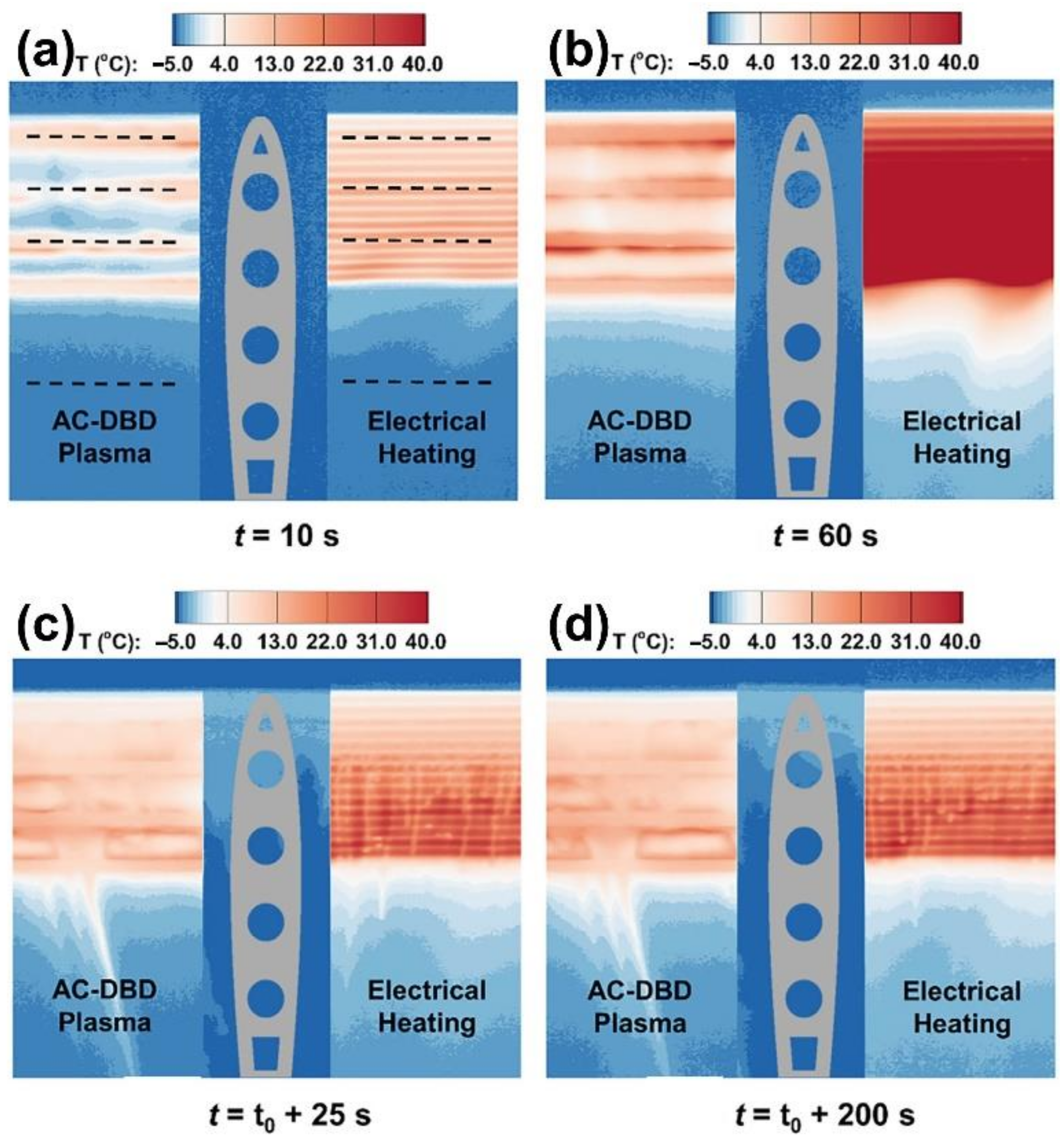
  149. Liu, Y.; Kolbakir, C.; Hu, H.; Hu, H. A comparison study on the thermal effects in DBD plasma actuation and electrical heating for aircraft icing mitigation. Int. J. Heat Mass Transf. 2018, 124, 319–330. [Google Scholar] [CrossRef]
  150. Kriegseis, J.; Möller, B.; Grundmann, S.; Tropea, C. On Performance and Efficiency of Dielectric Barrier Discharge Plasma Actuators for Flow Control Applications. Int. J. Flow Control. 2012, 4, 125–132. [Google Scholar] [CrossRef]
  151. Roth, J.R.; Dai, X.; Rahel, J.; Shermann, D.M. The physics and phenomenology of paraelectric One Atmosphere Uniform Glow Discharge Plasma (OAUGDPTM) actuators for aerodynamic flow control. In Proceedings of the 43rd AIAA Aerospace Sciences Meeting and Exhibit-Meeting Papers, Reno, NV, USA, 10–13 January 2005; pp. 14057–14068. [Google Scholar] [CrossRef]
  152. Roth, J.R.; Rahel, J.; Dai, X.; Sherman, D.M. The physics and phenomenology of One Atmosphere Uniform Glow Discharge Plasma (OAUGDPTM) reactors for surface treatment applications. J. Phys. D Appl. Phys. 2005, 38, 555. [Google Scholar] [CrossRef]
  153. Kraus, J. Electromagnetics, 4th ed.; McGraw-Hill Inc.: New York, NY, USA, 1991. [Google Scholar]
  154. Rodrigues, F.F.; Pascoa, J.C.; Trancossi, M. Analysis of Innovative Plasma Actuator Geometries for Boundary Layer Control. In Proceedings of the ASME 2016 International Mechanical Engineering Congress and Exposition, Phoenix, AZ, USA, 11–17 November 2016. [Google Scholar] [CrossRef]
  155. Enloe, C.L.; McLaughlin, T.E.; VanDyken, R.D.; Kachner, K.D.; Jumper, E.J.; Corke, T.C. Mechanisms and Responses of a Single Dielectric Barrier Plasma Actuator: Plasma Morphology. AIAA J. 2012, 42, 589–594. [Google Scholar] [CrossRef]
  156. Enloe, C.L.; McLaughlin, T.E.; VanDyken, R.D.; Kachner, K.D.; Jumper, E.J.; Corke, T.C.; Post, M.; Haddad, O. Mechanisms and Responses of a Dielectric Barrier Plasma Actuator: Geometric Effects. AIAA J. 2012, 42, 595–604. [Google Scholar] [CrossRef]
  157. Abdollahzadeh, M.; Páscoa, J.C.; Oliveira, P.J. Two-dimensional numerical modeling of interaction of micro-shock wave generated by nanosecond plasma actuators and transonic flow. J. Comput. Appl. Math. 2014, 270, 401–416. [Google Scholar] [CrossRef]
  158. Pons, J.; Moreau, E.; Touchard, G. Asymmetric surface dielectric barrier discharge in air at atmospheric pressure: Electrical properties and induced airflow characteristics. J. Phys. D Appl. Phys. 2005, 38, 3635. [Google Scholar] [CrossRef]
  159. Léger, L.; Moreau, E.; Touchard, G. Electrohydrodynamic airflow control along a flat plate by a DC surface corona discharge-Velocity profile and wall pressure measurements. In Proceedings of the 1st Flow Control Conference, St. Louis, MO, USA, 24–26 June 2002. [Google Scholar] [CrossRef]
  160. Rodrigues, F.F.; Pascoa, J.C.; Trancossi, M. Experimental Analysis of Alternative Dielectric Materials for DBD Plasma Actuators. In Proceedings of the ASME International Mechanical Engineering Congress and Exposition. Proceedings (IMECE), Salt Lake City, UT, USA, 11–14 November 2019. [Google Scholar] [CrossRef]
  161. Dong, B.; Bauchire, J.M.; Pouvesle, J.M.; Magnier, P.; Hong, D. Experimental study of a DBD surface discharge for the active control of subsonic airflow. J. Phys. D Appl. Phys. 2008, 41, 155201. [Google Scholar] [CrossRef]
  162. Jukes, T.N.; Choi, K.S.; Segawa, T.; Yoshida, H. Jet flow induced by a surface plasma actuator. Proc. Inst. Mech. Eng. Part I J. Syst. Control. Eng. 2008, 222, 347–356. [Google Scholar] [CrossRef]
  163. Joussot, R.; Hong, D.; Rabat, H.; Boucinha, V.; Weber-Rozenbaum, R.; Leroy-Chesneau, A. Thermal characterization of a DBD plasma actuator: Dielectric temperature measurements using infrared thermography. In Proceedings of the 40th AIAA Fluid Dynamics Conference, Chicago, IL, USA, 28 June–1 July 2010. [Google Scholar] [CrossRef]
  164. Stanfield, S.A.; Menart, J.; DeJoseph, C.; Kimmel, R.L.; Hayes, J.R. Rotational and Vibrational Temperature Distributions for a Dielectric Barrier Discharge in Air. AIAA J. 2012, 47, 1107–1115. [Google Scholar] [CrossRef]
  165. Tirumala, R.; Benard, N.; Moreau, E.; Fenot, M.; Lalizel, G.; Dorignac, E. Temperature characterization of dielectric barrier discharge actuators: Influence of electrical and geometric parameters. J. Phys. D Appl. Phys. 2014, 47, 255203. [Google Scholar] [CrossRef]
  166. Rodrigues, F.F.; Pascoa, J.C.; Trancossi, M. Experimental Thermal Characterization of DBD Plasma Actuators. In Proceedings of the ASME International Mechanical Engineering Congress and Exposition. Proceedings (IMECE), Pittsburgh, PA, USA, 9–15 November 2018. [Google Scholar] [CrossRef]
  167. Rodrigues, F.F.; Pascoa, J.C.; Trancossi, M. Experimental Analysis of Dielectric Barrier Discharge Plasma Actuators Thermal Characteristics under External Flow Influence. J. Heat Transfer. 2018, 140, 102801. [Google Scholar] [CrossRef]
  168. Abbasi, A.A.; Li, H.; Weiwei, H.; Meng, X. Thermal characteristics of plasma actuators in turbulent boundary layer. In Proceedings of the AIAA AVIATION 2020 FORUM, Virtual Event, 15–19 June 2020. [Google Scholar] [CrossRef]
  169. Kaneko, Y.; Nishida, H.; Tagawa, Y. Visualization of the Electrohydrodynamic and Thermal Effects of AC-DBD Plasma Actuators of Plate- and Wire-Exposed Electrodes. Actuators 2022, 11, 38. [Google Scholar] [CrossRef]
  170. Aberoumand, S.; Jafarimoghaddam, A.; Aberoumand, H. Numerical Investigation on the Impact of DBD Plasma Actuators on Temperature Enhancement in the Channel Flow. Heat Transfer—Asian Res. 2017, 46, 497–510. [Google Scholar] [CrossRef]
  171. Benmoussa, A.; Belasri, A.; Harrache, Z. Numerical investigation of gas heating effect in dielectric barrier discharge for Ne-Xe excilamp. Curr. Appl. Phys. 2017, 17, 479–483. [Google Scholar] [CrossRef]
  172. Zhang, X.; Zhao, Y.; Yang, C. Recent developments in thermal characteristics of surface dielectric barrier discharge plasma actuators driven by sinusoidal high-voltage power. Chin. J. Aeronaut. 2022, 36, 1–21. [Google Scholar] [CrossRef]
  173. Preventing the Dangerous Formation of Ice on Aircraft|PHOBIC2ICE Project|Results in Brief|H2020|CORDIS|European Commission. Available online: https://cordis.europa.eu/article/id/386841-preventing-the-dangerous-formation-of-ice-on-aircraft (accessed on 6 November 2022).
  174. Volpe, A.; Gaudiuso, C.; Ancona, A. Laser Fabrication of Anti-Icing Surfaces: A Review. Materials 2020, 13, 5692. [Google Scholar] [CrossRef]
  175. Alsabagh, A.S.Y.; Tiu, W.; Xu, Y.; Virk, M.S. A Review of the Effects of Ice Accretion on the Structural Behavior of Wind Turbines. Wind. Eng. 2013, 37, 59–70. [Google Scholar] [CrossRef]
  176. Liu, Y.; Kolbakir, C.; Hu, H.; Hu, H. A comparison study on AC-DBD plasma and electrical heating for aircraft icing mitigation. In Proceedings of the AIAA Aerospace Sciences Meeting, Kissimmee, FL, USA, 8–12 January 2018. [Google Scholar] [CrossRef] [Green Version]
  177. Chen, J.; Liang, H.; Wu, Y.; Wei, B.; Zhao, G.; Tian, M.; Xie, L. Experimental Study on Anti-Icing Performance of NS-DBD Plasma Actuator. Appl. Sci. 2018, 8, 1889. [Google Scholar] [CrossRef] [Green Version]
  178. Little, J.; Takashima, K.; Nishihara, M.; Adamovich, I.; Samimy, M. Separation Control with Nanosecond-Pulse-Driven Dielectric Barrier Discharge Plasma Actuators. AIAA J. 2012, 50, 350–365. [Google Scholar] [CrossRef]
  179. Kolbakir, C.; Hu, H.; Liu, Y.; Hu, H. A hybrid anti-/de-icing strategy by combining ns-dbd plasma actuator and superhydrophobic coating for aircraft icing mitigation. In Proceedings of the AIAA Scitech 2019 Forum, San Diego, CA, USA, 7–11 January 2019. [Google Scholar] [CrossRef]
  180. Waldman, R.M.; Li, H.; Guo, H.; Li, L.; Hu, H. An experimental investigation on the effects of surface wettability on water runback and ice accretion over an airfoil surface. In Proceedings of the 8th AIAA Atmospheric and Space Environments Conference, Washington, DC, USA, 13–17 June 2016. [Google Scholar] [CrossRef] [Green Version]
  181. Zheng, X.; Song, H.; Bian, D.; Liang, H.; Zong, H.; Huang, Z.; Wang, Y.; Xu, W. A hybrid plasma de-icing actuator by using SiC hydrophobic coating-based quartz glass as barrier dielectric. J. Phys. D Appl. Phys. 2021, 54, 375202. [Google Scholar] [CrossRef]
  182. Liu, Y.; Kolbakir, C.; Starikovskiy, A.Y.; Miles, R.; Hu, H. An experimental study on the thermal characteristics of NS-DBD plasma actuation and application for aircraft icing mitigation. Plasma Sources Sci. Technol. 2019, 28, 014001. [Google Scholar] [CrossRef] [Green Version]
  183. Liu, Y.; Kolbakir, C.; Hu, H.; Meng, X.; Hu, H. An experimental study on the thermal effects of duty-cycled plasma actuation pertinent to aircraft icing mitigation. Int. J. Heat Mass Transf. 2019, 136, 864–876. [Google Scholar] [CrossRef]
  184. Wei, B.; Wu, Y.; Liang, H.; Chen, J.; Zhao, G.; Tian, M.; Xu, H. Performance and mechanism analysis of nanosecond pulsed surface dielectric barrier discharge based plasma deicer. Phys. Fluids 2019, 31, 091701. [Google Scholar] [CrossRef]
  185. Fang, X.; Su, Z.; Song, H.; Liang, H.; Xie, L.; Liu, X. Parametric Investigation of High-voltage Plasma Discharge for Aircraft Icing Mitigation. In Proceedings of the 2021 IEEE 2nd China International Youth Conference on Electrical Engineering, CIYCEE 2021, Chengdu, China, 15–17 December 2021. [Google Scholar] [CrossRef]
  186. Su, Z.; Liang, H.; Zong, H.; Li, J.; Fang, X.; Wei, B.; Chen, J.; Kong, W. Geometrical and electrical optimization of NS-SDBD streamwise plasma heat knife for aircraft anti-icing. Chin. J. Aeronaut. 2022; in press. [Google Scholar] [CrossRef]
  187. Meng, X.; Hu, H.; Li, C.; Abbasi, A.A.; Cai, J.; Hu, H. Mechanism study of coupled aerodynamic and thermal effects using plasma actuation for anti-icing. Phys. Fluids 2019, 31, 037103. [Google Scholar] [CrossRef] [Green Version]
  188. Kolbakir, C.; Hu, H.; Liu, Y.; Hu, H. An experimental study on different plasma actuator layouts for aircraft icing mitigation. Aerosp. Sci. Technol. 2020, 107, 106325. [Google Scholar] [CrossRef]
  189. Lindner, M.; Pipa, A.V.; Karpen, N.; Hink, R.; Berndt, D.; Foest, R.; Bonaccurso, E.; Weichwald, R.; Friedberger, A.; Caspari, R.; et al. Icing Mitigation by MEMS-Fabricated Surface Dielectric Barrier Discharge. Appl. Sci. 2021, 11, 11106. [Google Scholar] [CrossRef]
  190. Jia, Y.; Liang, H.; Zong, H.; Wei, B.; Xie, L.; Hua, W.; Li, Z. Ice shape modulation with nanosecond pulsed surface dielectric barrier discharge plasma actuator towards flight safety. Aerosp. Sci. Technol. 2022, 120, 107233. [Google Scholar] [CrossRef]
  191. Gao, T.X.; Luo, Z.B.; Zhou, Y.; Yang, S.K. A novel de-icing strategy combining electric-heating with plasma synthetic jet actuator. Proc. Inst. Mech. Eng. Part G J. Aerosp. Eng. 2020, 235, 513–522. [Google Scholar] [CrossRef]
  192. Hu, H.; Meng, X.; Cai, J.; Zhou, W.; Liu, Y.; Hu, H. Optimization of Dielectric Barrier Discharge Plasma Actuators for Icing Control. J. Aircraft 2020, 57, 383–387. [Google Scholar] [CrossRef]
  193. Tanaka, T.; Matsuda, H.; Takahashi, T.; Chiba, T.; Watanabe, N.; Sato, H.; Takeyama, M. Experimental Study on the Snow-fall Flow Control of Backward-Facing Steps Using a High-Durability Designed Plasma Electrode. Actuators 2022, 11, 313. [Google Scholar] [CrossRef]
  194. Lilley, A.J.; Roy, S.; Michels, L.; Roy, S. Performance recovery of plasma actuators in wet conditions. J. Phys. D Appl. Phys. 2022, 55, 155201. [Google Scholar] [CrossRef]
  195. Abdollahzadehsangroudi, M.; Pascoa, J.; Rodrigues, F. System for Ice Detection/Prevention and Flow Control Based on the Impression of Sliding Plasma Actuators with Dielectric Discharge Barrier. U.S. Patent WO2018060830A1, 25 September 2017. [Google Scholar]
  196. Rodrigues, F.F.; Abdollahzadeh, M.; Pascoa, J. Dielectric Barrier Discharge Plasma Actuators for Active Flow Control, Ice Formation Detection and Ice Accumulation Prevention. In Proceedings of the ASME 2020 Fluids Engineering Division Summer Meeting collocated with the ASME 2020 Heat Transfer Summer Conference and the ASME 2020 18th International Conference on Nanochannels, Microchannels, and Minichannels, Virtual, 13–15 June 2020; Volume 2. [Google Scholar] [CrossRef]
  197. Xie, L.; Liang, H.; Zong, H.; Liu, X.; Li, Y. Multipurpose distributed dielectric-barrier-discharge plasma actuation: Icing sensing, anti-icing, and flow control in one. Phys. Fluids 2022, 34, 071701. [Google Scholar] [CrossRef]
Figure 1. Different anti-icing and deicing techniques generally used in ice protection systems.
Actuators 12 00005 g001
Figure 2. Illustration of the operation of an electro-thermal ice protection system (ETIPS) (reproduced from Huang et al. [39] with permission of Elsevier).
Actuators 12 00005 g002
Figure 3. Schematic of the Electro-Mechanical Expulsion Deicing Systems (reproduced from Huang et al. [39] with permissions from Elsevier).
Actuators 12 00005 g003
Figure 4. Combination of superhydrophobic coatings with electrothermal and photothermal properties (reproduced from Zhao et al. [74] with permissions from Elsevier).
Actuators 12 00005 g004
Figure 5. Schematic diagram of the implementation of capacitive ice sensing (reproduced with permission from Madi et al. [89]).
Actuators 12 00005 g005
Figure 6. Schematic of the conventional surface dielectric barrier discharge plasma actuator (reproduced from Rodrigues et al. [98] with permission of Elsevier).
Actuators 12 00005 g006
Figure 7. Power-flow diagram of a dielectric barrier discharge.
Actuators 12 00005 g007
Figure 8. Typical surface temperature field of a dielectric barrier discharge plasma actuator with a dielectric thickness made of Kapton, 1 mm thick, operating at 8 kVpp and 24 kHz: (a) quiescent conditions (b) under external flow influence (reproduced from Rodrigues et al. [167] with permission of Elsevier).
Actuators 12 00005 g008
Figure 9. Spatial temperature variation along the x-axis and y-axis for a plasma actuator made of Kapton, 1 mm thick, operating at different voltage levels and 24 kHz: (a) variation along the x-axis and (b) variation along the y-axis (reproduced from Rodrigues et al. [166]).
Actuators 12 00005 g009
Figure 10. Comparison between active power, total thermal power generated, and power dissipated as dielectric heating in plasma actuators operating at different voltage levels and 24 kHz: (a) actuator made of Kapton with 0.3 mm thickness and (b) actuator made of Kapton with 1.02 mm thickness (reproduced from Rodrigues et al. [98]).
Actuators 12 00005 g010
Figure 11. Multi-actuator configuration (adapted from Cai et al. [29] on with the permission of Springer).
Actuators 12 00005 g011
Figure 12. Anti-icing (ac) and deicing (df) DBD plasma multi-actuator model at V = 15 m/s and T = −10 °C after: (a) t = 0 s, (b) t = 210 s, (c) t = 930 s, (d) t = 0 s, (e) t = 120 s, (f) t = 180 s (adapted from Cai et al. [29] with the permission of Springer).
Actuators 12 00005 g012
Figure 13. (a) Top view and (b) side view of NACA 0012 airfoil model with the DBD plasma actuator and electrical film heater side-by-side on the surface: (a) top view and (b) cross section view (adapted from Liu et al. [149] with the permission of Elsevier).
Actuators 12 00005 g013
Figure 14. Time evolution of the temperature distributions over the DBD plasma actuator and the electrical film heater airfoil surfaces sides after: (a) t = 10 s, (b) t = 60 s, (c) t = t0 + 25 s, and (d) t = t0 + 200 s (adapted from Liu et al. [149] with the permission of Elsevier).
Actuators 12 00005 g014
Figure 15. Heating mechanism of an impinging droplet on a DBD plasma actuator surface (adapted from Liu et al. [149] with the permission of Elsevier).
Actuators 12 00005 g015
Figure 16. (a) Schematic of NACA 0012 airfoil with NS-DBD plasma actuator attached. (b) Side view of the airfoil with the NS-DBD (adapted from Chen et al. [177] under the Creative Commons Attribution License).
Actuators 12 00005 g016
Figure 17. Dynamic anti-icing process of NS-DBD plasma actuator: (a) LV-HF discharge and (b) HV-LF discharge (adapted from Chen et al. [177] under the Creative Commons Attribution License).
Actuators 12 00005 g017
Figure 18. Schematic of the airfoil model used for anti-icing and deicing studies (adapted from Liu et al. (2019) based on [11] with the permission of IOP Publishing).
Actuators 12 00005 g018
Figure 19. Time-evolution of the dynamic ice accretion experiments over the airfoil surface with the NS-DBD plasma actuator being operated at (a) 2 kHz and (b) 6 kHz (adapted from Liu et al. [182] with the permission of IOP Publishing).
Actuators 12 00005 g019
Figure 20. Ice accretion over the airfoil in duty-cycled plasma actuation (left side) versus conventional continuous plasma actuation (right side) (adapted from Liu et al. [183] with the permission of Elsevier).
Actuators 12 00005 g020
Figure 21. Side and top view of the “stream-wise plasma heat knife” (adapted from Wei et al. [119] with the permission of Elsevier).
Actuators 12 00005 g021
Figure 22. Time evolution of the dynamic anti-icing process at (a) T = −5 °C and (b) T = −15 °C (adapted from Wei et al. [119] with the permission of Elsevier).
Actuators 12 00005 g022
Figure 23. Two different configurations of streamwise plasma heat knife mounted at the leading edge of the airfoil from Su et al. [186] (with permission under a Creative Commons license).
Actuators 12 00005 g023
Figure 24. Ice accretion on the airfoil surface after 112 s (adapted from Meng et al. [187] with the permission of AIP Publishing).
Actuators 12 00005 g024
Figure 25. Anti-icing experiments of the three studied materials. Images below depict a magnification of the area marked in green (adapted from Lindner et al. [189] with permission under the Creative Commons Attribution License).
Actuators 12 00005 g025
Figure 26. Time evolution of the deicing process of ice (a,b) and soft ice (c,d) layers (adapted from Abdollahzadeh et al. [111] with permission under Creative Commons license).
Actuators 12 00005 g026
Figure 27. Variation in the plasma actuator electrical properties in the presence of different adjacent medium: (a) Variation in the DBD sensor/actuator charge in the presence of 4 mm, 8 mm, and 15 mm thick ice layer and a 4 mm thick water film. (b) Temporal variation in the DBD sensor/actuator capacitance and charge in the presence of an ice layer (reproduced from Abdollahzadeh et al. [30] with permissions of Elsevier).
Actuators 12 00005 g027
Figure 28. Segmented encapsulated electrode configuration for ice location detection: (a) Schematic of the actuator configuration with three segmented electrodes. (b) Variation of the monitoring voltage at each segmented electrode with the ice cube on the left side (reproduced from Rodrigues et al. [118]).
Actuators 12 00005 g028
Table 1. Summary of the main disadvantages of the different ice sensing techniques.
Drawbacks of Various Conventional Ice Sensing Techniques
Ultrasonic dampingLack of practical application experience; feasibility under practical conditions not proven.
Piezoelectric sensorDegradation of aerodynamic performance of blade surface, associated with significant measurement error.
Resonance frequency measurementAssociated with large measurement error that does not allow accurate determination of ice accumulation. In addition, ice accumulation detection is affected by the shape of the surface and the velocity of the object to which it is applied.
Vibration diaphragmLack of practical application.
Electrical changeAllows only monitoring of icing conditions in the vicinity of the instrument. Monitoring instruments can affect the aerodynamic performance of the rotor blades.
Temperature changeUnable to detect ice formation on the surface of the blades in a timely manner.
Optical measurement technologySignificant deviation between the calculation result and the actual situation, the observation period is limited, the ice accumulation may change the position and shape of the projection aperture, and it is difficult to use during the day. In addition, the installation of the light source may affect the aerodynamic performance of the surface.
Table 2. Summary of the main parameters that influence the DBD plasma actuators performance.
Parameters That Influence the Plasma Actuator Performance
Input signal characteristics➢ Voltage amplitude (1–80 kVpp) [103,104]
➢ Frequency (1–60 kHz) [105,106]
➢ Waveform type (sinusoidal, quadratic, or triangular) [107]
Geometrical parameters➢ Exposed electrode width (1–10 mm) [92,108]
➢ Embedded electrode width (8–20 mm) [109,110]
➢ Gap between the electrodes (0–3 mm) [109]
➢ Dielectric thickness (0.3–4 mm) [110,111]
Dielectric materials➢ Kapton [112]
➢ Teflon [109]
➢ PMMA [110]
➢ PIB rubber [111]
➢ Macor [113]
➢ Cirlex [92]
➢ PVDF [114]
Actuator configuration➢ Single DBD Plasma actuator [115]
➢ Micro DBD Plasma actuator [108]
➢ Nano second pulsed plasma actuator [116]
➢ Multiple encapsulated electrode actuator [112]
➢ Sliding DBD plasma actuator [110]
➢ Stair-shaped DBD plasma actuator [117]
➢ Segmented electrode plasma actuator [118]
➢ Plasma heat knife actuator [119]
➢ Plasma synthetic jet actuator (linear or annular) [120,121]
➢ Curved plasma actuators (horseshoe or serpentine) [122,123]
Table 3. Summary of the possible applications of DBD plasma actuators.
DBD Plasma Actuators’ Applications
Active Flow Control Field➢ Flow separation control [132,133,134]
➢ Wake control [135]
➢ Aircraft noise reduction [136,137]
➢ Modification of velocity fluctuations [138,139,140]
➢ Drag reduction [94]
➢ Lift coefficient enhancement [103,141]
➢ Flow boundary layer modification [142]
➢ Turbulence reduction [143,144]
Heat Transfer Field➢ Film cooling efficiency enhancement [145,146]
➢ Surface cooling [147]
➢ Deicing and anti-icing [28,148,149]
➢ Ice sensing [30,111]
Disclaimer/Publisher’s Note: The statements, opinions and data contained in all publications are solely those of the individual author(s) and contributor(s) and not of MDPI and/or the editor(s). MDPI and/or the editor(s) disclaim responsibility for any injury to people or property resulting from any ideas, methods, instructions or products referred to in the content.

