Seismic Strengthening of the Bagh Durbar Heritage Building in Kathmandu Following the Gorkha Earthquake Sequence


Abstract
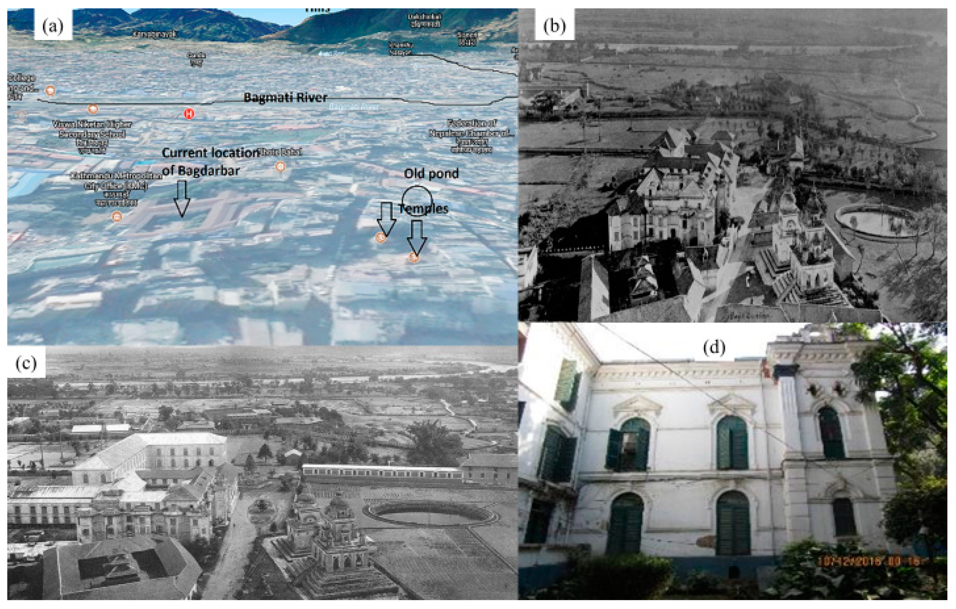
:1. Introduction
2. Materials and Methods
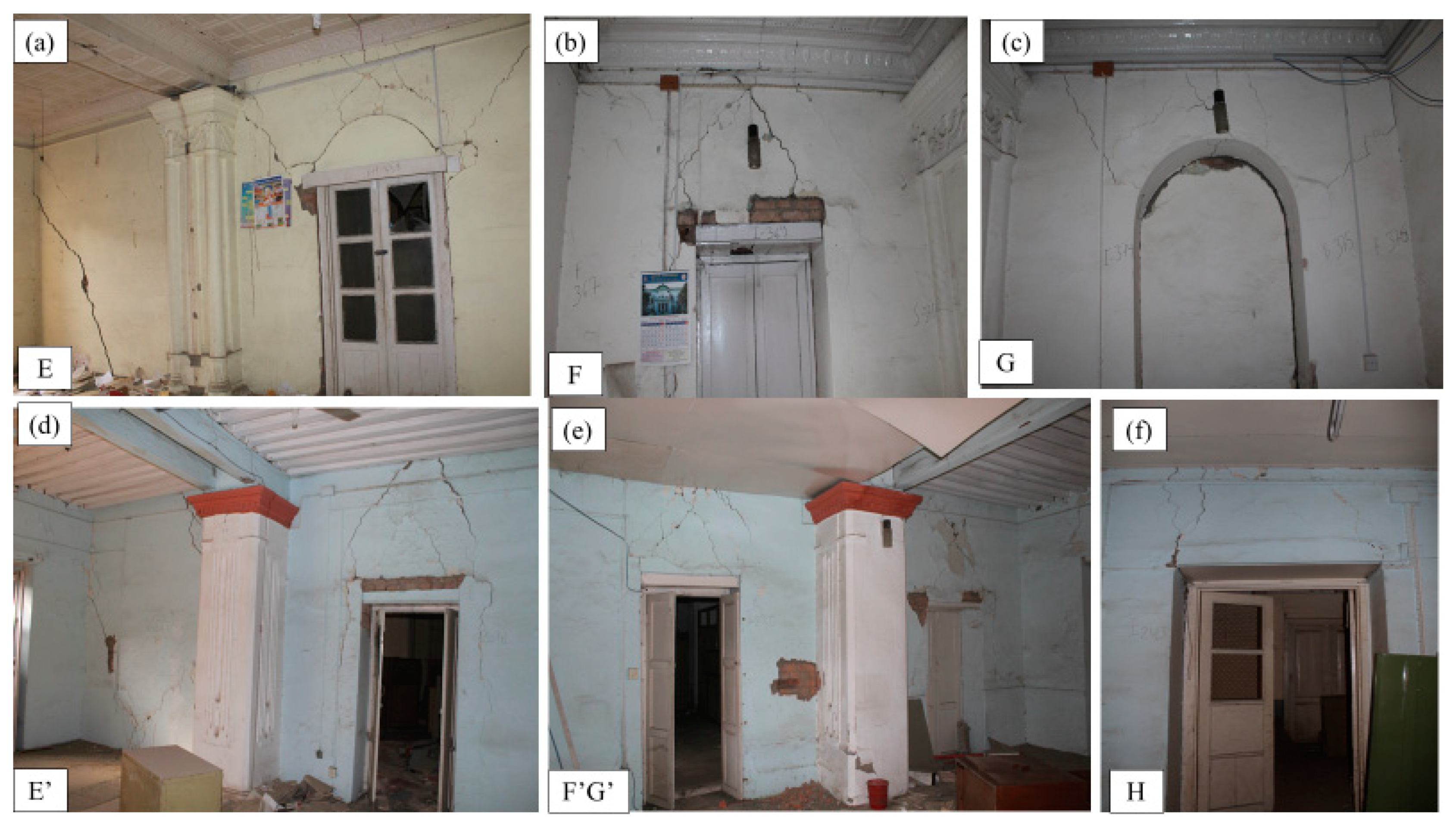
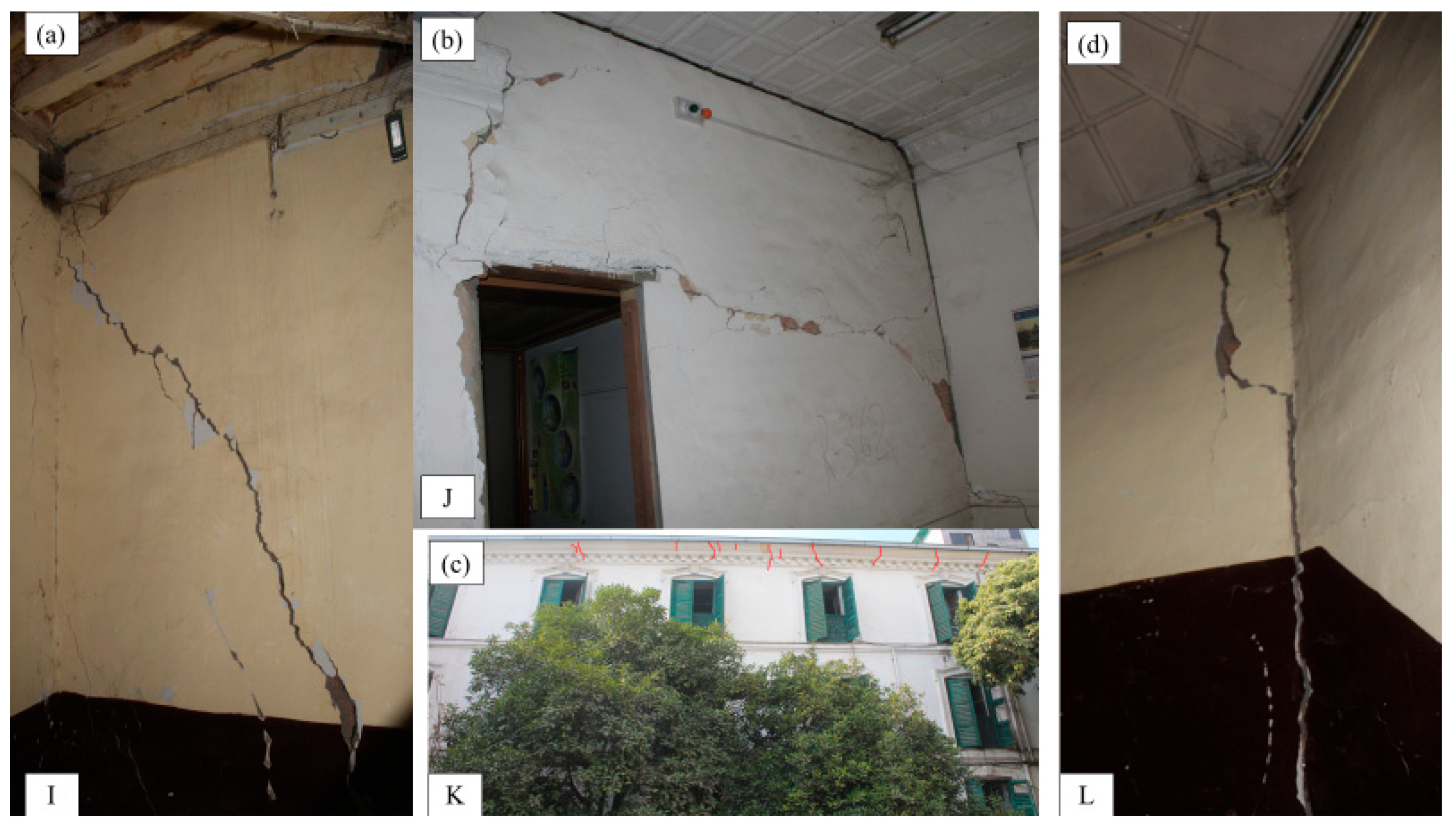
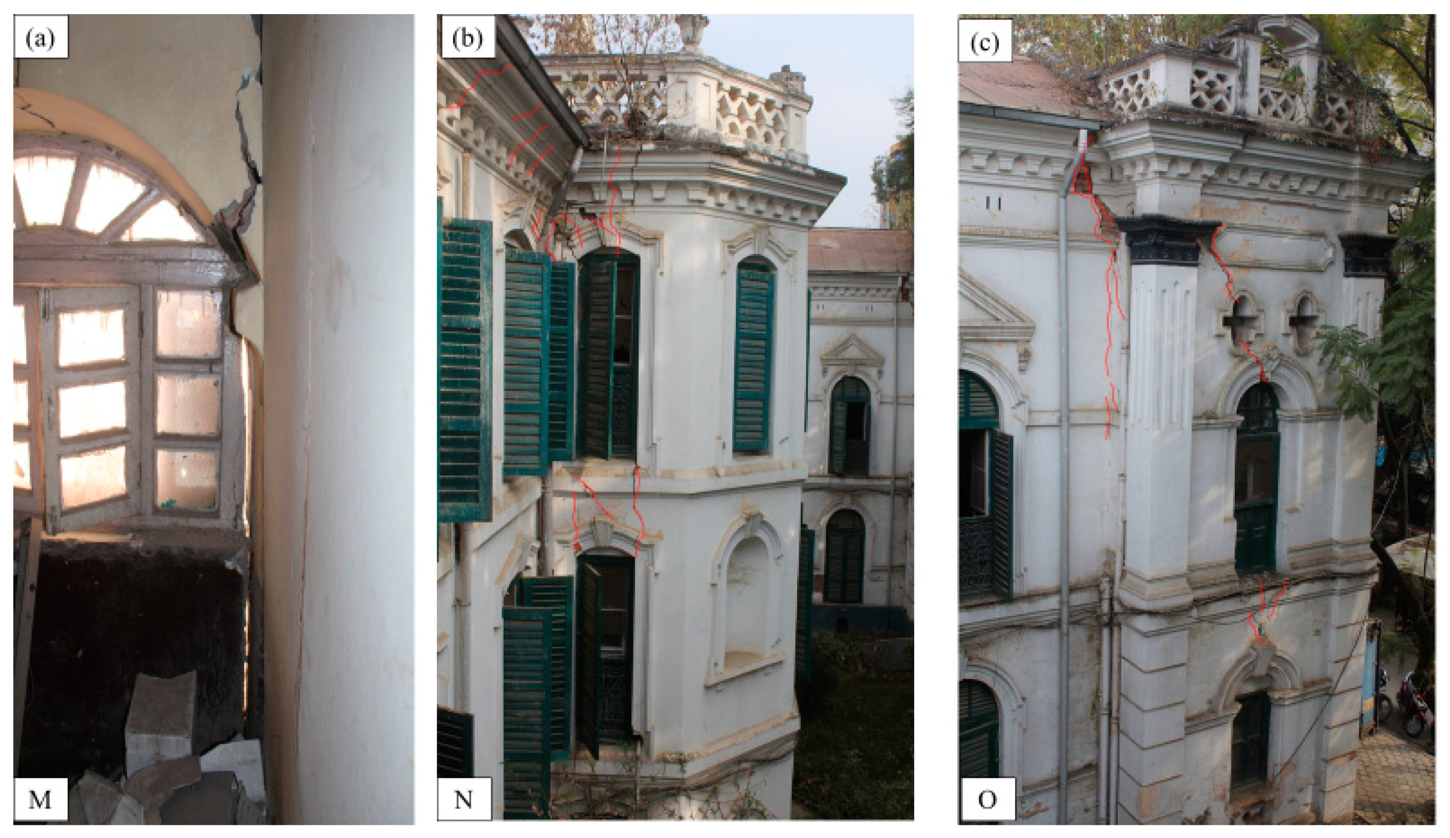
Overview of the Damage
- Irregular building shape in plan (courtyard with wings, unequal bay-width) and room shape (long-rectangular and inclined)
- Story height is more than 3 m, and the building is a three-storied brick in mud-mortar construction
- Outside walls/corridors are relatively long (>10m)
- Lack of vertical reinforcement in the walls, corners, and junctions
- Lack of horizontal bands, corner-stitch, and gable bands in the structure
- Flexible floors with variation in the floor-system and floor levels without effective bracing
3. Structural Assessment
3.1. Qualitative Evaluation
3.2. Material Characterization
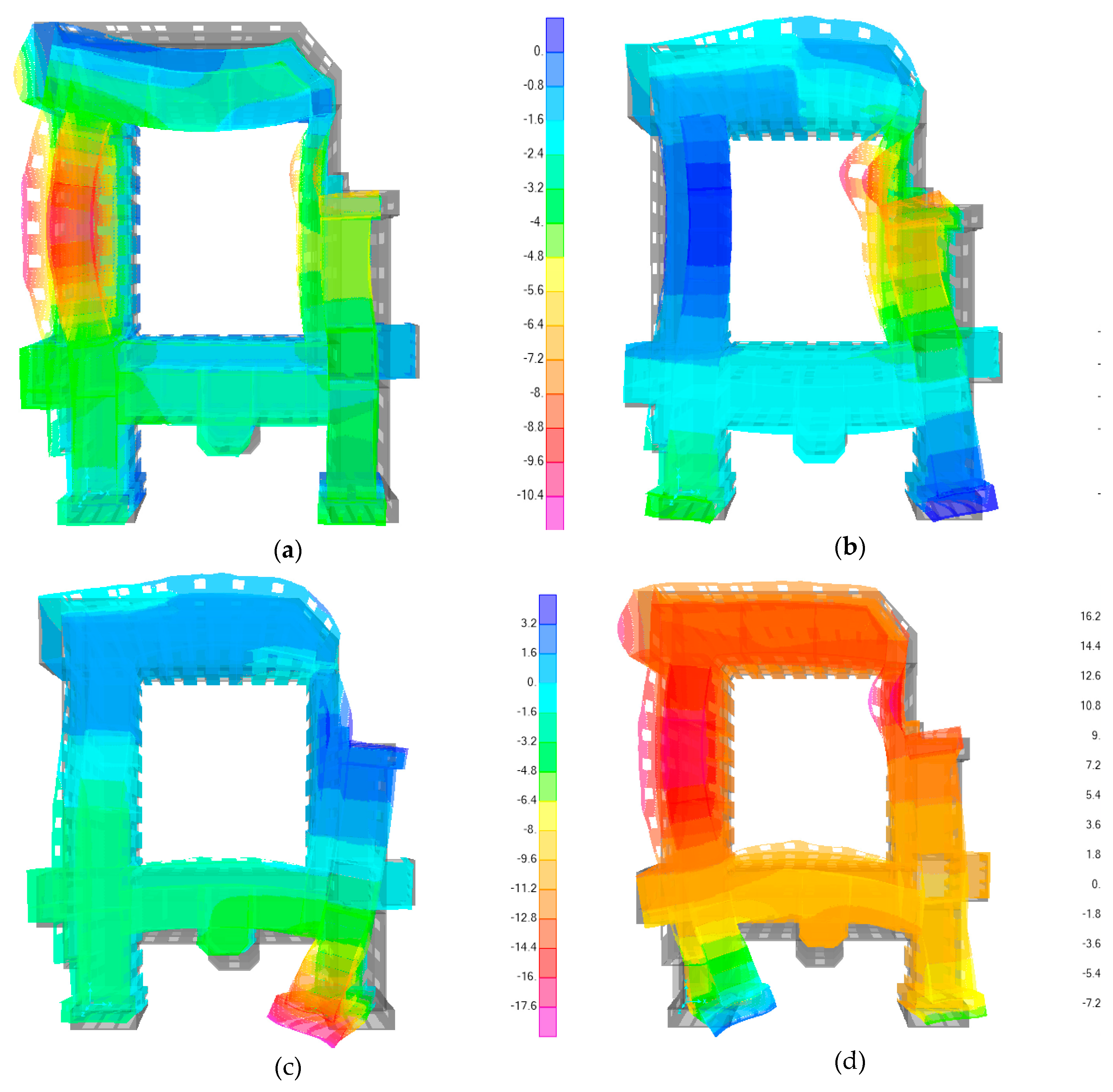
3.3. Analytical Modeling
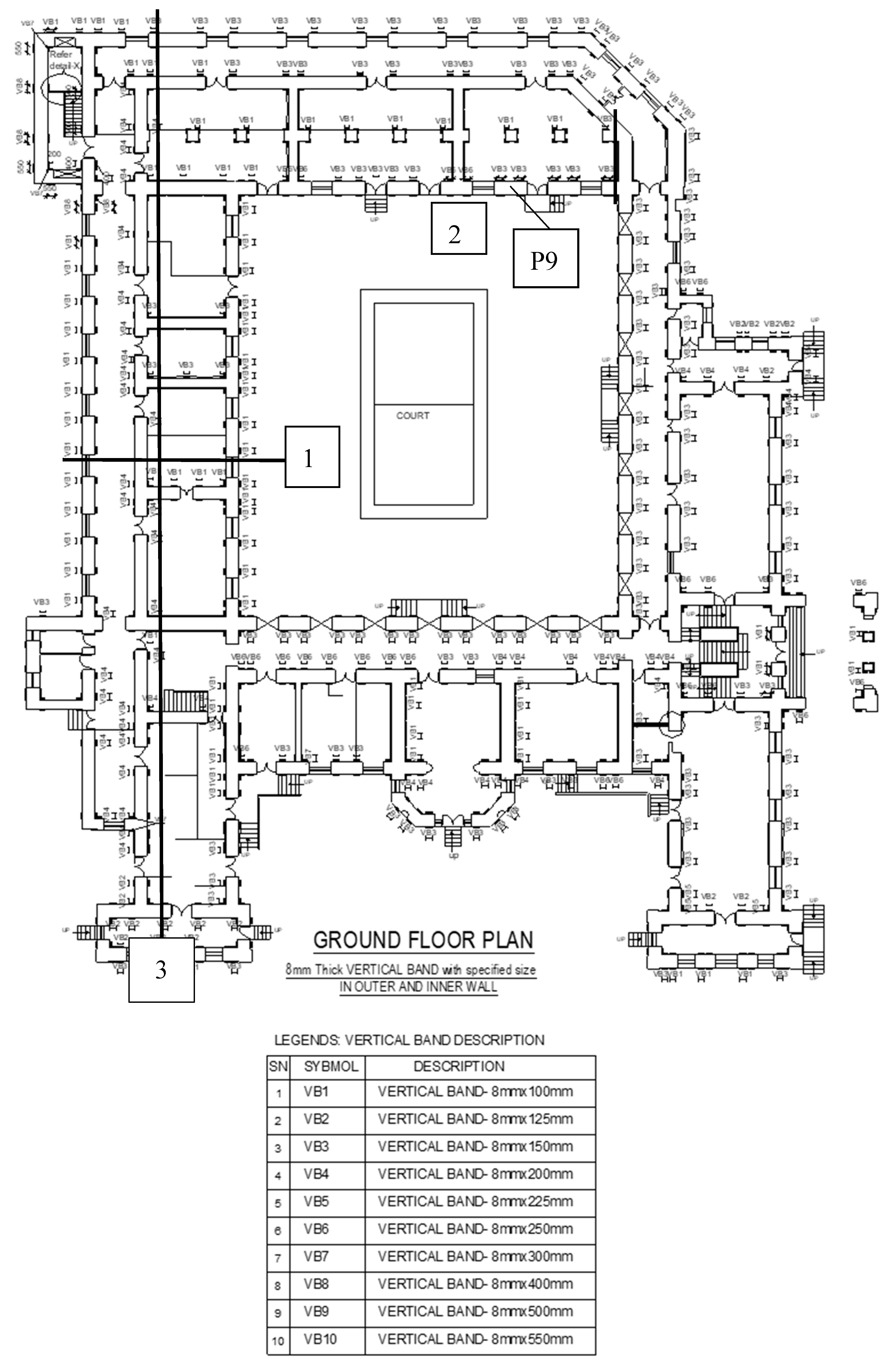
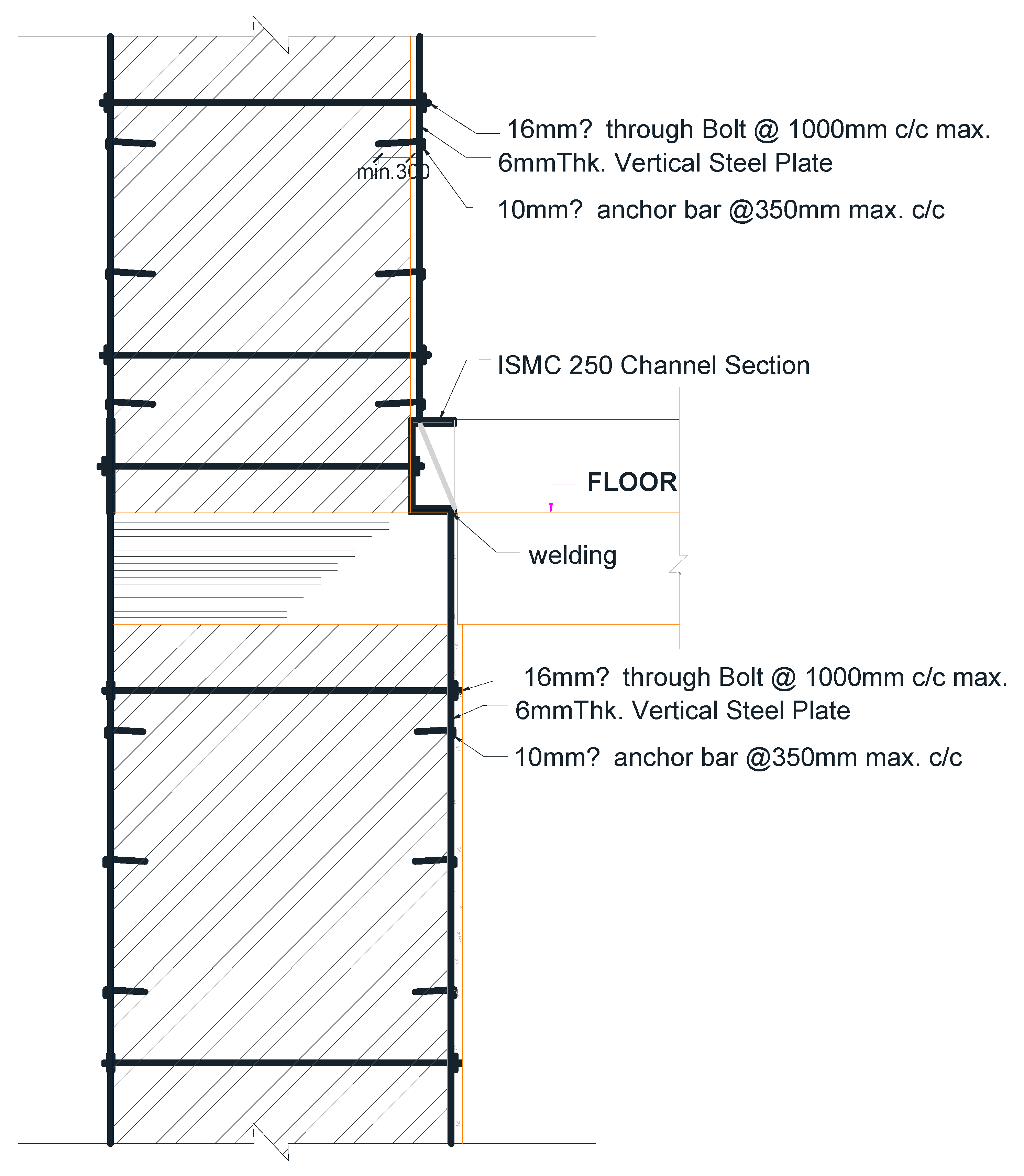
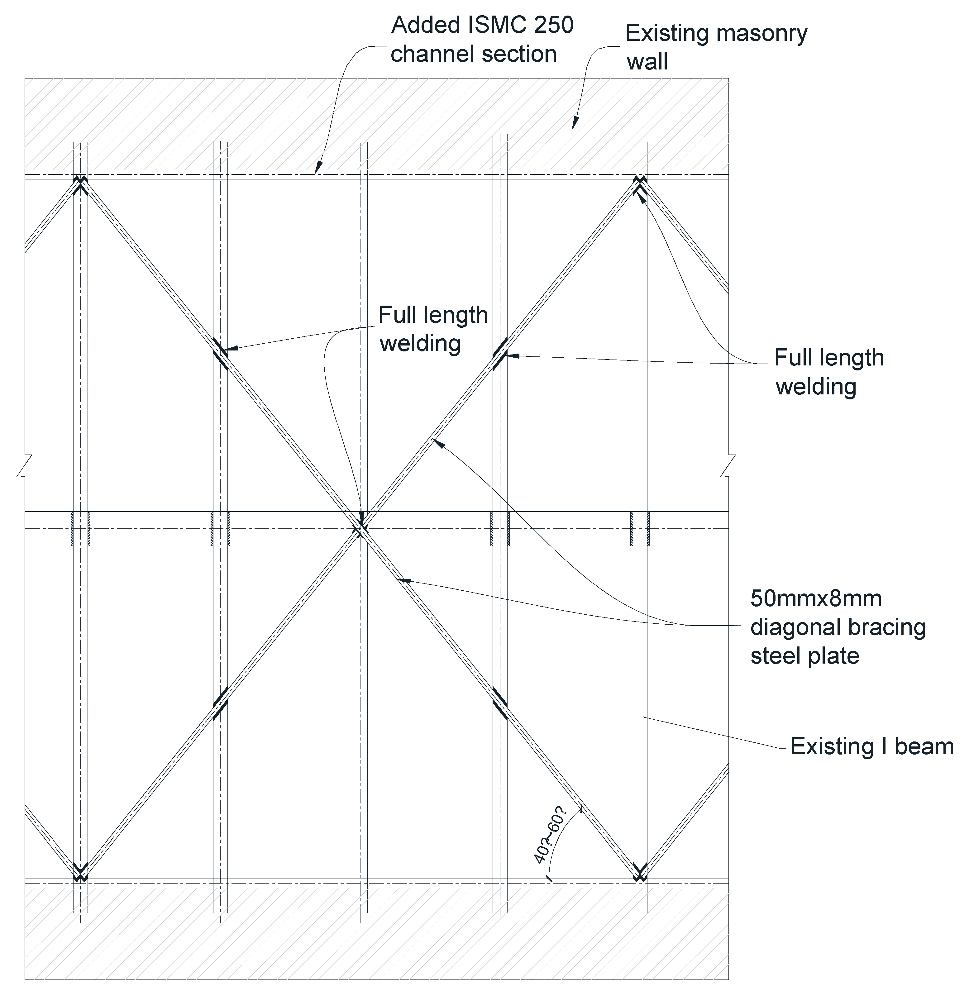
4. Design of Structural Restoration and Seismic Strengthening
5. Conclusions
Author Contributions
Funding
Acknowledgments
Conflicts of Interest
References
- National Planning Commission. Post-Earthquake Damage Assessment; Government of Nepal, National Planning Commission: Kathmandu, Nepal, 2015; Volume A and B.
- Gautam, D.; Fabbrocino, G.; Santucci de Magistris, F. Derive empirical fragility functions for Nepali residential buildings. Eng. Struct. 2018, 171, 617–628. [Google Scholar] [CrossRef]
- Pandit, A.K.; Yadav, R.; Jha, S.K.; Adhikari, R. Seismic vulnerability assessment of masonry buildings in Kathmandu Valley after Gorkha Earthquake 2015: A case study of Administrative Staff College building. In Proceedings of the International Conference on Earthquake Engineering and Post Disaster Reconstruction Planning, Bhaktapur, Nepal, 24–26 April 2016; pp. 244–251. [Google Scholar]
- Langenbach, R. Performance of the earthen Arg-e-Bam (Bam Citadel) during the 2003 Bam, Iran, earthquake. Earthq. Spectra 2005, 21, S345–S374. [Google Scholar] [CrossRef]
- D’Ayala, D.; Benzoni, G. Historic and traditional structures during the 2010 Chile earthquake: Observations, codes, and conservation strategies. Earthq. Spectra 2012, 28, S425–S451. [Google Scholar] [CrossRef]
- Lucibello, G.; Brandonisio, G.; Mele, E.; De Luca, A. Seismic damage and performance of Palazzo Centi after L’Aquila earthquake: A paradigmatic case study of effectiveness of mechanical steel ties. Eng. Fail. Anal. 2013, 34, 407–430. [Google Scholar] [CrossRef]
- Mazzoni, S.; Castori, G.; Galasso, C.; Calvi, P.; Dreyer, R.; Fischer, E.; Fulco, A.; Sorrentino, L.; Wilson, J.; Penna, A.; et al. 2016–17 Central Italy Earthquake Sequence: Seismic retrofit policy and effectiveness. Earthq. Spectra 2018. [Google Scholar] [CrossRef]
- Ferreira, T.M.; Vicente, R.; Mendes da Silva, J.A.R.; Varum, H.; Costa, A. Seismic vulnerability assessment of historical urban center in Seixal, Portugal. Bull. Earthq. Eng. 2013, 11, 1753–1773. [Google Scholar] [CrossRef]
- Vicente, R.; Rodrigues, H.; Varum, H.; Mendes Da Silva, J.A.R. Evaluation of strengthening techniques of traditional masonry buildings: Case study of four-building aggregate. J. Perform. Constr. Facil. 2011, 25, 202–216. [Google Scholar] [CrossRef]
- Lamego, P.; Lourenco, P.B.; Sousa, M.L.; Marques, R. Seismic vulnerability and risk analysis of the old building stock at urban scale: Application to a neighborhood in Lisbon. Bull. Earthq. Eng. 2017, 15, 2901–2937. [Google Scholar] [CrossRef]
- Asteris, P.G.; Chronopoulos, M.P.; Chrysostomou, C.Z.; Varum, H.; Plevris, V.; Kyriakides, N.; Silva, V. Seismic vulnerability assessment of historical masonry structural systems. Eng. Struct. 2014, 62–63, 118–134. [Google Scholar] [CrossRef]
- de Felice, G.; De Santis, S.; Lourenco, P.B.; Mendes, N. Methods and challenges for the seismic assessment of historic masonry structures. Int. J. Archit. Herit. 2017, 11, 143–160. [Google Scholar] [CrossRef]
- Casapulla, C.; Maione, A.; Argiento, L.C. Seismic analysis of an existing masonry building according to the multi-level approach of the Italian guidelines on cultural heritage. Ingegneria Sismica 2017, 34, 40–59. [Google Scholar]
- Clementi, F.; Gazzani, V.; Poiani, M.; Mezzapelle, P.A.; Lenci, S. Seismic assessment of a monumental building through nonlinear analyses of a 3D solid model. J. Earthq. Eng. 2018, 22, 35–61. [Google Scholar] [CrossRef]
- Lagomarsino, S.; Cattari, S. PERPETUATE guidelines for seismic performance-based assessment of cultural heritage masonry structures. Bull. Earthq. Eng. 2015, 13, 13–47. [Google Scholar] [CrossRef]
- Milani, G.; Venturini, G. Safety assessment of four masonry churches by a plate and shell FE nonlinear approach. J. Perform. Constr. Facil. 2013, 27, 27–42. [Google Scholar] [CrossRef]
- Rossi, M.; Cattari, S.; Lagomarsino, S. Performance-based assessment of the great mosque of Algiers. Bull. Earthq. Eng. 2015, 13, 369–388. [Google Scholar] [CrossRef]
- Marra, A.; Brigante, D.; Rainieri, C.; Fabbrocino, G. Structural characterization and performance assessment of the Villa d’Este Palace in Tivoli. In Proceedings of the 16th International Brick and Block Masonry Conference “Masonry in a world of challenges”, Padua, Italy, 26–30 June 2016. [Google Scholar]
- Fabbrocino, G.; Marra, A.; Savorra, M.; Fabbrocino, S.; Santucci de Magistris, F.; Rainieri, C.; Brigante, D.; Celiento, A. Increasing the resilience of cultural heritage to earthquakes by knowledge enhancement: The lesson of the Carthusian Monastery in Trisulti. In Resilienza Delle città D’arte ai Terremoti; Atti Dei Convegni Lincei; Accademia Nazionale dei Lincei: Roma, Italy, 2016; Volume 306, pp. 553–566. [Google Scholar]
- Sonda, D.; Miyamoto, K.; Kast, S.; Khanal, A. The restoration and seismic strengthening of the earthquake-damaged UNESCO heritage palace in Kathmandu. Int. J. Archit. Herit. 2018. [Google Scholar] [CrossRef]
- Gautam, D. Seismic performance of world heritage sites in Kathmandu valley during Gorkha seismic sequence of April-May 2015. J. Perform. Constr. Facil. 2017. [Google Scholar] [CrossRef]
- DUDBC (Department of Urban Development and Building Construction). Seismic Vulnerability Evaluation of Guideline for Private and Public Buildings; Government of Nepal, Department of Urban Development and Building Construction: Kathmandu, Nepal, 2011.
- Grunthal, G. European Macroseismic Scale 1988 (EMS-1988); Centre Européen de Géodynamique et de Séismologie: Luxemburg, 1998. [Google Scholar]
- NBC (Nepal Building Code). Seismic Design of Buildings in Nepal (NBC-105); Government of Nepal, Department of Urban Development and Building Construction: Kathmandu, NBC, Nepal, 1994.
- Recommendations PCM. Guidelines for the Assessment and the Mitigation of Seismic Risk of Cultural Heritage with Reference to Italian NTC2008; Directive of the Prime Minister: Rome, Italy, 2011. (In Italian) [Google Scholar]
- FEMA (Federal Emergency Management Agency). NEHRP Guidelines for Seismic Rehabilitation of Buildings; Federal Emergency Management Agency Report (FEMA-273); FEMA: Washington, DC, USA, 1997.
- Rainieri, C.; Fabbrocino, G.; Verderame, G.M. Non-destructive characterization and dynamic identification of a modern heritage building for serviceability seismic analyses. NDT E Int. 2013, 60, 17–31. [Google Scholar] [CrossRef]
- Rainieri, C.; Fabbrocino, G. Development and validation of an automated operational modal analysis algorithm for vibration-based monitoring and tensile load estimation. Mech. Syst. Signal Process. 2015, 60–61, 512–534. [Google Scholar] [CrossRef]
- Rainieri, C.; Marra, A.; Rainieri, G.M.; Gargaro, D.; Pepe, M.; Fabbrocino, G. Integrated non-destructive assessment of relevant structural elements of an Italian heritage site: The Carthusian monastery of Trisulti. J. Phys. Conf. Ser. 2015, 628, 012018. [Google Scholar] [CrossRef]
- CSI (Computer and Structure Inc). SAP: Integrated Software for Structural Analysis and Design; v. 20; CSI: Walnut Creek, CA, USA, 2000. [Google Scholar]
- Bureau of Indian Standards (BIS). Indian Standard Criteria for Earthquake Resistant Design of Structures: Part 1 General Provisions and Buildings (Fifth Revision); IS 456 (Part 1); BIS: New Delhi, India, 2016.
- Bureau of Indian Standards (BIS). Indian Standard Code of Practice for Structural Use of Unreinforced Masonry; Bureau of Indian Standard: New Delhi, India, 1987.


| Parameter | Test Results | Remarks |
|---|---|---|
| Shear strength of masonry wall | 0.1 MPa, 0.1 MPa, and 0.08 MPa for ground floor (GF), first floor (FF), and second floor (SF) | Two tests were carried out on each floor and the average value was taken. Due to lesser dead load, the value was low at the top floor, while because of slight damp conditions, the value did not increase on ground floor. |
| Compressive strength of brick | 6.63 MPa, 1.14 MPa and 5.3 MPa for three units | There was restriction in obtaining more samples, thus, 3.5 MPa bricks were considered to match the categorization. |
| Compressive strength of mortar | Varied from 0.1 MPa to 0.32 MPa in 11 locations | Though not accurate, a penetrometer test was conducted that gave an average strength of 0.18 MPa. |
| Wall core and bonding type | All walls were solid English bond was found | All walls were identified to be solid brick walls as observed at the test and damage locations. |
| Foundation | Masonry strip footing with base width of 1700 mm | Excavation was done in two locations. Stepping was found to be done to increase the width of footing at the base, increasing 50 mm in width at each side at every 150-mm depth. |
| Mode | Period (sec) | Modal Mass Participation Ratio in x-direction | Modal Mass Participation Ratio in y-direction |
|---|---|---|---|
| 1 | 0.295 | 0.450 | 0.071 |
| 2 | 0.292 | 0.054 | 0.046 |
| 3 | 0.276 | 0.087 | 0.170 |
| 4 | 0.272 | 0.000 | 0.190 |
| 5 | 0.249 | 0.025 | 0.038 |
| 6 | 0.242 | 0.014 | 0.051 |
| 7 | 0.228 | 0.001 | 0.060 |
| 8 | 0.222 | 0.008 | 0.001 |
| 9 | 0.200 | 0.050 | 0.006 |
| 10 | 0.199 | 0.002 | 0.001 |
| 11 | 0.198 | 0.001 | 0.007 |
| 12 | 0.198 | 0.000 | 0.060 |
| 13 | 0.187 | 0.011 | 0.015 |
| 14 | 0.181 | 0.011 | 0.007 |
| 15 | 0.167 | 0.001 | 0.008 |
© 2019 by the authors. Licensee MDPI, Basel, Switzerland. This article is an open access article distributed under the terms and conditions of the Creative Commons Attribution (CC BY) license (http://creativecommons.org/licenses/by/4.0/).
Share and Cite
Adhikari, R.; Jha, P.; Gautam, D.; Fabbrocino, G. Seismic Strengthening of the Bagh Durbar Heritage Building in Kathmandu Following the Gorkha Earthquake Sequence. Buildings 2019, 9, 128. https://doi.org/10.3390/buildings9050128
Adhikari R, Jha P, Gautam D, Fabbrocino G. Seismic Strengthening of the Bagh Durbar Heritage Building in Kathmandu Following the Gorkha Earthquake Sequence. Buildings. 2019; 9(5):128. https://doi.org/10.3390/buildings9050128
Chicago/Turabian StyleAdhikari, Rabindra, Pratyush Jha, Dipendra Gautam, and Giovanni Fabbrocino. 2019. "Seismic Strengthening of the Bagh Durbar Heritage Building in Kathmandu Following the Gorkha Earthquake Sequence" Buildings 9, no. 5: 128. https://doi.org/10.3390/buildings9050128