1. Introduction
Motivation for this work is the fact that masonry shell structures as a part of historical buildings such as churches, monasteries and castles are present in a relatively large number not just in Slovenia but also worldwide. Over the years, due to various reasons (change in magnitude and distribution of loading, earthquake loading, foundation settlements, etc.) these structures can be damaged. Consequently, inner forces are redistributed and in many cases the static system is changed. Nevertheless, most of these structures maintain their function also afterwards [
1].
In the case of reconstruction, the load bearing capacity of the shell structure should be checked in accordance with current regulations and, if necessary, appropriate measures have to be undertaken. In this paper, computational analysis of the actual shell structure is demonstrated. By using the results of this analysis, causes for damage are identified and possible rehabilitation and consolidation measures are proposed.
2. Stresses and Typical Damage Patterns of Masonry Shells
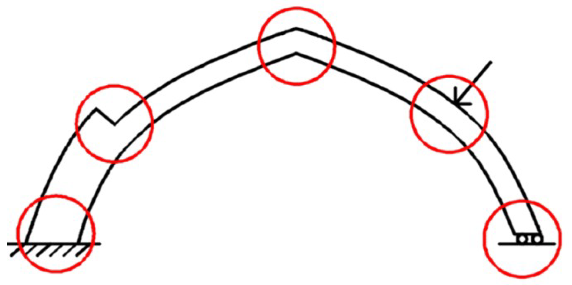
To describe the geometry of the shell, the spatial position of the midsurface and the thickness of the shell at each point have to be known. The analysis of shell structures is usually performed using two theories: Membrane theory, which is usually valid for lager part of the shell and bending theory, which includes the effect of bending [
2]. In areas where due to local disturbances (supports, point loads, changes of curvature or thickness) the ideal membrane stress state is no longer valid (
Figure 1), the membrane theory should be supplemented by the bending theory.
For shell structures in historical buildings in most cases the membrane theory has to be supplemented by the bending theory. As the result of the simultaneous effect of membrane forces
Nx,
Ny, Nxy and bending moments
Mx,
My, Mxy the stresses which occur in the shell can be written as:
The first terms in the above expressions represent the membrane stress while the second terms, the bending stress. The distribution of stresses σx, σy and τxy within the shell thickness is linear. Perpendicular shear stresses τxz in τyz as a consequence of shear forces have a parabolic distribution, but their values are generally small in comparison with other stress components and can usually be neglected.
Damage of shells, often in the form of cracks, occurs due to various reasons: Foundation settlement, horizontal displacements of supporting walls, material deficiencies and degradation or local overloading as well as their combinations. Some typical crack configurations due to various reasons in the case of barrel vault are shown in
Figure 2.
3. Analysis of Masonry Shell in St. Jacobs Church
3.1. Characteristics of the 2004 Earthquake
Generally, Slovenia is a territory with almost regular (moderate) seismic activities. On an average day, an earthquake with a magnitude higher than 1 is normally detected. Further, Dolenja Trebuša lies in a region with some more than average seismic activities. Nevertheless, although this area is not one of the most seismically exposed parts of our country; it still lies quite close to the region, which was severely damaged by the 1976 earthquake (with the magnitude of 6.5 the strongest earthquake that has been recorded in Slovenia so far). The considered 2004 earthquake occurred on 12 July 2004 with an epicenter to the northwest of Dolenja Trebuša (areal distance was about 35 km). It occurred on the same place of the 1998 earthquake (which had the magnitude of 5.7). Both these earthquakes are listed among the three last severe earthquakes that were recorded in Slovenia. Although most of the damage resulting from the 2004 earthquake occurred in the vicinity of Bovec mainly due to local geological conditions, other areas such as Dolenja Trebuša were also affected. The 2004 earthquake caused material damage primarily on older buildings, which in this region have a very low earthquake resistance. Namely, the building stock consists mainly of old stone masonry houses with one or two storeys built largely from two-leaf masonry with two-leaf stone masonry with weak lime mortar and wooden floors [
5].
3.2. Structural Characteristics and Damage of Analyzed Masonry Shell
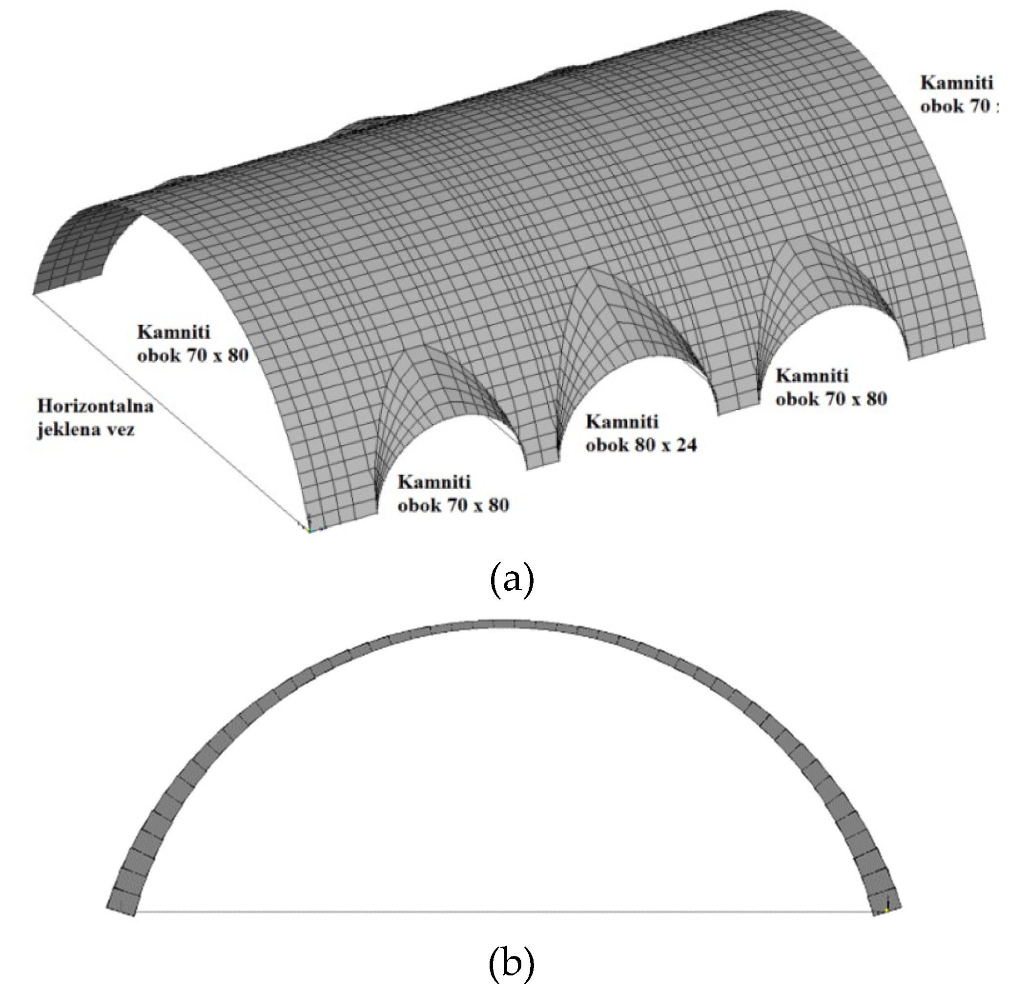
For the analysis, a barrel vault in St. Jacob Church in Dolenja Trebuša in Slovenia was chosen. The Church was built in 1786 and retrofitted in 2013 in order to simultaneously rehabilitate and strengthen its structure after the earthquake in 2004. In spite of the renovation in 2013, cracks in the considered vault reopened. The stone masonry barrel vault is built out of limestone and leech stone in lime mortar. Geometry and materials of the vault are shown in
Figure 3. The length of the vault is 10 m (above the nave) with a span of 7.75 m. The thickness of the vault is changing from 30 cm at the base and to 8 cm at the top.
Before rehabilitation and strengthening of the church in 2013, numerous cracks in the walls and vaults were listed. In the middle area of the analysed vault there was a crack running along the entire length of the nave, which continued through the supporting arch and presbytery vault with length of 13.5 m and thickness of 1.0 mm. Other cracks were also present on the vaults, especially in the area of the transverse vaults although of smaller width and length (
Figure 4).
The cracks although to a lesser extent, reopened in the same places after the repair works in 2013 (
Figure 5).
3.3. Static Analysis of Masonry Shell
The stone masonry barrel vault was analysed by using the SAP2000 software [
7]. A combination of three and four-node shell finite elements combined with linear finite elements was used in the model. The structure was modelled with varying thickness according to actual geometry. Supports (main arch, closed arches at the side, supporting wall) were modelled using linear finite elements of the corresponding cross section. The barrel vault was modelled with 2211 shell and 436 linear finite elements interconnected in 2499 nodes. Horizontal steel ties were modelled as linear elements with circular cross section of ϕ 32–45 mm (
Figure 6).
When the registered crack pattern is compared with possible crack configurations shown in
Figure 2, several actions can be identified as the potential cause of such damage. The longitudinal crack at the bottom middle part of the shell may thus be caused either by simultaneous horizontal divergent displacement of supporting walls (
Figure 2 top left), differential settlement of foundations (
Figure 2 bottom left) or point load in the central part of the shell (
Figure 2 bottom right).
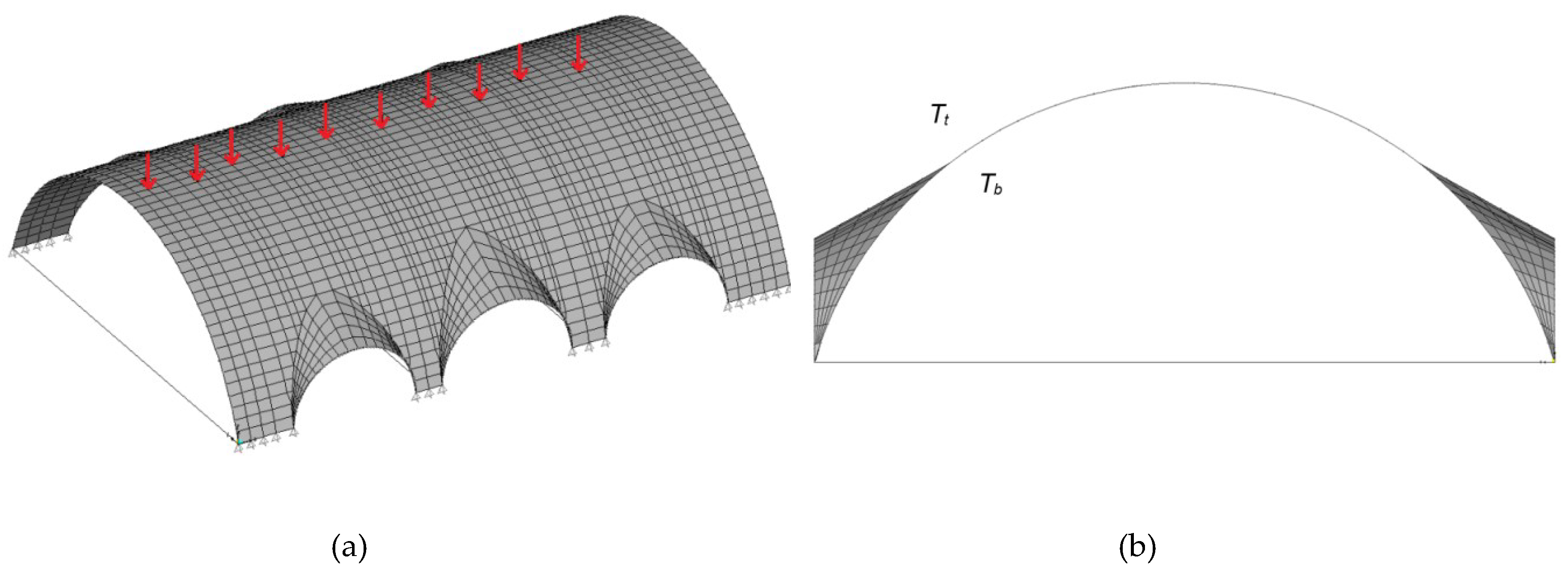
Since the increase of the structures weight was eliminated as a possible cause for the registered crack pattern, other possible causes were analysed in the numerical analysis: Self weight of structure and rubble layer, differential settlement of foundations, seismic loading, maintenance loading and temperature difference (
Figure 7 and
Figure 8).
The implementation of non-linear behaviour would be the most appropriate approach for the analysis of the considered shell. However, we were not involved in any material properties acquisition (all the mechanical parameters were taken from the Technical Report, [
6]) for the analysed shell. Furthermore, our analyses were not part of any official study, and were thus not financially supported. Therefore, the decision was met to perform only linear elastic analyses, which nevertheless provided satisfactory results and enabled the identification of possible causes for the damage.
Five load combinations were considered altogether:
Load case »1«: Self weight and rubble layer:
Load case »2«: Self weight, rubble layer, vertical displacement of outer supports on one side by
Δz = −0.5 cm:
Load case »3«: Self weight, rubble layer, maintenance team:
Load case »4«: Self weight, rubble layer, horizontal displacement of all supports on one side by
Δy = 0.5 cm:
Load case »5«: Self weight, rubble layer, temperature difference:
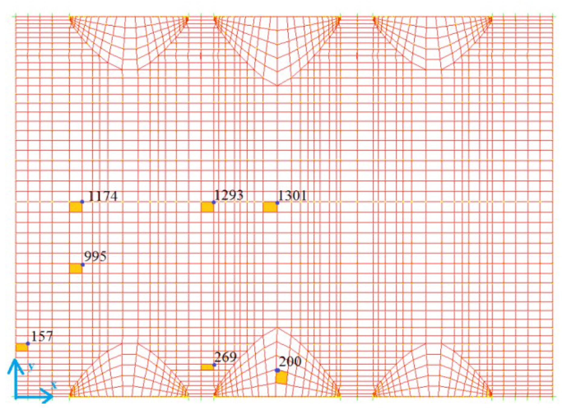
The discrete results’ values are presented for seven points visible in
Figure 9.
The distribution of stresses across the shell thickness is linear. In the evaluation of results, values obtained in the upper (external) and bottom part of the shell were considered. By taking into account the values of z = t/2 and z = −t/2 for the upper and bottom part of the shell, respectively we obtain:
where designations
»up« in »
bot« stand for stresses on the upper and bottom part of the shell. According to Eurocode 6 for masonry structures, the actual compressive stress (
σc) and tensile stress (
σt) should be smaller than the design compressive (
fcd) and/or design tensile strength (
ftd) of the material, respectively. Values of the characteristic compressive (
fc) and tensile strength (
ft) were taken from the Technical Report, reference No. 6 and were obtained from investigations of similarly built stone masonry walls and vaults studied both in situ and in the laboratory of ZRMK. Design values are obtained by dividing the characteristic compressive (
fc) and tensile strength (
ft) of the material with the material safety factor
γM, as given by the code:
The material safety factor
γM is assessed as
γM = 2.0. Calculated stresses should be smaller than permissible values. In the case of tension we obtain:
And in the case of compression:
The results obtained in selected points are summarised in
Table 1.
4. Discussion of the Results
As already stated, five load combinations were considered in order to find the most probable cause for the formation of the registered crack pattern.
In load case »1« self weight and rubble layer was considered. Numerical results show that stresses are locally exceeded in areas where no actual damage was registered on the shell. On the other hand, calculated stresses in areas with cracks are within the permissible limits. However, it should be noted, that the cracks on the upper side of the shell are poorly visible due to the rubble layer and rough surface.
In load case »2« vertical displacement (Δ
z = −0.5 cm) of outer supports on one side was considered which simulates differential settlement of foundations. In this case, high tensile stresses occur in the top area of the shell (
Figure 11), which may cause the recorded longitudinal crack. Differential settlement of foundations can thus be one of possible causes for the registered crack pattern. However, the results of this load case otherwise show high stress levels also in other parts where no damage of the actual shell has been recorded.
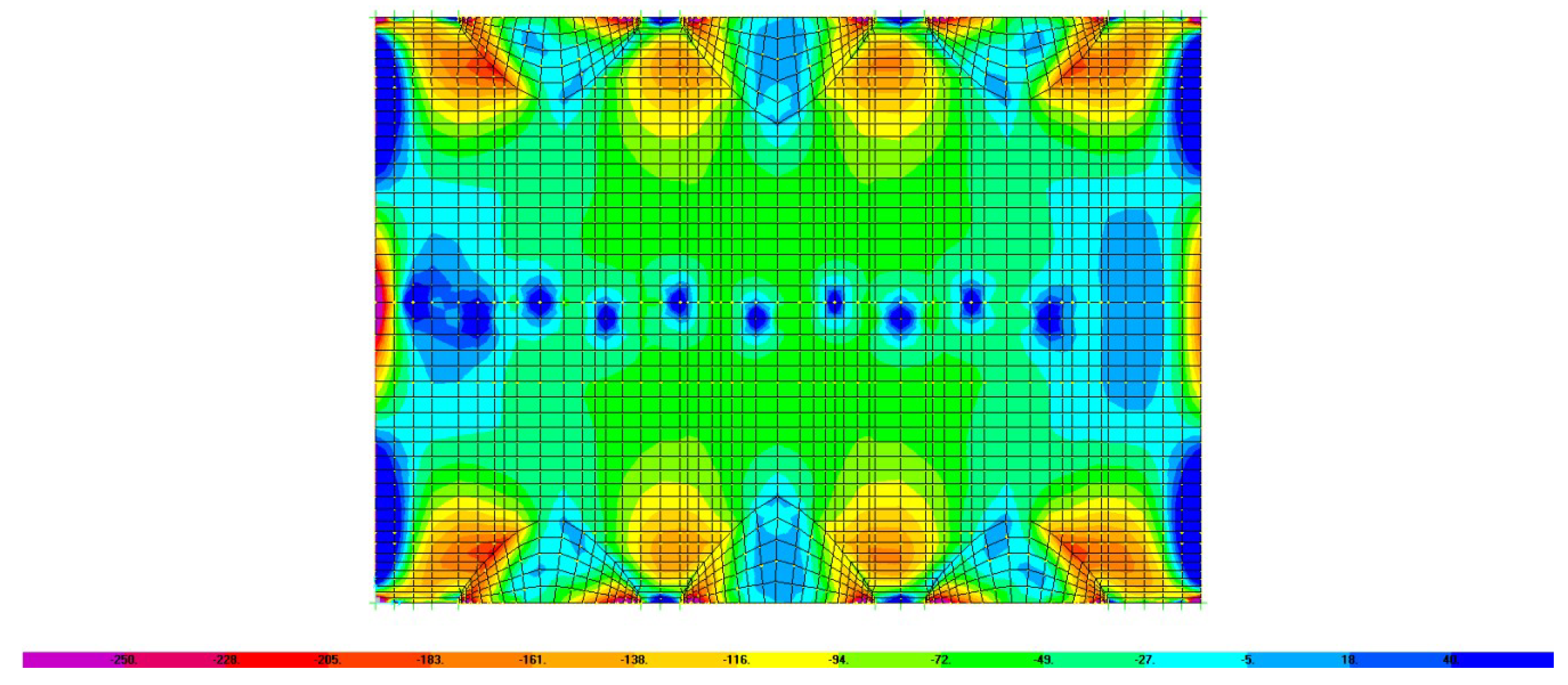
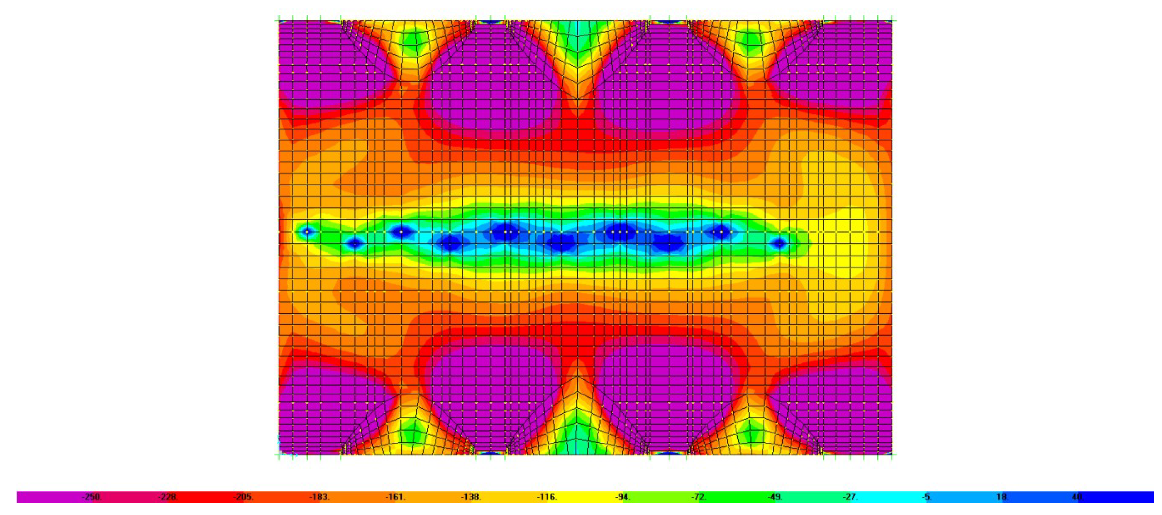
Load case “3” took into account the self weight of the structure, weight of the rubble layer and weight of the maintenance team. In this case, compressive stresses in the upper middle part (
Figure 13) as well as tensile stresses in the lower middle part (
Figure 12) of the analysed shell are exceeded, which coincides with the registered crack pattern. This loading combination can therefore be considered as the most possible cause for the formation of a longitudinal crack [
8].
With load case “4” the impact of seismic loading on the analysed structure was examined. Results show that stresses in this case are not exceeded, and, consequently, the influence of the seismic load as a possible cause for the formation of longitudinal crack can be excluded.
Results of load case “5” which took into account self weight of the structure, rubble layer and temperature change (ΔT = 15 °C) show that such loading combination is critical for collateral vaults but cannot be responsible for the registered longitudinal crack.
The executed numerical analyses thus show that load cases “2” and “3” are the most likely ones to cause the registered crack pattern. The longitudinal crack in the middle area of the analysed shell most likely formed due to separated or combined effect of maintenance team loading and differential settlement of foundations.
5. Possible Repair and Strengthening Measures
Based on the results of the analysis of the considered shell, it can be concluded that the cracks formed mainly due to direct loading of the middle upper part of the shell (simulation of maintenance works in load case “3”). Considering the fact that cracks reappeared in the same areas after repair works in 2013, it is recommended that monitoring of the shell be carried out with an emphasis on the longitudinal crack in the middle part of the shell. In the case that the widening of that crack continues, strengthening of the shell will be required. Strengthening could be done by applying reinforced concrete layer either using FRP (fiber reinforced polymer) or FRM (fiber reinforced mortar) on the critical area. However, if the monitoring does not confirm any propagation (widening and/or length extension) of cracks, strengthening considering unchanged loading condition is not necessary. Nevertheless, the problem in the case of loading of the shell during maintenance works should be solved for any potential future works as the numerical simulations show that the shell is locally overloaded even by weight of a single maintenance worker. A possible simple solution for this problem is a working platform not only for access of the maintenance team but generally also for any secure access to the area above the shell [
8]. The weight of the platform could be partially carried by the existing wooden roof structure and mainly by the stronger stone-masonry walls of the church structure.
6. Conclusions
The paper demonstrates the simulation modelling as a powerful tool in addressing problems of structures’ reconstructions. Although the implementation of non-linear behaviour would be the most appropriate or rather more common approach for the analysis of the considered shell, the analyses carried out in this work showed that it is possible to identify the causes for damage, even with the simple elastic material model, without performing more complex non-linear analyses. As found, the longitudinal crack in the middle area of the analysed shell most likely formed due to the separate or combined effect of maintenance team loading and differential settlement of foundations. However, none of these two most probable causes for the registered crack pattern were considered in the numerical analysis within the official rehabilitation project. Consequently, the main longitudinal crack re-opened after more or less cosmetic patching as a part of rehabilitation works. This shows that repair and/or strengthening measures of existing structures should be planned after a thorough analysis of all possible causes for the damage, since only by using such approach any further damage and propagation of cracks can be prevented. Registered damage of existing structures should thus not be addressed partially by merely cosmetic corrections such as patching of visible cracks, but firstly by performing numerical analysis aiming to identify the possible causes for damage, by monitoring of the structure if necessary and eventually by strengthening of critical parts or the structure as a whole.
Author Contributions
Conceptualization, M.U.; Methodology, M.U. and M.S.; Software, T.L.; Validation, M.U. and M.S.; Formal Analysis, T.L.; Investigation, T.L.; Resources, M.U. and T.L.; Data Curation, M.U. and T.L.; Writing—Original Draft Preparation, M.U. and M.S.; Writing—Review and Editing, M.U. and M.S.; Visualization, M.U. and M.S.; Supervision, M.U. and M.S.; Project Administration, M.U. and M.S.; Writing—original draft, M.U. and M.S.; Writing—review & editing, M.U. and M.S.
Funding
This research received no external funding.
Acknowledgments
The authors wish to thank the firm GI ZRMK for providing insight into the technical report on reconstruction of the Church of St. Jakob in Dolenja Trebuša.
Conflicts of Interest
The authors declare no conflict of interest.
References
- Holzer, S. Statische Beurteilung historischer Tragverke. Band 1-Mauerwerkskonstruktionen; Ernst & Sohn: Berlin, Germany, 2013. [Google Scholar]
- Ugural, A.C. Stresses in plates and shells; McGraw-Hill: Boston, MA, UAS, 1999. [Google Scholar]
- Peerdeman, B. Analysis of thin Concrete Shells Revisited: Opportunities due to Innovations in Materials and Analysis Methods. Master’s Thesis, Delft University of Technology, Delft, The Netherlands, June 2008. [Google Scholar]
- De Vent, I.A.E. Prototype of a diagnostic decision support tool for structural damage in masonry. Ph.D. Thesis, Delft University of Technology, Delft, The Netherlands, June 2011. [Google Scholar]
- Gostič, S.; Dolinšek, B. Lessons learned after 1998 and 2004 earthquake in Posočje region. In Proceedings of the 4th International i-Rec Conference Building Resilience, Christchurch, New Zealand, 30 April–2 May 2008; pp. 11–25.
- Štampfl, A. Reconstruction of the Church of St. Jakob, Dolenja Trebuša; Technical Report; GI ZRMK: Ljubljana, Slovenia, December 2011. [Google Scholar]
- Computers & Structures. CSI Analysis Reference Manual for SAP2000, ETABS, SAFE and CSiBridge, Berkeley. Available online: http://docs.csiamerica.com/manuals/misc/CSI%20Analysis%20Reference%20Manual%202011-12.pdf (accessed on 10 December 2015).
- Lorenci, T. Masonry shell structures in historical buildings. Maribor, 2016; p. 104. Available online: https://dk.um.si/IzpisGradiva.php?id=61543 (accessed on 12 December 2018).
© 2019 by the authors. Licensee MDPI, Basel, Switzerland. This article is an open access article distributed under the terms and conditions of the Creative Commons Attribution (CC BY) license (http://creativecommons.org/licenses/by/4.0/).


