Integrated Parametric Shaping of Curvilinear Steel Bar Structures of Canopy Roofs


Department of Architectural Design and Engineering Graphics, Faculty of Civil and Environmental Engineering and Architecture, Rzeszow University of Technology, al. Powstancow Warszawy 12, 35-959 Rzeszow, Poland
Buildings 2019, 9(3), 72; https://doi.org/10.3390/buildings9030072
Submission received: 26 February 2019
/
Revised: 16 March 2019
/
Accepted: 18 March 2019
/
Published: 21 March 2019
(This article belongs to the Special Issue IT in Design, Construction, and Management)
Abstract
:Shaping building objects is conditioned by many interrelated factors, both architectural and structural. Modern tools for shaping structures working in the environment of Rhinoceros 3D such as Grasshopper and Karamba 3D enable algorithmic-aided shaping structures, while allowing the free flow of information between the geometric model and structural model. The aim of the research is to use these tools to test the curvilinear steel bar roofs’ structures shaped based on Catalan surfaces as well as to select the most efficient structure. Three types of roof structures were analyzed: cylindroid shape, conoid shape, and hyperbolic paraboloid shape. In order to find the most preferred structural form, evolutionary structural optimization was carried out, which allowed, among others, to determine optimal discretization of the base surface, as well as optimal positions of supporting columns. As the optimization criterion, the minimum mass of the structure was assumed. The most effective structure turned out to be a structure based on hyperbolic paraboloid supported by multi-branch columns. The use of a roof with the above structure is beneficial not only because of the low weight of the structure compared to the analyzed structures, but also due to the possibility of using flat panels on the roof.
1. Introduction
During the last twenty years the advancement of digital technologies has influenced the whole field of architectural and structural engineering design [1]. Although digital media were used initially as a representative tools, they soon became a convenient means for shaping structures. That is why the first phase of design involving shaping of the structure, based primarily on handwritten sketches, began to change and involve more and more aspects concerning the future design [2,3]. Various Computer Aided Design tools enabled not only the creation of two-dimensional documentation [4,5], but also the creation of three-dimensional models based on two-dimensional drawings [6,7,8]. Computer-aided design enabled the generation of digital models, the visualization of their geometry, as well as the analysis of the structural behavior of the shaped systems. This progress in designing caused by the development of computer technology has led to the need of cooperation in various areas of design [9,10]. Building Information Modeling as the approach to 3D modeling gave both architecture and civil engineering opportunities to streamline the design process by filling gaps in communication between participants of the design process: architects and structural engineers [10,11,12].
Currently, shaping structures takes place with the support of modern digital tools, which greatly facilitate both the process of creating complex geometry and performing advanced structural calculations. However, the great impact on shaping the geometry of structures had the development of modeling process based on Non-Uniform Rational B-Splines (NURBS). Flexible shapes of NURBS curves could be controlled during modeling and constituted a base for the generation of various digital changeable forms with diverse topology. Moreover, digital environment, especially algorithmic-aided shaping, has created new possibilities of performing various simulations, which leads to structural optimization [13,14]. However, a digital model has become a single source of information which can be generated, controlled, and managed by a designer [15,16,17]. Owing to the digital modeling integrating systems, advanced multi-branch cooperation is possible involving the search for interdependent and rational solutions [10,11]. Especially, the creation of structural forms such as steel bar structures, in which consciously spatial distribution of loads is used, is accompanied by a variety of issues that often require an unconventional and interdisciplinary approach.
Currently, there are many innovative building objects with original form in the world, which were created as a result of parametric shaping. Parametric shaping is more and more often used to create curvilinear, structural forms with complex geometrical shapes. The need to integrate architectural shaping with structural shaping has been noticed by many scientists [18,19]. An efficient and comprehensive approach to the shaping process, as well as integration of aesthetic, functional, and structural analysis is very important [18,20,21]. One of the strategies leading to rational and integrated shaping of structures is algorithmic-aided shaping and application of evolutionary structural optimization (ESO). Various methods of ESO are presented in [22]. Evolutionary structural optimization of curvilinear steel bar structures is rather a new field of research but some such research regarding the design of responsive steel bar structures is presented in [23]. However, the algorithmic-aided approach to shaping effective Catalan roof structures presented in this paper is innovative. It analyzes three types of roof surfaces and aims to find the optimal form both in terms of the weight of the roof structure as well as the possibility of using the covering in the form of flat panels. This is important due to the possibility of using appropriate covering materials, such as glass. Nevertheless, the criterion for fail-safe optimal design of glass plates is presented broadly in [24], where the authors also estimate the benefits of using Laminated Glass plates. However, this paper is focused mainly on finding the optimal roof structure by selecting the appropriate mesh topology and the appropriate location of the structural supports, so as to minimize the mass, and thus the cost of the structure.
2. Materials and Methods
The research is conducted on the basis of Rhinoceros 3D software developed by Robert McNeel & Associates [25]. The trend of actively using Rhinoceros 3D, with its plug-in Grasshopper in architectural design process is spreading all around the world. Architects and designers from the well-known design studios are famous for using Grasshopper as their main design tool. Grasshopper, supplemented by various plug-ins like Karamba 3D, is receiving more and more attention both as an engineering tool and the means for algorithmic-aided design [26,27].
The approach to algorithmic-aided shaping of curvilinear steel bar structures proposed in this research is realized by application of versatile tools, that is Grasshopper and Karamba 3D working in the same modelling software—Rhinoceros 3D. However, this research also utilizes advanced structural analysis software—Autodesk Robot Structural Analysis Professional 2019 [28].
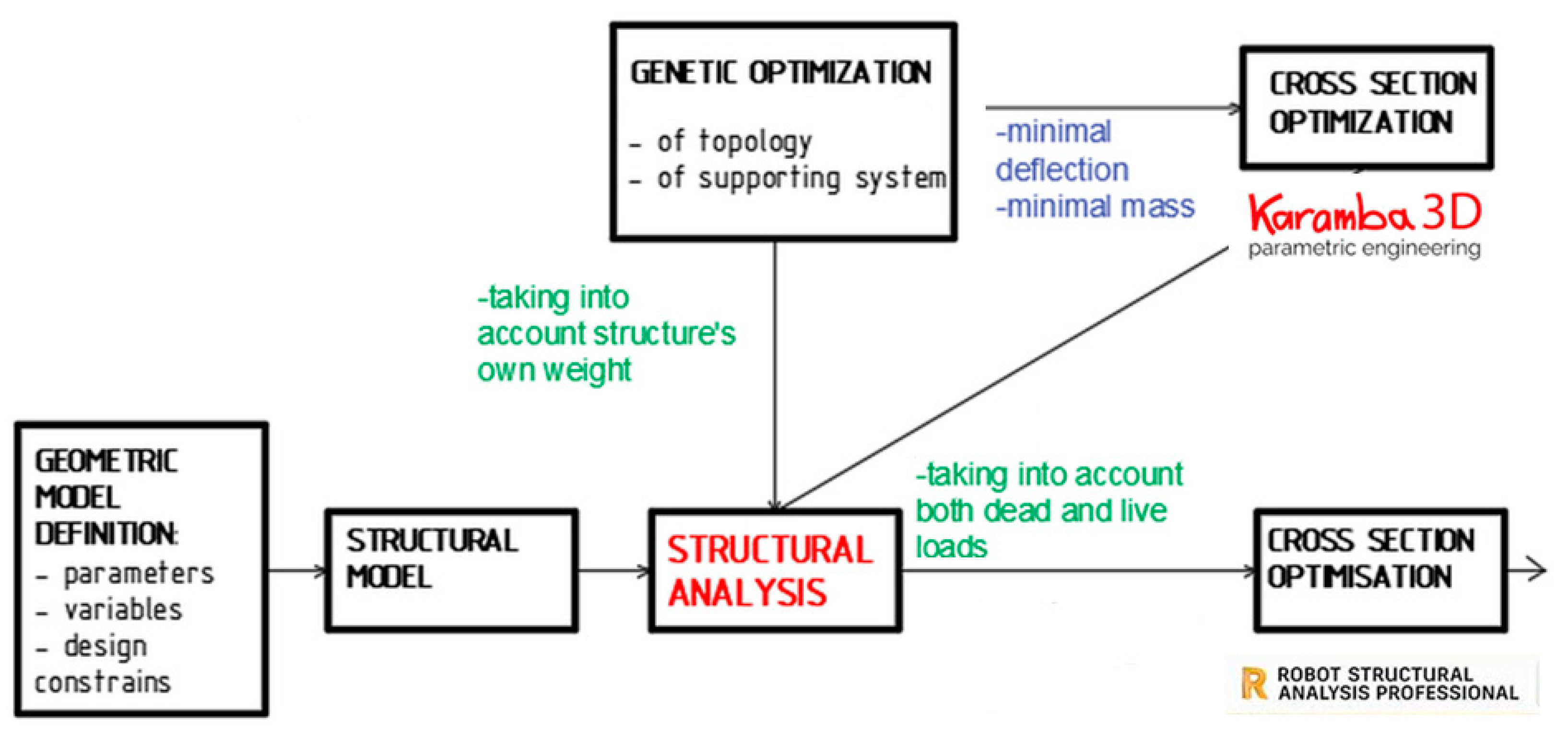
The validation of the functionality of the shaping tools mentioned above, as well as benefits of their application to improve and integrate both architectural and structural shaping, are accomplished by implementing them for the analysis of the curvilinear steel bar structures. The overall strategy of integrated process that will be used for shaping curvilinear steel bar structures is presented by the scheme, Figure 1.
In general, shaping begins with the creation of a parametric, geometric model of a structure using Grasshopper. On the basis of the geometric model and assumed boundary conditions regarding supports and loads, as well as joints and material properties (intended for the shaped structure), the structural model is created. It is later subjected to a two-stage analysis. The first analysis is linked with evolutionary structural optimization (ESO), in which topology and cross-sections of structures’ bars are optimized taking into account structure’s self-weight as the optimization criterion. The optimal grid pattern is selected based on the minimum mass and deflection, as well as the positions of established optimal supports. Next, the structural model for the selected grid pattern is completed with any possible live loads and further the structural analysis is performed by Autodesk Robot Structural Analysis software.
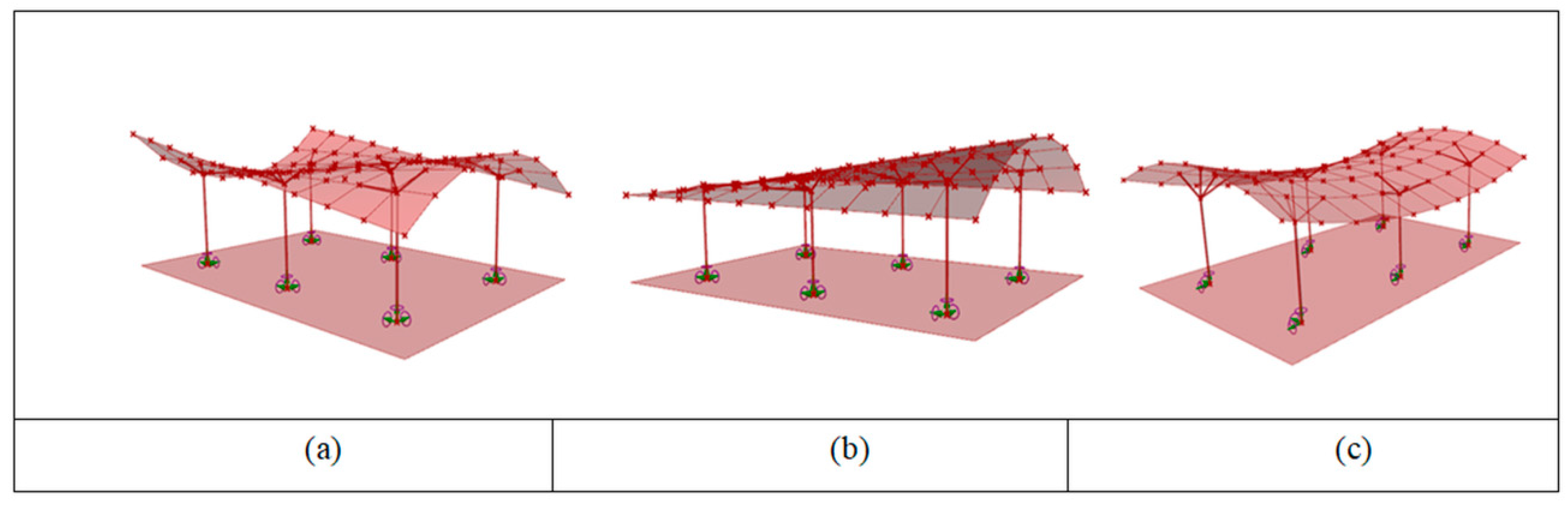
Shaping strategy presented in the paper consists in shaping of curvilinear steel bar structures by placing the structural nodes on the so-called base surface. This surface is selected from the groups of surfaces with advantageous features both in terms of shape and the possibility of their subdivision. As the basic surfaces for shaping structures are proposed skew ruled surfaces, especially Catalan surfaces described in [29]. Parametric modelling of concrete roofs composed of repetitive units of Catalan surfaces is shown in [30], whereas parametric approach to shaping of curvilinear steel bar structures based on Enneper surface is presented in [31]. However, the subject of this research are three various roof structures, being the curvilinear steel bar structures of cylindroid shape, conoid shape, and hyperbolic paraboloid shape. Each structure is composed of roof’s lattice created on the basis of a single-shell. The lattice is supported by six vertical columns, however, each column is joined with the lattice’s nodes by four branches.
3. Results
3.1. Geometric Shaping of the Base Surfaces
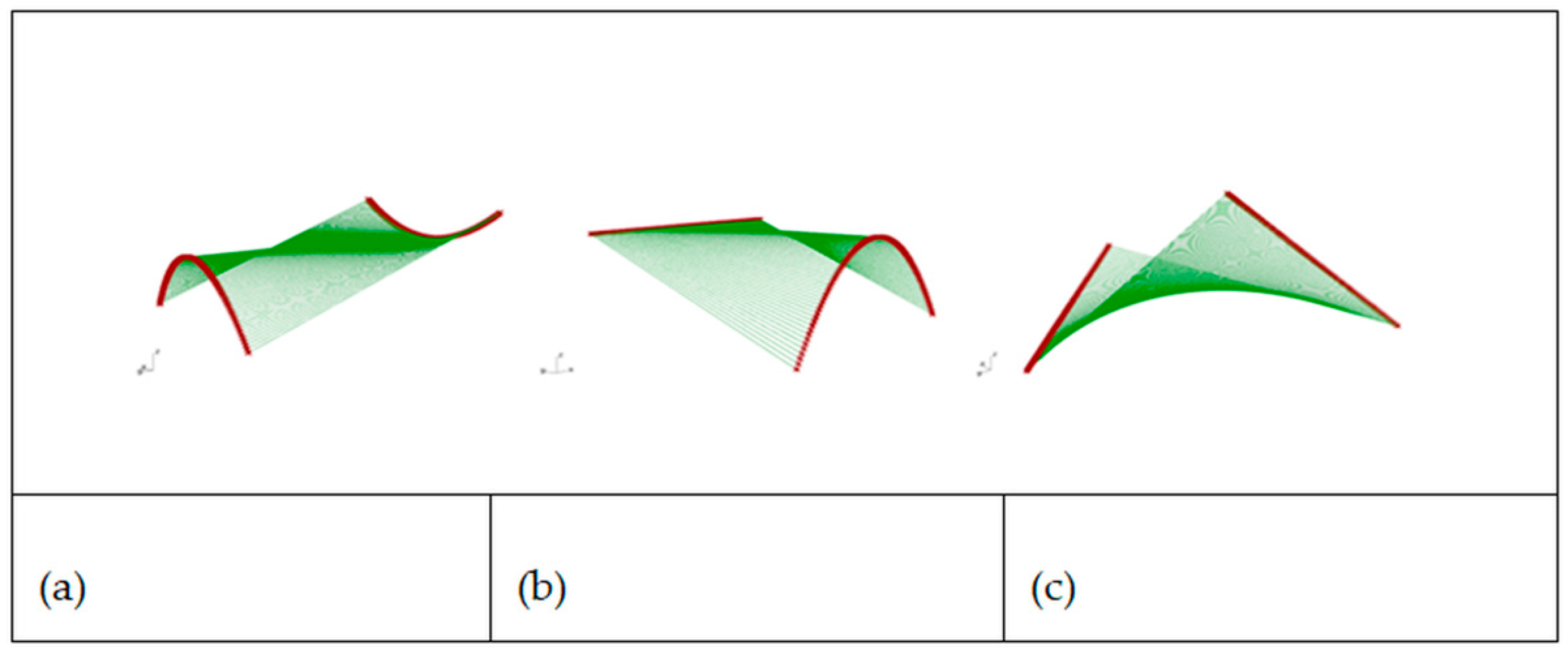
The first step to conduct the analysis is the creation of geometric model of the Catalan surface, which will next constitute the base surface for placing structural nodes of the roofs’ lattices. Each Catalan surface is determined by two directrix lines and the director plane to which all surface rulings are parallel. In the case when both directrix lines are curved lines, a cylindroid can be obtained; when one directrix is a straight line, a conoid can be obtained. However, when both directrices are mutually oblique straight lines the Catalan surface is a hyperbolic paraboloid, Figure 2.
In order to prepare Grasshopper’s scrips of the roof structures, two spatial lines were distinguished, which were then divided into the same number of elements. The series of points of both lines were next joined by lines to define a base surface. The surface was discretized and the nodes of the quadrate grid were placed on it. Additionally, parametric models of six supporting columns and joining branches were prepared, which finally gave a parametric model of a whole structure. It is worth mentioning that hyperbolic paraboloid can be established by two skew lines and alternatively as a translational surface. Due to the fact that the latter is a regular surface more suited for a single roof, it has been chosen for further analysis, Figure 3.
The columns are located symmetrically on the rectangular plan. The plan area equals 150 m2, whereas the length of the rectangle equals 15 m and the width of the rectangle equals 10 m, Figure 3.
It has been assumed that the columns are placed within the rectangular plan, however, they cannot be placed farther than two meters from the place’s border. Their position is described by coordinates x, y, with the unit adopted on each axis equal to 1 m. The best columns positions is to be established by means of the optimization process.
Appropriate positioning of structure’s supports is always one of the most important and practical issues in engineering and plays a key role in improving of structure’s efficiency. Due to this fact, optimization of support location of the structure is the topic of great importance. Several methods have been developed for determination of the best location of the supports. They can be broadly divided into gradient-based methods and non-gradient methods [32]. The presented case study has applied evolutionary optimization method (EO) for finding the best location of columns.
3.2. Results of Evolutionary Optimization Performed by Galapagos
Optimization is to find proper location of supports, position of the branches’ node, proper grid pattern and estimate elements’ cross sections.
The first step is to optimize the structure loaded with its own weight, taking the minimal mass as the optimization criterion.
The data needed for the optimization are listed in the below points:
- -
- Due to Ultimate Limit States (ULS) the it should be respectively:
- -
- Ed/Rd ≤ 1 at each cross section, where: Ed–is a design
- -
- value of the effects of actions, Rd represents the design value of the corresponding resistance, however this verification is fulfilled automatically
- -
- Due to Serviceability Limit States (SLS) deflection limit for any load case should fulfill the condition f = L/250, where L it is a span of the structure, so for the considered structures f ≤ 40 mm
- -
- Kind of the structural material applied: steel S235.
Established variables:
- -
- Dimensions of the rectangular plan: 15 m × 10 m
- -
- Number of supports: 6
- -
- Height of the whole structure: 5 m
- -
- Height of the roof’s surface: 2 m
- -
- Self-weight as the sum of the lattice’s weight and columns’ weight as well as cladding weight calculated by Karamba 3D for each structure individually
- -
- Kind of cladding: steel with weight of 0.07 kN/m2 (thickness of the steel sheet equal to 5 mm)
- -
- Elements’ cross sections: circular hollow, walls’ thickness not less than 3.2 mm
Variables for optimization:
- -
- Location of the supports: within the rectangular plan, however no farer than 2 meters from the place’s border
- -
- Minimal bars’ length: 1.0 m–1.5 m
- -
- Maximum bars’ length: 1.5 m–2.0 m
- -
- Location of the column branching node in the scope of 70% d–90% d, where d is the distance of the column’s base to the roof’s surface
- -
- Cross section diameter: 4.83 cm–6.0 cm for lattice and column branches
- -
- 4.83 cm–7.0 cm for columns
Each of the canopy roofs is considered as a curvilinear steel bar structure with quad grid pattern. The optimal column positions, as well as optimal members’ dimensions for each structure under self-load are presented in Table 1.
Analyzing the results presented in the above table, it can be stated that the structure with the roof of hyperbolic paraboloid shape is the lightest and thus the most economical. However, in order to properly evaluate the structures, further analysis should be carried out using different load combinations.
3.3. Results of the Structural Optimization Performed by Autodesk Robot Structural Analysis Software
Geometric models of canopy roof structures with established optimal column positions have been exported to Autodesk Robot Structural Analysis Professional software for further calculations. Border conditions regarding snow and wind zones were established for the city of Rzeszow, Poland. However, snow load has been established for each of the structures individually dependently on the roof’s shape. Due to the assumed location, the influence of seismic forces has been omitted.
The details of the taken assumptions, as well as the structural analysis performed are given below.
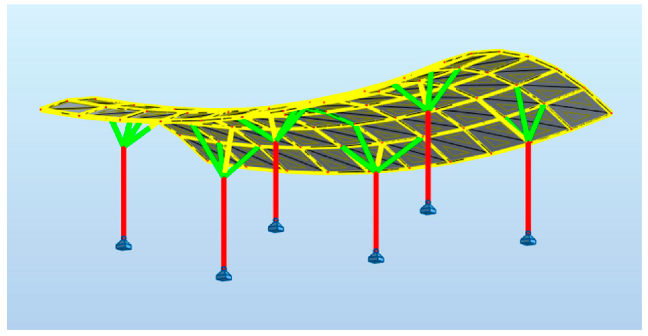
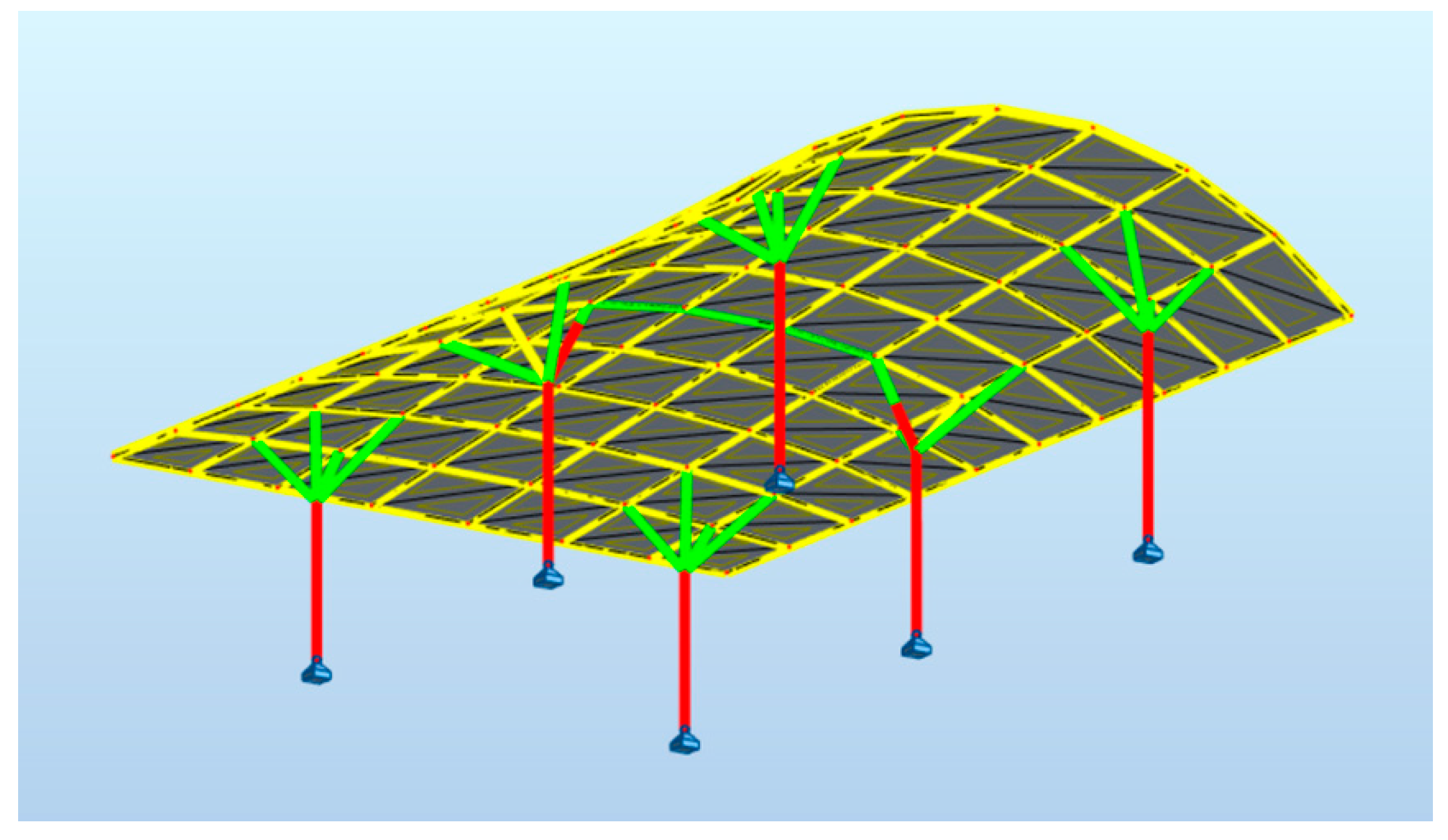
3.3.1. Hyperbolic Paraboloid Canopy Roof
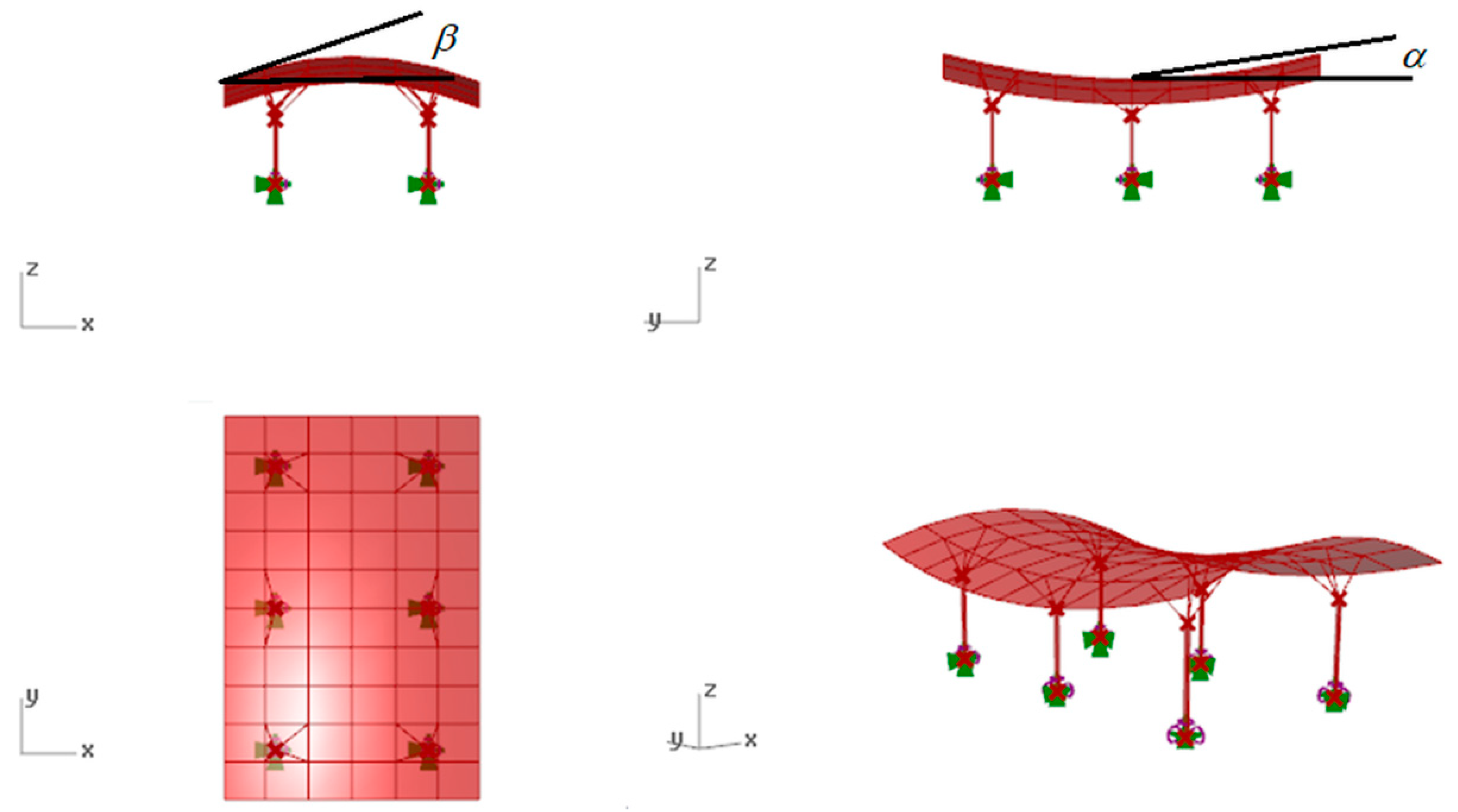
Due to roof’s shape and according to [36], shape coefficient μi for snow load calculation is taken similarly as for the cylindrical roofs. Due to this fact μi for β ≤ 60° is established in the following way, Figure 4:
- μ1 = 0.8 in the case of even load, (the case of evenly spreading snow on the roof)
Due to the fact, that considered roof’s surface is a saddle surface some snow can accumulate in the central part of the roof Figure 4. Therefore, additionally snow drifts are considered.
In this case shape coefficient μ2 is established like for butterfly roof with the angle of slope of α = 10°, therefore, μ2 = 0.2 + 0.8 × 10/30, Figure 4.
Due to the maps on bars of the presented distribution of axial force Fx shown in Figure 5, the bars of the structure has been divided into free groups: lattice’s bars, branches, and columns. The structure has been optimized assuming mass as an optimization criterion.
The total mass of the structure due to structural optimization equals 2482.405 kg, whereas characteristics of the structure’s members is presented in Table 2.
3.3.2. Cylindroid Canopy Roof
In the case of cylindroid canopy roof like in the case of the hyperbolic paraboloid canopy roof three possibilities of snow loads are calculated:
- Even snow load, (the case of evenly spreading snow on the roof);
- Uneven snow load, (the case of uneven distribution of snow on the roof resulting from the shape of the roof and the guidelines contained in [36]);
- Drifted snow load, (taking into account exceptional situations, when snow can be particularly cumulated in the recessed part of the roof according to [36].
Due to roof’s shape the coefficient μi is established respectively [36]:
- μ1 = 0.8 in the case of even load,
- μ3 = 2 in the case of uneven snow load
- μ2 = 1.33 in the case of drifted snow load
μ2 is calculated for a half of the roof as for butterfly roof with α = 20°, Figure 6.
Due to the maps on bars of the distribution of axial force Fx presented in Figure 7, the members of the structure has been divided into free groups: lattice’s bars, branches, and columns.
The characteristics of the structure due to structural optimization are presented in the Table 3. The total mass of the presented structure equals 2670.236 kg.
3.3.3. Conoid Canopy Roof
Due to the shape of the conoid canopy roof only two cases of snow load are analyzed, as shown in Figure 8:
- Even snow load, (the case of evenly spreading snow on the roof)
- Uneven snow load, (the case of uneven distribution of snow on the roof resulting from the shape of the roof and the guidelines contained in [36]).
Shape coefficient μi is established as follows [36]:
- μ1 = 0.8 in the case of even load,
- μ3 = 2 in the case of uneven snow load.
However, due to the maps on bars of axial force Fx presented in Figure 9, as in the previous cases, the bars of the structure has been divided into free groups: lattice’s bars, branches, and columns.
The characteristics of the structure due to structural optimization is presented in the Table 4. The total mass of the structure equals 2643.048 kg.
The results of the optimization given in Table 2, Table 3 and Table 4 show that the canopy roof with hyperbolic parabolic shape has the smallest mass. Due to this fact, the structure with the roof of the hyperbolic paraboloid shape is the most economical.
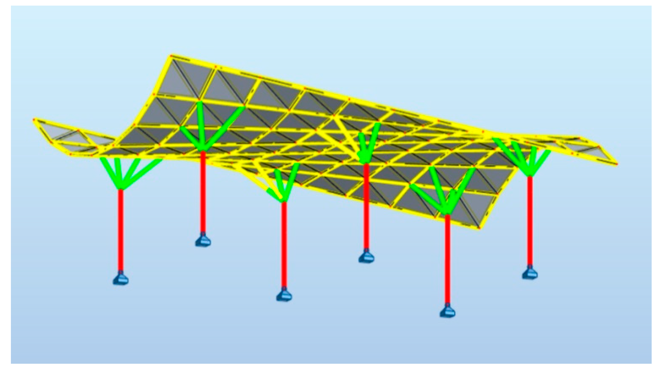
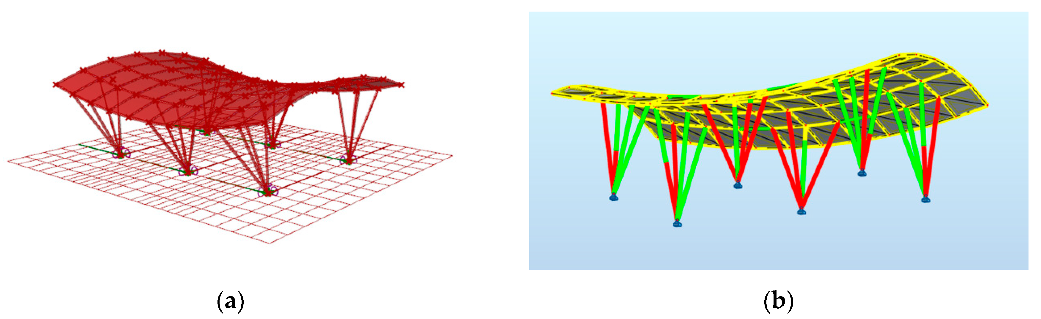
As the alternative structure for the hyperbolic paraboloid, a canopy roof with six single columns can be a similar roof, but supported by six groups of branches, as presented in Figure 10.
Each group is composed of four branches which are joined at the foundation node, whereas branches of each group join the foundation node with four closest grid nodes. The location of the supports, as well as the pattern of the roof structure is assumed to be the same as in the case of the hyperbolic paraboloid canopy roof with six single columns presented in Figure 5. The maps on bars presented distribution of axial force Fx in the considered structure are shown in Figure 10.
The results of the structural analysis and optimization performed by Autodesk Robot Structural Analysis software give the optimal members’ sizes, Table 5. Total mass of the structure equals 2354.531 kg.
Analyzing the mass of hyperbolic paraboloid canopy roofs supported by six single columns and by six groups of branches, it can be stated that the structure supported by six groups of branches is lighter. Moreover, this structure is compound only of two groups of members. Due to this fact, it is the most efficient.
4. Discussion
Optimal design of structures is an important direction for the development of research on structures of various types. Optimization can deal with shape, topology [37] as well as the strength properties of structures. Sometimes it is a result of experimental research on novel methods, or the selection of the best technique [38]. The presented research is a contribution to the research conducted in the field of design optimization using modern digital tools. It showed the possibility of simultaneous optimization of the geometry and topology of the structure in order to obtain the best possible strength properties.
The research revealed differences in the weight of the various roof structures depending on the kind of the surface applied. The presented method of shaping curvilinear steel bar structures consisting in placing structural nodes on a given base surface is convenient due to the possibilities of using the potential of Rhinoceros 3D and Grasshopper to create such structures. The Catalan surfaces being ruled surfaces and constituting a set of straight lines, create the possibility of the surfaces’ regular divisions in order to apply grids of bars, especially quad grids. However, the most effective surface for shaping steel bar structures, from among considered surfaces, turned out to be a hyperbolic paraboloid, which has properties similar to the properties of minimal surfaces. The roof of hyperbolic paraboloid shape turn out to be the lightest and the most efficient. However, the research also proved that this structure supported by multi-branch columns is lighter than the identical structure supported by single columns.
The use of quadrilateral grids always makes the structure lighter. However, the hyperbolic paraboloid is the only surface of the Catalan surfaces on which a grid of flat quadrilaterals can be used. This is due to the fact that in the case of a hyperbolic paraboloid, which is a translational surface and always has a rectangular grid placed on it, the two sides of each panel are parallel. This guarantees that panels’ surfaces are flat, which is important due to the production cost. The other surfaces that is cylindroid and conoid do not have such a property, so they cannot be filled with flat panels.
5. Conclusions
Modern tools for shaping structures working in the environment of Rhinoceros 3D such as Grasshopper and Karamba 3D enable algorithmic-aided shaping structures, while allowing the free flow of information between the geometric model and structural model, which enables shaping of efficient structures. The examples of curvilinear steel bar structures obtained as a result of optimization presented in the paper may constitute some proposals of roof structures solutions. However, the structures should be subjected to further optimization due to the adopted solutions for joining bars, which are important in the case of steel bar structures. Also, studies related to unification of the lengths of bars used in the considered structures will be the subject of further consideration.
Funding
This research was funded by Rzeszow University of Technology.
Conflicts of Interest
The authors declare no conflict of interest.
References
- Oxman, R. Theory and design in the first digital age. Des. Stud. 2006, 27, 229–265. [Google Scholar] [CrossRef]
- Hewitt, M. Representational Forms and Modes of Conception; an Approach to the History of Architectural Drawing. J. Arch. Educ. 2014, 39, 2–9. [Google Scholar]
- Unwin, S. Analyzing architecture through drawing. Build. Res. Inf. 2007, 35, 101–110. [Google Scholar] [CrossRef]
- Dzwierzynska, J. Direct construction of Inverse Panorama from a Moving View Point. Procedia Eng. 2016, 161, 1608–1614. [Google Scholar] [CrossRef]
- Dzwierzynska, J. Computer-Aided Panoramic Images Enriched by Shadow Construction on a Prism and Pyramid Polyhedral Surface. Symmetry 2017, 9, 214. [Google Scholar] [CrossRef]
- Dzwierzynska, J. Single-image-based Modelling Architecture from a Historical Photograph. IOP Conf. Ser. Mater. Sci. Eng. 2017, 245, 062015. [Google Scholar] [CrossRef]
- Dzwierzynska, J. Reconstructing Architectural Environment from a Panoramic Image. IOP Conf. Ser. Earth Environ. Sci. 2016, 44, 042028. [Google Scholar] [CrossRef] [Green Version]
- Biagini, C.; Donato, V. Behind the complexity of a folded paper. In Proceedings of the Conference on Modelling from Digital to Physical, Milano, Italy, 11–12 November 2013; pp. 160–169. [Google Scholar]
- Luo, Y.; Dias, J.M. Development of a Cooperative Integration System for AEC Design. In Cooperative Design, Visualization, and Engineering (CDVE 2004); Luo, Y., Ed.; Lecture Notes in Computer Science; Springer: Berlin/Heidelberg, Germany, 2004; Volume 3190. [Google Scholar] [CrossRef]
- Wang, J.; Chong, H.-Y.; Shou, W.; Wang, X.; Guo, J. BIM-Enabled design Collaboration for Complex in Cooperative Design, Visualization, and Engineering Building. In Proceedings of the 9-th International Conference (CDVE 2013), Alcudia, Mallorca, Spain, 22–25 September 2013; Luo, Y., Ed.; Springer: Heindelberg, Germany; New York, NY, USA; Dordrecht, The Netherlands; London, UK, 2013; ISBN 978-3-642-40840-3. [Google Scholar]
- Kolarevic, B. Architecture in the Digital Age: Design and Manufacturing, 1st ed.; Spon Press: London, UK, 2003; pp. 20–98. ISBN 0-415-27820-1. [Google Scholar]
- Barlish, K.; Sullivan, K. How to measure the benefits of BIM—A case study approach. Autom. Constr. 2012, 24, 149–159. [Google Scholar] [CrossRef]
- Elango, M.; Devadas, M.D. Multi-Criteria Analysis of the Design Decisions in architectural Design Process during the Pre-Design Stage. Int. J. Eng. Technol. 2014, 6, 1033–1046. [Google Scholar]
- Turrin, M.; von Buelow, P.; Stouffs, R. Design explorations of performance driven geometry in architectural design using parametric modeling and genetic algorithms. Adv. Eng. Inform. 2011, 25, 656–675. [Google Scholar] [CrossRef]
- Wortmann, T.; Tuncer, B. Differentiating parametric design: Digital Workflows in Contemporary Architecture and Construction. Des. Stud. 2017, 52, 173–197. [Google Scholar] [CrossRef]
- Hardling, J.E. Meta-parametric Design. Des. Stud. 2017, 52, 73–95. [Google Scholar] [CrossRef]
- Oxman, R. Thinking difference: Theories and models of parametric design thinking. Des. Stud. 2017, 52, 4–39. [Google Scholar] [CrossRef]
- Bhooshan, S. Parametric design thinking: A case study of practice-embedded architectural research. Des. Stud. 2017, 52, 115–143. [Google Scholar] [CrossRef]
- Kuś, S. General principles of shaping the structure. In General Building Construction, Building Elements and Design Basics; Arkady: Warsaw, Poland, 2011; Volume 3, pp. 12–71. (In Polish) [Google Scholar]
- Foraboschi, P. The central role played by structural design in enabling the construction of buildings that advanced and revolutionized architecture. Constr. Build. Mater. 2016, 114, 956–997. [Google Scholar] [CrossRef]
- Woliński, S. On the criteria of shaping structures. Sci. Pap. Rzesz. Univ. Technol. 2011, 276, 399–408. [Google Scholar]
- Januszkiewicz, K.; Banachowicz, M. Nonlinear Shaping Architecture Designed with Using Evolutionary Structural Optimization Tools. IOP Conf. Ser. Mater. Sci. Eng. 2017, 245. [Google Scholar] [CrossRef]
- Dzwierzynska, J. Rationalized Algorithmic-Aided Shaping a Responsive Curvilinear Steel Bar Structure. Buildings 2019, 9, 61. [Google Scholar] [CrossRef]
- Foraboschi, P. Optimal design of glass plates loaded transversally. Mater. Des. 2014, 62, 443–458. [Google Scholar] [CrossRef]
- Minseok, K. A Study on Efficient Approaches for Grasshopper Programming in Architectural Design Process. Korean J. Comput. Des. Eng. 2016, 21, 453–461. [Google Scholar]
- Available online: https://www.rhino3d.com/ (accessed on 19 March 2019).
- Preisinger, C. Linking Structure and Parametric Geometry. Arch. Des. 2013, 83, 110–113. [Google Scholar] [CrossRef]
- Autodesk. Available online: https://www.autodesk.com/ (accessed on 25 February 2019).
- Pottman, H.; Asperl, A.; Hofer, M.; Kilian, A. Architectural Geometry, 1st ed.; Bentley Institute Press: Exton, PA, USA, 2007; pp. 35–194. ISBN 978-1-934493-04-5. [Google Scholar]
- Dzwierzynska, J.; Prokopska, A. Pre-Rationalized Parametric Designing of Roof Shells Formed by Repetitive Modules of Catalan Surfaces. Symmetry 2018, 10, 105. [Google Scholar] [CrossRef]
- Dzwierzynska, J. Shaping curved steel rod structures. Tech. Trans. Civ. Eng. 2018, 8, 87–98. [Google Scholar] [CrossRef]
- Wang, D. Optimization of support positions to minimize the maximal deflection of structure. Int. J. Solids Struct. 2004, 41, 7445–7458. [Google Scholar] [CrossRef]
- PN-EN 1990: 2004. Eurocode. Basis of Structural Design; PKN: Warsaw, Poland, 2004. (In Polish) [Google Scholar]
- PN-EN 1993-1-1:2006. Eurocode 3. Design of Steel Structures. Part 1-1: General Rules and Rules for Buildings; PKN: Warsaw, Poland, 2006. (In Polish) [Google Scholar]
- PN-EN 1991-1-1:2004. Eurocode 1. Actions on Structures. Part 1-1: General Actions-Densities, Self-Weight, Imposed Loads for Buildings; PKN: Warsaw, Poland, 2004. (In Polish) [Google Scholar]
- PN-EN 1991-1-1:2004. Eurocode 1. Actions on Structures. Part 1-3: General Actions-Snow Loads; PKN: Warsaw, Poland, 2004. (In Polish) [Google Scholar]
- Tajs-Zielińska, K.; Bochenek, B. Topology Optimization-Engineering Contribution to Architectural Design. IOP Conf. Ser. Mater. Sci. Eng. 2017, 245. [Google Scholar] [CrossRef]
- Foraboschi, P. Effectiveness of novel methods to increase the FRP-masonry bond capacity. Compos. Part B Eng. 2016, 107, 214–232. [Google Scholar] [CrossRef]
Figure 1.
Basic scheme of the integrated shaping process.

Figure 2.
Typical examples of Catalan surfaces; respectively from the left: (a) a cylindroid; (b) a conoid; (c) a hyperbolic paraboloid.
Figure 2.
Typical examples of Catalan surfaces; respectively from the left: (a) a cylindroid; (b) a conoid; (c) a hyperbolic paraboloid.

Figure 3.
Considered canopy roof bar structures of: (a) cylindroid shape; (b) conoid shape; (c) hyperbolic paraboloid shape.
Figure 3.
Considered canopy roof bar structures of: (a) cylindroid shape; (b) conoid shape; (c) hyperbolic paraboloid shape.

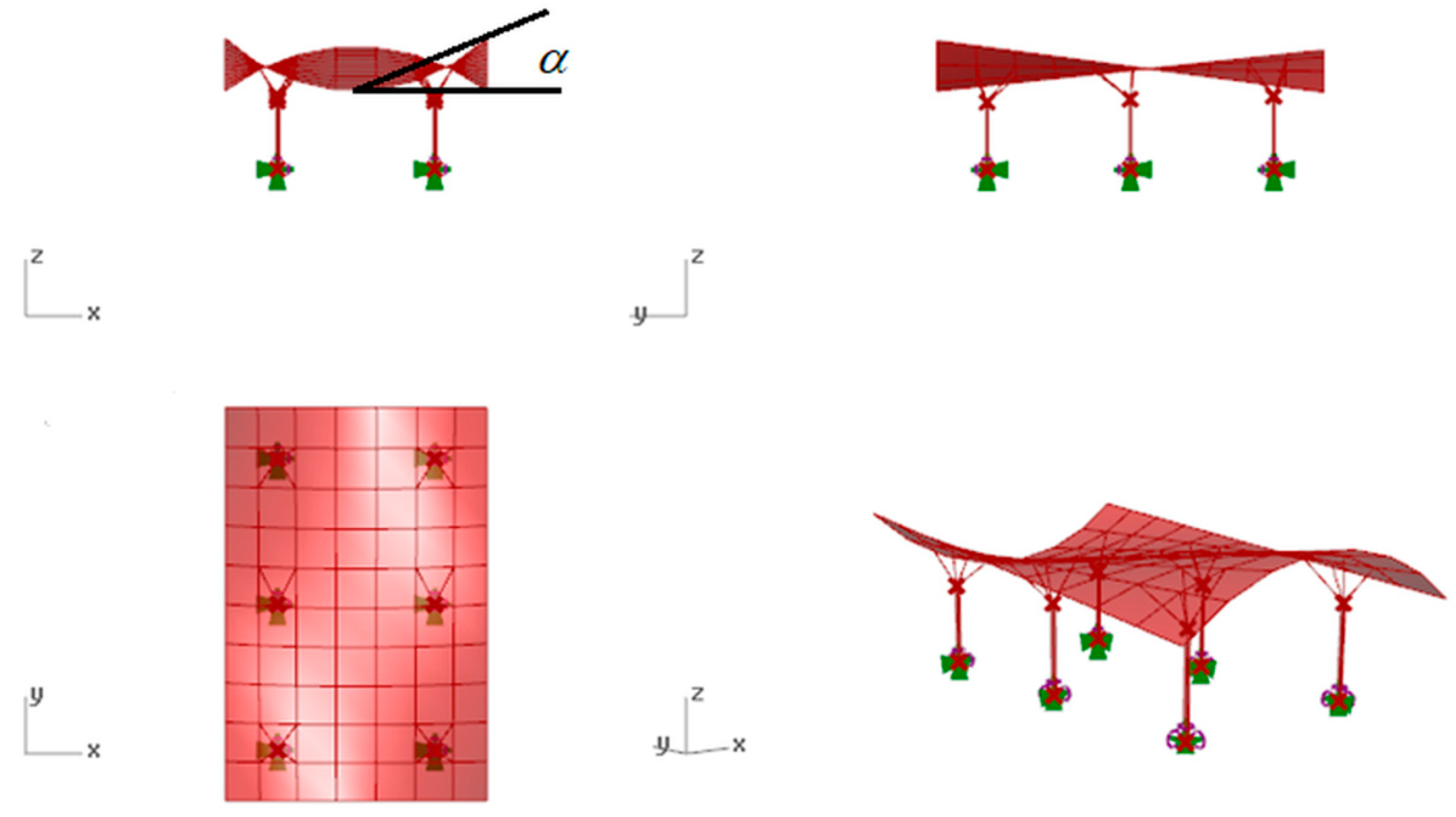
Figure 4.
Views of hyperbolic paraboloid canopy roof—determination of the roof inclination angle.

Figure 5.
Maps on bars—distribution of axial force FX.

Figure 6.
Views of the cylindroid canopy roof - determination of the roof inclination angle.

Figure 7.
Maps on bars—distribution of axial force FX.

Figure 8.
Views of the conoid canopy roof—determination of the roof inclination angle.

Figure 9.
Maps on bars—distribution of axial force FX.

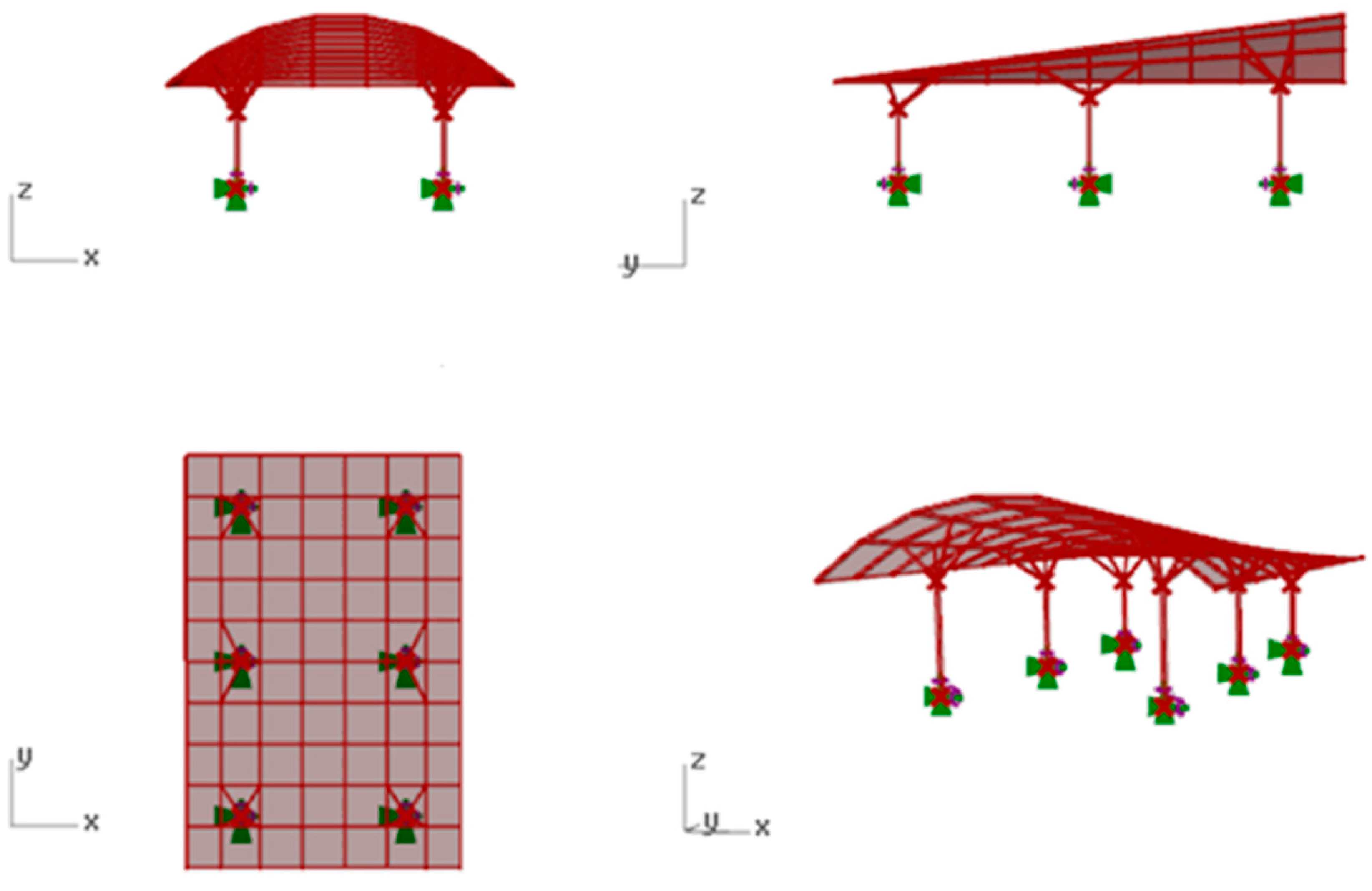
Figure 10.
The roof supported by six groups of branches (a) Perspective view (b) Maps on bars – distribution of axial force FX.
Figure 10.
The roof supported by six groups of branches (a) Perspective view (b) Maps on bars – distribution of axial force FX.


Table 1.
Results of the single objective structural optimization achieved by means of Grasshopper for three structures.
Table 1.
Results of the single objective structural optimization achieved by means of Grasshopper for three structures.
| Bars’ (Lattice and Branches) Cross Sections Radius/Wall Thickness [mm] | Column Cross Section Radius/Wall Thickness [mm] | Column’s Length [m] | Maximum Displacement [mm] | Ratio [%] | Column Position in Coordinates x, y | Mass [kg] |
|---|---|---|---|---|---|---|
| Structure 1–hyperbolic paraboloid canopy roof with grid divisson: 6 × 10 | ||||||
| 4.83/0.32 | 7.00/0.32 | L = 70%d | 21 | 30 | x1 = 2.0, y1 = 1.85 x2 = 8.0, y2 = 1.85 x3 = 2.0, y3 = 7.5 x4 = 8.0, y4 = 7.5 x5 = 2.0, y5 = 13.15 x6 = 8.0, y6 = 13.15 | 1016.95 |
| Structure 2–cylindroid canopy roof with grid division: 7 × 10 | ||||||
| 4.83/0.32 | 7.00/0.32 | l= 70%d | 28 | 34 | x1 = 2.0, y1 = 2.0 x2 = 8.0, y2 = 2.0 x3 = 2.0, y3 = 7.5 x4 = 8.0, y4 = 7.5 x5 = 2.0, y5 = 13.0 x6 = 10.0, y6 = 13.0 | 1058.73 |
| Structure 3–conoid canopy roof with grid division: 7 × 10 | ||||||
| 4.83/0.32 | 7.00/0.32 | L = 70%d | 28 | 35 | x1 = 2.0, y1 = 1.94 x2 = 8.0, y2 = 1.94 x3 = 2.0, y3 = 7.5 x4 = 8.0, y4 = 7.5 x5 = 2.0, y5 = 13.06 x6 = 8.0, y6 = 13.06 | 1047.61 |
Table 2.
Dimensioning of the considered hyperbolic paraboloid roof structure due to structural optimization.
Table 2.
Dimensioning of the considered hyperbolic paraboloid roof structure due to structural optimization.
| Kind of Member | Cross Section Radius/Wall Thickness [mm] | Ratio [%] |
|---|---|---|
| Lattice’s bars | 101.6/3.6 | 92 |
| Branches | 106.6/3.2 | 94 |
| Columns | 139.0/4.5 | 94 |
Table 3.
Dimensioning of the considered conoid roof structures due to structural optimization.
| Kind of Member | Cross Section Radius/Wall Thickness [mm] | Ratio [%] |
|---|---|---|
| Lattice’s bars | 114.3/3.2 | 93 |
| Branches | 101.6/3.6 | 85 |
| Columns | 159.0/4.5 | 95 |
Table 4.
Dimensioning of the considered roof structures due to structural optimization.
| Kind of Member | Cross Section Radius/Wall Thickness [mm] | Ratio [%] |
|---|---|---|
| Lattice’s bars | 101.6/3.6 | 90 |
| Branches | 114.4/4.0 | 79 |
| Columns | 139.7/4.0 | 46 |
Table 5.
Dimensioning of the considered roof structure due to structural optimization.
| Kind of Member | Cross Section Radius/Wall Thickness [mm] | Ratio [%] |
|---|---|---|
| Lattice’s bars | 101/3.2 | 88 |
| Branches | 76.1/3.6 | 85 |
© 2019 by the author. Licensee MDPI, Basel, Switzerland. This article is an open access article distributed under the terms and conditions of the Creative Commons Attribution (CC BY) license (http://creativecommons.org/licenses/by/4.0/).
Share and Cite
MDPI and ACS Style
Dzwierzynska, J. Integrated Parametric Shaping of Curvilinear Steel Bar Structures of Canopy Roofs. Buildings 2019, 9, 72. https://doi.org/10.3390/buildings9030072
AMA Style
Dzwierzynska J. Integrated Parametric Shaping of Curvilinear Steel Bar Structures of Canopy Roofs. Buildings. 2019; 9(3):72. https://doi.org/10.3390/buildings9030072
Chicago/Turabian StyleDzwierzynska, Jolanta. 2019. "Integrated Parametric Shaping of Curvilinear Steel Bar Structures of Canopy Roofs" Buildings 9, no. 3: 72. https://doi.org/10.3390/buildings9030072
Note that from the first issue of 2016, this journal uses article numbers instead of page numbers. See further details here.