Graph-Based Construction of 3D Korean Giwa House Models


Department of Game & Mobile, Faculty of Computer Engineering, Keimyung University, Daejeon 40601, Korea
Buildings 2019, 9(3), 68; https://doi.org/10.3390/buildings9030068
Submission received: 19 February 2019
/
Revised: 12 March 2019
/
Accepted: 14 March 2019
/
Published: 18 March 2019
(This article belongs to the Special Issue IT in Design, Construction, and Management)
Abstract
:This paper proposes a graph-based algorithm for constructing 3D Korean traditional houses automatically using a computer graphics technique. In particular, we target designing the most popular traditional house type, a giwa house, whose roof is covered with a set of Korean traditional roof tiles called giwa. In our approach, we divided the whole design processes into two different parts. At a high level, we propose a special data structure called ‘modeling graphs’. A modeling graph consists of a set of nodes and edges. A node represents a particular component of the house and an edge represents the connection between two components with all associated parameters, including an offset vector between components. Users can easily add/ delete nodes and make them connect by an edge through a few mouse clicks. Once a modeling graph is built, then it is interpreted and rendered on a component-by-component basis by traversing nodes in a procedural way. At a low level, we came up with all the required parameters for constructing the components. Among all the components, the most beautiful but complicated part is the gently curved roof structures. In order to represent the sophisticated roof style, we introduce a spline curve-based modeling technique that is able to create curvy silhouettes of three different roof styles. In this process, rather than just applying a simple texture image onto the roof, which is widely used in commercial software, we actually laid out 3D giwa tiles on the roof seamlessly, which generated more realistic looks. Through many experiments, we verified that the proposed algorithm can model and render the giwa house at a real time rate.
1. Introduction
East Asian architecture has a long history and aesthetic value along with its own cultural tradition. One of the differences between western and east-Asian traditional architecture is the roof design [1]. In particular, Korean traditional roof design has its own unique style that is different from other East Asian countries such as China and Japan, even though these countries have been influenced by each other for a long time. From the Korean roof design structure’s inner layout to the building materials outside [1,2,3], it shows environmentally-friendly aspects as well as unique characteristics. The most common and widely used house design for higher social classes was the ‘giwa’ house. Giwa is a soil-baked roof tile. The giwa house has its own unique structure, style and aesthetic, as well as unique functional aspects [2,4].
The 3D reconstruction of Korean traditional architecture such as giwa houses through computer graphics technology has the following important aspects: First, a lot of digital contents including games and interactive applications require 3D models of architecture. Therefore, if we can obtain a precise 3D geometrical model of cultural contents without requiring any laborious and tedious work from a graphics designer, these models will be used in scientific research as well as for commercial purposes such as virtual museums [5,6]. Second, although current technologies such as 3D scanning are able to convert precious antique items into digital ones, these technologies are not useful for huge objects like buildings. Moreover, even when these technologies can be used, the huge amount of digital data they entail always provides problems.
Although manual modeling might generate realistic 3D models through commercial 3D software such as Maya and 3DMAX [7], it is hard to modify them afterwards. For example, even adding new components or changing some components of existing objects needs a lot of time to achieve.
In this paper, we address problems of 3D modeling for Korean giwa houses and propose a procedural way of modeling. That is, all modeling can be carried out by an algorithm using a simple visual programming interface without any manual specifying of geometrical primitives such as points and lines. One of the difficult parts of constructing the architecture through the procedural method is how we can model curvy components. This is important for giwa houses because the silhouette of curvy roof is aesthetically important [8]. We propose a procedural method for constructing three different roof styles that have a curvy shape through a parameterized spline-curve method [9,10]. We believe that our proposed method has the following novelties and contributions.
- Parameterization of procedural modeling of Korean giwa houses: To the best of our knowledge, not much research has been done on constructing Korean traditional houses, especially giwa houses. This paper comes up with required parameters for modeling three different giwa houses procedurally whose roofs are quite complicated and curvy using a parameterized spline technique [10]. This method can be extended easily for the modeling of other East Asian architecture such as that of Japan and China because they share similarities in shapes [1].
- Graph based modeling approach: One of the disadvantages of existing procedural techniques such as shape-grammars is that they are suitable for western architectures where most architecture building has a boxy shape and does not have many curvy roofs [9,11]. In addition, they have to write a script manually. We propose a graph-based modeling interface that encapsulates the geometrical data and all required parameters into a graph structure.
Compared with the widely used scene-graph based modeling technique [12], our graph-based interface operates on a higher level and is not similar to a tree structure. Our modeling graph consists of several nodes and edges as usual. Like a scene-graph, the nodes represent components of the house and the edges represent the geometrical connection between components. However, one difference of the scene-graph is that we associated an edge, which are all directed, with a set of parameters for the entering node, which is the destination node of the edge. The parameters include the 3D offset distance between two components connected by the edge, sizes, colors and all values for specifying the styles of components. Also, our modeling graph allows a self-looped edge that represents a repetition of specific components and two nodes can be connected with multiple edges. Figure 1 shows the comparison between the conventional scene-graph and our modeling graph.
Once the modeling graph is constructed, the actual modeling of architectural project is carried out by traversing the graph from the starting node and moving along the edges until it reaches the ending node. When the graph arrives at a specific node while traversing, the algorithm starts to construct the component by calling required functions with all parameters provided from the incoming edge.
To validate our algorithm, we made a computer graphics software tools on the Microsoft Windows 10 platform. Our system operates in two steps. At the first step, we generate modeling graphs by using a simple modeling graph tool. The tool has a set of in-built nodes. Users only need to load a set of parameters for edges and make connections between nodes through mouse dragging. Then, the modeling graphs, which are written as a single text file, are fed into our rendering tool for traversing the graph for construction. Through several experiments, we constructed several Korean traditional giwa houses including rare multi-floored palaces in order to prove the generality of our algorithm.
Since our research goal is to construct a giwa house at real-time speed, too many highly-detailed parts of the house are simplified, although our algorithm is scalable enough to deal with more details if necessary. For more practical use, we believe that our technique is suitable for 3D artists to make a rough model before they construct the final precise one.
2. Related Work
Procedural modeling techniques have been widely used to model complex objects efficiently, such as terrains, trees and plants. The L-system, for example, was widely used to model plants and trees [13]. Birch et al. proposed a window-splitting and curve-generation technique to design architectural structures automatically. In particular, their spline-based technique aims to design simple components such as columns, arches, and fences [14]. Our proposed method is similar to theirs since it also uses spline curves for modeling. However, our spline-based technique works on a higher level because it uses curves to model not just simple components but more complicated roof structures. More general surveys for procedural modeling of urban environments can be found in reference [15]. However, most approaches are appropriate for Western architecture since it involves relatively simple shapes and roofs. For modeling East Asian architecture, Lie et al. introduced a procedural modeling technique based on traditional Chinese architecture rules, which is similar to Shape Grammar [9]. Our method is similar to their method in terms of goals because we also aim to create East Asian architecture. However, their method creates 3D models using text-based script and our method is graph-based modeling for scalable modeling. Our method is able to edit the 3D model more conveniently through a drag-and-drop user interface rather than text-based editing. From the user-interface point of view, commercial software such as Houdini provides a functionality of modeling 3D objects through a graph-based interface [16]. However, since those tools are for modeling general 3D objects, it takes a relatively long time to learn and is not easy to use these tools to instantly create buildings, especially houses with curved roofs. Also, to our knowledge, the graph of Houdini does not allow multiple edges between two nodes. Our approach, on the other hand, allows two nodes to be connected with multiple edges. This gives us some variety on the architecture depending on which edge the algorithm chooses at the traversal time.
So far, the most successful approach has been proposed by Wonka et al. They have been working on the split grammar-based modern buildings for years [11,17,18], using pre-defined operators and rules that give more details on the initial rough model. However, those rules work best for modern Western architecture in which most buildings are multi-floored with symmetrical structures [19]. By extending those techniques, ESRI released a commercial software called CityEngine to model realistic 3D urban environments [20]. In contrast, most Korean traditional houses are not multi-floored and have relatively complicated roofs [2,4]. Therefore, applying those techniques to Korean houses is not easy. We need a relatively simple and easy algorithm for developing Korean architecture.
Teoh et al., on the other hand, proposed generalized descriptions on ancient East Asian buildings in paper [21]. They parameterized roof structures such as beams, eaves and ridges. Even though we also parameterized roof structures similarly to Teoh et al., we use a spline-based technique for specifying outlines of roofs. Moreover, we proposed a more general modeling framework through the modeling graph. For interactive modeling, Lipp et al. introduced a GUI system to model 3D buildings in real-time [22]. Their system is based on shape grammar approaches, but provides direct and persistent local control over the generated models through UI controls. Similarly, we also propose a GUI system that allows us to change particular parameters in real-time
3. Algorithms
This chapter includes discussion on proposed algorithms and theories in the end. But, first, we are going to explain the concept of modeling graphs. Next, we are going to talk about the theory of the cardinal spline curve that is used for specifying the curved shape of roofs. Finally, we will talk about parameters for the roofs of three different giwa houses.
3.1. Modeling Graphs
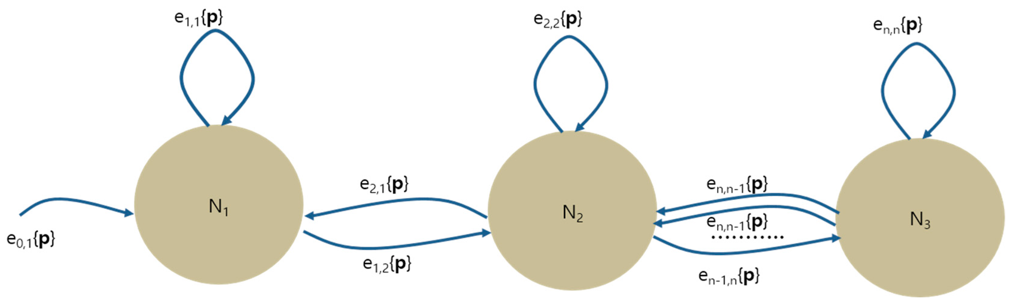
At a high level, modeling of the house is designed on a conceptual modeling graph data structure. By using the modeling graph, we are able to break down the whole house into several components and explain the geometrical connection between them. In a modeling graph, the nodes are specific components of a house such as a base, a body or a roof. The edges on the graph, which are represented as direct arrows, represent the connection between the components. The extensibility is one of the benefits of the modeling graph technique. By adding nodes with edges on the existing graph, we can make more complicated house model. Figure 2 shows the general modeling graph. In this modeling graph, nodes are represented as and edges are represented as where i and j are incoming and out-going nodes respectively and p is a set of parameters for constructing the out-going nodes. The parameter includes the 3D offset between two connected nodes and all parameters required numerical values such as types or sizes for specifying a particular shape of the component.
There are two important features in the modeling graph. First, as we can see in the right side of Figure 2, two nodes are allowed to be connected with multiple directed edges. The edges may connect the same components, but they have a different set of parameters. It means that even if we visit the same node repeatedly, we are able to create different shapes, depending on which edge the algorithm chooses. Second, our modeling graph allows self-edges. The self-edges are used to model the same component repetitively. Again, there might be several self-edges for a same node. This provides an ability to construct similar but different styles of component multiple times.
At the runtime, the modeling is processed by traversing the graph from the starting node to the end node. When the algorithm transits from one node to the other, it applies the parameters set contained in the edge.
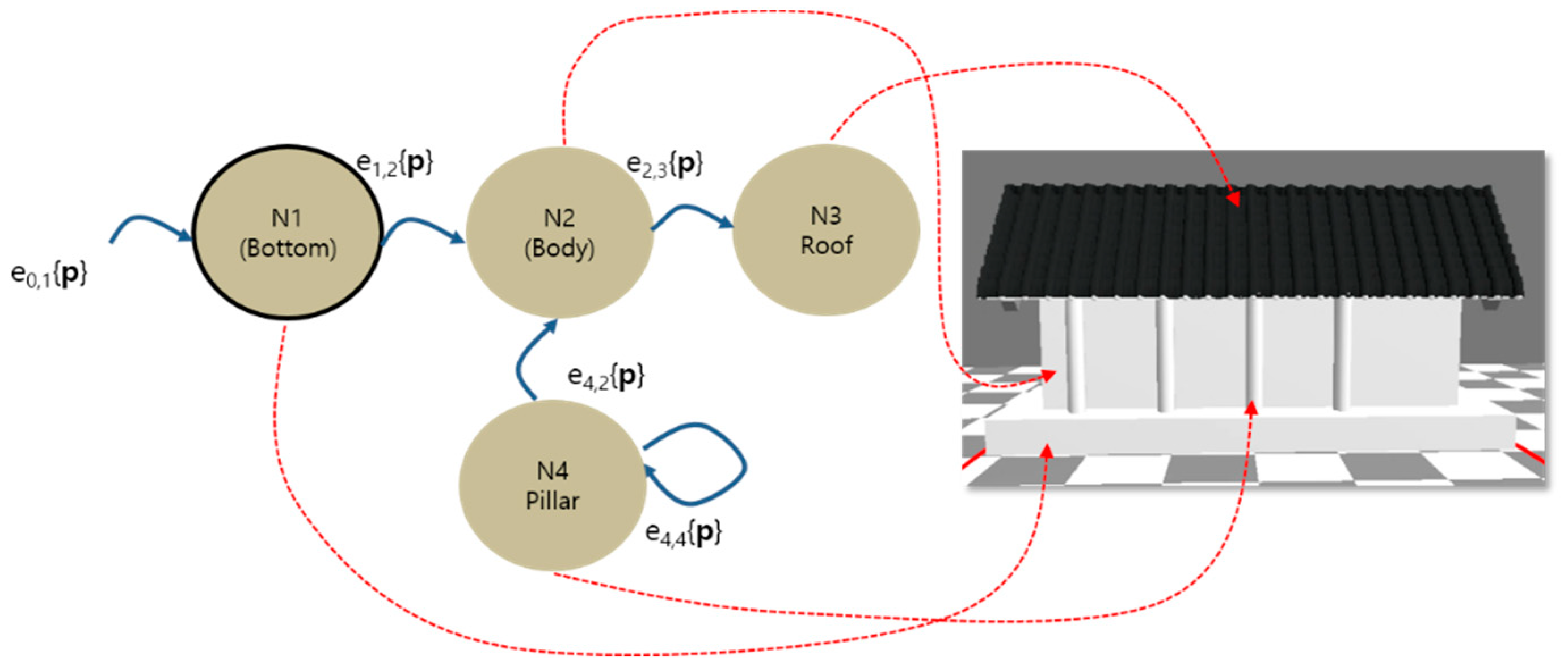
Figure 3 shows an example of the modeling graph and its result after a traversal. The sample giwa house has four major components which are bottom, body, pillars and roof, and the bottom node is the starting node. In this graph, the bottom node is connected with the body node, and the body node is connected with the roof node. Afterwards, the body node is connected with another pillar node. In particular, the four pillars of the house are added to the central body through four self-edges on the pillar node of the modeling graph.
Extensibility is the main advantage of the modeling graph. By adding nodes and edges, we are able to construct the architecture in a scalable manner. Figure 4 indicates the addition of pillars on the lower part of house by adding edges on the graph. In this case, two nodes, which are the pillar node and the lower body node, are connected with multiple edges. Each edge has a different set of parameters including 3D offset vectors. By selecting a particular edge, we are able to put the pillar on the particular position.
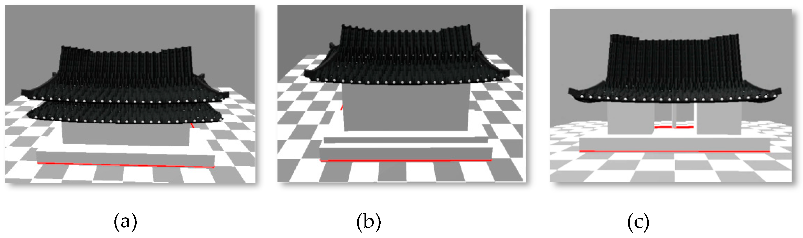
Figure 5 indicates the variability of houses made by the modeling graph. This example applies self-edges, which is one of novel features of this modeling technique. Figure 5a shows a giwa house designed by repetition of a roof component. Figure 5b shows a house with double bottom components. Figure 5c shows a house with two body components. As shown in these figures, even though we repeat the same node of the graph several times, we can construct different styles by using a different parameter set.
3.2. Cardinal Spline
One of the important features of Korean giwa houses is their beautiful curved shape of roofs. To achieve the curved silhouette, we apply the Cardinal spline with a set of control points. The curve acts as a guideline to add a series of giwa, which is a tile block of roof, along the curve. Among many different spline curves, we chose the Cardinal spline because it is an interpolation spline. The interpolation spline is quite useful for procedural modeling because the curve always passes through the control points. The Cardinal spline is made of segments where each segment is defined by means of four control points but only goes from the second point to the third one. Mathematically, given four control points from to for a segment, the position at parameter t, denoted as , can be calculated as the following equation.
where s is the tension value and . The tangent at parameter t, , also can be calculated as follows:
Designing a long curve can be easily done by adding more control points on the curve. A four- pairwise control set, where some of control points are repeated from the previous curve segment, is able to create a new segment that is smoothly extended from the previous segment.
3.3. Parameterziation of Three Different Giwa Houses
One of the prominent characteristics of Korean traditional houses is that no roofs are flat. Almost all of them have curved lines and surfaces, which is one of the unique originalities of Korean architecture [4,21]. Also, because the roof structures are quite symmetrical, if we define one front side of the roof, then the rear side is automatically designed by calculating the reflection. The overall shape of roof is designed by the Cardinal spline curve that we explained in Section 3.1.
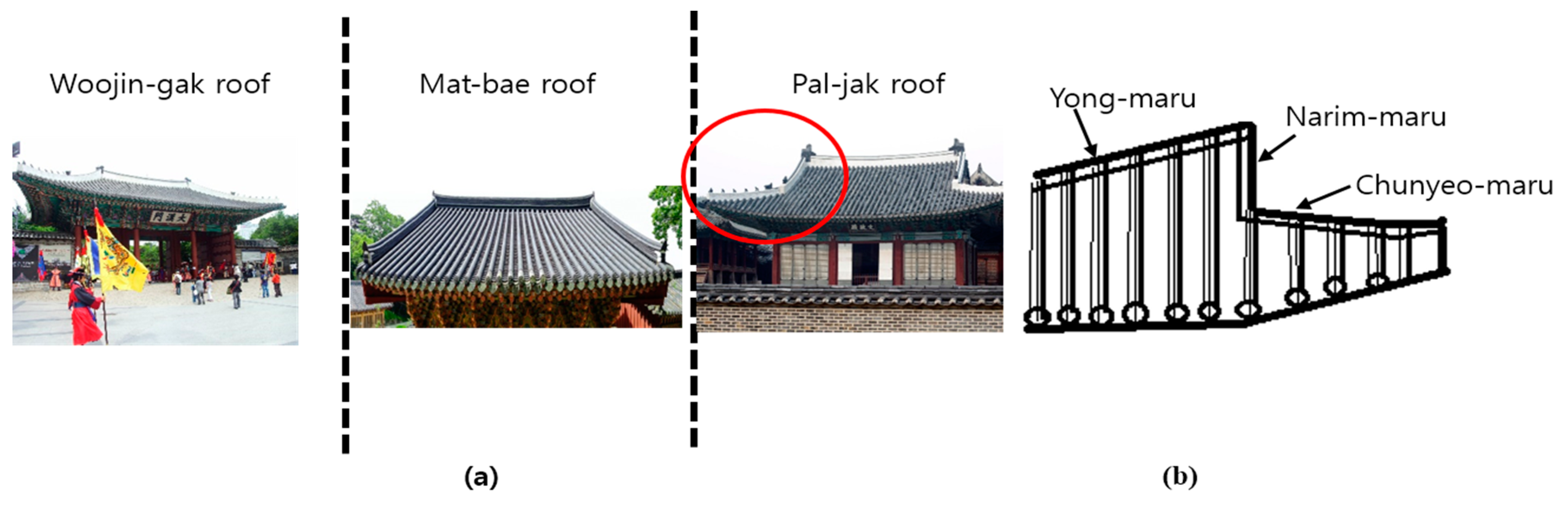
In this section, we aim to parameterize three most popular Korean roof styles in a procedural way. These are Pal-jak, Mat-bae and Woojin-gak. Figure 6a shows those roof styles, respectively. In general, giwa roofs are supported by three big beams: yong-maru, narim-maru and chenyo-maru as shown in Figure 6b. The Yong-maru is the horizontal beam that is located on the central part of the roof. It supports the whole roof. The Narim-maru is the vertical beam at both ends of the Yong-maru, and the Chunyeo-maru is the beam around the edge of the roof outside.
Depending on the roof type, some beams are not needed. For example, Mat-bae roof does not need Chunyeo-maru. When we parameterize such roof style, we need to take that into account.
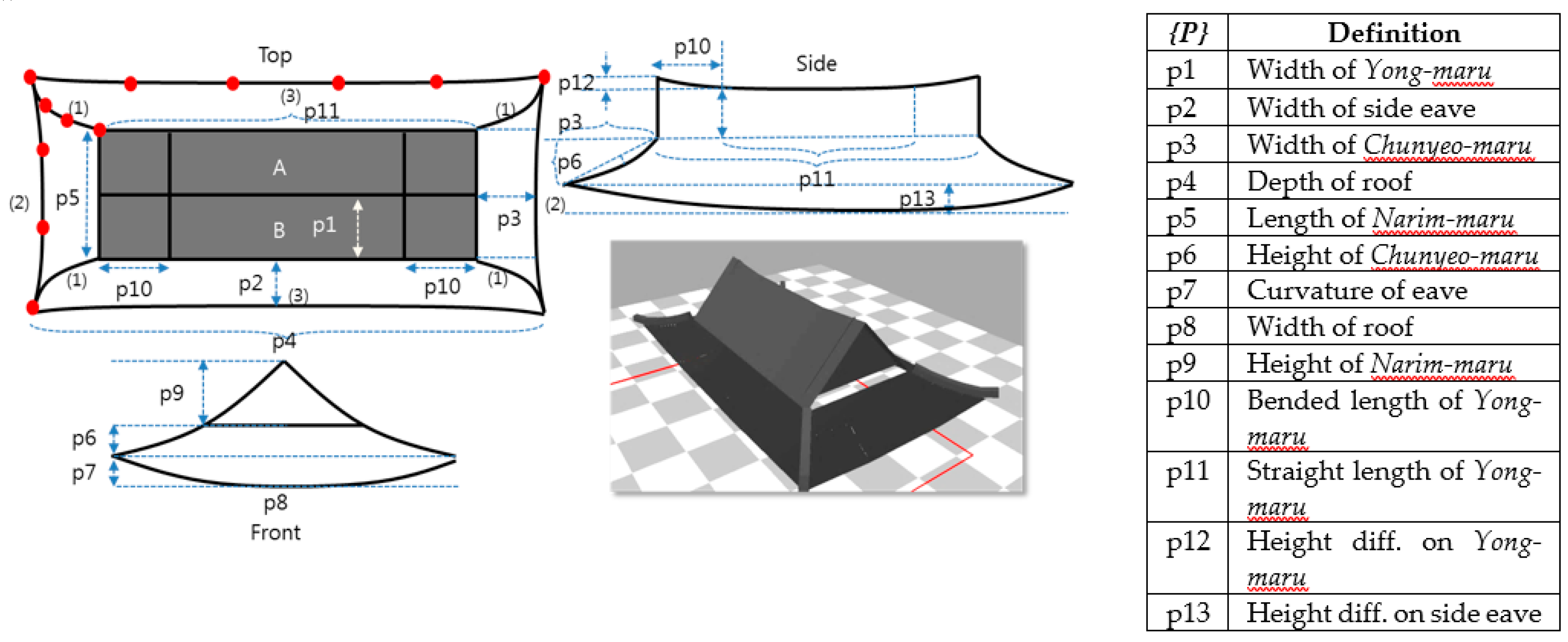
3.3.1. Pal-Jak Roof
The most beautiful and complicated roof style is Pal-jak. As you can see on the left side of Figure 6, the side of Pal-jak roof looks like the Chinese letter eight (八). This makes its overall appearance very majestic and solemn. However, the most important characteristic of the Pal-jak roof is that three beams are attached to the roof, as illustrated in Figure 7. To build the 3D model of the roof, we first need to design the outline through the Cardinal-spline curve. Figure 7 shows the top, front and side view of Pal-jak and some of the important parameters for the roof. Note that all blue dashed lines on the figure indicate the parameters for the roof and red dots represent some of the control points of the spline curves. Note that the picture on the bottom of Figure 7 shows the real Pal-jak roof rendered with our proposed rendering tool. As explained in Section 3.1, the whole roof component is represented as a single node in a modeling graph, and those parameters we extracted are entered on an edge of the graph.
To specify a silhouette of the roof, the cardinal spline requires at least four control points. If the curve is short, then four control points are sufficient. However, if it is too long, then we need to add more control points. In our approach, we set a threshold value to determine the number of control points.
Designing the roof outline follows the steps below:
Step 1. Given the size parameters in x, y and z axes for the roof and eave length, we design the central part of the roof (shaded area is noted as A and B) with two rectangles. The two rectangles look like a wedge ( ) on the front. Then, they are subdivided into three parts in z axis to have different heights.
Step 2. We specify four curves on each corner (curves are noted (1) in Figure 5). Positions of the first and end control points of the four curves can be set from the two rectangles from Step 1.
Step 3. We connect four ending positions of the curves from Step 2 with other curves. (Curves are noted as (2) and (3) in Figure 5.)
Step 4. We subdivide the curves of Step 2 into three segments vertically and horizontally, and repeat step 3 on the segments to get a set of quads. (center of Figure 5)
The curvatures of the curve are controlled by the y coordinate of control points located inside. After going through 4 steps above, we can have a set of quads as an output. Then, we can apply the automatic way of layering 3D giwa tiles on the quads. This process is explained in detail in Section 3.4.
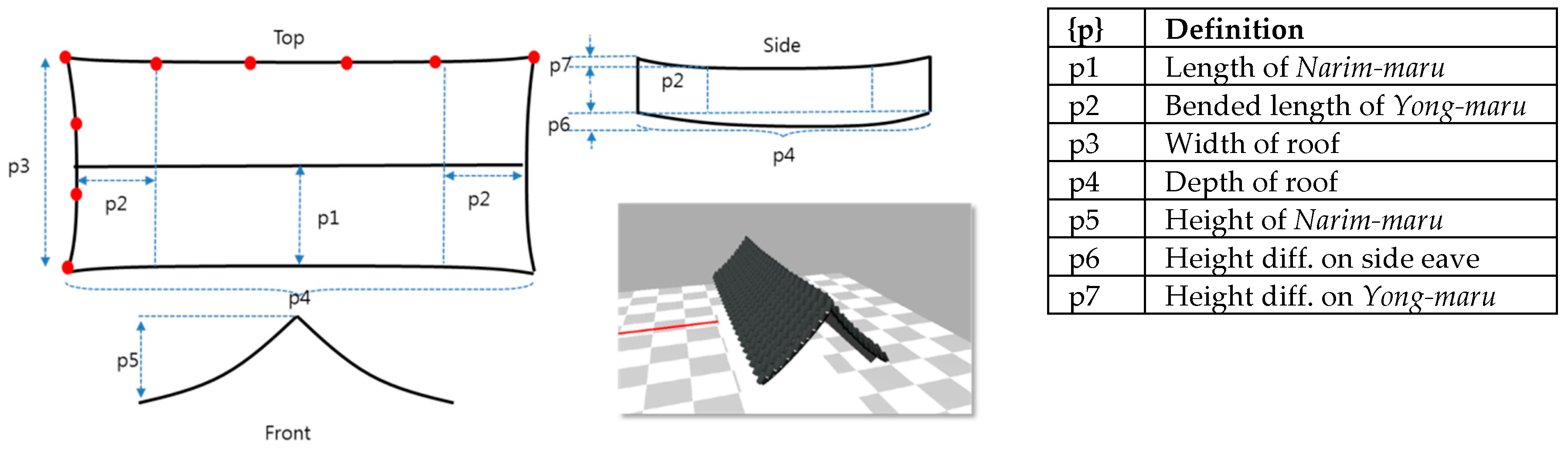
3.3.2. Mat-Bae Roof
The Mat-bae roof is a subset version of the Pal-jak roof which does not have Chunyeo-maru. By removing Chunyeo-maru on the front and back, we can easily design the Mat-bae roof from the Pal-jak roof. Figure 8 shows an example of Mat-bae roof and its important parameters (Blue dashed lines). Similar to the Pal-jak roof, thanks to spline curve specification, we are able to represent the beauty of curved roof shapes easily. Figure 8 shows all parameters associated with the Mat-bae roof and the actual rendered image obtained by our rendering tool.
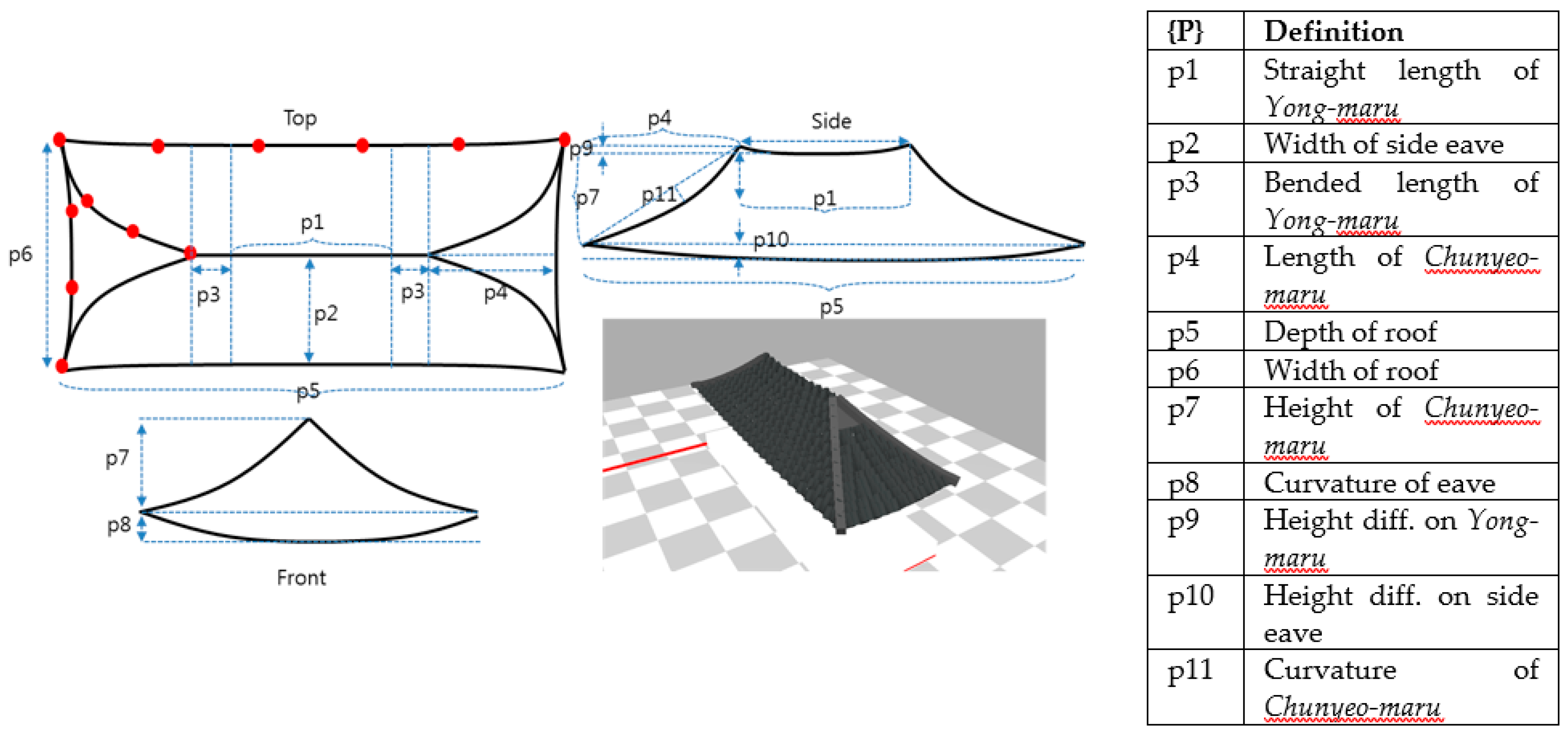
3.3.3. Mat-Bae Roof
The Woojin-gak roof is also a simplified version of the Pal-jak roof in which the Narim-maru does not exist. The front and rear parts of the roof look like a triangle, and the sides look like a trapezoid. Figure 9 shows the important parameters and the final shape of the Woojin-gak roof with its rendered image.
3.4. Automatic Layout of Giwa Tiles
One of the most important characteristics of Korean traditional giwa houses is that the entire surface of roofs is covered with tiles called ‘giwa’ [4]. For a realistic implementation of this giwa layering, the simplest solution is texture mapping, where we basically wrap the entire geometry with giwa images. However, because the image-based texture mapping makes it impossible to represent the architectural silhouette which is one of the most important features in 3D architecture modeling, we instead procedurally place real 3D giwa geometry on the roof. Figure 8 explains the layering process of giwa tiles. Note that we use bolt font to represent vectors.
When we lay out the whole set of giwa tiles on the roof, we must align them in a single direction. Also, because the polygons that are compositing the roof can form a random shape in some cases, we must control the number of giwa tiles for the polygon and adjust the gap between tiles without causing any visual discontinuity. Without loss of generality, we assume that the plane of the roof is comprised of a set of quadrilaterals, which is true for most Korean giwa houses [21].
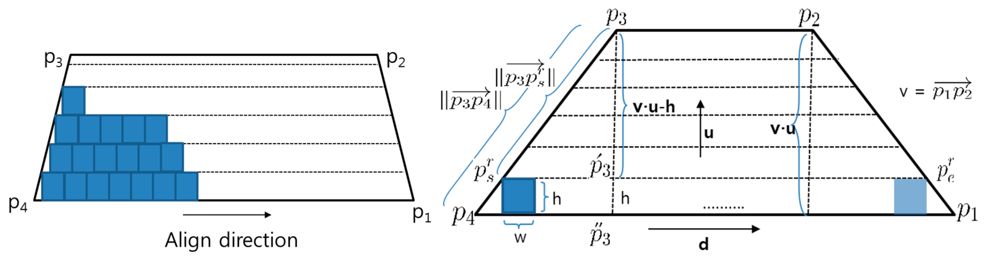
Given a quadrilateral plane defined by four vertices , where vector and vector are parallel, the algorithm first finds a 3D normal vector, , of the plane by calculating cross product of two vectors and . Then, from the align vector entered by the user, the up vector u can be easily found through the cross product . Those vectors and vertices are shown in Figure 10.
Our basic idea is that we layer the giwa blocks one row at a time until we cover the entire rectangle polygon. The number of rows of tiles, , for the polygon, can be calculated as ) where u is the unit up vector, , h is the height of a single giwa tile and the operator represent the dot product. The int() converts from a real number to an integer value.
If we know , then the next step is to find the starting position of layering, , and ending position , for the row r. Figure 10 shows the position of and for the last row in which the blue squares represent giwa tiles. To find the position of , we use the proportional property between two similar right triangles and which are formed by three points , , and , respectively. Note that the points and are always on the line of up vector u in our formulation. Because the two similar right-angled triangles and have proportional edge lengths and against and , the length of vector can be computed through the following equation:
where h is the height of a single giwa tile, and u is the up vector.
From the length of vector , we can calculate the position of . By applying similar way to the other side, we can get the on the right side. If we know the and , the number of giwa tiles for row r, denoted as , can be estimated by where w is the width of a single giwa. However, because the distance between and is not an exact multiple of fixed width w, there might be some space left or some tiles may pass through at the end of the row. In order to fix this problem, our algorithm automatically calculates gaps between tiles for each row so that the last position of giwa would match the exactly. The gap between adjacent tile j and j+1 in row r, say , can be calculated through the following equation:
where w is the width of the single giwa and is the number of giwa tiles for row r.
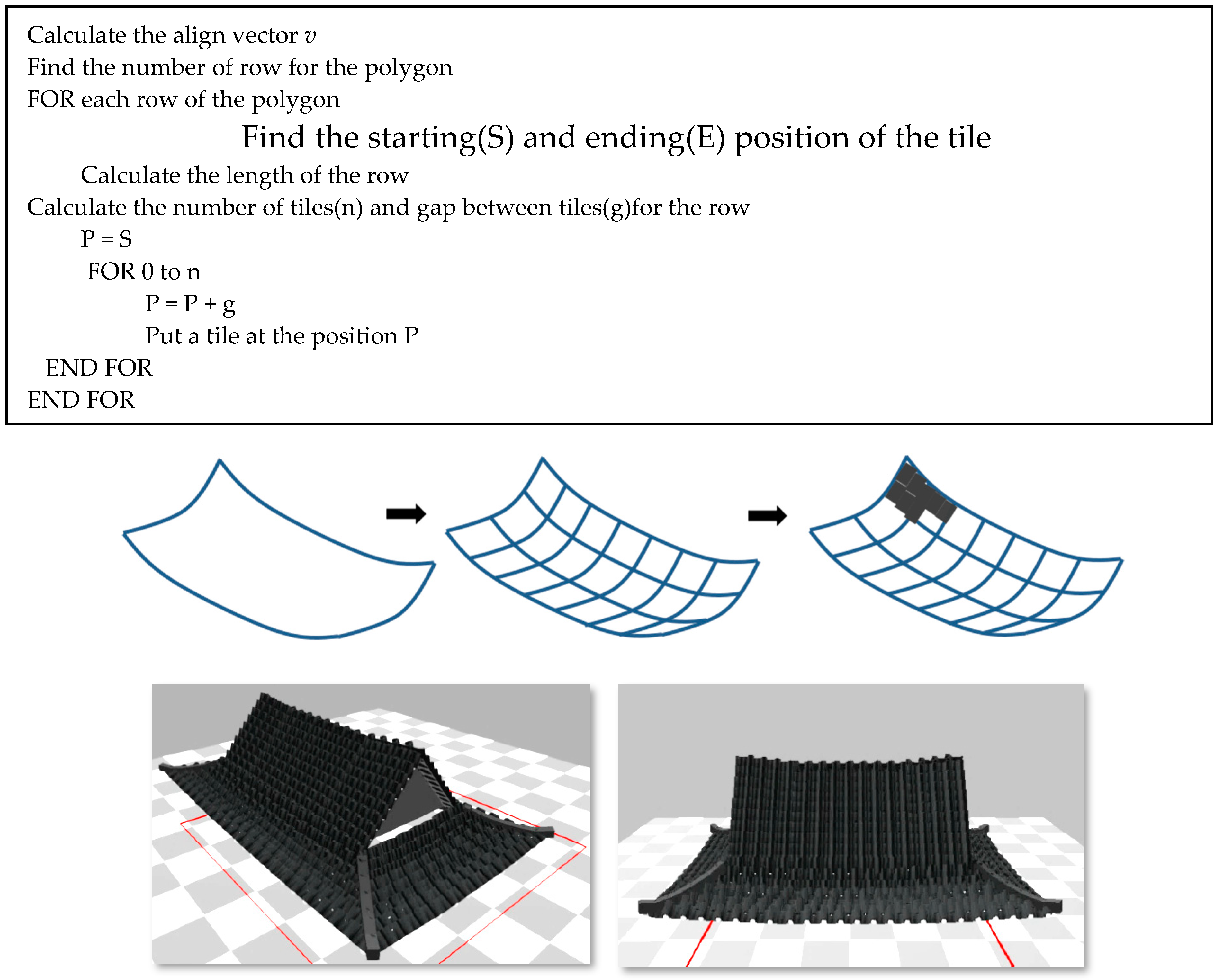
From the , the position of ith giwa, , is then computed as . At rendering time, we draw a single giwa at and repeat this until equals . Once we finish one row, we move up to the next row and reiterate the same process until we fill out the entire polygon. We summarize the layering algorithm in the box below. Figure 11 shows the result that we get from applying our algorithm to the Pal-jak roof.
4. Experiments
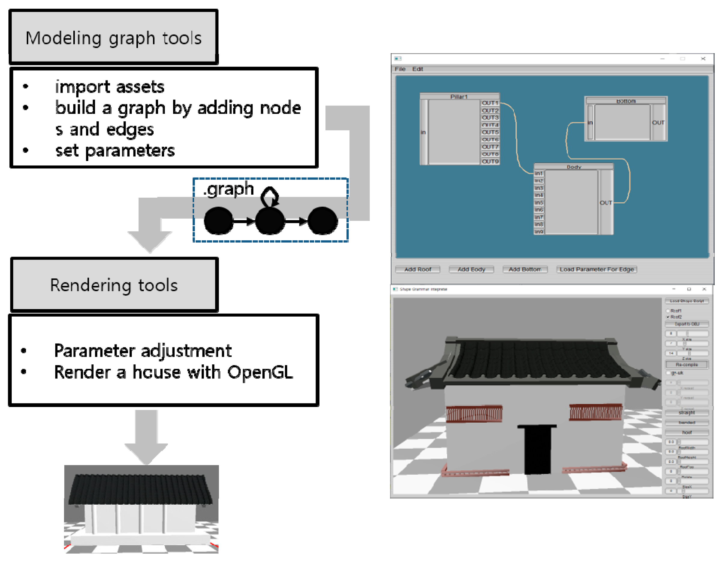
To verify the proposed procedural modeling technique, we implemented a software prototype system in the Microsoft Windows 10 platform. The PC hardware setup for experiments included an Intel i-7 CPU with 8G main memory and Nvidia 1060 as a graphics acceleration card. The developed system consisted of two software tools. The first tool is the high-level modeling graph creation tool that generated a modeling graph through user-friendly GUI (Graphical User Interface). The right picture of Figure 12 showed the modeling graph tools. The second tool is the rendering tool that renders a building by traversing the graph obtained from the modeling graph tool. The GUI library that we used for our tools was the open-source FLTK (FastLight ToolKit). The library was used for both tools to create windows, buttons, slider bars, nodes and edges of a graph. For rendering 3D architecture, we used the standard OpenGL functions which is already in Microsoft Windows by default. Figure 10 shows the overall steps of building giwa houses through the tools. Note that the right picture of Figure 12 shows the screenshot of actual tools that we built. At first, we were able to create a modeling graph by using the modeling graph tool. Through the tool, users are able to generate nodes of the graph by pressing buttons, and link them with edges by simply dragging the mouse.
Once we built a graph, then the parameters that attached on a particular edge and the whole structure of nodes and edge are written as a simple text file. The text script file, whose extension is denoted as graph, is then used as an input to the real time rendering tool at the next stage. After reading a script file, the rendering subsystem constructs a modeling graph internally and starts to traverse the graph to build a giwa house. Finally, the house is rendered and shown on the screen.
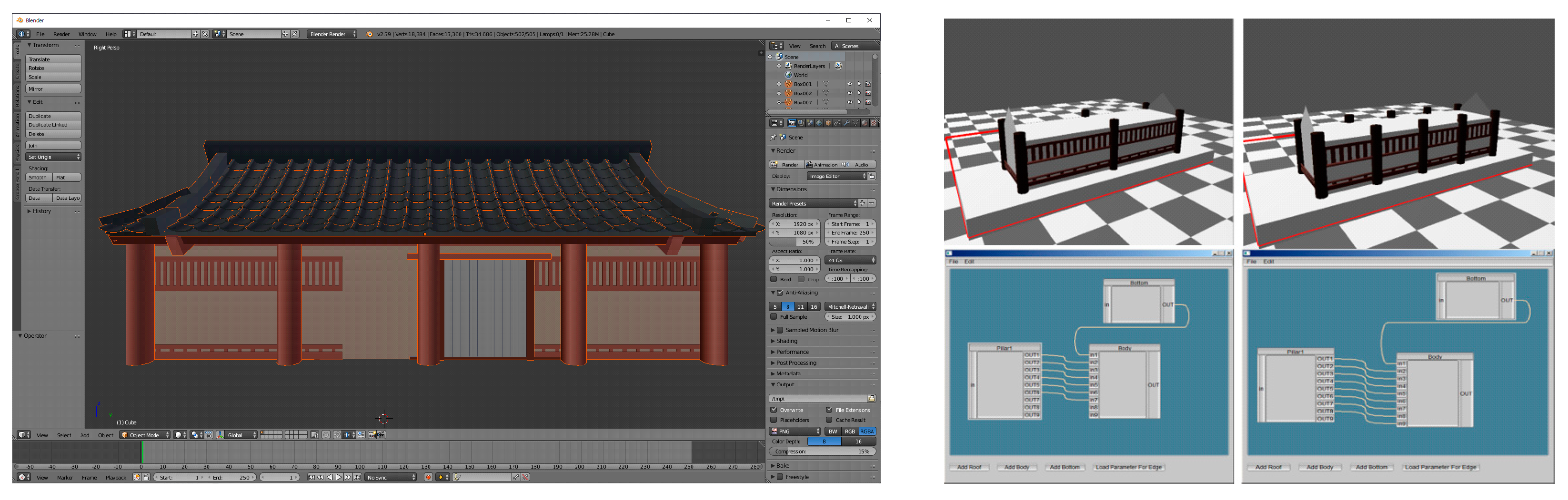
In order to check how much time was needed for constructing and modeling giwa houses, we hired a student who could use the general free 3D graphics software, blender, and asked him to build a house with the tool. For fairness, the student was given a set of components for the house. All he was doing was building the house by assembling the component. Since the tool did not support the procedural scripts, he had to assemble the house by putting the components at the exact positions manually using the mouse. Then, we asked him to build the same house with our proposed tool. When he used our tool, he had to change the values of parameters such as 3D distance between components manually through a user interface. We repeated the experiment 5 times and checked the average time needed to build the house. Figure 13 showed the screenshots of the two tools and Table 1 represented the average times when users used those tools. Our experiment showed that it took around ¼ times less time when he used our tool.
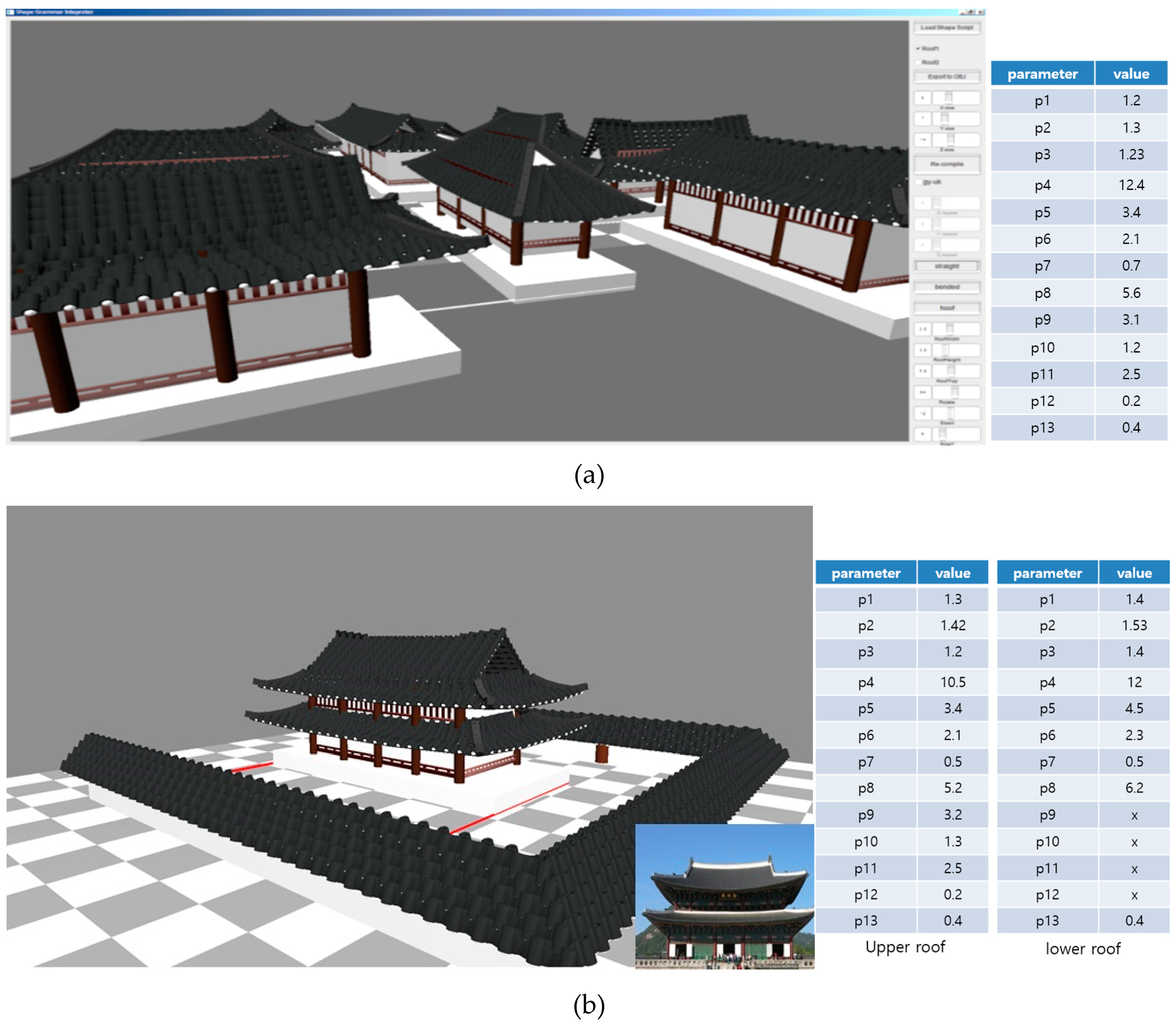
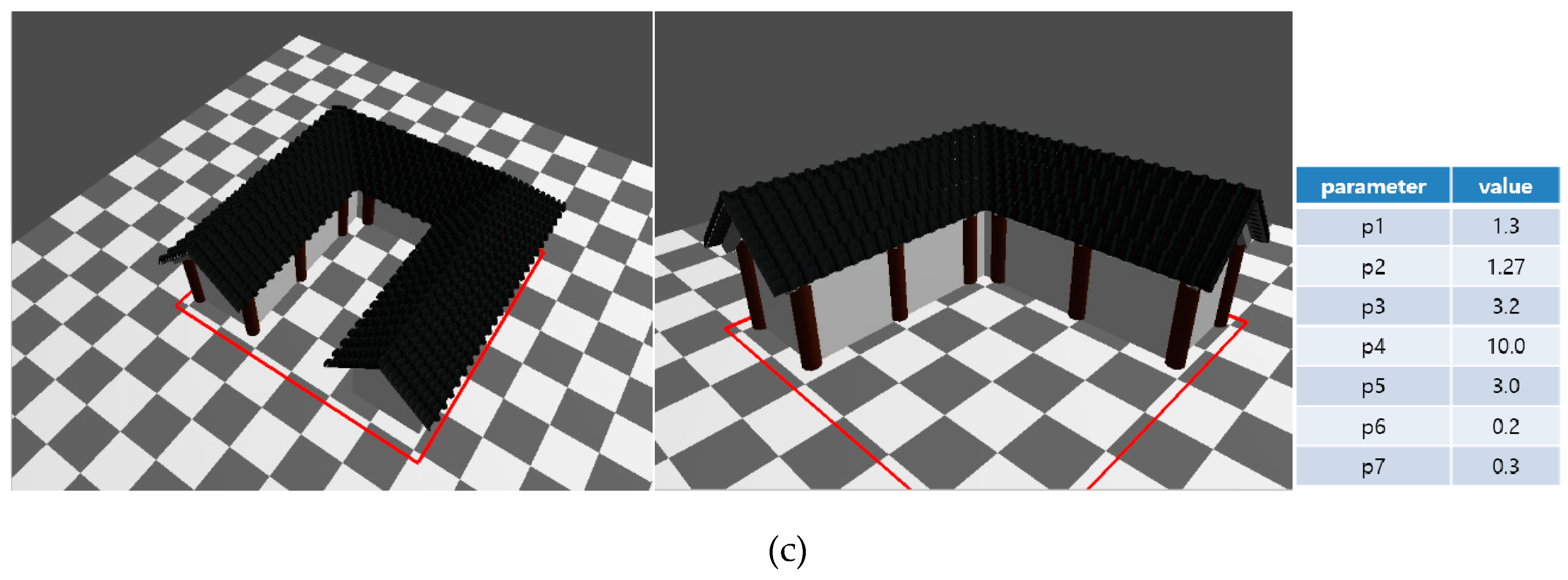
Figure 14 shows some of the 3D Korean giwa house models constructed by using the software with parameters. After completion of the giwa house, all the parameters were shown on the panel of the right side of window. The user was allowed to change or modify the parameters through the user interface. These modified parameters were immediately reflected on the rendered window on the left side so that the user could check whether or not their parameters were correct. The top of Figure 14 shows an ancient Korean traditional village rendered by our rendering subsystem. The walls in the picture were also modeled by the same software. The rendering time for each house took less than 0.1 second once we finished all parameter tuning. The middle picture of Figure 14 is a typical Korean palace which has double Pal-jak roofs and associated parameters. For comparison, we attached a real picture of a royal palace on the right side. The house with dual or triple roofs was modeled easily by just adding self-edges to the modeling graph. Finally, the bottom picture of Figure 14 shows two houses with L shapes and square bracket shapes, respectively. As we did in the dual roof of royal palace, I-shape of house can be repeated multiple times with different positon and orientation parameter to construct those house shapes. This verified the scalability and extensibility of our algorithm. Note that the bended part of the roof did not have any visual discontinuity because the entire roof was designed precisely by our algorithm.
5. Conclusions
This paper introduces a procedural modeling algorithm for Korean traditional giwa houses. At the high level, we propose a data structure called a ‘modeling graph’ to represent the relations between components of the houses. In a graph, nodes represent particular components of the house while edges represent geometrical connection between two components with associated parameters. Once we built a modeling graph, it went through the rendering tool where a house is rendered by traversing the graph from the starting node to the ending. Unlike other scene graph-based approaches, the proposed modeling graph allowed multiple edges between two nodes and self-edges on a single node. This feature provides more variability and extensibility on the architecture modeling than other approaches do.
At the low level, we formulate the three widely used Korean traditional roof structures for giwa houses, which are Pal-jak, Mat-bae and Woojin-gak, and we came up with list of all required parameters. Those structures preserve the original beauty of traditional curved roofs by applying the Cardinal spline curve technique on the silhouette of the roof. In addition, we propose a mathematical formula to lay out the real 3D giwa tiles on the roof to simulate the silhouette of real houses as closely as possible.
One limitation of our approach is an ignorance of fine details of houses. Although we parameterize three different roof styles of giwa house, there could be more finely detailed parameters. In a real giwa house, there are many ornamental parts in the roof and body, which we ignored for simplification. We would like to add more details in the future. Also, we would like to extend our approach to the chogo-house, which is another common architecture for people with lower levels of social status. From the implementation point of view, we used simple text files to store all parameters. For better management of parameters, we would like to use more standard XML or JSON files instead in the future.
Although we addressed the problem of building Korean traditional houses with a computer graphics technique, we believe that this technique is general enough to build other East Asian architecture, including Japanese and Chinese traditional houses. As shown in the book [1], even though detailed ornamental parts are different from country to country, the overall shapes of house have many similarities across these three countries. This is because Chinese culture has influenced Korean and Japanese cultures for thousands of years. In the future, we would like to extract all required parameters for general East Asian architecture.
Funding
This research received no external funding.
Conflicts of Interest
The author declares no conflict of interest.
References
- Norwich, J.J. Greate Architecture of the World; Bonanza Books; Da Capo Press: Cambridge, MA, USA, 1975. [Google Scholar]
- Kim, D. The natural environment control system of Korean traditional architecture: Comparison with Korean contemporary architecture. Build. Environ. 2006, 41, 1905–1912. [Google Scholar] [CrossRef]
- Kim, B.; Lee, J. A study of the Ondol (Gudul, Floor Heating System) and Kitchen Space in the Traditional Houses in Jeju Island. Int. J. Hum. Ecol. 2003, 4, 15–23. [Google Scholar]
- Wikipedia. Available online: http://en.wikipedia.org/wiki/Hanok (accessed on 19 February 2019).
- Guidi, G.; Barsanti, S.G.; Micoli, L.L.; Ruseo, M. Massive 3D digitization of Museum Contents. Built Heritage: Monitoring Conservation Management Research for Development; Springer: Berlin, Germany, 2015; pp. 335–346. [Google Scholar]
- Masi, A.D. Smart Cultural Heritage and Open Source as Regeneration of Historical Centers: Fruition, Conservation and Preservation in Current Methods of 2D/3D Digitization and 3D modeling. In Proceedings of the IEEE Fourth International Conference on Big Data and Cloud Computing, Sydney, Australia, 3–5 December 2014; pp. 729–736. [Google Scholar]
- Autodesk. Available online: https://www.autodesk.com/products (accessed on 2 March 2019).
- Jackson, B.; Koehler, R. Korean Architecture: Breathing with Nature; Seoul Selection: Seoul, Korea, 2015. [Google Scholar]
- Liu, H.; Wang, Q.; Hua, W.; Zhou, D.; Bao, H. Building Chinese Ancient Architectures in Seconds. In Proceedings of the International Conference on Computational Science, Workshop on Computer Graphics and Geometric Modeling, Atlanta, GA, USA, 22–25 May 2005; pp. 248–255. [Google Scholar]
- Shiry, P.; Ashikhmin, M.; Marschner, S. Fundamental of Computer Graphics; CRC Press: Boca Raton, FL, USA, 2009. [Google Scholar]
- Wonka, P.; Wimmer, M.; Sillion, F.; Ribarsky, W. Instant Architecture; ACM Transactions on Graphics: New York, NY, USA, 2003. [Google Scholar]
- Josie, W. Inventor Mentor: Programming Object-Oriented 3D Graphics with Open Inventor; Addison-Wesley: Boston, MA, USA, 1994. [Google Scholar]
- Prusinkiewicz, P.; Lindenmayer, L. The Algorithmic Beauty of Plants; Springer-Verlag: Berlin, Germany, 1990. [Google Scholar]
- Birch, P.J.; Browne, S.P.; Jennings, V.J.; Day, A.M.; Arnold, D.B. Rapid Procedural-Modeling of Architectural structure. In Proceedings of the 2001 Conferences on Virtual Reality, Archeology and Cultural Heritage, Glyfada, Greece, 28–30 November 2001; pp. 187–196. [Google Scholar]
- Venegas, C.; Aliaga, D.; Wonka, P.; Muller, P.; Waddell, P.; Watson, P. Modeling the Appearance and Behaviors of Urban Spaces. Comput. Gr. Forum 2010, 29, 25–42. [Google Scholar] [CrossRef]
- Houdini. Available online: https://www.sidefx.com/ (accessed on 2 March 2019).
- Müeller, P.; Wonka, P.; Haegler, S.; Ulmer, A.; Gool, V.L. Procedural Modeling of Buildings. ACM Trans. Gr. 2006, 25, 614–623. [Google Scholar] [CrossRef]
- Müller, O.; Vereenooghe, T.; Wonka, P.; Paap, I.; Gool, L.V. Procedural 3D Reconstruction of Puuc Buildings in Xkipchĕ. In Proceedings of the International Symposium on IEEE Virtual Reality, Alexsandria, VA, USA, 25 March 2006. [Google Scholar]
- Haegler, S.; Müller, P.; van Gool, L. Procedural Modeling for Digital Cultural Heritage. EURASIP J. Image Video Process. 2009, 1, 852392. [Google Scholar] [CrossRef]
- City Engine. Available online: http://www.esri.com/software/cityengine (accessed on 2 March 2019).
- Teoh, S.T. Generalized Descriptions for the Procedural Modeling of Ancient East Asian Buildings. In Proceedings of the Computational Aesthetics in Graphics, Visualization and Imaging, Victoria, BC, Canada, 28–30 May 2009. [Google Scholar]
- The Layout of a Hanok; Korean Tourism Organization: Wonju, Korea, 2013.
Figure 1.
(a) Comparison between the original scene graph [12]; (b) our proposed modeling graph
Figure 1.
(a) Comparison between the original scene graph [12]; (b) our proposed modeling graph

Figure 2.
A general modeling graph.

Figure 3.
An example of the modeling graph and its result.

Figure 4.
Extensibility of modeling graph: Our modeling graph allow multiple edges between two nodes. In this example, by putting several edges between pillar and lower body of house, we are able to put several pillars on the house. Note that each edge has different parameters. Therefore, we can put pillars at different positions.

Figure 5.
Variability of modeling graph: Since our graph allows self-edges, we can easily repeat the same components multiple times. (a) We repeated the Roof component so that it has dual roofs. (b) The Bottom component is repeated. (c) The Body component is repeated so that it has a hole in the middle.

Figure 6.
Korean traditional roof types: (a) Three different roof types (b) Three beams supporting the roof.
Figure 6.
Korean traditional roof types: (a) Three different roof types (b) Three beams supporting the roof.

Figure 7.
The Pal-Jak roof structure and a rendered picture obtained by our tool.

Figure 8.
The Mat-Bae roof structure and a rendered picture obtained by our tool.

Figure 9.
The Woojin-Gak roof structure and a rendered picture obtained by our tool.

Figure 10.
A polygon with four vertices and layout of giwa.

Figure 11.
Automatic Layout of Giwa Tiles on the Pal-Jak Roof.

Figure 12.
Overview of designing a giwa house through proposed software tools.

Figure 13.
(Left): A screenshot of blender for constructing a giwa house. (Right): GUI of modeling graph tools with rendered results.
Figure 13.
(Left): A screenshot of blender for constructing a giwa house. (Right): GUI of modeling graph tools with rendered results.

Figure 14.
(a) A screenshot of rendering tool. (b): A palace, designed and rendered by our system. (c): L and square bracket style of giwa house. The roof was designed by a Mat-Bae roof.
Figure 14.
(a) A screenshot of rendering tool. (b): A palace, designed and rendered by our system. (c): L and square bracket style of giwa house. The roof was designed by a Mat-Bae roof.


Table 1.
Average time comparison for building the giwa house.
| Tools | Average Time to Build | |
|---|---|---|
| Blender | 5.34 min | |
| Proposed tools | Modeling Graph Tool | 1.2 min |
| Rendering Tool | 10 sec |
© 2019 by the author. Licensee MDPI, Basel, Switzerland. This article is an open access article distributed under the terms and conditions of the Creative Commons Attribution (CC BY) license (http://creativecommons.org/licenses/by/4.0/).
Share and Cite
MDPI and ACS Style
Sung, M. Graph-Based Construction of 3D Korean Giwa House Models. Buildings 2019, 9, 68. https://doi.org/10.3390/buildings9030068
AMA Style
Sung M. Graph-Based Construction of 3D Korean Giwa House Models. Buildings. 2019; 9(3):68. https://doi.org/10.3390/buildings9030068
Chicago/Turabian StyleSung, Mankyu. 2019. "Graph-Based Construction of 3D Korean Giwa House Models" Buildings 9, no. 3: 68. https://doi.org/10.3390/buildings9030068
Note that from the first issue of 2016, this journal uses article numbers instead of page numbers. See further details here.