Article

On the Role of Acoustical Improvement and Surface Morphology of Seashell Composite Panel for Interior Applications in Buildings

1
Architecture Department, Engineering Faculty, Diponegoro University, Semarang 50275, Indonesia
2
Civil Engineering Department, Engineering Faculty, Diponegoro University, Semarang 50275, Indonesia
3
Environmental Engineering Department, Engineering Faculty, Diponegoro University, Semarang 50275, Indonesia
*
Author to whom correspondence should be addressed.
Buildings 2019, 9(3), 71; https://doi.org/10.3390/buildings9030071
Submission received: 6 March 2019 / Revised: 17 March 2019 / Accepted: 18 March 2019 / Published: 20 March 2019

Abstract

:
This manuscript focuses on the acoustical behaviors and surface morphology of seashell waste filler reinforced polyester (SFRP) coverings Anadara granosa Linn, Perna viridis Linn, and Placuna placenta Linn and applications in buildings. Their acoustical performances were observed using an impedance tube using a technique with two and four microphones based on ASTM E1050-98 and ASTM E2611-09. The improvements of acoustical performance were conducted by a coupled resonator inclusion with addition of a fibrous dacron layer and back cavity. The experimental results showed that the resonators and back cavity on the material structure were able to shift the absorption ability at low frequency. The promising wide broadband frequencies performance occurred when the 15 mm Placuna placenta FRP treated with front-tailed cavity without any additional fibrous layer and air gap started from 0.2 at 2.0 kHz. The combination of resonators and fibrous layer on the material structure was able to stabilize the sound transmission loss (STL) in 52–56 dB at a high frequency. On the observation of the simple surface morphology material, it was found that Placuna placenta Linn had the highest damping performances due to the smallest pores and the most carbon compound compared to the others. Therefore, this finding is very useful for building applications.

1. Introduction

Sustainability has become a recent issue in the global era. The building industry should integrate the efforts to sustain the environment among the challenges on climate change, ozone depletion and CO2 emission. One issue on the building material industry sector is of how to produce recycled materials [1,2]. Renewable Energy, material re-use and recycled material are the efforts being made in green building movements, meanwhile the use of recycled material should consider both economic and environmental aspects. Furthermore, the Green building movements provide considerable points for buildings that use recycled material. Some types of building materials that usually use recycled materials including concrete, wood, ceramics, and wall panels while the waste material that has often been used comes from natural resources such as wood waste, forests, and marine resources.
One of the abundant sea resources is seashells served for culinary business [3,4]. As those studies conducted by Setyowati et al. stated, that each culinary business using seashells in its menu could produce as much as thirty kilograms seashells as waste of the business process per day, so there are actually tons of shell waste produced by these culinary businesses [3,4]. Even more the seashells can be taken freely from coastal areas when there is a tide. The shells observed in this research are from three types of species namely Anadara granosa Linn (blood clams), Perna viridis Linn (green mussels), and Placuna placenta Linn (oyster) [3,
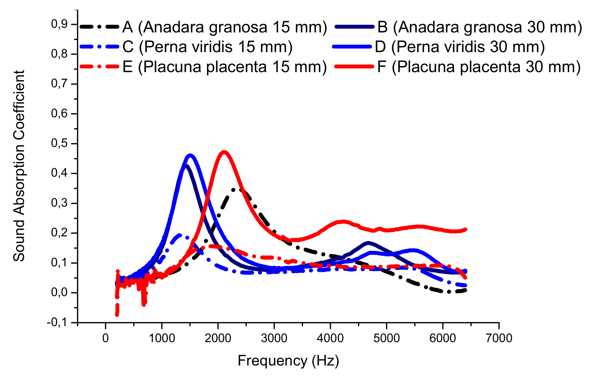
4]. In the previous research, it was reported that a polymeric composite having a thickness of 30 mm made of Placuna placenta Linn shell had a very good sound absorber performance with a peak at 0.47 on the medium frequency of 2.25 kHz. The polymeric composite from this species has a better ability to absorb sound in a wider frequency range than the other species [
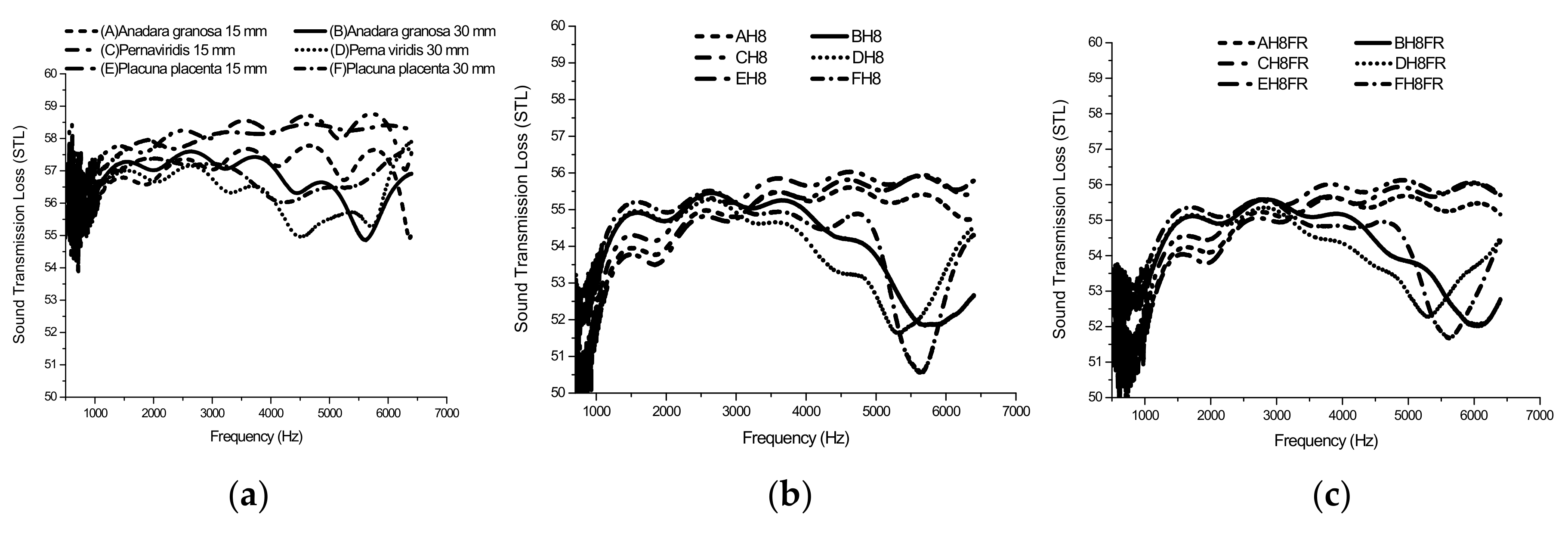
3]. Furthermore, the performance of transmission loss composite materials from this kind of shell ranges between 53 and 58 dB. The polymeric composite materials made of shells are good for both interior and exterior building materials [3].
The use of shell materials as diffusers and absorbers is possible, but they need treatment and improvement through additional resonators, coated fibrous panels, back cavities and any treatments such as those by Lee and Chen, Bravo et al. and Takahashi et al. in their studies [5,6,7]. Since it has the function as the protector of the mollusk the seashell is naturally tough. It containing cementeous compounds, minerals, is naturally hard, and has a good mechanical strength that is required for shelter purposes. The mechanical and chemical properties have been studied in various methods for many different purposes, including development of low strength materials, concrete, composites while also been used as biocomposite for dental applications. Research was conducted by Fombuena et al. and Odusanya et al., who studied seashell filler reinforced with unsaturated polyester (at 30 wt% and 10 wt% respectively) related to the flexural and hardness properties, but it did not consider the acoustical properties [8,9]. The results showed that the flexural strength, as well as the hardness and impact properties of the SFRP with 10 wt% seashell flour reinforcement, were largely improved. Research on seashell waste as a material was widely observed by Fombuena et al., Teixeira et al., and Li et al. [9,10,11], but most of the studies were not for an acoustical material.
As reported in the literature, seashells and mortar based composites are mostly hard and dense so are acoustically reflective. Further improvement is needed to get a higher performance especially for absorbing sound wave energy. This research discussed acoustical behavior improvements of seashell filler reinforced polyester which is a continuation and refinement of previous research on seashell concrete [3]. An experimental study referring to the ASTM E-1050 standard method was conducted on a 30 mm thickness polymeric composite by Setyowati et al. It found that composite containing Placuna placenta Linn powder as its raw material had a sound absorption coefficient of 0.47 for the frequency range above 2.25 kHz. This figure indicated a low performance with regard to the ability of controlling the high frequency noise. Continuing on, the applications of seashell waste in buildings were discussed in studies by Setyowati, et al. [12,13,14]. Further testing by using four microphone impedance tube techniques showed that the same sample had a sound transmission loss ranging from 53 dB to 58 dB with a spand frequency up to 6.3 kHz. Contrary to its sound absorption performance, it indicated the high ability on reducing energy of transmitted sound waves propagated through the material.
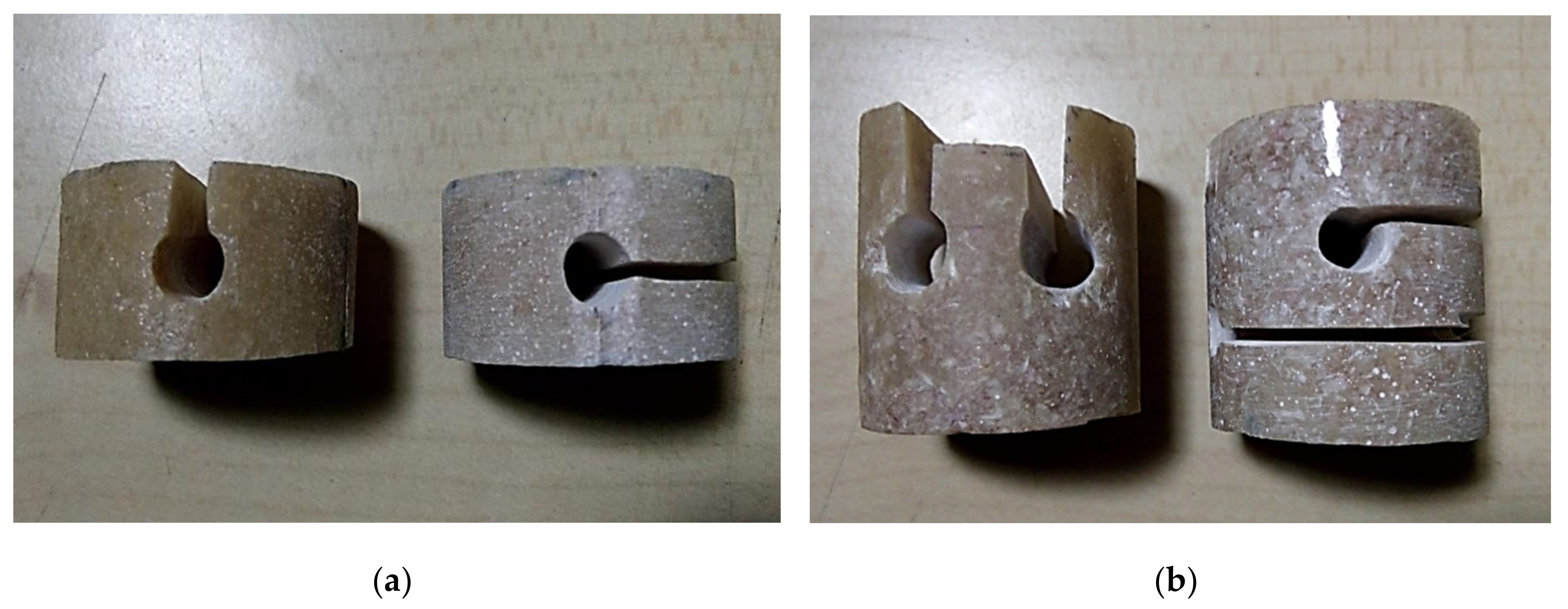
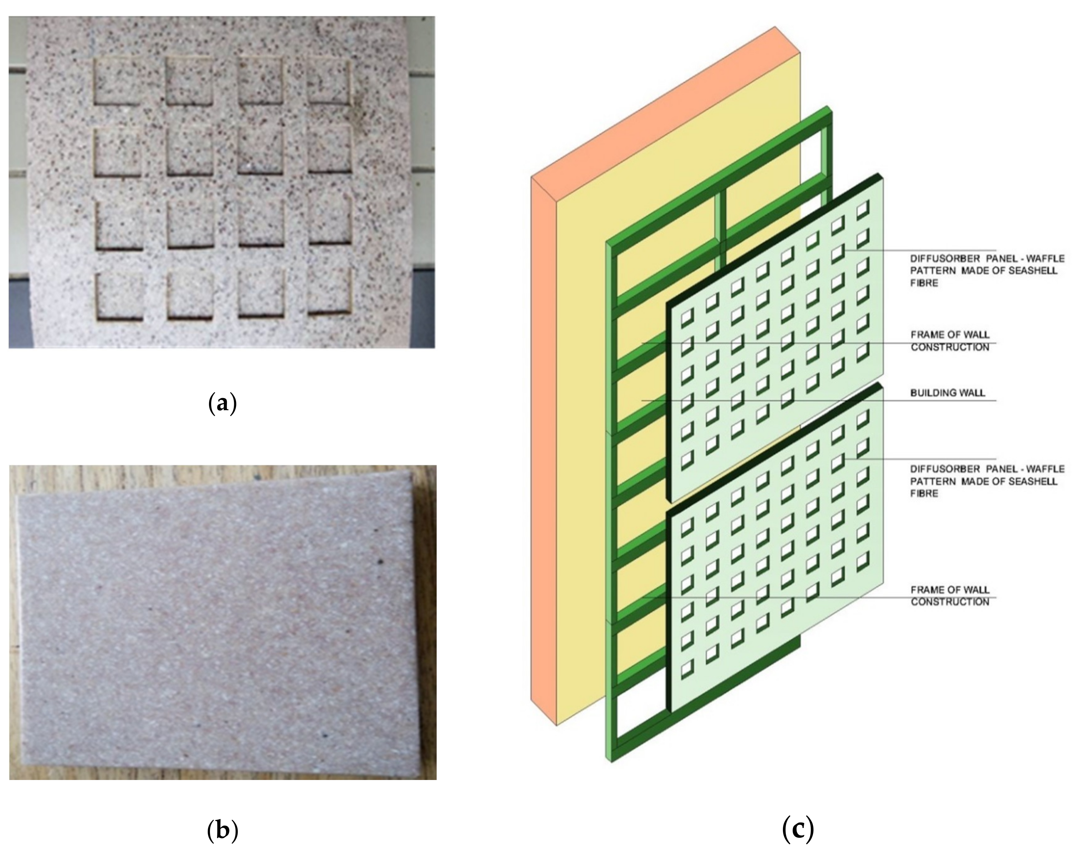
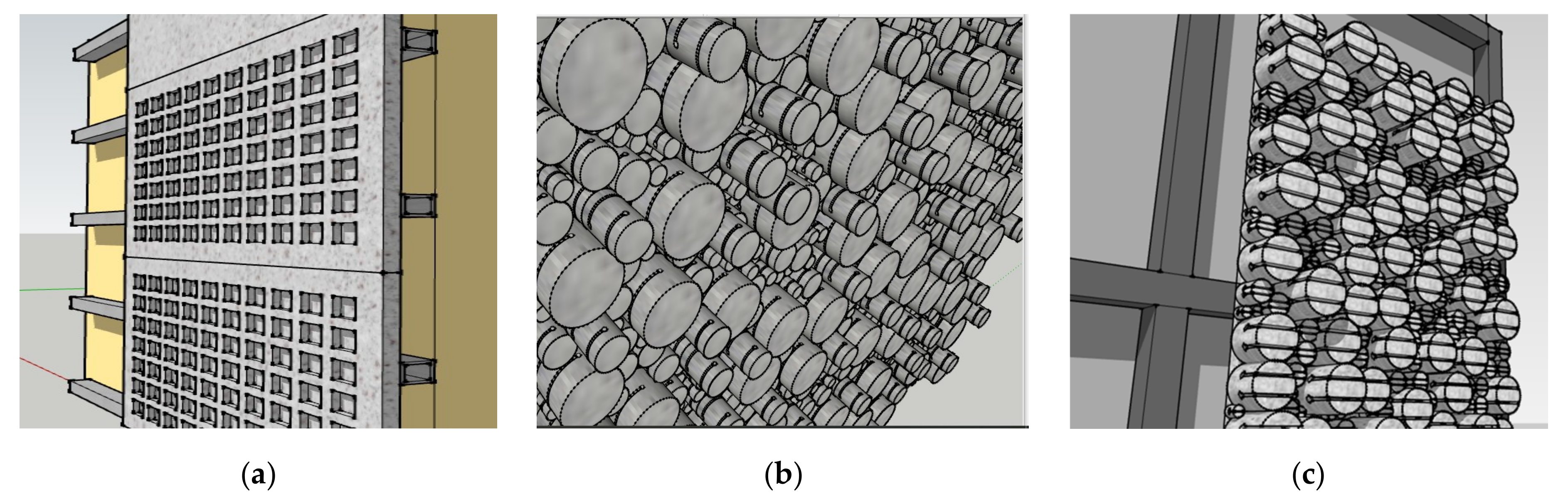
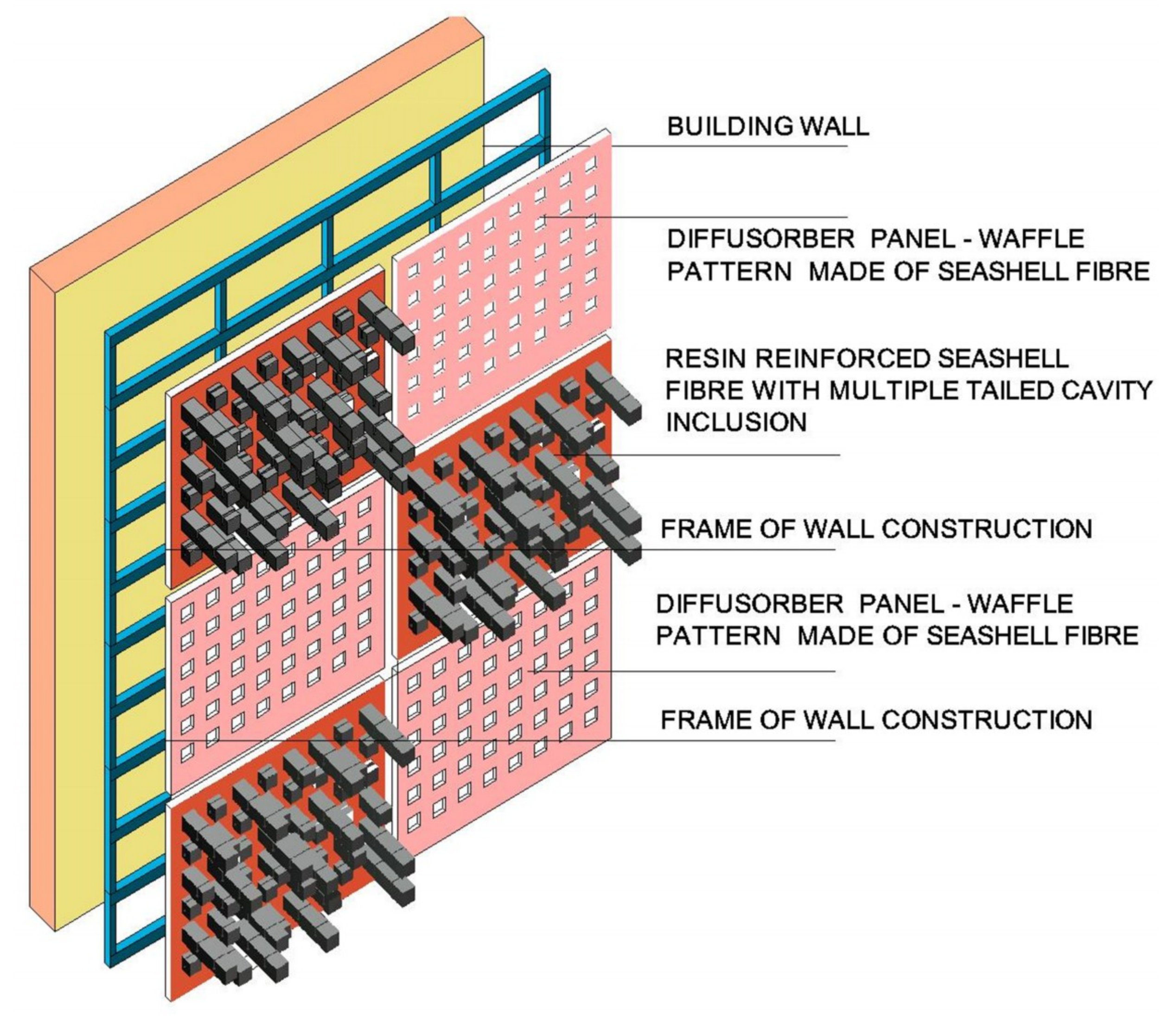
Unlike the topic of conventional porous and soft absorber materials, this research highlights non-porous material made of seashell waste composed of unsaturated polyester with treatment to improve the acoustical behavior associated with surface morphology, which has rarely been published elsewhere relating to acoustic-themed publications. Concerning an architectural term, this research described the application of SFRP panels with waffle texture, side-tailed cavity and front-tailed cavity in the final section of this paper. A surface modification technique is usually applied to improve the performance of sound silencers and sound diffusers. In relation to research purpose, the micro perforated plate (MPP) has been mostly used in many reports and publications such as studies conducted by Bravo et al. and Yahya et al. [6,15,16]. There are many approaches and techniques proposed by other researchers. Vigran and Meng et al. tried to fulfill the needs in acoustics, especially in the low frequency range. These examples involved the use of an MPP multi-layer with air banks between the layers [17,18]. A research on MPP also used a micro perforated panel called QRD (Quadratic Residue Diffuser). The QRD is a perforated panel combined with extended long-thin resonator tubes that could increase its acoustic performance to low and medium frequencies without changing the design of the panel [16]. The research of multiple-duct perforated tube resonators was also analyzed by Kar et al. related to the improvement of acoustic performances. The result was that this material could be used in commercial automotive mufflers [19]. Similar to the MPP, multi layer absorbers supported by the Helmholtz resonator and compartment cavities were developed by Ayub et al. and Kidner and Hansen [20,21]. The design of absorber is an approach that gives benefits not only in the absorption shift to a lower band, but also in improving MPP performance in the medium–high frequency range.
The behavior of sound waves touching the surface of a material experiences reflection, absorption, and the loss of sound due to the occurring viscous damping [19]. Sound absorption improvement is conducted as a noise control strategy in building components. In this research, an observation was made of the acoustical performance in seashell waste that was composed of polyester materials and catalysts. Some researchers conducted a material test on natural material composite shells, such as coconut shells and seashells, using a different method and approaches. Several researchers observed the thermal insulation and tensile strength of composite shell materials [8]. This research has a different approach because it combines the treatment of sound absorption improvement with the study of the surface morphology of the materials. On the other hand, some researchers observed the effective change of half wavelength to be the quarter wavelength that improves the acoustical performance of a material. The occurring viscous damping on the multilayer structure also has an effective role in improving sound absorption performance [5,16].
Moreover, the morphology of seashell based composite was also investigated since it has a strong relation with the density and its acoustic impedance. It determines the response of materials due to sound waves propagation and acoustical disturbances within. Many studies found that the density factor will affect the acoustic performance on both sound absorption and sound transmission loss. Acoustical response of wool board was reported by Hua and Enhui (2017) [22], while glass fiber and rockwool materials and high desinty bio-polymer foam (HDBP) were reported by Wang and Trong (2001) [23] and Latief et al (2014) [24] respectively. Another research by Nandanwar et al (2017) [25] showed that lower density fiber board posed a better sound absorption performance compared to similar board with a higher density. In regards to the use of cavity inclusion, Narang (1993) showed that the addition of a cavity to the metal frame could improve STL to the limit of 10 dB [26], while a similar result was reported by Ko et al (2007) who proposed that aluminum foam material could have high sound transmission loss if it was treated with the addition of a cavity to the structure [27]. The related reports on the acoustical properties of seashell based sound diffuser elements have rarely been published. So this research not only performed acoustic treatment but also described the application of SFRP panels as an acoustic component on the building.

2. Materials and Methods

The shell waste was obtained from the sea food culinary sector in the Java Province, particularly in the city of Semarang and its surrounding coastal regions. The waste was cleaned, separated based on species, and then thoroughly dried to get rid of all dampness. After drying for 3 days, the dry shells were ground using Hammer Mills. The next process was filtering the material with a 250 micron strainer in the Material and Acoustic Laboratory. The three kinds of ground shells, in the form of flour, were weighed using an electronic scale based on particle weight percentage. This flour mixture was then added to polyester resin composite. The improved polyester composite syntheses were divided into three variations based on the three species of seashells observed. The polymer comprised polyester resin (200 ml), seashell filler (125 g), and catalyst (methyl ethyl ketone peroxide; 10 ml). This composition was manually stirred for 3 minutes under ambient temperature until a homogeneous mixture was obtained. Given the three kinds of shells observed, this research produced three types of dough according to shell type. The three types of dough were poured into a cylindrical mold with a diameter of 30 mm and 6 variants of samples were obtained from the three types of shells (see Table 1).
Circular specimens measuring 30 mm in diameter were measured to obtain their initial weight (gram), diameter (d), radius (r), and thickness (t). The volume of the specimens was calculated as π r 2 × t . After their volumes were determined, the densities of the samples were calculated using Equation (1):
ρ = m V
where ρ is the density of material in grams per cubic centimeter, m is the initial weight of a specimen in grams, and V is the volume of sample in cubic centimeters. Eighteen samples of SFRP were weighed and the average densities of them can be seen in Table 2.
Each shell species sample has an average density for each thickness of 15 mm and 30 mm. The Anadara granosa Linn species Shell FRP has the highest density of the three species of shells with 1.541 and 1.730 g/cm3 for thicknesses of 15 and 30 mm, respectively (see Table 2). The lowest density shell species is Placuna placenta Linn with 1.353 and 1.431 g/cm3 for 15 and 30 mm, respectively.
Many studies found that the density factor will affect the acoustic performance on both sound absorption and transmission loss. Research by Wang and Torng [23] and Latief, et al. found the increment of density could increase the sound absorption coefficient in low frequencies [24]. Different results were released in research by Nandanwar, et al. where low density fiber boards possess a higher sound absorption coefficient than high density fiber boards [25]. For research on the effect of density on Sound Transmission Loss performance (STL), two studies conducted by Ko, et al. and Narang identified that additional cavities on the metal material could improve the STL performances [26,
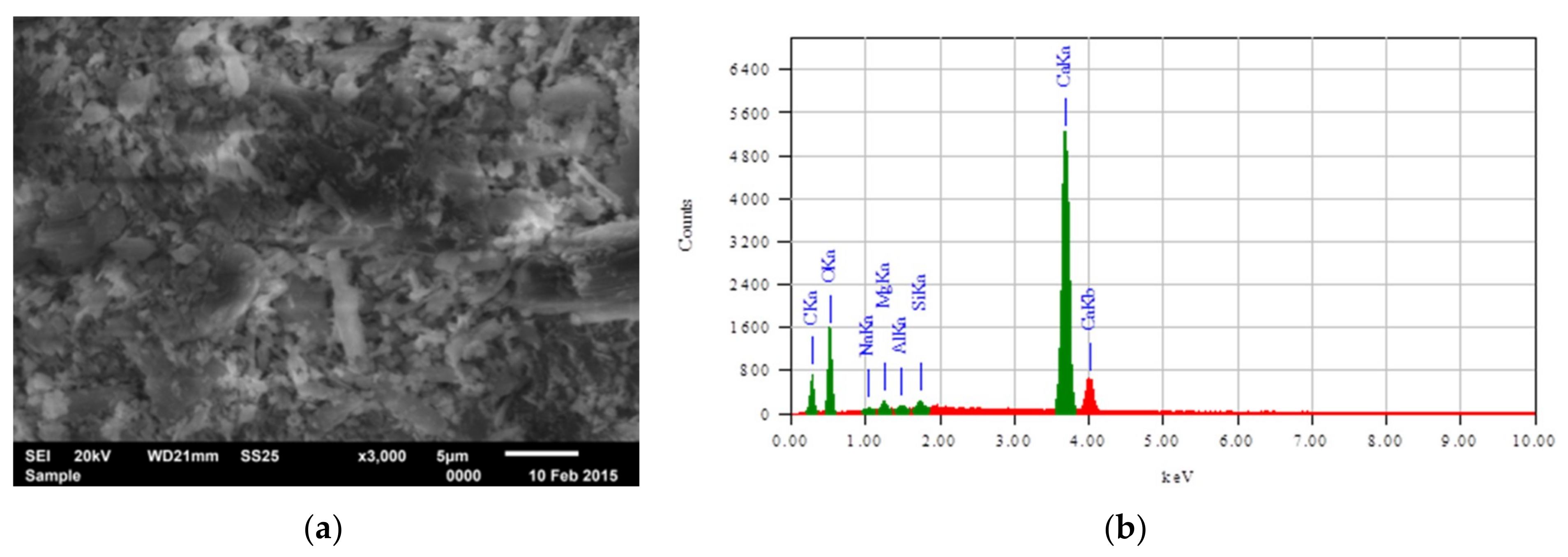
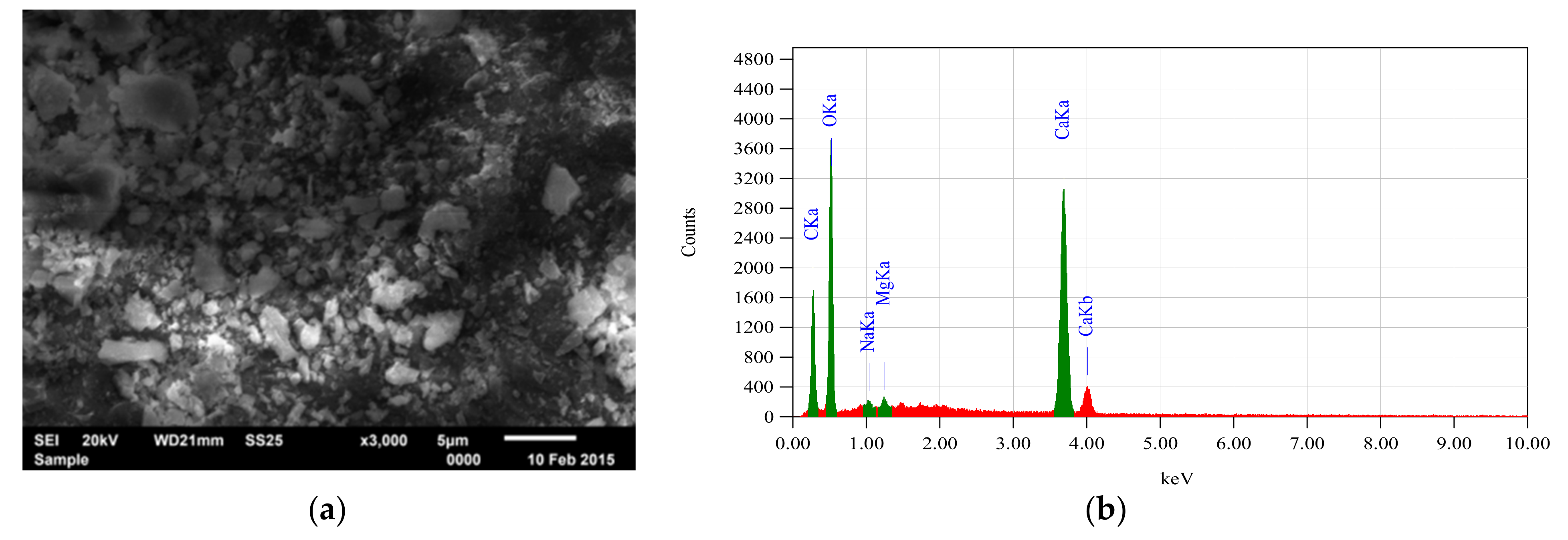
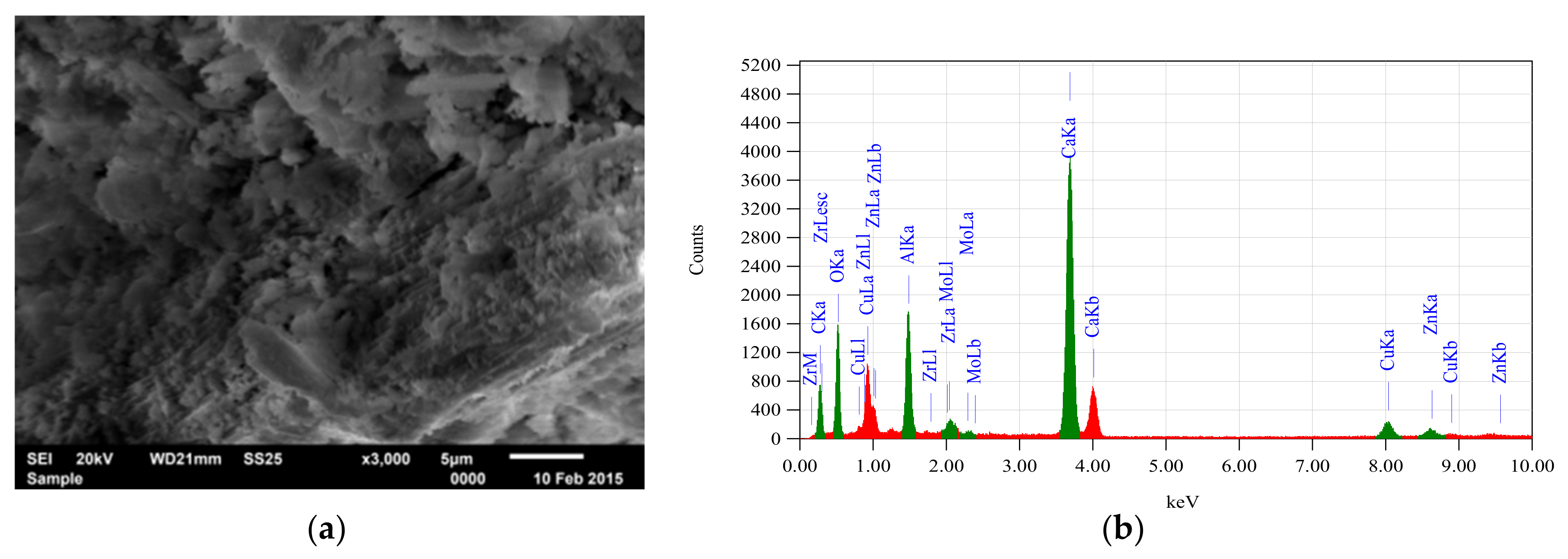
27]. The porosity properties of the material were observed using a Scanning Electron Microscope (SEM) to analyze the differences of the surface morphology of the three shell species. The content of carbon in the shells flour was also observed in relation to the acoustical performances of either sound absorption or transmission loss (STL).
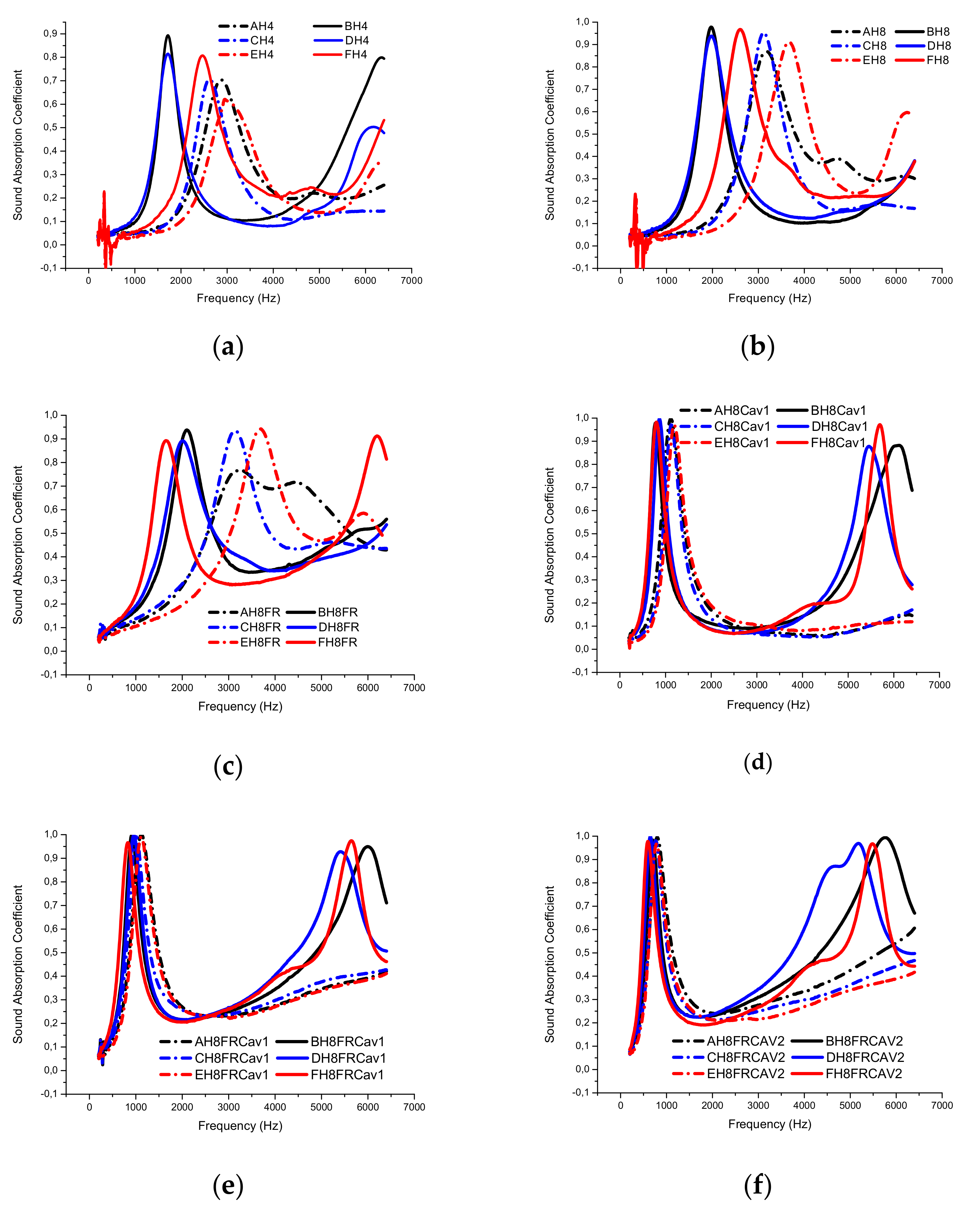
A transfer function using the impedance tube technique with two microphones referring to ASTM E-1050 was conducted to measure the sound absorption coefficient. Each sample was treated in three different ways as listed in Table 1. The B & K 4206 impedance tube with a small tube dimension used in this experiment had a sound frequency range up to 6.4 kHz. The effect of the addition of resonators towards sound absorption on the 30 mm diameter material sample was investigated in an acoustic laboratory. The method of treatment was to drill the sample to form a quarter wave length resonator structure. The resonator diameter was 3 mm, while the number of resonators was either 4 or 8 as listed in Table 1. The additions of a 10 mm back cavity and porous front layer were applied to the SFRP sample to determine their effects on sound absorption. The front porous layer was made of commercial dacron lining.
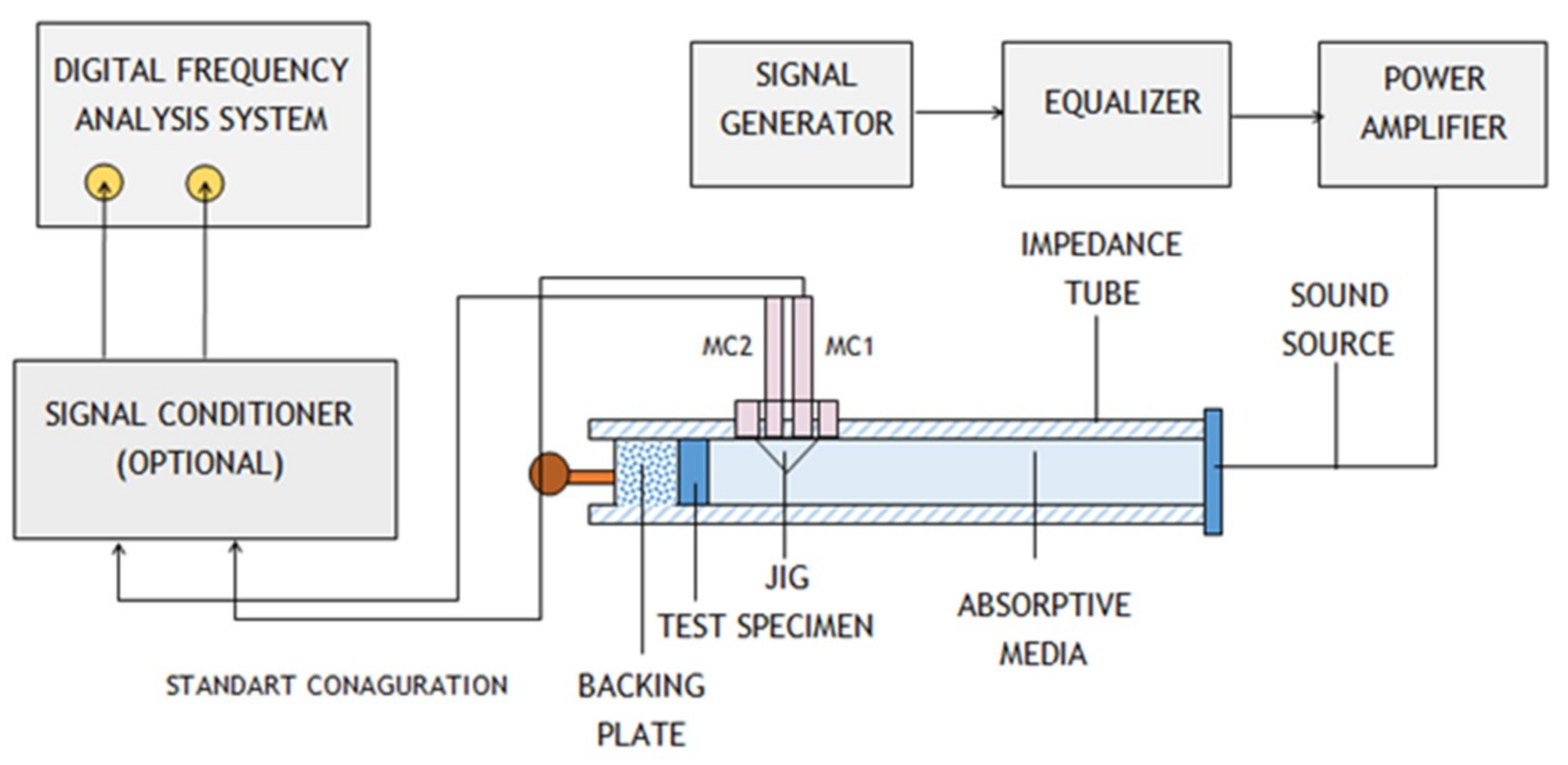
The impedance tube B & K 4206 was connected to four LAN-XI B & K Analyzer channels and was fully controlled by the computer. All experiments were controlled by B & K material testing software. In the experiment, the impedance tube power amplifier disseminates the random noise as the sound source along the tube before touching the surface of the test specimen (see Figure 1). Two ¼-inch 4187 B & K microphones capture both incident and reflected waves before they are decayed by using transfer function analysis. The decomposed sound energy and the process of decay must be entirely associated with the absorption performance of the sample.
The frequency response function H12 and reflection coefficient R can be expressed as follows,
H 1 , 2 = P 2 P 1 = e j k h + e j k h e j k ( h + s ) + e j k ( h + s )
and
R = H 1 , 2 e j k s e j k s H 1 , 2 e j 2 k ( h + s )
with P1 and P2 being the sound pressure levels captured by the two microphones in position one and two respectively; k is the wave number while h and s represent the distance from the first microphone to the sample and the respective distance between microphones. The coefficient of absorption α can be calculated by:
α = 1 [ R ] 2
Several theories have been developed to determine the STL of a material. One research was conducted by Tenenbaum, R., A. and Magalha, M.B.S., who observed the character of compound walls related to the STL This study performed theoretical and analytical studies on how to quickly calculate the loss of transmission in compound wall construction. Compound walls with multiple layers of absorber had more effective acoustic performance than single walls of the same thickness. The theoretical model used provided an easy way to evaluate transmission loss and guided the procedure to determine the optimal material choices to be used in the partition [
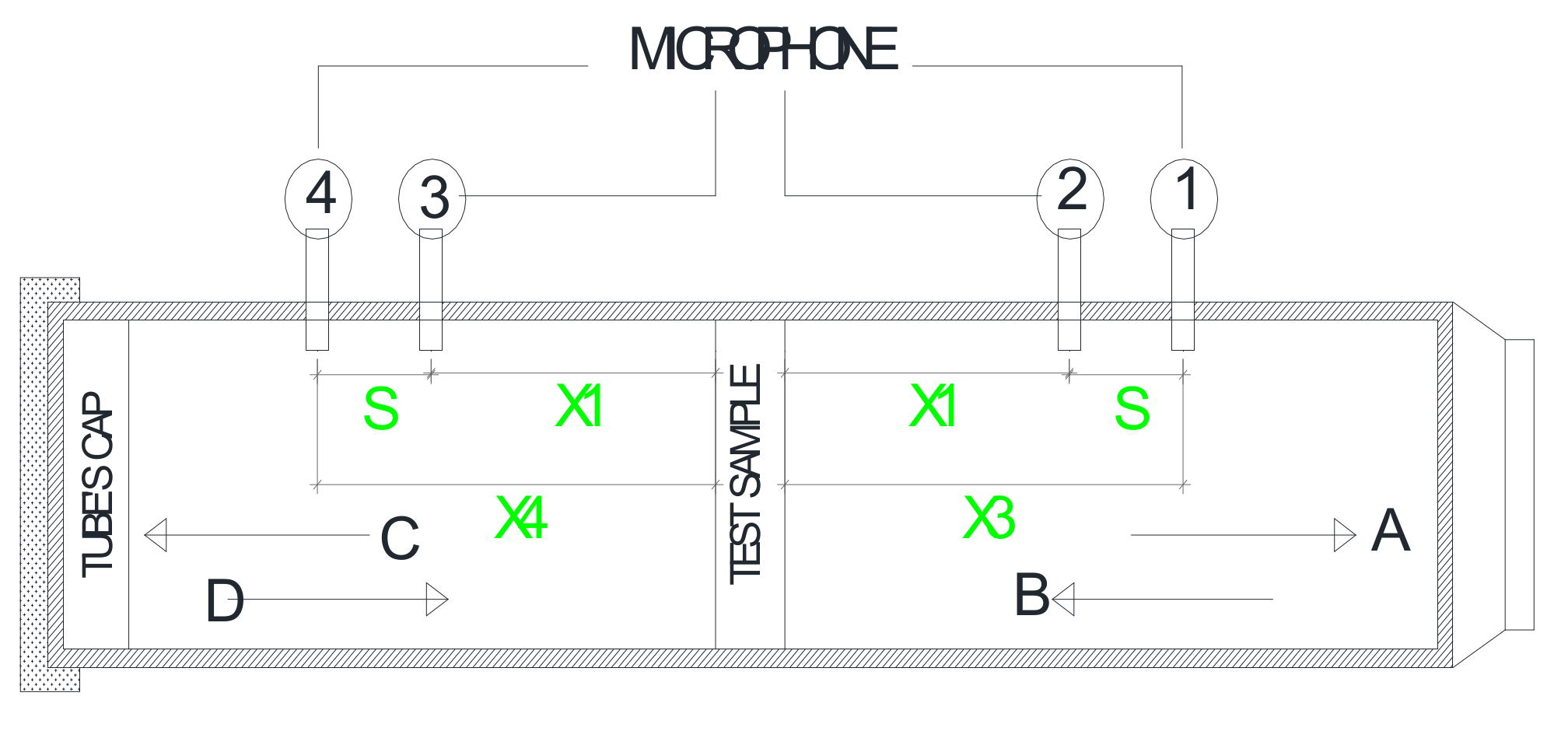
29]. The distance between two microphones is assumed to be the same to simplify the STL equation, so the sound transmission loss can be calculated by Equation (5) below,
S T L = 20 log | e j k s H 1 , 2 e j k s H 3 , 4 | 20 log | S d / S u |
where S = | x 1 x 2 | = | x 3 x 4 | ; H 1 , 2 = P 2 / P 1 is the transfer function of sound pressure at position 1 and 2; H 3 , 4 = P 4 / P 3 is the transfer function of sound pressure at position 3 and 4; S d / S u is the ratio between the auto spectrum in both the upstream tube and the downstream tube.
Figure 2 illustrates the schematic diagram of sound transmission loss measurement. Four microphones of B & K 4187 were located in the upper and lower tubes used in this investigation. The white noise was driven by a spectrum analyzer of B & K 3160-A-042 and amplified with a power amplifier of B & K 2716C generated by a hard speaker mounted on the upper tube. The sound captured in the microphone was then processed in the module of B & K 3160-A-042. In this experiment, a lower tube type was used to achieve a high frequency test for soundproofing. Specimens with thicknesses of 15 mm and 30 mm were used for the anechoic termination in the lower tube.

3. Results and Discussions

3.1. Sound Absorption Coefficient

The samples of SFRP were tested and analyzed in the acoustical laboratory using the impedance tube with microphones. To make sure that there would be differences on the results because of treatments, the samples were first measured on their original acoustics without treatment. Then, after measuring the origin performances, the treatments of resonators, additional fibrous layer, and cavity were applied respectively. Below Figure 3 illustrates that composite shells having 30 mm thickness have a better absorption coefficient performance compared to the ones having 15 mm thickness. In the 30 mm ones, Placuna placenta shell has a wider broadband frequency than the other two shells. Associated with density material, this result is in accordance with other research conducted by Nandawar et al., [25] where decreasing density on fiber boards improves sound absorption ability (see Figure 3). Placuna placenta with 30 mm thick and density 1.392 gram/cm3 had the best sound absorption followed by Anadara granosa with density 1.643 gram/ cm3. Creating four resonator holes gives the quarter wavelength the ability to increase the value of absorption coefficient at high frequency, especially in composite shell made of Anadara granosa and Perna viridis shell flour (see Figure 3).
Figure 4a presents the samples with additional holes as resonators indicated by H4. The presence of four resonator holes changed the absorption performance that was initially below 0.1 to be above 0.1 (see Figure 4a). Figure 5b illustrates that the addition of eight resonator holes (H8) can increase the absorption value to almost 1.0 in all species of composite shell species. In this treatment, the absorption of the 15 mm value composite shell also increased up to 0.9 in the frequency range of 3.0–3.7 kHz. This phenomenon is caused by viscous damping that occurred in the resonator holes when sound energy passed through the material structure (see Figure 4a,b).
The addition of fibrous layers in the material structure was able to shift the acoustical performance of composite shell made of Placuna placenta flour to low frequency. On the other hand, the composite shell made from Anadara granosa and Perna viridis flour shifted to a higher frequency than before. This is possible because the surface morphology of Placuna placenta is softer while Anadara granosa and Perna viridis have a rougher surface morphology. The addition of fibrous layers not only shifted the absorption performance to a lower frequency than before, but it also caused the absorption value to rise, mostly above 0.2 at 1000 Hz frequency (see Figure 4c). In contrast to 30 mm composite shells, the Placuna placenta Linn materials having a thickness of 15 mm shell composites has better absorption performance at higher frequencies compared to composite shells made of Anadara granosa and Perna viridis flour. This is due to the absorption behavior of thin materials that have good performance at a higher frequency compared to thick materials.
The addition of a 10 mm cavity produced a different sound wave behavior phenomenon with the addition of fibrous layers to the material structure. In addition to the 10 mm cavity, the absorption performance shifted to a lower frequency of about 1000 Hz with a narrower frequency range of sound waves than with the addition of fibrous layers (see Figure 4d). This result agrees with the finding on research conducted by Chen, Liang, and Yi, 2016 [31] as well as Lee and Chen, 2001 [5]. Meanwhile the addition of coupled fibrous layers and cavity can increase the absorption coefficient value mostly above 0.2 at low frequency and high frequency at about 1.0 kHz and 4.0–5.0 kHz respectively. This finding agrees with the study conducted by Kristiani et al., and Romadhona et al., [32,33]. Figure 4d,e shows quite significant differences. In the coupled structure consisting of 8-hole resonators and 10 mm cavity (H8Cav1), there is a difference in the low frequency zone between 30 mm and 15 mm composite shells. However, the addition of a fibrous layer to the coupled structure was able to shift the absorption performance of the 15 mm materials to the lower frequency so it coincided with the absorption performance of 30 mm materials (see Figure 4e). Besides, this triple structure was also able to raise all absorption coefficient values above 0.2 with a starting frequency of 550 Hz. In conclusion, this material structure can be categorized as a good absorber. Figure 4f describes that the expansion of the cavity to 20 mm permits the composite shell made of large pores to effectively absorb sound. Comparing to the studies conducted by Li and Crocker (2005) and Arenas (2003), this result seems to be in agreement [34,35].

3.2. Surface Design Treatment of Placuna placenta SFRP on Absorption Performances

Several studies on surface design treatment in samples to improve acoustic performance have been carried out by a number of researchers [36,37,38,39,40]. Tang et al studied on a hybrid-perforated honeycomb patterned sandwich panel which effectively absorbs sound in low frequencies. Numerical simulation was used to establish the theoretical model of sound absorption and bending stiffness [38]. Furthermore, since the MPP structure is not effective for low frequencies, Xiao-dan et al. proposed a parallel mechanical impedance structure arranged in the cavity of MPP to improve its absorption capabilities in low frequencies. Using transfer matrix method and standing wave tube, they found that the new structure had three important peaks at 0.85, 0.40, and 0.60 ranging from 200–600 Hz [41]. The surface design treatment carried out by the researchers includes form folds on origami pattern, making cavities in the form of perforated as well as micro perforated panels, and design of honeycomb patterns. However, surface design research using a combination of cavity and slit to form tadpoles has never been done elsewhere. Based on the comparative absorption performances of materials in previous subheadings, we know that the Placuna placenta SFRP has the best acoustical behavior compared to the others. The next discussion is in confronting the two surface design treatments of the shell SFRP. The first design treatment is the Side-Tailed Cavity Treatment (STCT), while the second is the Front-Tailed Cavity Treatment (FTCT). The surface treatment method was done by slicing the sample in the middle of the field then drilling the hemisphere so that it formed a configuration like the tail of a tadpole (see Figure 5).
Figure 5 illustrates the samples with tailed cavity inclusion in the Placuna placenta FRP. Cavity surface design was applied on the samples with Side-Tailed Cavity Treatment (STCT) and Front-Tailed Cavity Treatment (FTCT). The cavity has 4 mm diameter and the slits have 2 mm width. Comparative methods were implemented by using standing wave methods referring to ASTM E 1050-98 with B&K impedance tube. First, the side-tailed cavity samples with 15 mm and 30 mm thickness were measured, then in the second tests, the front-tailed cavity samples with 15 mm and 30 mm were observed respectively. The results can be explained as seen in Figure 6 for STCT and Figure 7 for FTCT.
Many studies discussed perforated and micro perforated panels [40,42,43,44,45]. For example, inhomogeneous perforated with various cavity depth panels was performed by Mosa et al. Dividing into two sub areas, the sample has various hole diameters, perforation ratio and is supported with back cavity. Using the impedance model and normal incidence sound wave, it was found that the model can be considered as an effective absorber at low frequencies bandwith [40]. Meanwhile, other research conducted by Min and Guo observed and proposed MPP absorbers with various depth sub-cavities based on quadratic residue sequences. Using predictive analyses on the normal sound incidence, they successfully found out that the MPP has good performances at wideband frequencies starting from 0.4–3.5 kHz with the peak of 0.98 [42]. A different study was conducted by Echeverria et al., who observed and proposed natural-synthetic fiber waste recycled into Hybrid Fibrous Reinforce Composite (HFRC) for sound absorber in building application. Since the World Health Organization considered urban noise as a major source of environmental pollution disturbing global industrialized urban housings, this research focus on the sound absorption performances of the HFRC. Although having low absorption in the middle frequencies (0.4–2.5 kHz) and higher absorption in higher frequencies, 2.5–6.4 kHz, this material indicated an absorption peak of 0.78 in the prototype with less filler matrix. The HFRC with less filler matrix could be used for building elements, especially for urban settlements which are disturbed by urban noise hazards [44].
Figure 6 illustrates the different performance of 15 mm and 30 mm Placuna placenta composite with Side-Tailed Cavity Treatment (STCT). The results show that the 15 mm Placuna placenta composite with STCT has its peak at 0.42 at 0.9 kHz, while the 30 mm one has its peak at 0.81 at 1.9 kHz. Comparing to the research by Tang et al., that a thinner honeycomb patterned panel has more effective absorption capabilities than the others, this result tends to agree with the study conducted by Tang et al [38]. The cavity location inside the sample causes the sound energy to be saved longer than for any samples of cavity in the material surface. The hidden channel and hole make an effective absorption due to the viscous damping effect.
Figure 7 illustrates the difference in the absorption capacity of 15 mm and 30 mm Placuna placenta composite with Front-Tailed cavity Treatment. Figure 7a shows that the cavity behind the sample as deep as 10 mm and 20 mm is able to shift maximum material absorption capability to low frequencies as much as 0.75 and 0.66 respectively ranging at 500–1000 Hz, although with a sound absorption peak lower than the sample without back cavity. Unlike the sample with 15 mm thickness, the 30 mm Placuna placenta composite with Front-tailed Cavity Treatment had higher peaks at low frequencies when 10 mm and 20 mm back cavities depth were added. Figure 7b illustrates that the additional air gap 10 mm and 20 mm in Placuna placenta composite with front-tailed cavity treatment can shift the sound absorption to the peaks 0.91 and 0.90 respectively at low frequencies 500–1 kHz. Comparing to the Placuna placenta composite, the 30 mm one tends to have lower ability on sound absorption, because the 15 mm Placuna placentacomposite without air gap reaches wideband frequencies starting from 2 kHzs. This result agrees with the theories and findings in studies conducted by Mosa et al., Gai et al., and Wang et al. [36,40,46].
Figure 8 illustrates a comparative graph confronting the Side-Tailed Cavity (STCT) and Front-Tailed Cavity (FTCT) on either 15 mm or 30 mm Placuna placenta composite without additional back cavities. As mentioned in the previous discussion, the 15 mm and 30 mm Placuna composites reached peaks of sound absorption below 2000 Hz at 0.42 and 0.81 respectively. Continuing on the discussion about the front-tailed cavity treatment, Figure 8 illustrates a significant difference when the 15 mm and 30 mm Placuna composite with FTCT reaches the peak 0.85 and 0.64 respectively at frequencies 2.5–3.0 kHz. Comparing other studies conducted by Tang et al., Xiao-dan et al., Gai et al., and Carbajo et al., this finding agrees with their theories regarding the thin acoustic panel on sound absorption performances [36,38,41,43].

3.3. Sound Transmission Loss (STL)

Sound Transmission Loss (STL) material looks stable at 55–58 dB in the SFRP material structure without treatment (see Figure 9a). In the treatment of 8-hole resonators, the ability of transmission loss material appears to decrease at 51–55 dB. This phenomenon occurs because there is a half wavelength phenomenon that transmitted the sound to the opposite surface (see Figure 9b). Additional fibrous layer to the sample does not have a significant effect in changing the transmission loss performance, because sound energy is transmitted by resonators and the porous surface on the fibrous layer does not negate the sound that touches the material surface (see Figure 9c).
Figure 9a–c illustrate the sound transmission loss capabilities of the material. In the samples without treatment, the STL of the materials stayed between 55–58 dB. As the half wavelength phenomenon occurred, in the samples treated with eight holes of resonator, the STL was slightly decreased at 51–55 dB. In the combined treatment of resonators and fibrous layers, the ability of the transmission of loss material slightly increased to 52–56 dB which is still below the ability of the material without treatment. Because the half wavelength penetrates the material to the opposite surface, it is then blocked by the fibrous layers, even though the layers still transmit some of the sound waves in a continuous direction with lesser amounts (see Figure 9c). The difference in material thickness has a significant effect on the phenomenon of the shell composite on sound transmission loss. The shell composite with a thickness of 15 mm has a better transmission loss performance compared to the one having a thickness of 30 mm. This is because the rapid transmission process disappears on the thinner panels rather than on the thick panels. The thick panels will store sound energy longer than the thin panels. This is in accordance with the logic given in studies on the effect of density on sound transmission loss by Narang and Ko, et al., where in both studies, density causes a fluctuating effect on sound transmission loss performance [26,27].

3.4. Simple Surface Morphology

Surface morphology in this study relies on the results of the magnification of the Scanning Electron Microscope of the three shellfish flours. EDX oxide results are needed in analyzing the percentage of shellfish constituents associated with acoustic performance both sound absorption coefficient and sound transmission loss (STL) fiber reinforced polyester shell (SFRP). It can be seen from the SEM analysis that the image of each shell consists of stem shapes with varying morphological sizes. This can happen because of grinding and clumping occurring during the grinding process, therefore the distributions of the morphological size of each shell were varied. The morphological analyses on the Anadara granosa Linn and Placuna placenta Linn appear to have smaller pores than Perna viridis Linn (see Figure 10, Figure 11 and Figure 12); the Perna viridis Linn pores are clearly visible (see the Figure 11a,b). Placuna placenta Linn and Anadara granosa Linn have the possibility to absorb more sound compared to the Perna viridis Linn. The materials with smaller and solid pores have greater absorption power than the materials with large pores. These findings seem to agree with the results of studies conducted by Dan, et al., Raju, et al., Zander, et al., and Bechwati, et al. [47,48,49,50].
When viewed from the Sound Absorption Coefficient, composites with 30 mm thickness without treatment have an absorption coefficient of around 0.45 with the highest absorption frequency in the range of 1500 Hz for Anadara granosa Linn and Perna viridis Linn and of 2100 Hz for Placuna placenta Linn. Furthermore, the seashell with a thickness of 15 mm has an absorption coefficient around 0.25, 0.29, and 0.35 for Placuna placenta Linn, Perna viridis Linn, and Anadara granosa Linn respectively. The treated seashell that was perforated creating four holes at 30 mm thickness has an absorption coefficient of 0.83, the highest absorption frequencies at 1700 Hz and 2500 Hz respectively for composite with Perna viridis Linn and Placuna placenta Linn fillers, and an absorption coefficient of 0.9 with the highest frequency absorption of 1700 Hz for the Anadara granosa Linn. At a thickness of 15 mm, the absorption coefficients are around 0.7 for Perna viridis Linn and Anadara granosa Linn, and 0.62 for Placuna placenta Linn.
In the 8-hole treatment at the thickness of 30 mm, the seashell composites are ranked as follow: Placuna placenta Linn has an 0.97 absorption coefficient with the highest absorption frequency at 2600 Hz, Anadara granosa Linn has the highest absorption frequency at 2000 Hz, and a 0.92 absorption coefficient for Perna viridis Linn with the highest absorption frequency at 2000 Hz. On the other hand, at 15 mm thickness, the absorption coefficient for each composite is 0.84 (Placuna placenta Linn filler), 0.92 (Perna viridis Linn), and 0.90 (Anadara granosa Linn). Sound absorption loss analysis for each composite with a thickness of 30 mm shows the STL value of 54.5 dB; 54.0 dB; 53.5 dB for Placuna placenta Linn, Perna viridis Linn, and Anadara granosa Linn respectively. On the other hand, the composites with 15 mm thickness respectively have STL values of 58 dB, 57.5dB, and 56 dB for Placuna placenta Linn, Perna viridis Linn, and Anadara granosa Linn fillers. Where sound absorption starts to stabilize from the frequency range of 500 Hz, it appears that composites with Placuna placenta Linn filler are the most stable compared to the other shell fillers. From the sound absorption coefficient analysis, the treatment on the test composite by adding resonator holes also increases the value of the sound absorption coefficient. The composites with eight holes of resonator treatment have the highest sound absorption coefficient value. The composite with Placuna placenta Linn filler, with 8-hole treatment and 30 mm thickness, has the highest coefficient value (0.97) which is not much different from the Placuna placenta Linn filler that has a thickness of 15 mm (0.9). This is comparable to the SEM analysis showing that Placuna placenta Linn has relatively small, regular, and solid pores compared to the other two types of shells and the smaller, more regular, and more solid the pores, the higher the sound absorption volume will be (see Figure 10, Figure 11 and Figure 12). On the other hand, the sound transmission loss analysis shows that composites with the Placuna placenta Linn filler have the highest transmission loss value compared with other types of shells. Composites with Placuna placenta Linn filler with 30 mm thickness have an STL value of 54.5 dB and 58 dB for the ones with 15 mm thickness. It shows that composites with a thickness of 15 mm have a good ability in eliminating sound. From this analysis, it can be seen that Placuna placenta Linn has the best sound absorption ability compared to other shell composites.

3.5. Oxide Analysis of Seashells

The EDX oxide analysis shows the percentage of the elements contained in seashell flour. In a number of studies, the performance of a material is influenced by its oxide content [47,48,49,50]. In a previous study, for example, Long, et al. concluded that the carbon mass ratio influenced the increment of acoustic velocity and the composite impedance [47]. While referring to other studies, the acoustic performance could be influenced by the content of calcium oxide [48], the nano-tube array [49], and the activated carbon at low frequencies [50]. The composition of each shell from the EDX oxide analysis can be seen in Table 3, Table 4 and Table 5 above. The Placuna placenta is identified as having a dominant carbon content of 93.56% mass (see Table 5), while Perna viridis Linn has a dominant carbon content of 55.36% mass and calcium oxide of 42.04% mass (see Table 4), furthermore, Anadara granosa has a dominant calcium oxide of 67.16 % mass and carbon of 27.39% mass (see Table 3).
The carbon content as tested in the shells has the ability to absorb sound over a certain range. The presence of carbon, in addition to the presence of pores, in the shells also adds to the absorption of sound. The Placuna placenta has the highest carbon mass compared to other tested shells; it was indicated that the absorption ability of Placuna placenta is the best compared to other seashells [3,4]. This is reinforced by the sound absorption coefficient analysis which shows that the Placuna placenta has the best sound absorption compared to the other tested shells. From the EDX oxide analysis, it can be seen that Anadara granosa Linn has the highest calcium mass content, in the form of calcium oxide (see Table 3), compared to the others. The content of calcium oxide and the hardness of the material makes the insulation power of this shell type quite good. As seen in the sound transmission loss test, composite made of Anadara granosa has the highest value compared to others. The results seem to agree with the studies conducted by Dan, et al., Raju, et al., Zander, et al., Bechwati, et al., Cybulska, et al., and Jalili, et al. [47,48,49,50,51,52]. Applications on buildings often use the concept of a double skin facade. A research of absorber panels in the form of perforated panels was discussed by K. Sakagami and M. Morimoto (2008) [53]. Similar to the study of Sakagami and Morimoto, this panel damper was applied to the interior and supported by air cavities. However, in the field this panel was then reinforced with an aluminum frame in order to stand upright [53]. The advantage of a double skin facade construction is the benefit of the building for thermal, as well as noise disturbances. The present study introduces a sample application on buildings by using a diffuser absorber from a shell filler-reinforced with unsaturated polyester in waffle patterns for the building interior (see the Figure 13a–c).
Applications on the interior of the building could be conducted by installing a diffuser–absorber as illustrated in Figure 14a–c. The use of diffuser–absorber in Figure 15 is briefly similar to that in the study of Echeverria et al., Carbajo et al., Dupont et al., and Romadhona et al [33,43,44,54]. In their research, the observed materials had sound absorbing ability at low frequencies. The side-tailed cavity treated diffuser made of Placuna fiber reinforced polymer could be used as an interior acoustical material in buildings. Furthermore, the application of front-tailed cavity treated Placuna composite is shown in Figure 14c as a diffuser–absorber which has the ability to absorb sound in the middle to high frequencies starting from 2.0 kHz to 6.4 kHz. As in the previous discussion, these types of diffusers are very good to absorb sound energy at 3.0 kHz and 6.0 kHz.
Figure 15 illustrates the diffuser–absorber mounted on the wall of the building using an aluminum frame and screwed. Uneven surfaces have a role in absorbing and diffusing sound energy. Comparing to other researches such as Mosa et al., Carbajo et. Al., Echeverria et al. and Sarvestani et al. [40,43,44,55], the middle to high frequencies ability on the sound absorption occurred due to the cavities and viscous damping effects. These findings are suitable for acoustical materials for the buildings interior.

4. Conclusions

This research produced some conclusions relating to the acoustical performance and the treatment effects on sound insulation improvement in the material structure of seashell composites. Related to sound absorption improvement, it was found that the addition of resonators and fibrous layers in the material structure effectively improves the acoustical performance at low frequencies; even though in a narrow frequency range. In an improvement effort, the additions of resonator combinations, fibrous layers, and cavities gave a positive effect in increasing sound absorption at high frequencies with a wide frequency range. Moreover, the combination of all three also affects the increase in sound absorption value; mostly above 0.2 at a frequency above 2.0 kHz.
In combination with the addition of a material structure with resonators, fibrous layers, and cavities, it was found that the 30 mm composite shell had better acoustical performance at high frequencies compared to the 15 mm composite shell. On the observation of the sound transmission loss, the addition of resonator holes decreased the transmission performance of the material structure because the occurring half wavelength propagation process is quickly transmitted to the opposite surface. The shell composite with a thickness of 15 mm has a better transmission loss performance compared to the shell composite having a 30 mm thickness because the rapid transmission process disappears on thinner panels rather than on thick panels. The thick panels will store sound energy longer than the thin panels. Continuing, the Placuna placenta Linn filler composite with an 8-hole treatment and 30 mm thickness has the highest coefficient value, as much as 0.97, which is not much different from the Placuna placenta Linn filler that is 15 mm thick. This is comparable to the SEM analysis showing that Placuna placenta Linn has relatively small, regular, and solid pores compared to the other two shell types. Furthermore, composites with Placuna placenta Linn filler 30 mm thick have an STL value of 54.5 dB and 58.0dB for the composites with a thickness of 15 mm. This shows that composites with 15 mm thickness have good ability in eliminating sound.
In the end results, the Placunas composites were treated by the side-tailed cavity and front-tailed cavity where these composites have a quite good performance at middle to high frequencies and reach wideband frequencies and peaks of 0.85 on sound absorption coefficient especially for the 15 mm Placuna composite with front-tailed cavity. This research enriches the discourse about materials made of seashell waste which can be recycled into acoustical building materials. Although naturally tough, the acoustical performance of these materials was successfully improved with the front tailed cavity treatments. By using ATSM methods, these materials were proved of their acustical behavior and could be considered as diffuser–absorber in buildings. Finally, the side-tailed cavity and front cavity treated placuna composites have qualified performances on sound absorption and might be used as diffuser–absorbers in interior buildings application. Due to the tight times on manufacturing the materials for scale-up, it is suggested to measure and observe the materials in the an-echoic chamber to ensure the reverberation time performance in further research. Regarding the development of the material for implementation in buildings, research on the material quality improvement should be conducted in collaboration with the related manufacture as the third party.

Author Contributions

Conceptuatization, E.S.; Introduction and Methodology, G.H. and E.S.; Visualization map and graphs, P.; Analyzing Data and Interpretation, E.S. and M.A.B.; Documentation and photography, G.H.; Conclusion, E.S. and M.A.B.

Funding

This research was granted by Ministry of Research, Technology and Higher education with research grant number 149-06/UN7.5.1/PG/2015 on MP3EI fiscal year 2015, grant number 101-73/UN7.P4.3/PP/2018 on Competence Based Research (PBK) and the Diponegoro University—grant number 474-106/UN7.P4.3/PP/2018 on RPI fiscal year 2018.

Acknowledgments

Authors give thanks to the Ministry of Research, Technology and Higher Education and the Research Centre of the Diponegoro University for the opportunity in conducting studies in acoustical material for buildings.

Conflicts of Interest

We declare that the grantors did not have any intervention in any part of this research.

Nomenclatures

SFRPSeashell Fiber Reinforced Polymer
ASTMAmerican Standard Testing and Material
FRPFiber Reinforced Polymer
αSound absorption coefficient
STLSound Transmission Loss
MPPMicro Perforated Panel
QRDQuadratic Residue Diffuser, the type of acoustical components in buildingss
B & KBruer & Kjaer, manufacture name of the Impedance Tube to measure and observe the acoustical behavior of material
STCTSide-Tailed Cavity Treatment of samples
FTCTFront-Tailed Cavity Treatment of samples
HFRCHybrid Fibrous Reinforce Composite
HNumber of quarter wavelength resonators (4,8)
FRFoam Front Layer
CavCavity (10 mm)
EDXEnergy Dispersive Spectroscopy (EDS) oxide
ZAFMatrix effect in EDS oxide, related to all elements presents in the sample and in the standard covering Production (Z), Absorption (A) and enhancement of the characteristic radiation (F) that must be taken into account.

References

  1. Tronchin, L.; Manfren, M.; Nastasi, B. Energy efficiency, demand side management and energy storage technologies—A critical analysis of possible paths of integration in the built environment. Renew. Sustain. Energy Rev. 2018, 95, 341–353. [Google Scholar] [CrossRef]
  2. Ellen MacArthur—Foundation, Circularity in the Built Environment: Case Studies a Compilation of Case Studies from the CE100; Ellen MacArthur Foundation: London, UK, 2016.
  3. Setyowati, E.; Hardiman, G.; Khusnan, P. Green concrete made of oyster shell waste to support green building material. J. Teknol. 2016, 78, 203–207. [Google Scholar]
  4. Setyowati, E.; Hardiman, G. The Acoustical Performances of Oyster Shell Waste Based Green Concrete Materials. GSTF J. Eng. Technol. 2015, 3, 1–6. [Google Scholar]
  5. Lee, F.C.; Chen, W. Acoustic Transmission Analysis of Multi-Layer Absorbers. J. Sound Vib. 2001, 248, 621–634. [Google Scholar] [CrossRef]
  6. Bravo, T.; Maury, C.; Pinhède, C. Absorption and transmission of boundary layer noise through flexible multi-layer micro-perforated structures. J. Sound Vib. 2017, 395, 201–223. [Google Scholar] [CrossRef]
  7. Takahashi, Y.; Otsuru, T.; Tomiku, R. In situ measurements of surface impedance and absorption coefficients of porous materials using two microphones and ambient noise. Appl. Acoust. 2005, 66, 845–865. [Google Scholar] [CrossRef]
  8. Odusanya, A.A.; Bolasodun, B.; Madueke, C.I. Property Evaluation of Sea shell Filler Reinforced Unsaturated Polyester Composite. Int. J. Sci. Eng. Res. 2014, 5, 1343–1349. [Google Scholar]
  9. Fombuena, V.; Bernardi, L.; Fenollar, O.; Boronat, T.; Balart, R. Characterization of green composites from biobased epoxy matrices and bio-fillers derived from seashell wastes. J. Mater. 2014, 57, 168–174. [Google Scholar] [CrossRef] [Green Version]
  10. Teixeira, L.B.; Fernandes, V.K.; Maia, B.G.O.; Arcaro, S.; de Oliveira, A.P.N. Vitrocrystalline foams produced from glass and oyster shell wastes. Ceram. Int. 2017, 43, 6730–6737. [Google Scholar] [CrossRef]
  11. Li, L.; Zeng, Z.; Wang, Z.; Peng, Z.; She, X.; Li, S. Effect of Oyster Shell Powder Loading on the Mechanical and Thermal Properties of Natural Rubber/Oyster Shell Composites. Polym. Polym. Compos. 2017, 25, 17–22. [Google Scholar] [CrossRef]
  12. Setyowati, E.; Budihardjo, M.A.; Putri, A.R. Establishing Grounds for Building Orientation Mapping and Validation of Noise Level Correlation modelling on Aircraft Take-off and Landing. Buildings 2019, 9, 27. [Google Scholar] [CrossRef]
  13. Setyowati, E.; Pandelaki, E.E. The concept of sustainable prefab modular housing made of natural fiber reinforced polymer The concept of sustainable prefab modular housing made of natural fiber reinforced polymer (NFRP). IOP Conf. Ser. Mater. Sci. Eng. 2018, 316, 1–9. [Google Scholar] [CrossRef]
  14. Setyowati, E.; Hardiman, G.; Pandelaki, E.E. Structural, acoustic, and aesthetic performances of double layer wall made of oyster shell and polymer as green material in green construction. AIP Conf. Proc. 2018, 1977, 040033. [Google Scholar]
  15. Yahya, I.; Kusuma, J.I.; Kristiani, R.; Harjana, R.K.; Hanina, R. Laboratory investigation on the role of tubular shaped micro resonators phononic crystal insertion on the absorption coefficient of profiled sound absorber. IOP Conf. Ser. Mater. Sci. Eng. 2016, 107, 012046. [Google Scholar] [CrossRef] [Green Version]
  16. Yahya, I.; Harjana. New Sound Absorption Improvement Strategy for Qrd Element. In Proceedings of the 20th International Congress on Sound and Vibration (ICSV20), Bangkok, Thailand, 7–11 July 2013; pp. 1–9. [Google Scholar]
  17. Vigran, T.E. Normal incidence sound transmission loss in impedance tube—Measurement and prediction methods using perforated plates. Appl. Acoust. 2012, 73, 454–459. [Google Scholar] [CrossRef]
  18. Meng, H.; Galland, M.A.; Ichchou, M.; Bareille, O.; Xin, F.X.; Lu, T.J. Small perforations in corrugated sandwich panel significantly enhance low frequency sound absorption and transmission loss. Compos. Struct. 2017, 182, 1–11. [Google Scholar] [CrossRef]
  19. Kar, T.; Sharma, P.P.R.; Munjal, M.L. Analysis of multiple-duct variable area perforated tube resonators. Int. J. Acoust. Vib. 2006, 11, 19–26. [Google Scholar] [CrossRef]
  20. Ayub, M.; Fouladi, M.H.; Ghassem, M.; Nor, M.J.M.; Najafabadi, H.S.; Amin, N.; Zulkifli, R. Analysis on multiple perforated plate sound absorber made of coir fiber. Int. J. Acoust. Vib. 2014, 19, 203–211. [Google Scholar] [CrossRef]
  21. Kidner, M.R.F.; Hansen, C.H. A compARison and review of theories of the acoustics of porous materials. Int. J. Acoust. Vib. 2008, 13, 112–119. [Google Scholar]
  22. Hua, Q.I.U.; Enhui, Y. Effect of Thickness, Density and cavity Depth on the Sound Absorption Properties of Woll Boards. AUTEX Res. J. 2017, 1–6. [Google Scholar]
  23. Wang, C.; Torng, J. Experimental study of the absorption characteristics of some porous fibrous materials. Appl. Acoust. 2001, 62, 447–459. [Google Scholar] [CrossRef]
  24. Latif, N.A.; Rus, A.Z.M.; Zaimy, M.K.A.G. Effect of Thickness for Sound Absorption of High Density Biopolymer Foams. Key Eng. Mater. 2014, 595, 183–187. [Google Scholar] [CrossRef]
  25. Nandanwar, A.; Kiran, M.C.; Varadarajulu, K.C. Influence of Density on Sound Absorption Coefficient of Fibre Board. Open J. Acoust. 2017, 7, 1–9. [Google Scholar] [CrossRef]
  26. Narang, P.P. Effect of Fiberglass Density and Flow Resistance on Sound Transmission Loss of Cavity Plasterboard Walls. Noise Control Eng. J. 1993, 40, 215–220. [Google Scholar] [CrossRef]
  27. Ko, Y.H.; Son, H.T.; Cho, J.I.; Kang, C.S.; Oh, I.H.; Lee, J.S.; Kim, H.K.; Kim, J.C. Investigation on the sound absorption and transmission for aluminum foam and its composite. Solid State Phenom. 2007, 124–126, 1825–1828. [Google Scholar] [CrossRef]
  28. American Standard Testing and Material E 1050-98, Standard Test Method for Impedance and Absorption of Acoustical Materials Using Tube Two Microphones and Digital Frequency Analysis System; ASTM International: West Conshohocken, PA, USA, 1998.
  29. Tenenbaum, R.A.; Magalha, M.B.S. A new time domain approach to evaluate transmission loss in layered partitions. Int. J. Acoust. Vib. 1998, 3, 68503. [Google Scholar] [CrossRef]
  30. American Standard Testing and Material E 2611-09 Standard Test Method for Measurement of Normal Incidence Sound Transmission of Acoustical Materials Based on the Transfer Matrix Method; ASTM International: West Conshohocken, PA, USA, 2009.
  31. Chen, L.; Liang, X.; Yi, H. Vibro-acoustic characteristics of cylindrical shells with complex acoustic boundary conditions. Ocean Eng. 2016, 126, 12–21. [Google Scholar] [CrossRef]
  32. Kristiani, R.; Yahya, I.; Suparmi, H. Preliminary laboratory testing on the sound absorption of coupled cavity sonic crystal. IOP J. Phys. Conf. Ser. 2016, 1–5. [Google Scholar] [CrossRef]
  33. Romadhona, I.C.; Yahya, I.; Ubaidillah, H. On the Use of Coupled Cavity Helmholtz Resonator Inclusion for Improving Absorption Performance of Wooden Sound Diffuser Element. Procedia Eng. 2017, 170, 458–462. [Google Scholar] [CrossRef]
  34. Li, Z.; Crocker, M.J. A Review on Vibration Damping in Sandwich Composite Structures. Int. J. Acoust. Vib. 2005, 10, 159–169. [Google Scholar] [CrossRef]
  35. Arenas, J.P. On the vibration analysis of rectangular clamped plates using the virtual work principle. J. Sound Vib. 2003, 266, 912–918. [Google Scholar] [CrossRef]
  36. Gai, X.L.; Xing, T.; Li, X.H.; Zhang, B.; Wang, F.; Cai, Z.N.; Han, Y. Sound absorption of microperforated panel with L shape division cavity structure. Appl. Acoust. 2017, 122, 41–50. [Google Scholar] [CrossRef]
  37. Yu, X.; Fang, H.; Cui, F.; Cheng, L.; Lu, Z. Origami-inspired foldable sound barrier designs. J. Sound Vib. 2018, 3, 514–526. [Google Scholar] [CrossRef]
  38. Tang, Y.; Li, F.; Xin, F.; Lu, T.J. Heterogeneously perforated honeycomb-corrugation hybrid sandwich panel as sound absorber. Mater. Des. 2017, 134, 502–512. [Google Scholar] [CrossRef]
  39. Wang, Z.B.; Choy, Y.S. Tunable parallel barriers using Helmholtz resonator. J. Sound Vib. 2018, 443, 109–123. [Google Scholar] [CrossRef]
  40. Ibrahim, A.; Putra, A.; Ramlan, R.; Prasetiyo, I.; Esraa, A. Theoretical model of absorption coefficient of an inhomogeneous MPP absorber with multi-cavity depths. Appl. Acoust. 2019, 146, 409–419. [Google Scholar]
  41. Xiao-dan, Z.; Xin, W.; Yong-jie, Y. Enhancing low-frequency sound absorption of micro-perforated panel absorbers by combining parallel mechanical impedance. Appl. Acoust. 2018, 130, 300–304. [Google Scholar]
  42. Min, H.; Guo, W. Sound absorbers with a micro-perforated panel backed by an array of parallel-arranged sub-cavities at different depths. Appl. Acoust. 2019, 149, 123–128. [Google Scholar] [CrossRef]
  43. Carbajo, J.; Ramis, J.; Godinho, L.; Amado-mendes, P. Perforated panel absorbers with micro-perforated partitions. Appl. Acoust. 2019, 149, 108–113. [Google Scholar] [CrossRef]
  44. Echeverria, C.A.; Pahlevani, F.; Handoko, W.; Jiang, C.; Doolan, C. Resources, Conservation & Recycling Engineered hybrid fibre reinforced composites for sound absorption building applications. Resour. Conserv. Recycl. 2019, 143, 1–14. [Google Scholar]
  45. Kim, H.; Ma, P.; Kim, S.; Lee, S.; Seo, Y. A model for the sound absorption coefficient of multi-layered elastic micro-perforated plates. J. Sound Vib. 2018, 430, 75–92. [Google Scholar] [CrossRef]
  46. Wang, K.; Tao, J.; Qiu, X. Boundary control of sound transmission into a cavity through its opening. J. Sound Vib. 2018, 442, 350–365. [Google Scholar] [CrossRef]
  47. Long, D.; Wang, L.K.; Qin, L.; Zhong, C.; Zhang, B.; Liu, J.J. Effect of Carbon Particles on the Permittivity and Acoustic Performance of Epoxy Compounds. Asian J. Chem. 2014, 26, 5883–5886. [Google Scholar] [CrossRef]
  48. Raju, K.M.; College, B.B.P.G.; Pradesh, U. Acoustic study of calcium oxide. J. Phys. Astron. Res. 2015, 2, 43–48. [Google Scholar]
  49. Zander, A.C.; Howard, C.Q.; Cazzolato, B.S.; Vesselin, N.; Alvarez, N.T.; Huang, D.M. Acoustic absorption behaviour of carbon nanotube arrays. Internoise 2014, 16, 1–10. [Google Scholar]
  50. Bechwati, F.; Avis, M.R.; Bull, D.J.; Cox, T.J.; Hargreaves, J.A.; Moser, D.; Ross, D.K.; Umnova, O.; Venegas, R. Low frequency sound propagation in activated carbon. J. Acoust. Soc. Am. 2012, 132, 239–248. [Google Scholar] [CrossRef]
  51. Cybulska, J.; Pieczywek, P.M.; Zdunek, A. The effect of Ca 2+ and cellular structure on apple firmness and acoustic emission. Eur. Food Res. Technol. 2012, 235, 119–128. [Google Scholar] [CrossRef]
  52. Jalili, M.M.; Mousavi, S.Y.; Pirayeshfar, A.S. Investigating the acoustical properties of carbon fiber-, glass fiber-, and hemp fiber-reinforced polyester composites. Polym. Compos. 2014, 35, 2103–2111. [Google Scholar] [CrossRef] [Green Version]
  53. Sakagami, K.; Morimoto, M.; Yairi, M. Application of microperforated panel absorbers to room interior surfaces. Int. J. Acoust. Vib. 2008, 13, 120–124. [Google Scholar]
  54. Dupont, T.; Leclaire, P.; Panneton, R.; Umnova, O. A microstructure material design for low frequency sound absorption. Appl. Acoust. 2018, 136, 86–93. [Google Scholar] [CrossRef]
  55. Sarvestani, H.Y.; Mirkhalaf, M.; Akbarzadeh, A.H.; Backman, D.; Genest, M.; Ashra, B. Multilayered architectured ceramic panels with weak interfaces: Energy absorption and multi-hit capabilities. Mater. Des. 2019, 167, 1–16. [Google Scholar] [CrossRef]
Figure 1. Configuration of impedance tube test refers to ASTM E 1050-98 [28]. Test sample of Shell Fiber Reinforced Polyester (SFRP).
Buildings 09 00071 g001
Figure 2. The impedance tube section for the sound transmission loss test with four microphones [30].
Buildings 09 00071 g002
Figure 3. The absorption coefficient of seashell composite without treatment.
Buildings 09 00071 g003
Figure 4. Composite shell absorption coefficient with: (a) 4 resonators; (b) 8 resonators; (c) fibrous layers; (d) 10 mm cavity; (e) fibrous layer and 10 mm cavity; (f) fibrous layer and 20 mm cavity.
Buildings 09 00071 g004
Figure 5. (a) The 15 mm Placuna placenta SFRP with Front-Tailed cavity treatment (left) and Side-Tailed cavity treatment (right); (b) The 30 mm Placuna placenta SFRP with Front-Tailed cavity treatment (left) and Side-Tailed cavity treatment (right).
Buildings 09 00071 g005
Figure 6. The absorption performances of 30 and 50 mm Placuna placenta with Side-Tailed Cavity.
Buildings 09 00071 g006
Figure 7. (a) The 15 mm Placuna placenta composite with Front Tailed Cavity and 10 mm air gap; (b) The 30 mm Placuna placenta composite with Front Tailed Cavity and 20 mm air gap.
Buildings 09 00071 g007
Figure 8. The Absorption performances of Placuna placenta composite with Side and Front Tailed Cavity.
Buildings 09 00071 g008
Figure 9. STL SFRP (a) without treatment; (b) with 8 resonators; (c) with 8 resonators and fibrous layer.
Buildings 09 00071 g009
Figure 10. (a) 3000x magnification of Scanning Electron Microscope of Anadara granosa Linn flour (b) EDX oxide of Anadara granosa Linn.
Buildings 09 00071 g010
Figure 11. (a) 3000x magnification of Scanning Electron Microscope of Perna viridis Linn flour (b) EDX oxide of Perna viridis Linn.
Buildings 09 00071 g011
Figure 12. (a) 3000x magnification of Scanning Electron Microscope of Placuna placenta Linn flour (b) EDX oxide of Placuna placenta Linn.
Buildings 09 00071 g012
Figure 13. (a) Acoustic material with waffle pattern of seashell for interior wall panel; (b) another variant of acoustic material with a plain surface texture; (c) the application detail of waffle patterned diffuser-absorber in building.
Buildings 09 00071 g013
Figure 14. The seashell composites in various patterns: waffle (a); Side-tailed cavity pattern (b); and front-tailed cavity pattern (c).
Buildings 09 00071 g014
Figure 15. Mix-diffuser absorber with waffle and tailed-cavity square pattern.
Buildings 09 00071 g015
Table 1. The geometrical dimension and treatment of test samples.
Sea Shell SpeciesDiameterThicknessCode
Anadara granosa Linn30 mm15 mmA
30 mm30 mmB
Perna viridis Linn30 mm15 mmC
30 mm30 mmD
Placuna placenta Linn30 mm15 mmE
30 mm30 mmF
Treatment Code
HNumber of quarter wavelength resonators (4,8)
FRFoam Front Layer
CavCavity (10 mm)
Table 2. The average density of the test specimens of shell fiber reinforced polyester.
Samples UnitAnadara Granosa LinnPerna Viridis LinnPlacuna Placenta Linn
Thickness (cm)1.5003.0001.5003.0001.5003.000
Volume (cm2)10.59821.19510.59821.19510.59821.195
Average weight (gram)16.33336.66616.66636.33314.33330.333
Average density(g/cm2)1.5411.7301.5731.7141.3521.431
Table 3. Oxide analysis of Anadara granosa Linn.
ZAF Method Standard Less Quantitative Analysis (Oxide)
Fitting Coefficient: 0.0461
Total Oxide: 24.0
Element(keV)Mass%SigmaMol%CompoundMass%CationK
C K0.27727.390.2863.73C27.390.0019.4096
O 21.56
Na K1.0410.510.070.31Na2O0.680.390.4637
Mg K1.2531.160.101.33MgO1.920.850.9738
Al K1.4860.430.070.22Al2O30.810.280.4384
Si K1.7390.950.100.94SiO22.030.601.1864
Ca K3.69048.000.4133.47CaO67.1621.3377.5281
Total 100.00 100.00 100.0023.45
Table 4. Oxide analysis of Perna viridis Linn.
ZAF Method Standard Less Quantitative Analysis (Oxide)
Fitting Coefficient: 0.0529
Total Oxide: 24.0
Element(keV)Mass%SigmaMol%CompoundMass%CationK
C K0.27755.360.0685.16C55.360.0050.3256
O 12.85
Na K1.0410.950.070.38Na2O1.281.230.9602
Mg K1.2530.800.070.61MgO1.320.980.7217
Ca K3.69030.050.1513.85CaO42.0422.4047.9925
Total 100.00 100.00 100.0024.62
Table 5. Oxide analysis of Placuna placenta Linn.
ZAF Method Standard Less Quantitative Analysis (Oxide)
Fitting Coefficient: 0.0444
Total Oxide: 24.0
Element(keV)Mass%SigmaMol%CompoundMass%CationK
C K0.27793.560.2998.86C93.560.0092.3207
O 0.90
Na K1.0410.310.030.09Na2O0.425.740.3604
Mg K1.2530.130.030.07MgO0.212.230.1271
Cl K2.6211.400.030.50Cl1.400.002.2266
K K3.3122.540.060.41K2O3.0627.723.5238
Pt M2.0481.150.070.08PtO21.342.521.4414
Total 100.00 100.00 100.0038.21

