1. Introduction
Doubly curved shell roofs have been used since the Gothic and became very popular in the Renaissance owing to their attractive architectural forms, strong and stable constructions and big internal, column-free space in buildings [
1,
2]. To strengthen the shell roofs and improve their stability, complete shells are combined into a single internal coherent shell structure in which ribs are used along the common edges of their adjacent individual shells [
3]. These ribs cause the resulting shell structure to be more resistant to building settlement and shocks in the ground [
4], with a simultaneous increase of the span of their roof compared with single shells. The use of flat or shell elements made of laminated glass and reinforced polymer as structural members together with metal ones diversifies and improves the attractiveness of the architectural forms of buildings [
5,
6]. In this way, buildings become friendly to stay, easy to treat [
7], more ecological and sensitive to build and natural environments [
8,
9].
The search for new ways to increase the span of roof shells resistant to diverse external influences, including snow and settlement, determines the development of more and more original and complex types of structural systems and roof coverings [
10,
11,
12,
13,
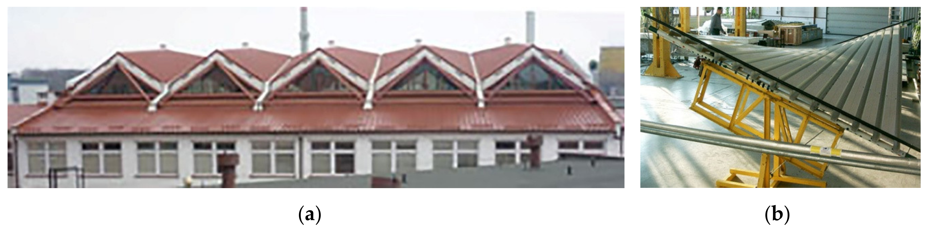
14]. The authors’ interests are complex roof structures created as a result of connecting many single shells into a single strip made of nominally flat, thin-walled folded sheets transformed elastically into shell forms by supporting them on roof directrices (
Figure 1) [
15,
16].
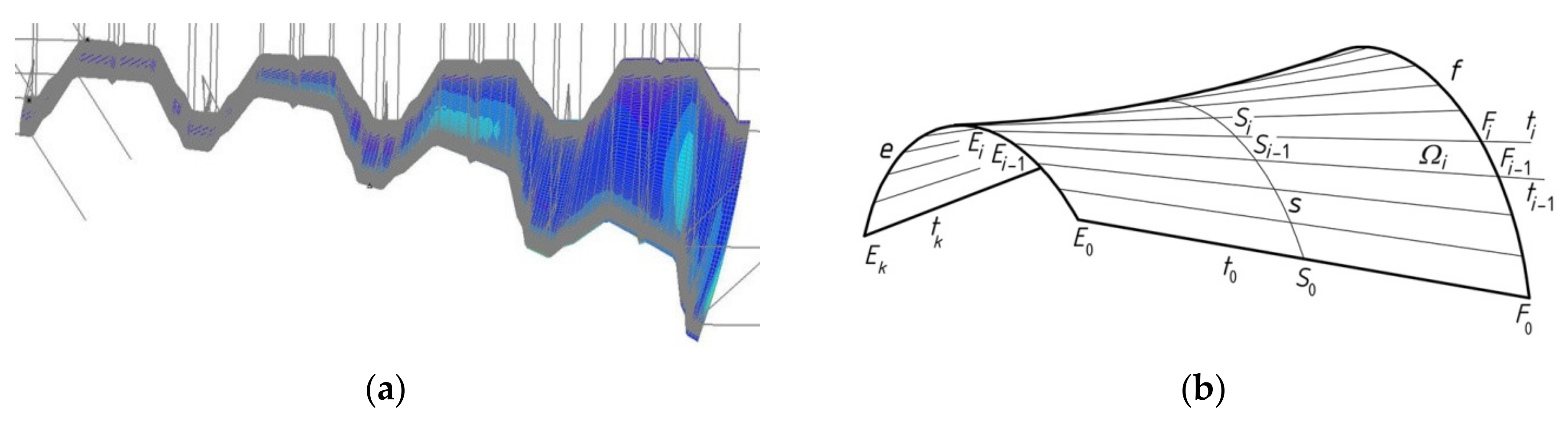
The designer ought to exploit the fact that folds have open profiles and they can easily adapt their deformed shell shape to the shape and mutual position of the roof directrices in a fairly wide range of transformation despite the complicated deformation of their walls causing considerable deformations and rotations of their cross-sections (
Figure 2a). The folded structure of such a shell allows all folds after transformation to be maintained straight [
17], so they are modeled in a simplified manner to engineering developments by means of ruled surfaces characterized by straight rulings
ti and the line of striction
s (
Figure 2b) [
18]. The rulings
ti model determines the longitudinal axes of all folds in a shell. The line of striction
s represents the contraction of all shell folds.
Prior to transformation the longitudinal axes of all folds in flat sheeting are straight lines parallel to each other and contained in one plane. During the transformation, they occupy strictly defined positions of skew straight lines, where the distances between them slightly and gradually decrease. The width of each transformed fold changes along its length, so that the fold contracts at half-length and expands at the opposite transverse ends. The longitudinal edges of each inner fold in the transformed shell are also skew straight lines. However, the longitudinal edges of the edge folds of the shell bend outwards (
Figure 2a) and must be stiffened with hot-rolled profiles or hollow sections [
19].
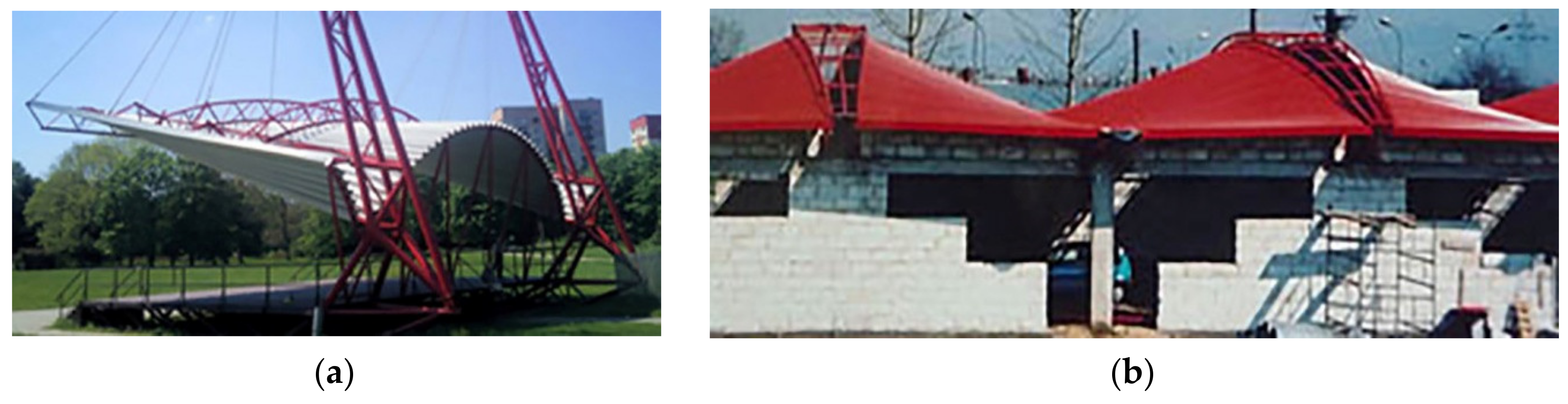
The roof directrices support the shell folds at their ends transversally to the directions of the folds. The shape and mutual position of roof directrices can be adopted relatively arbitrarily, so quite diverse forms of single, thin-walled roof shell sheeting can be achieved (
Figure 3) [
20].
In order to obtain effective forms of all folds in the transformed shell, the fold’s cross-sections are provided with free lateral deformation when assembling these folds into the shell directrices. Allowing such freedom for all shell folds enables the designer to optimize their initial effort to the lowest possible level. In this way, the folds change their widths and heights so that they contract at their half-length and equalize their positive width increments at their opposite transverse edges, i.e., along both transverse edge directrices. In the computation and modeling the shape of each fold, two conditions are used to optimize the form. One of them determines the location of the aforementioned contraction halfway along the length of each shell fold. The other one preserves the equality of the surface areas of two smooth models created for the same fold before and after its transformation [
21].
As a consequence of both conditions, the initial stresses resulting from the fold’s shape transformations can be designed as smallest possible, which allows the use of the shell folds as structural elements transferring dead and live loads onto the roof directrices. For this reason, thin-walled folded sheets are readily used for roofing. The skillful character of the shape transformations and freedom in defining roof directrices’ shapes can improve the attractiveness of the designed architectural forms [
22] and their sensitivity to a harmonious incorporation into the expected natural or built environments [
23].
During the shape transformations, shell folds are subjected to transverse bending and twist about their longitudinal axes along the length. In the case of curvatures used in shell roofs, the transverse bending of the folds does not significantly affect the level of their effort. The key is the twist, which, for engineering purposes, is assumed to be constant for the folds whose length ranges from 4 m to 15 m and height from 60 mm to 160 mm [
16,
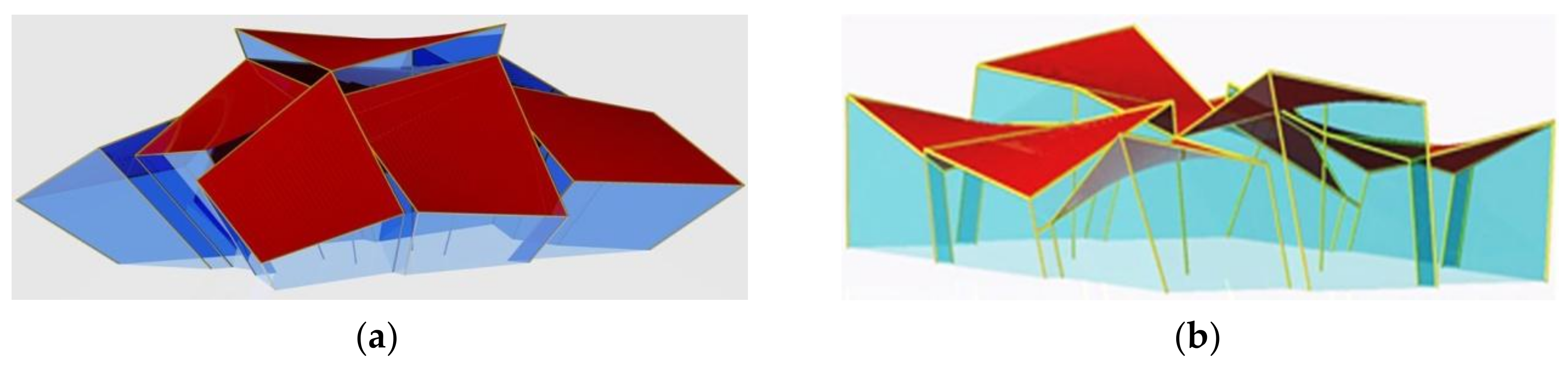
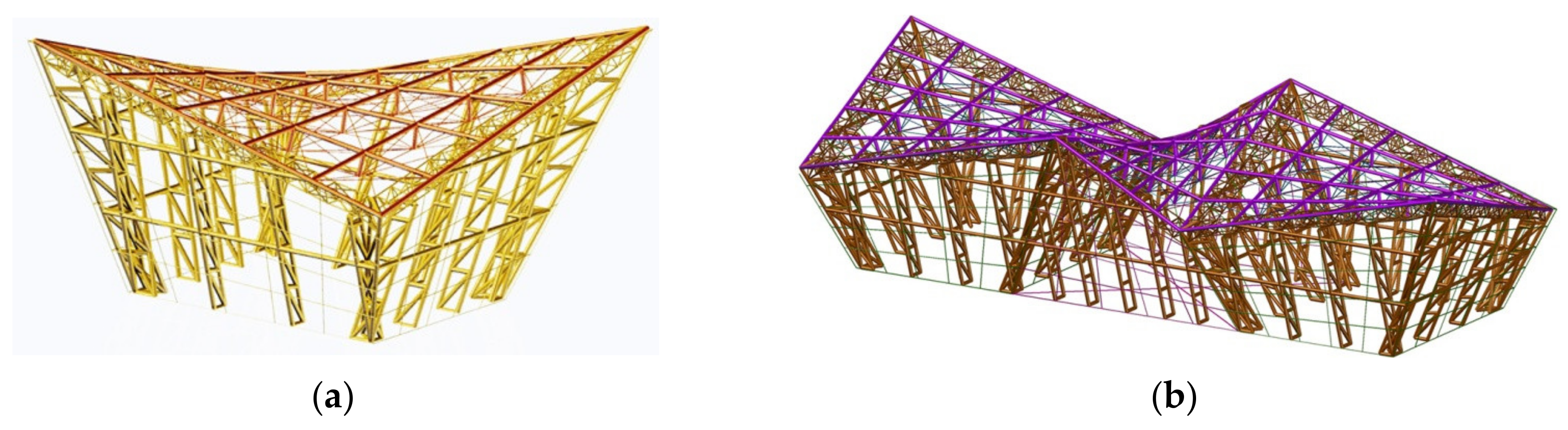
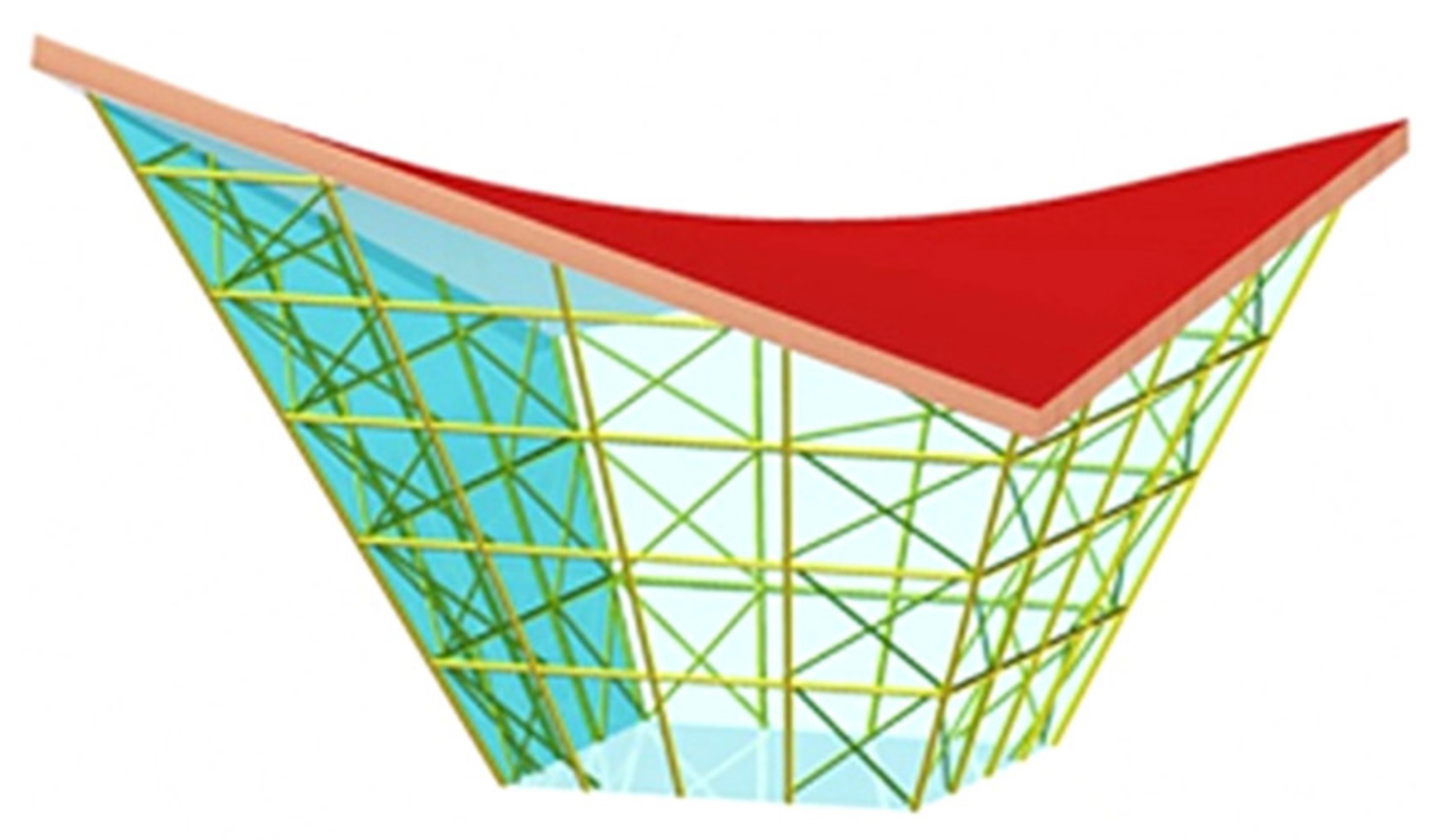
24]. In fact, the unit twist angle varies along the length of each twisted fold so that the greater the length of the shell folds the smaller the maximum recoverable unit twist angle that depends on the local elastic instability of the thin-walled flanges and webs of the fold. Therefore, for the cases of large and medium spans of roofs, individual shells are set together into roof structures (
Figure 4) and appropriate structural systems dedicated to them must be designed to stiffen these structures and entire buildings [
25,
26,
27,
28,
29,
30,
31]. Additionally, in order to make the building’s form more attractive, folded elevations, inclined to the vertical, are designed (
Figure 4) [
22].
The simplest way of creating such complex general free-forms of buildings is obtained by combining several complete free-forms, so that their selected walls are contained in common planes (
Figure 4) [
25,
32]. As a result, a single building structure roofed with a structure of few complete shells separated by edges (
Figure 1a and
Figure 3a) or additional areas completed with other covering elements (
Figure 3b), for example glass plates (
Figure 4), is obtained.
The interdisciplinary problems discussed and the complexity of their solutions require the designer to have professional knowledge and skills in the field of building, architecture, constructions and spatial reasoning in shaping accurate, and simplified engineering models and placing them in the Euclidean space [
33]. In order to support the designer’s activities in shaping the discussed free-forms and their structures, the authors’ main challenging tasks are reduced to the development of a parametric description of the shaping process of the aforementioned building forms [
25] and structural systems intended for them (
Figure 5). The developed description allows the authors to create their own computer applications, and in the future tutorials and guidebooks supporting the process of shaping the considered free-forms.
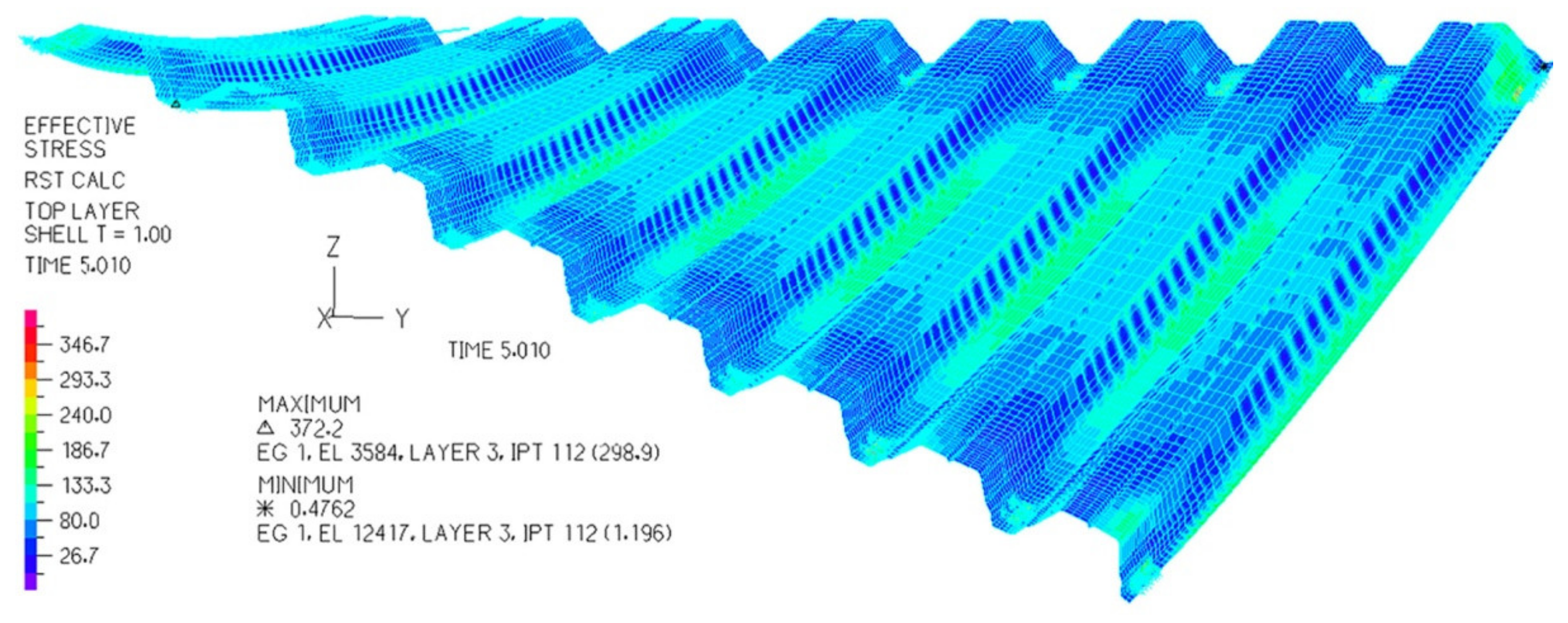
In present article, the activities of shaping such structures are limited to the parametric description of single and complex forms of general buildings and their roof structures. The description is oriented towards seeking for proportions defining various attractive, consistent general forms of roofs and façades. However, it is not focused on searching for different types of such forms and structures depending on the adopted sets of parameters. This different way is discussed by Abramczyk [
21]. The description also takes into account the results of experimental tests [
15,
16] and computer analyses [
34,
35] of shape changes and static strength work of all folds in such transformed shells (
Figure 6).
2. Critical Analysis
Forced shape transformations of folded sheets were accomplished by Gergely, Banavalkar, and Parker [
36] in the 1970s to create shallow hyperbolic paraboloid roofs and their structures named hypars. These sheet’s transformations are ineffective because additional forces acting transversally towards the fold’s longitudinal axes have to be used to reduce the widths of all shell folds to the arbitrary or poorly calculated lengths of the fold’s supporting lines along roof directrices [
37,
38]. Various configurations of hypar unit structures are proposed by Bryan and Davies [
39].
In the 1990s, Adam Reichhart started shaping corrugated steel sheeting for shell roofing, where all folds underwent big transformations into shell shapes. The transformations were named by Reichhart free deformations [
19]. He developed a simple method for geometrical and strength shaping of such shell roofs [
15]. According to his method, each roof shell sheet is modeled with a central sector of a right hyperbolic paraboloid limited by a spatial quadrangle [
40].
Jacek Abramczyk used the general Reichhart’s concept and created a new, more accurate method for shaping the transformed shell roofs. In addition, he assumed that the great freedom in shaping diversified transformed shell forms for roofing can be used to integrate the entire building free-form (
Figure 3). Consequently, he decided to incline and fold elevation walls to the vertical depending on the shape of shell roof and entire building [
18] (
Figure 1 and
Figure 2). He noticed that there is interdependence between the efficiency of the roof sheeting transformation and the location of its contraction along the length of each roof shell fold [
17]. This relation strongly affects the attractiveness of the entire form and the integrity of the shapes of the roof and elevation [
22].
Aleksandra Prokopska conducted multivariate interdisciplinary analyses of some consistent morphological systems that can be designed in harmony with the natural or man-made environments [
40,
41]. Her research involves many interdisciplinary topics needed to develop experience in shaping various attractive architectural free-forms [
24,
42].
Some main principles of shaping complete and compound innovative free-forms are the result of the cooperation between Aleksandra Prokopska and Jacek Abramczyk [
22]. On the basis of these principles they invented a preliminary version of a method for parametric shaping of the aforementioned folded plane and shell forms [
23].
3. Aims and Scope of the Paper
The main aim of the article is to present an innovative parametric description for shaping unconventional free-form building structures composed of a few complete free-forms positioned in one row and connected to each other with selected common plane elevation walls. This description should take into account the fact that in each individual form of such a structure the roof and façade forms should be integrated, which can be obtained by establishing appropriate relations between the dimensions, mutual position, and orientation of their main elements, such as edges and planes. These actions should be guided by the effort to obtain the smallest possible set of parameters that allow an intuitive prediction of approximate proportions between the dimensions of the characteristic elements of the roof and elevation of the subsequent individual forms in the structure under consideration.
In addition, the description should allow the modification of the shape and mutual position of all characteristic edges of the designed structure in order to obtain the possibility of shaping complex folded roof and façades. This action lets the designer conduct a creative search for very diverse unconventional forms characteristic of their current engineering or architectural activity and sensitive to the surrounding environments.
At the same time, the proposed description should allow for the
adoption of a reference parameter by means of which the expected proportions between elements of the structure, determining its internal consistency, attractiveness, and external sensitivity to the surrounding environment can be defined;
achievement of effective, i.e., optimal, shapes of all folds in the transformed roof shell in order to reach the smallest possible values of the effort of these folds and large deformations of the fold’s walls allowing for relatively high curvature of the roof shell;
fairly free adoption of the shape and position of roof directrices, which decisively affects the attractiveness of the shell roof form, the entire single free-form, and even the entire structure as well as its external sensitivity;
development of some original parametric computer applications supporting the designer’s activities in the field of creating simplified models of shell roofs and entire structures; and
development of parametric models for structural systems intended to the discussed types of the structures, in the future.
4. The Concept and the Range of the Work
In the parametric description presented in the sections that follow; the solutions of the issues appearing in the shaping process of different free-forms of buildings covered with folded roofs transformed to the shell form are presented. The actions and objects required for the above solutions are discussed on an example of shaping one single free-form and one structure of three free-forms.
In the first part of the description, a method for integrating the free-forms of roofs and façades by means of flat figures called reference polygons is proposed. The integration is achieved using a possibly small set of parameters defining some approximately selected values and proportions between the basic dimensions of these forms. Two separate plane parts of this polygon, corresponding to the spatial forms of roof and façade, are defined. At the same time, the polygon defines the slopes of the characteristic edges and planes of the roofs and façades to the horizontal base plane.
In the second part of the description, the aforementioned reference polygon Pr is expanded into a solid Σ, inter alia based on straight lines perpendicular to the plane of the polygon Pr. A very important role in shaping the final form of the sought-for structure is played by the closed spatial quadrilateral eaves consisting of four straight sections and four planes of façade walls inclined to the vertical. At this step, it is possible to modify two opposite eaves lines to the form of curved directrices of the roof shell.
In the third part of the parametric description further complete free-forms are defined, of which the resulting structure will be composed. In this article, single forms must have flat walls and a flat horizontal base contained in one initially adopted basic plane. The roof shell form is irrelevant to the above process of combining individual forms.
In the fourth part of the description, the created single free-forms are joined by common elevation walls in a single-row structure (
Figure 7). In the presented example, the roof consists of three single shells joined into one continuous structure, where the complete shells are separated by common edges disturbing the smoothness of the entire roof structure.
In the fifth part, the presented parametric description allows modifying the forms of the roof and façade of the achieved structure in a certain, but not very large, range. The significant effect of this modification is a folded plane-walled façade structure and multisegment roof structure. At this step, the thickness and overhang of the roof shell are defined.
In one of the parts of the above description, a regular elevation pattern must also be defined as the sum of the appropriately arranged flat strips of the façade glass panels. This pattern must be integrated with the general form of the structure and its individual elements.
Finally, visualization of the example structure is presented, which confirms the correctness of the assumptions, actions, and objects used in the discussed parametric description, and the wide possibilities of obtaining various free-forms and their structures. This visualization also illustrates that the structures built on the basis of this description have the internal integrity of the form of their elements and the external sensitivity to the natural environments. The method of creating the visualized structure is presented in the subsequent sections of the article.
5. Intuitive Parametric Shaping of General Forms of Free-Form Buildings
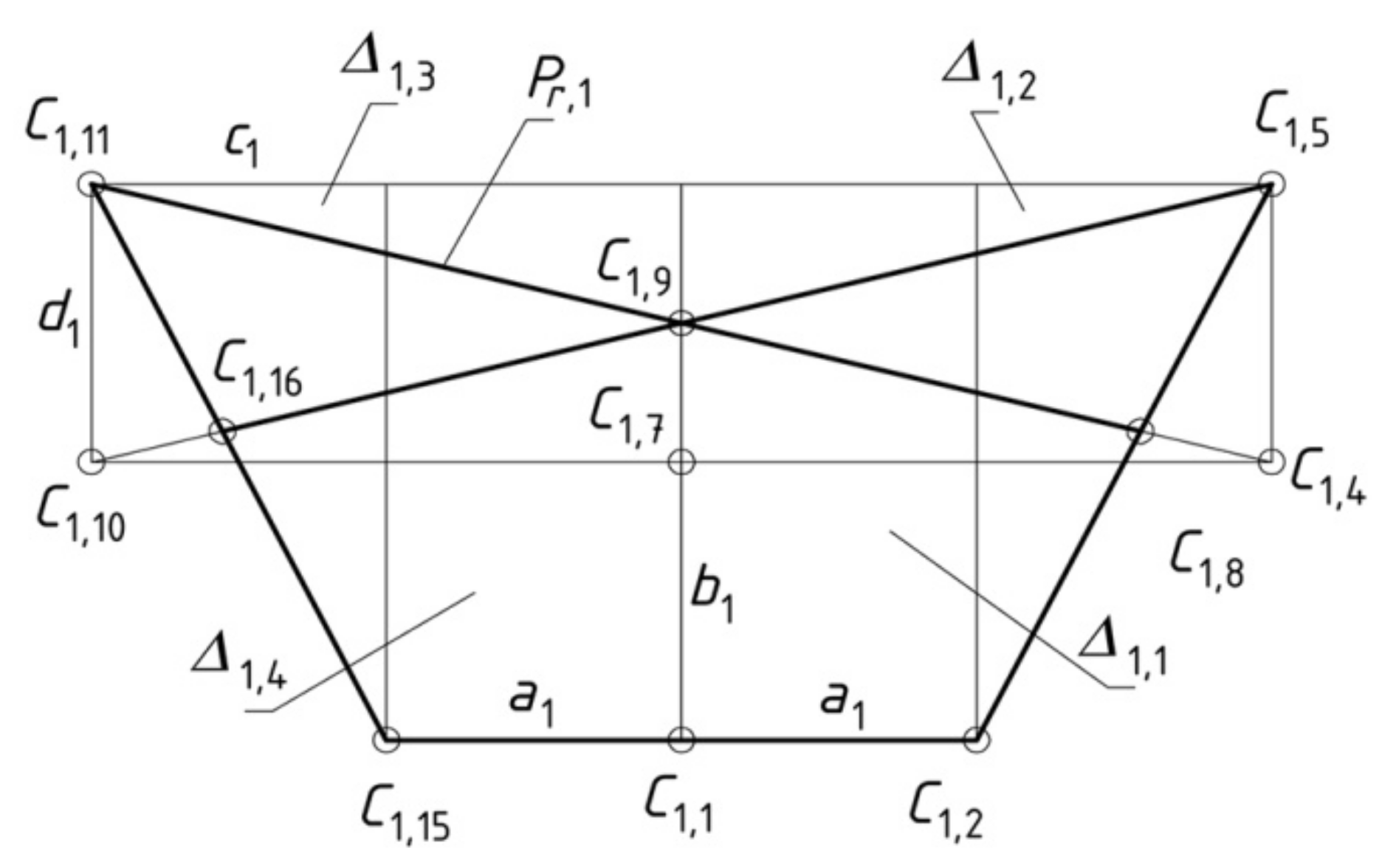
In order to design a general building free-form using the proposed method, the following action should be performed. The values of the following parameters describing transverse dimensions of the designed free-form are adopted. Eight parameters:
a1 = |
C1C2|,
b1 = |
C2C3|,
c1 = |
C5C6r|,
d1 = |
C4C5|,
a2 = |
C1C15|,
b2 = |
C15C17|,
c2 = |
C6C11|, and
d2 = |
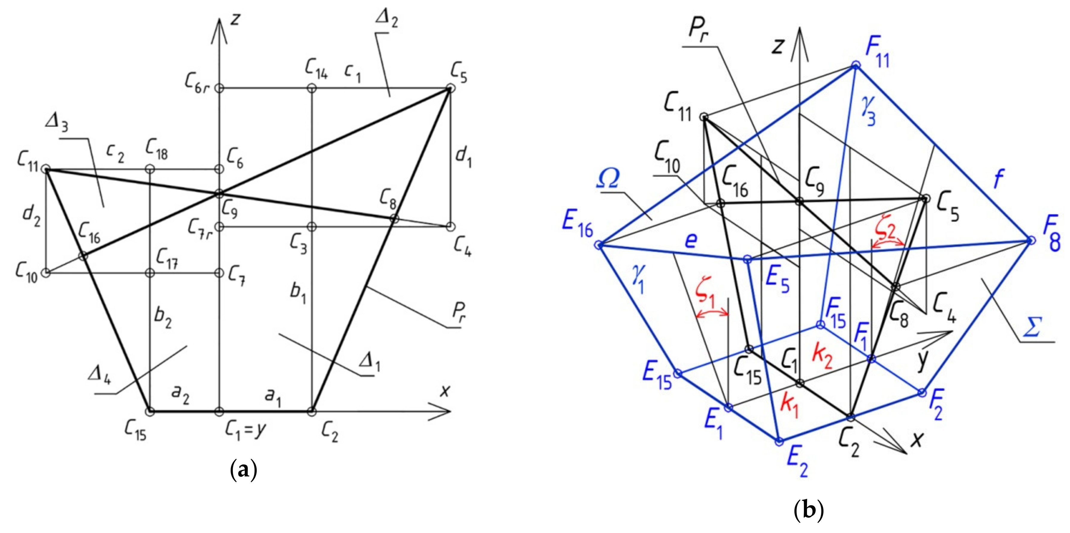
C10C11| determine four auxiliary rectangles
Δi (
i = 1 to 4) (
Figure 8a). For example,
Δ1 =
C1C2C14C6r and
Δ2 =
C4C5C6rC7r. The rectangles
Δi are located in a very specific manner so that each of
Δi has one edge contained in the
z-axis. The rectangles
Δ1 and
Δ4 are the initial approximation of the elevation form. The
Δ2 and
Δ3 rectangles are the initial approximation of the roof form.
Two rectangles—Δ1 and Δ4—have the common vertex C1 located at the origin of the adopted orthogonal coordinate system [x, z]. Points C8 and C16 are the intersection of the respective segments C4C11 ∩ C2C5 and C5C10 ∩ C11C15.
On the basis of the sum
Δ of the above four rectangles
Δi, a plane reference polygon
Pr is built, so that its vertices are identical with some selected rectangle’s vertices. These vertices are as follows:
C1,
C2,
C5,
C8,
C9,
C11,
C15, and
C16 (
Figure 8a). The shape integration of the roof and elevations is ensured by means of the proper proportions between the areas of triangles
C8C5C9 and
C9C16C11 and quadrangles
C1C2C8C9 and
C1C9C16C15 of
Pr. These proportions express the real proportions between the size of the roof shell and elevation wall under consideration, and between the inclination of the eaves and elevation walls to the vertical. Thus, in this step of the presented description, these eight parameters should be employed.
In the next step, the reference polygon
Pr is extended into a spatial free-form
Σ sought (
Figure 8b). Therefore, six straight lines perpendicular to the plane of
Pr should be passed through the vertices:
C2,
C5,
C8,
C11,
C15, and
C16. Vertices
E2,
E5,
E16,
F2,
F8,
F11, and
F15 of
Σ are determined as the points of the intersection of the above six straight lines and two planes
γ1 and
γ3 of two gable walls of
Σ. In this step four additional parameters are employed: two parameters—
ζ1 and
ζ2—defining the dihedral angles of the inclination of planes
γ1 and
γ3 to the vertical, respectively, and two parameters—
k1 and
k2—defining the distance of
E1 and
F1 from the plane (
x, z) (
Figure 8b).
To define the above figure
Σ by means of one independent variable
a, the main proportions, included in
Table 1, are adopted. In addition, the last two parameters are tg(
ζ1) = 0.429 and
ζ2 =
ζ1, where
ζ1 – measure of the angle between
γ1 and (
x, z) and
ζ2 – measure of the angle between
γ3 and (
x, z).
The coordinates of its characteristic points are given in
Table 2, and the visualization of the architectural form related to the discussed general form is shown in
Figure 9. The aforementioned proportions ensure that this configuration of
Σ meets the expectations of the visual attractiveness of the designed free-form and its internal integration.
The obtained spatial quadrangle
E5F8F11E16 represents the eaves of the roof shell. Two opposite segments
E5E16 and
F8F11 of the aforementioned quadrangle (
Figure 8b) are called roof directrices
e and
f. The directrices are here two straight lines.
In the end, an elevation pattern is defined by means of two families of straight lines (
Figure 9). The parameters describing the pitch, position and orientation of the elevation pattern should be defined. In the presented examples, only two parameters defining the pitch in the horizontal and vertical direction are employed. The roof thickness and cantilever protruding out of the elevation planes are two other parameters that affect the attractiveness, internal integration of the building form and external integration of the form with the built or natural environment.
6. Elevation Shaping
Regular elevation patterns together with general shapes and proportions between the main parts of the free-form buildings like elevations, roofs, and structural systems play an important role in improving the visual attractiveness of these forms and their harmonic integration with man-made environments. These patterns are designed by means of visible elements supporting elevation glass plates or filling the areas between these plates. The pitch, orientation, and position of these elements should be analyzed. Members of structural systems may also be the visible elements forming the regular pattern.
The models presented below take account of the thickness of the roof and regular pattern of elevations (
Figure 10). The main object of this step is a model taking account of the aforementioned properties of roof and elevations. They are sufficiently accurate in engineering developments.
Its surfaces, planes, lines, and points are the main auxiliary geometrical elements. Intersections, displacements, and rotations of these elements allow all building elements as finite sectors, sides, and edges to be modeled and arranged relative to the building construction axes.
The mutual location of the roof and elevations results from the structure and overall dimensions of the general building form. Therefore, the new parameters used in this step are
u—the thickness of roof,
v—the roof overhang outside the outline of elevation walls, and
w1, w2—the pitch (may also be position and inclination) of regular elevation pattern in horizontal and vertical direction.
The range of possible regular elevation patterns considered in the present paper is limited to two configurations shown in
Figure 10 and
Figure 11. This is due to the main aim of the paper concerning the use of the parametric description for creative shaping innovative consistent spatial building free-forms and their structures relevant to the built and natural environments.
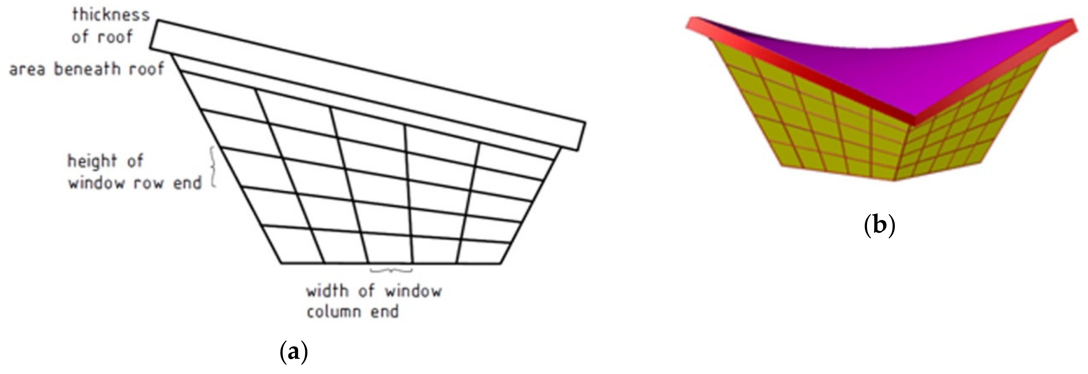
The above first pattern considered (
Figure 10) is reduced to only one type formed from five strips of glass plates positioned in the direction close to the vertical and five strips located in the direction close to the horizontal base plane. The presented pattern forms a network of quadrilateral plane glass “cells” changing equally their widths and heights.
The thickness of the roof shown in
Figure 8, together with the unfilled with glass elevation part located beneath the roof create a strip whose height is also important in relation to the dimensions of the roof and elevations, which also affects the process of architectural shaping. The constant division of elevation areas with the orthogonal or, in particular, the diagonal lines of the pattern may produce a fine impression of harmony and integration of all elements and the entire free-form. The compatible constant or variable changes of very often improve the aforementioned features of the designed building.
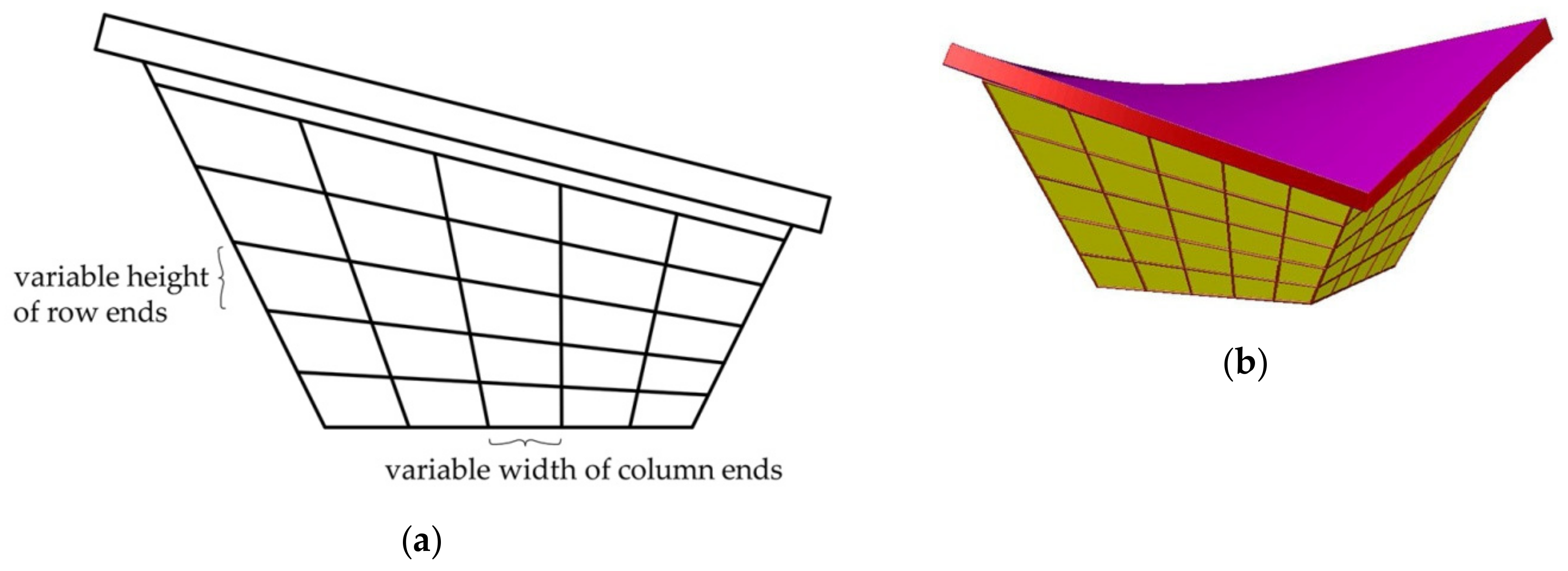
The second configuration of the elevation pattern is presented in
Figure 11, where the widths of the subsequent horizontal and vertical strips change. The size of the horizontal strips changes in the vertical direction. The size of the vertical strips changes in the horizontal direction. Both changes can positively affect the user’s wellbeing.
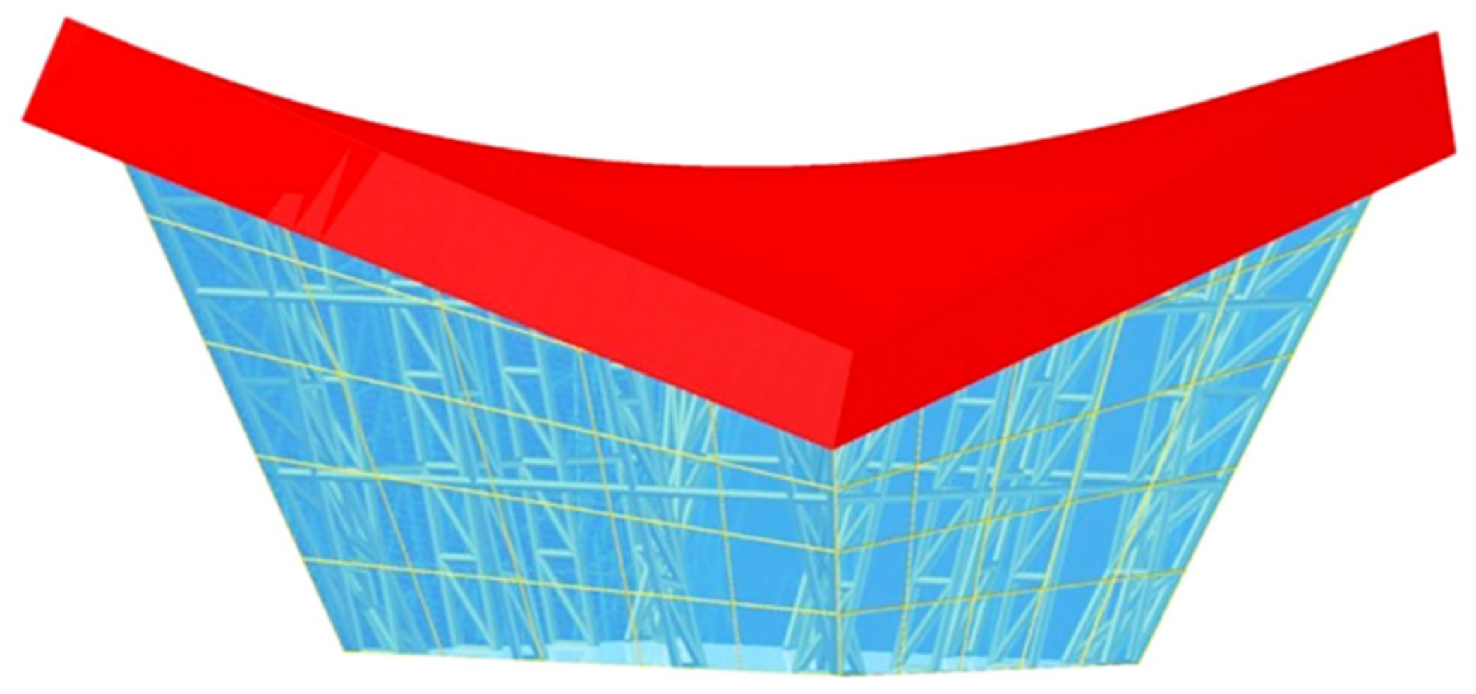
Thin elements between glass plates can perform an important function improving the visual attractiveness of the elevations from the outside. The structural system can be gently truncated inside of a building to enhance the internal attractiveness. If it is visible by a user from the inside of the building, then the user’s comfort of wellbeing can be improved. It can also be translated outside the building (
Figure 12), which can change radically the user’s visual impression. Structural systems and regular elevation patterns may be designed independently so that each can perform different functions: structural or visual by the observation from the inside or outside of the building designed.
7. Attractive Shape Proportions for Free-Forms
To obtain satisfactory forms of buildings it is necessary to analyze some proportions between the size, orientation and inclination of all main elements of the designed building such as roof, elevations, and their elements like eaves and edges. Attractive complete forms characterized by integral forms of the roof, elevations, and eaves can be developed as the result of assuming the strictly defined relationships between the discussed parameters, for example the ones included in
Table 3 and
Table 4, which leads to the reference polygon shown in
Figure 13. The properties are adopted according to the guidelines and functional dependence defined by Abramczyk [
22]. The result of the above dependencies is that the sum of four rectangles
Δi is a flat figure
Δ symmetrical towards the vertical
z-axis. The reference polygon
Pr, created on the basis of
Δ, is also
z-axis-symmetrical. The architectural free-form shown in
Figure 12 was achieved employing the aforementioned procedure, parameters from
Table 3 and
Table 4 and tg (
ζ =
ζ1 =
ζ2) = 0.25.
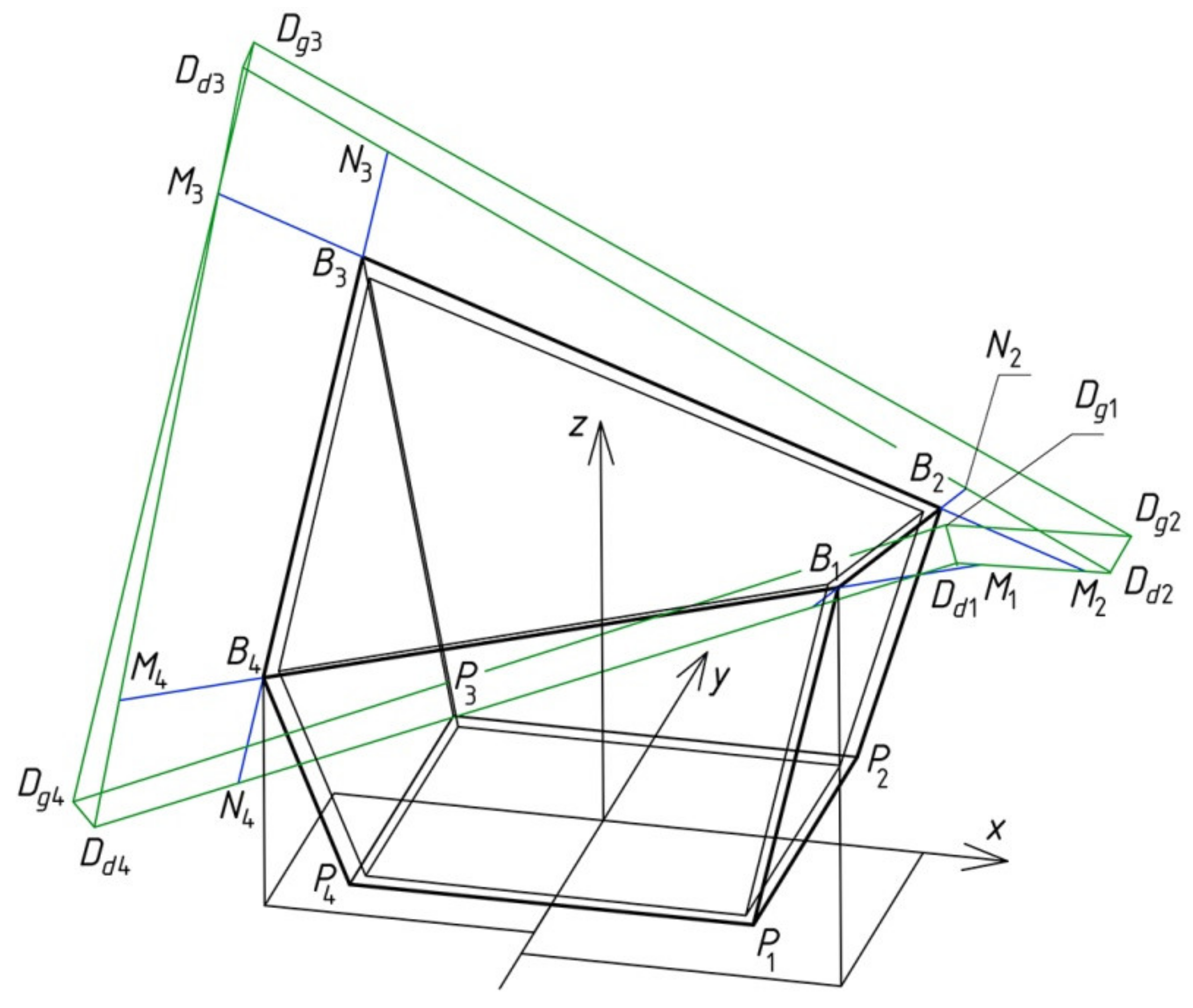
The parameters
v = |
M1B1| = |
M2B2| = |
M3B3| = |
M4B4| = |
N1B1| = |
N2B2| = |
N3B3| = |
N4B4| = |
Dd1Dg1| = |
Dd2 Dg2| = |
Dd3Dg3| = |
Dd4 Dg4| and
u = |
Dd1Dg1|, included in
Table 3, determine the overhang and thickness of the shell roof (
Figure 14). To achieve attractive proportions, only nine parameters—
a1, b1, c1, d1, k1,
ζ1, u,
v, w1 =
w2—are needed in the case of shaping symmetrical free-forms. The width of the elevation walls is irrelevant in the present example.
In addition, the roof shell can be translated in the vertical direction as was done for the case of the free-form shown in
Figure 15 and the structure presented in the next section. The coordinates of the characteristic points of such architectural form shown in
Figure 13 and
Figure 15 are given in
Table 5.
The calculation of the supporting conditions for the subsequent folds in the example shell, shown in
Figure 15, should be carried out according to the algorithm proposed by Abramczyk [
21] in [
21]. On the basis of the supporting conditions obtained, the lengths of the supporting lines for the subsequent folds along the roof directrices should be calculated using the computer application written by Abramczyk [
22] discussed in [
21].
Some functional dependencies between the above parameters can be a basis for the estimation of the innovation and attractiveness of these forms to be designated. The proportions should result in the following;
the inclination of each elevation wall to the vertical relates to the slope of all eaves to the horizontal base,
the sizes of roof and elevation are close to each other,
the expected proportions between the height and width of the building as well as the roof’s thickness along eaves ought to be maintained,
the curvature and contraction of the roof shell correspond to the building’s height measured along each of four oblique elevation edges, and
the shape of the visible part of the building’s structural system relates to the elevation pattern.
8. Compound Free-Form Structures
The proposed parametric description also concerns creating complex structures composed of many individual forms with shared elevation walls. Few individual free-forms can be arranged in one row or in rows and columns (
Figure 4) [
23]. The structures investigated in the present article are arranged only in one row. They are determined by means of inseparable symmetrical reference polygons
Pr,i created subsequently in accordance with the algorithm described previously for single
Pr.
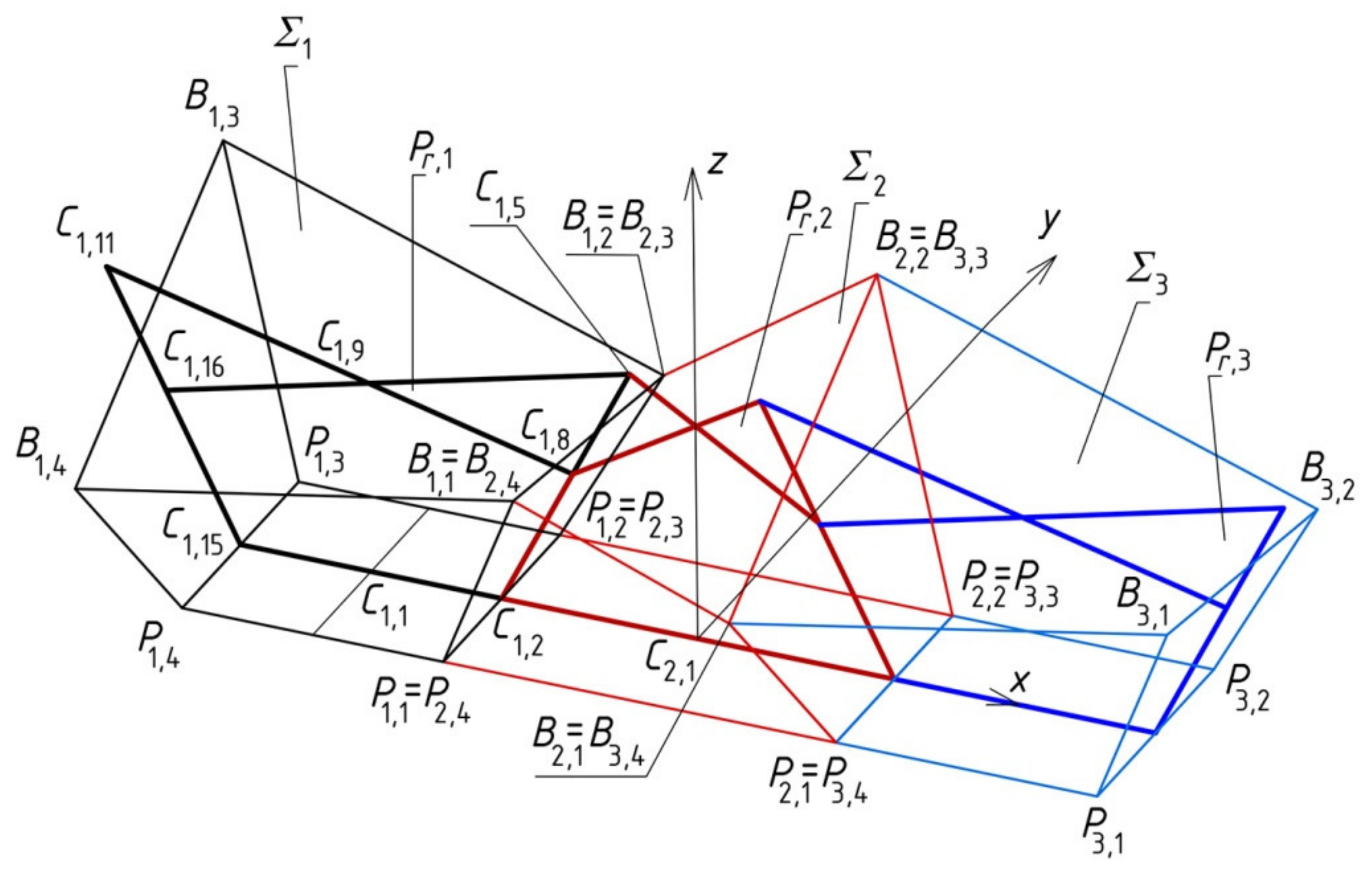
The sum
Σ of such three complete forms
Σi (
i = 1 to 3) having common planes of the elevation walls and arranged in one direction is presented in
Figure 16. The actions related to the construction of form
Σ start with the determination of three auxiliary flat reference polygons
Pr,i (
i = 1 to 3) placed in the same vertical plane.
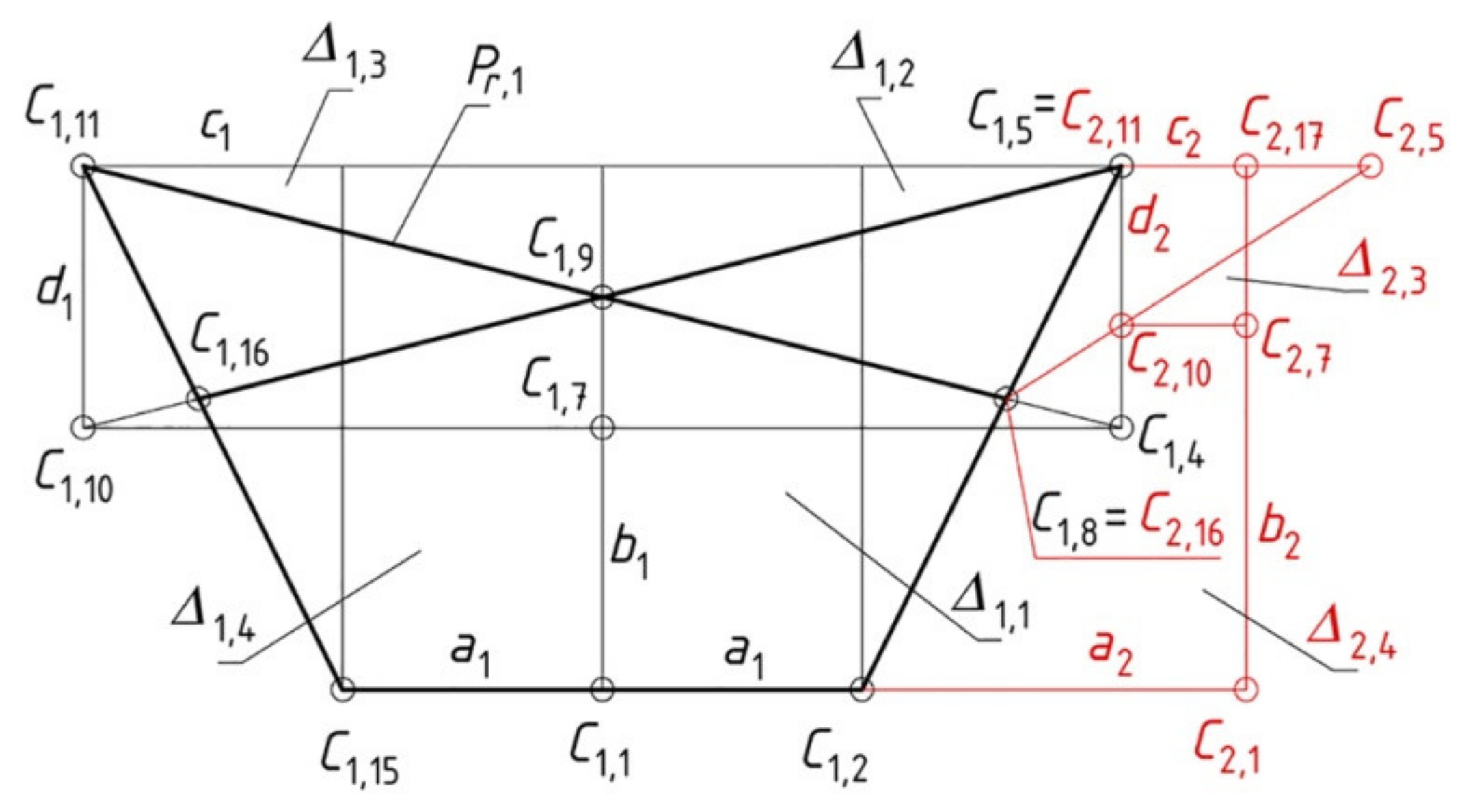
According to the proposed algorithm,
Pr,1 is created on the basis of four parameters:
a1,
b1,
c1, and
d1 defining four rectangles
Δ1,j (
j = 1 to 4) (
Figure 17). Next, the value of the parameter
a2 should be adopted in order to construct point
C2,1 on the extension of the straight line (
C1,2,
C1,15). Point
C2,17 is constructed at the intersection of the line passing through
C2,1 and perpendicular to the straight line (
C1,2,
C2,1) with the straight line (
C1,11,
C1,5). Because
C2,11 is similar to
C1,5, the value of parameter
c2 is calculated as the length of section
C2,11C2,17. In addition,
C2,10 is the intersection of the straight line passing through
C2,5 and
C2,16 =
C1,8 with the straight line (
C1,5,
C1,4). Point
C2,5 is symmetrical to
C1,5 about the axis (
C2,1,
C2,17). The value of parameter
d2 can be calculated as the length of segment
C2,10,
C2,11. Rectangles
Δ2,3 and
Δ2,4 can be created on the basis of the aforementioned points. The last parameter is
b2 =
b1 +
d1 -
d2.
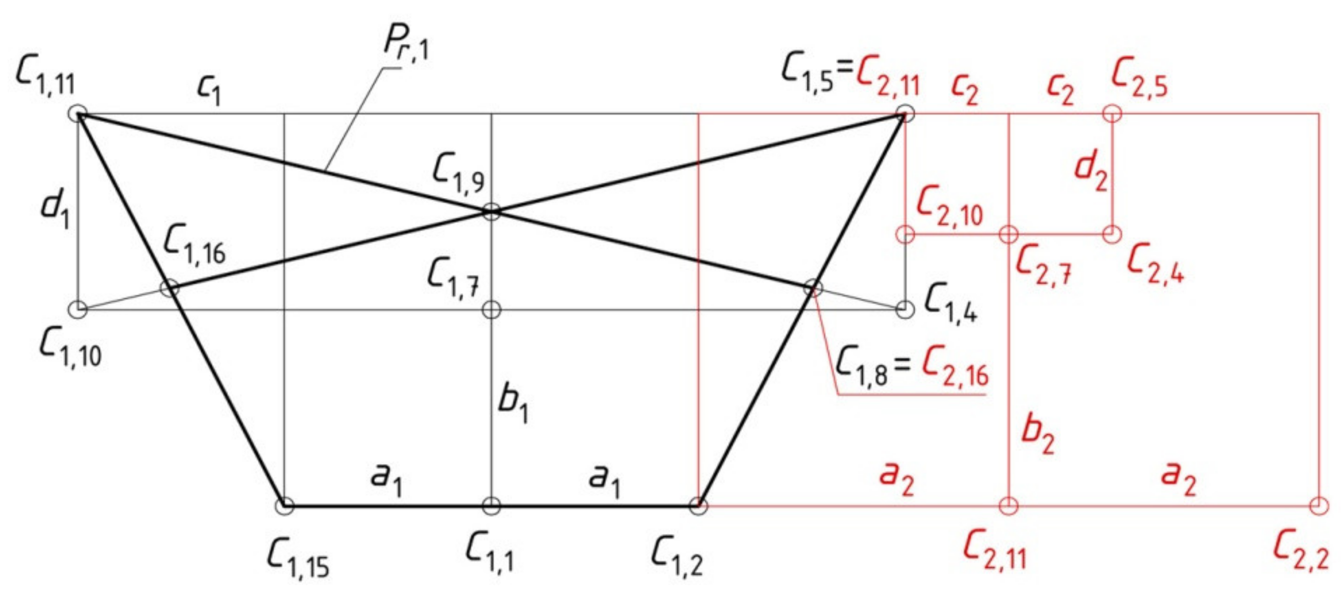
Parameters
a2,
b2,
c2, and
d2 define both rectangles
Δ2,3 and
Δ2,4 and rectangles
Δ2,1 and
Δ2,2, which are symmetrical to the previous ones (
Figure 18). Summing up, the value of parameter
a2 should be adopted, whereas the values of
c2,
b2, and
d2 have to be calculated.
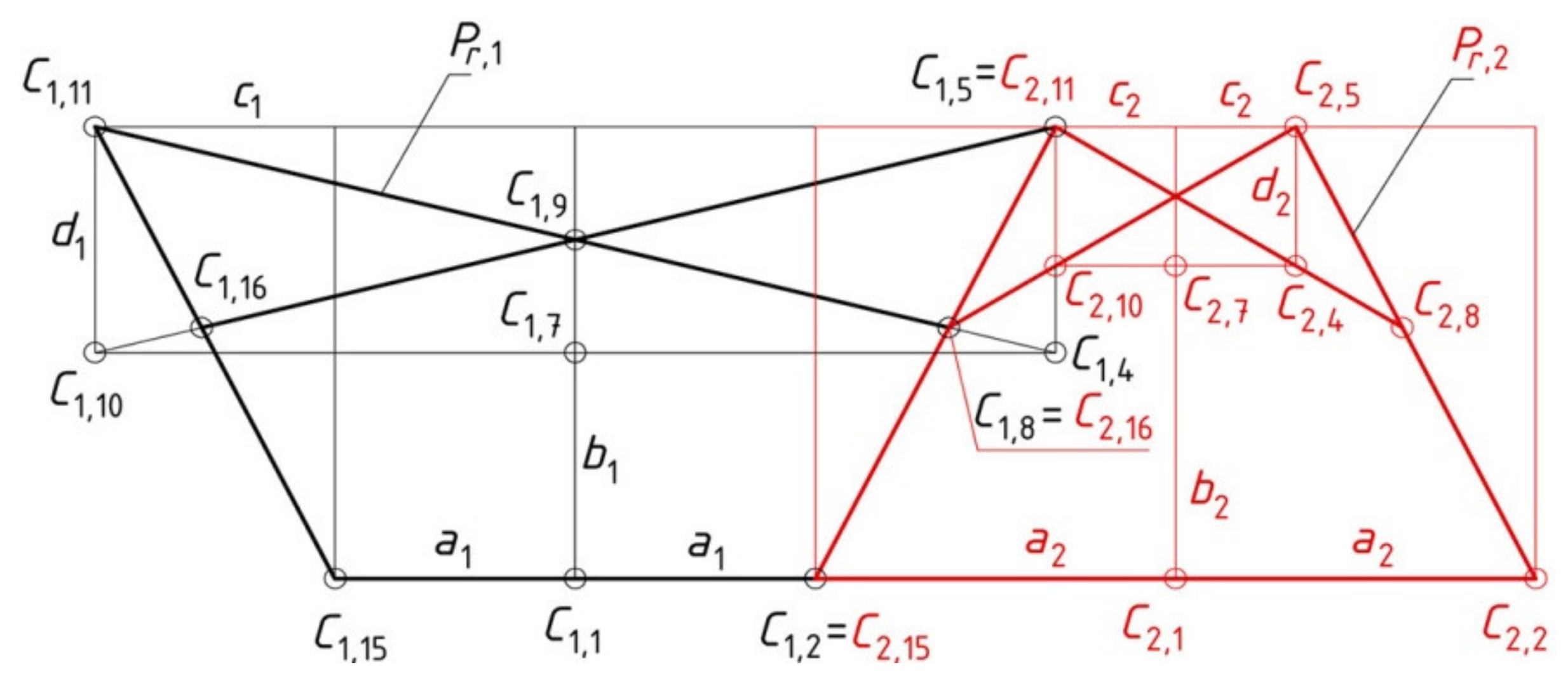
On the basis of rectangles
Δ2,i (
i = 1 to 4), including their vertices, polygon
Pr,2 is constructed (
Figure 19). Polygons
Pr,1 and
Pr,2 have one common side
C1,2C1,5.
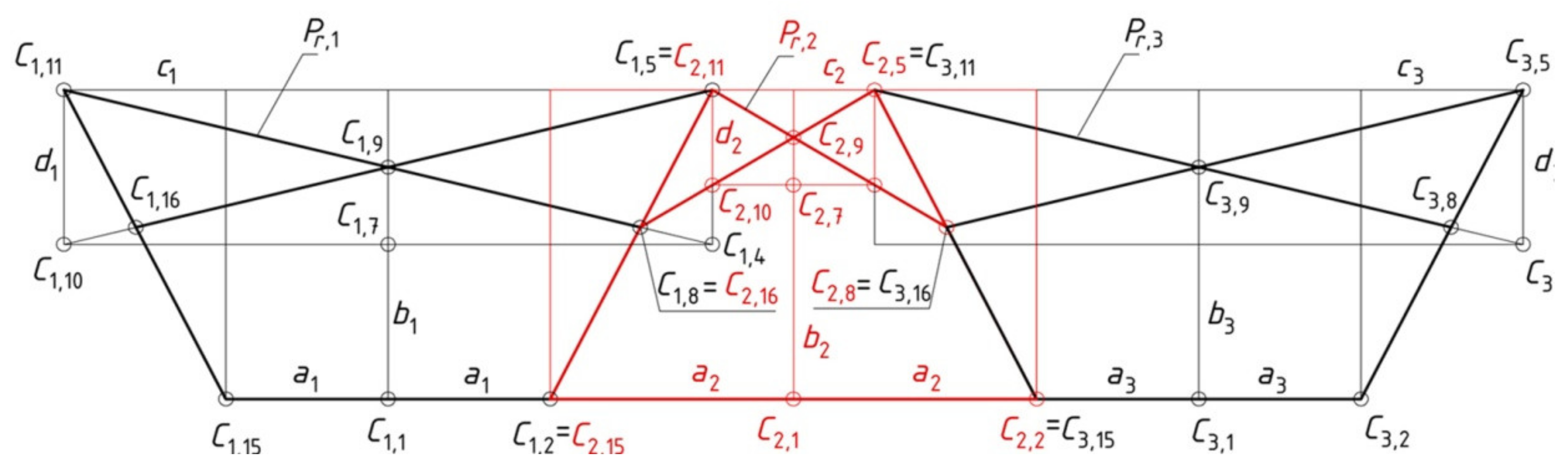
In the same way as
Pr,2, the last polygon,
Pr,3, is created (
Figure 20). The creation of
Pr,3 requires adopting the value of
a3 and calculating the values of
b3,
c3, and
d3.
The coordinates of the selected characteristic points
Ci,j (for
i = 1 to 3 and
j = 1 to 16) of the discussed complex reference polygon
Pr = Σ
Pr,i shown in
Figure 20 are given in
Table 6. The parameters used are
a1 =
a3 =
a,
b1 =
b3 =
a,
c1 =
c3 = 2
a,
d1 =
d3 =
a, where the values of the main parameters
a, b, c, d are given in
Table 1. In addition,
a2/
a = 1.5 is adopted and
b2/
a = 1.385,
c2/
a = 0.500, and
d2/
a = 0.615 are calculated. Based on the whole polygon
Pr = Σ
Pr,i (
i = 1 to 3) (
Figure 20), a spatial form
Σ, which is the sum of
Σi, is created (Figure 16) using the constructions presented in
Section 5. The other parameters are:
k1 =
k2 =
k3 =
a and
ζ1 =
ζ 2 =
ζ 3 = 14.0362°.
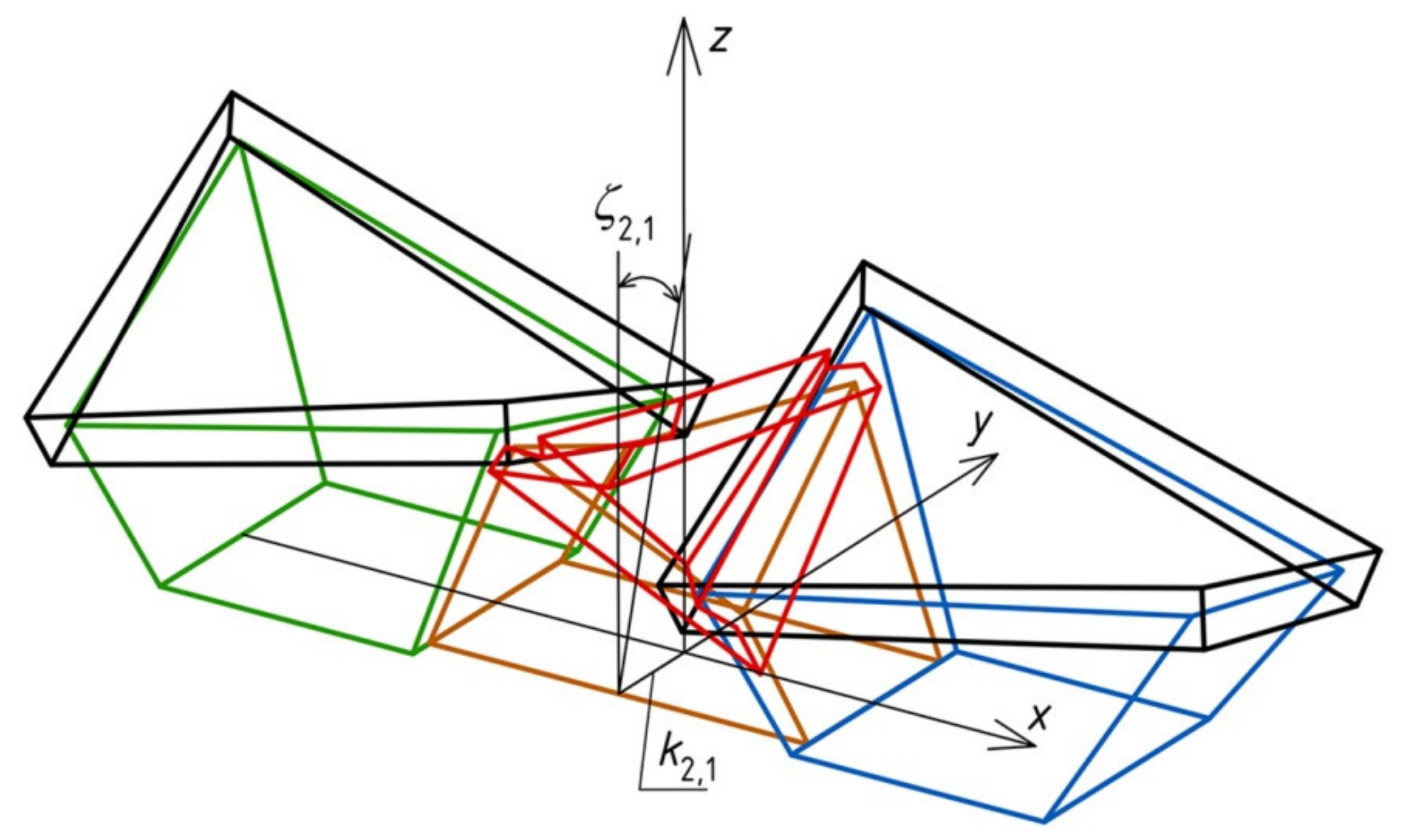
Finally, the created form
Σ is transformed into a complex structure
Σw which is characterized by folded elevation walls and shell roof structure (Figure 21). This modification of
Σ into
Σw can be done in two ways. The first way is based on displacements and rotations of two opposite gable wall planes of the form
Σ2 and division of the compound shell roof of
Σ into three complete shell sectors creating the discontinuous shell roof structure. The displacements and rotations depend on the values of
k2,1 <
k1,1 =
k3,1, and
ζ2,1 adopted for the form
Σ2. The value of
ζ2,1 may be equal to or different from the values of
ζ1,1 and
ζ3,1. In the presented example, the discussed structure
Σw is
z-axis-symmetrical:
k2,1 = 0.2
a and
ζ2,1 = 9.0362° (Figure 21). The coordinates of the characteristic vertices of this structure, shown in
Figure 21 and
Figure 22, are given in
Table 7.
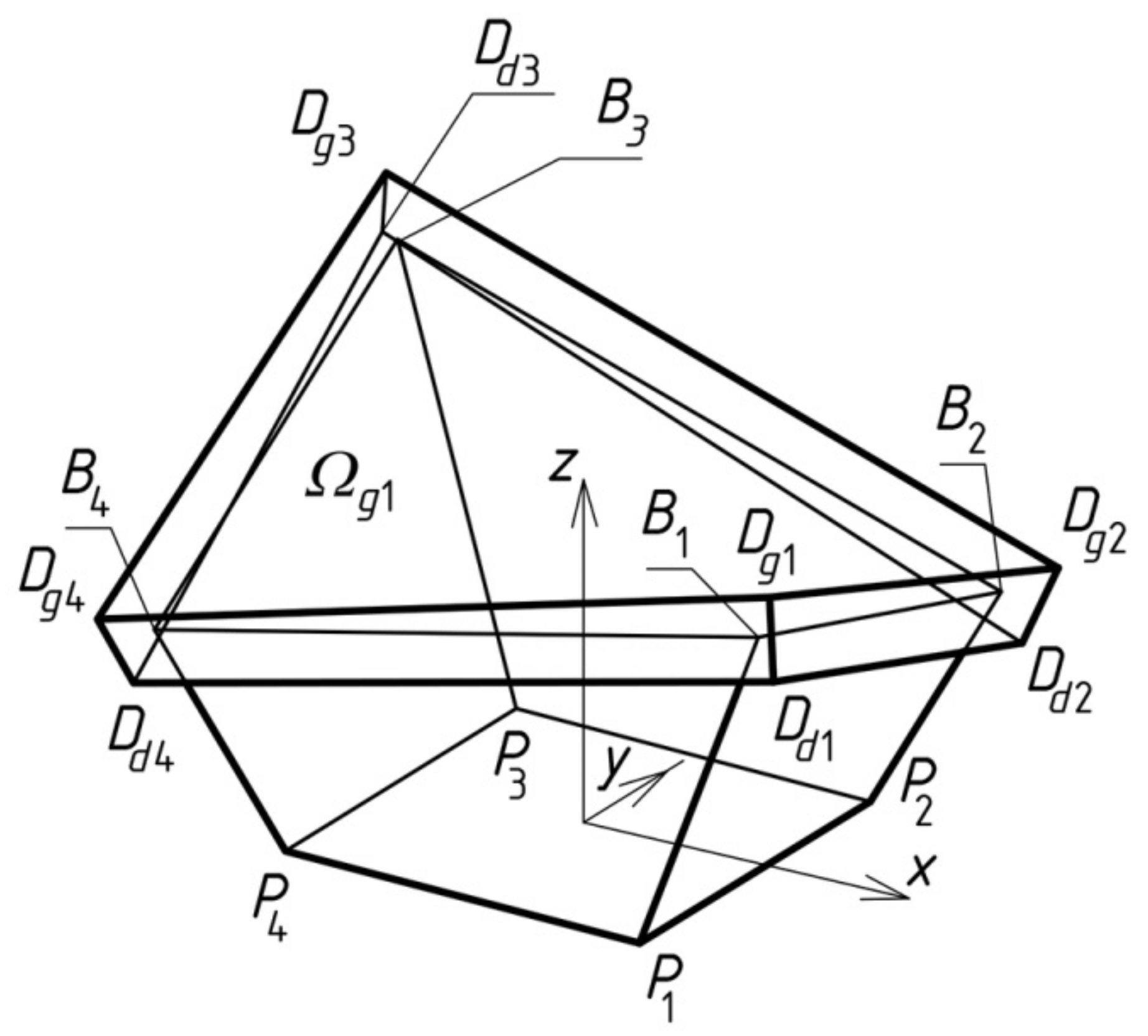
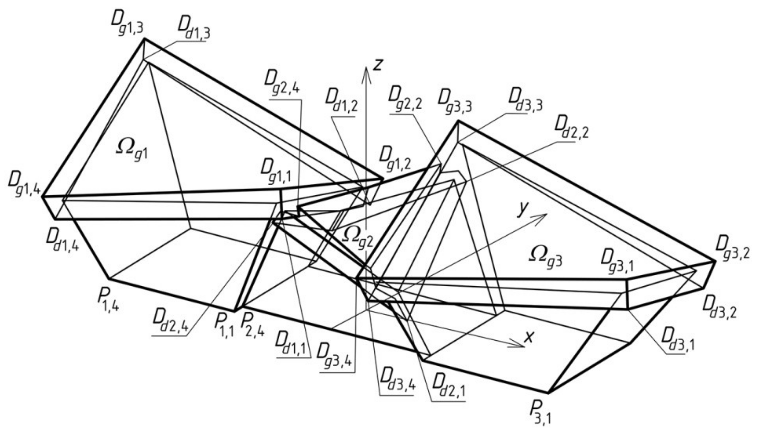
Points Dgj,i (for i = 1–3, j = 1–4) are the vertices of three closed edge lines of the upper surfaces of three complete roof shells Ωgi forming the shell roof structure. Points Ddj,i are the vertices of three closed edge lines of the lower surfaces of the same shell roof structure.
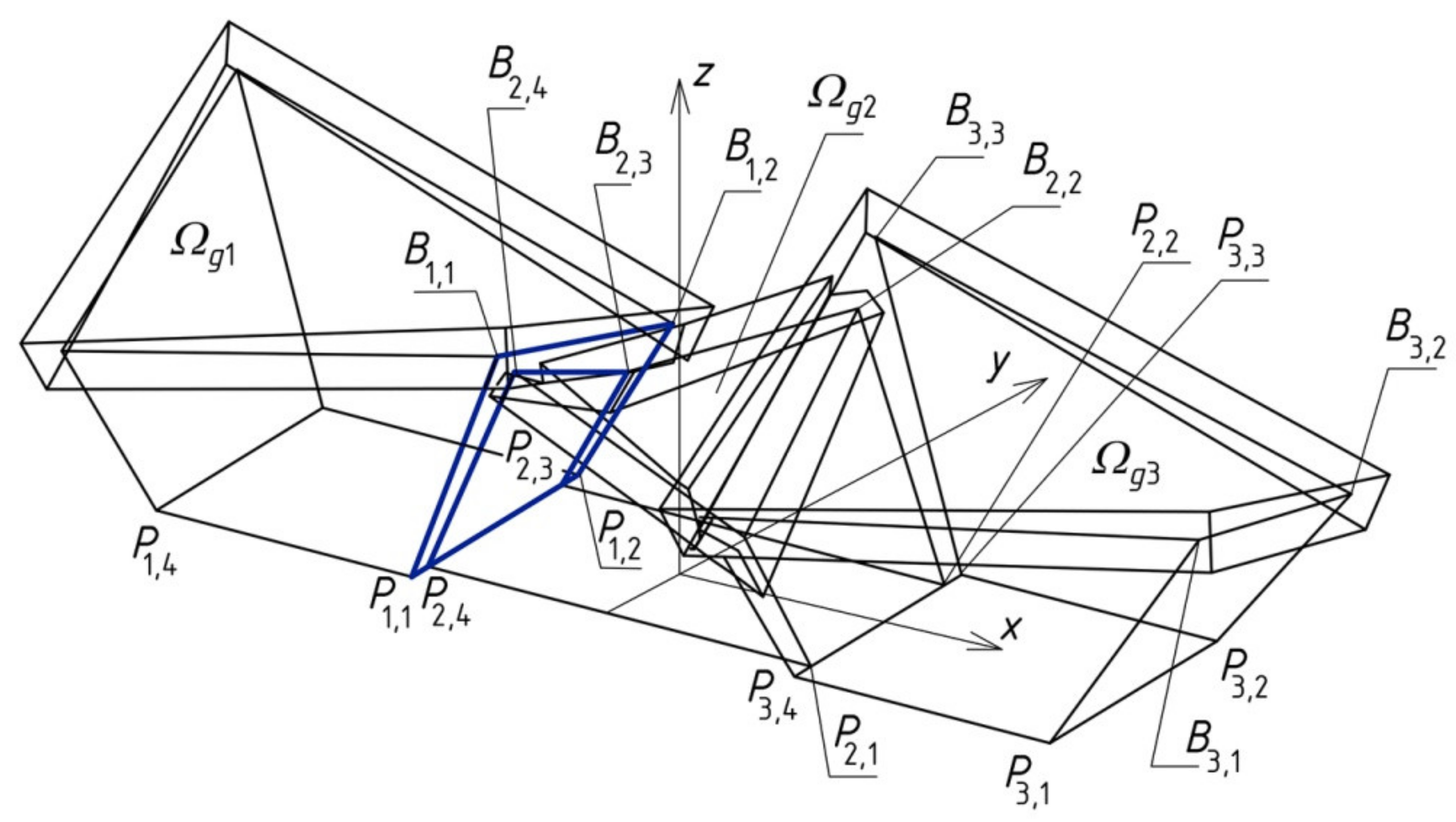
For the cases of symmetrical structures,
Σ, the aforementioned modification, can be performed by means of stiff motions of three edges
P1,1B1,1,
P1,2B1,2, and
B1,1B1,2 belonging to the shared wall plane of
Σ 1 and
Σ 2. In the presented example (
Figure 23), the symmetry of
Σ 2 towards
z-axis ensures that the created gable wall of
Σ 2 is plane.
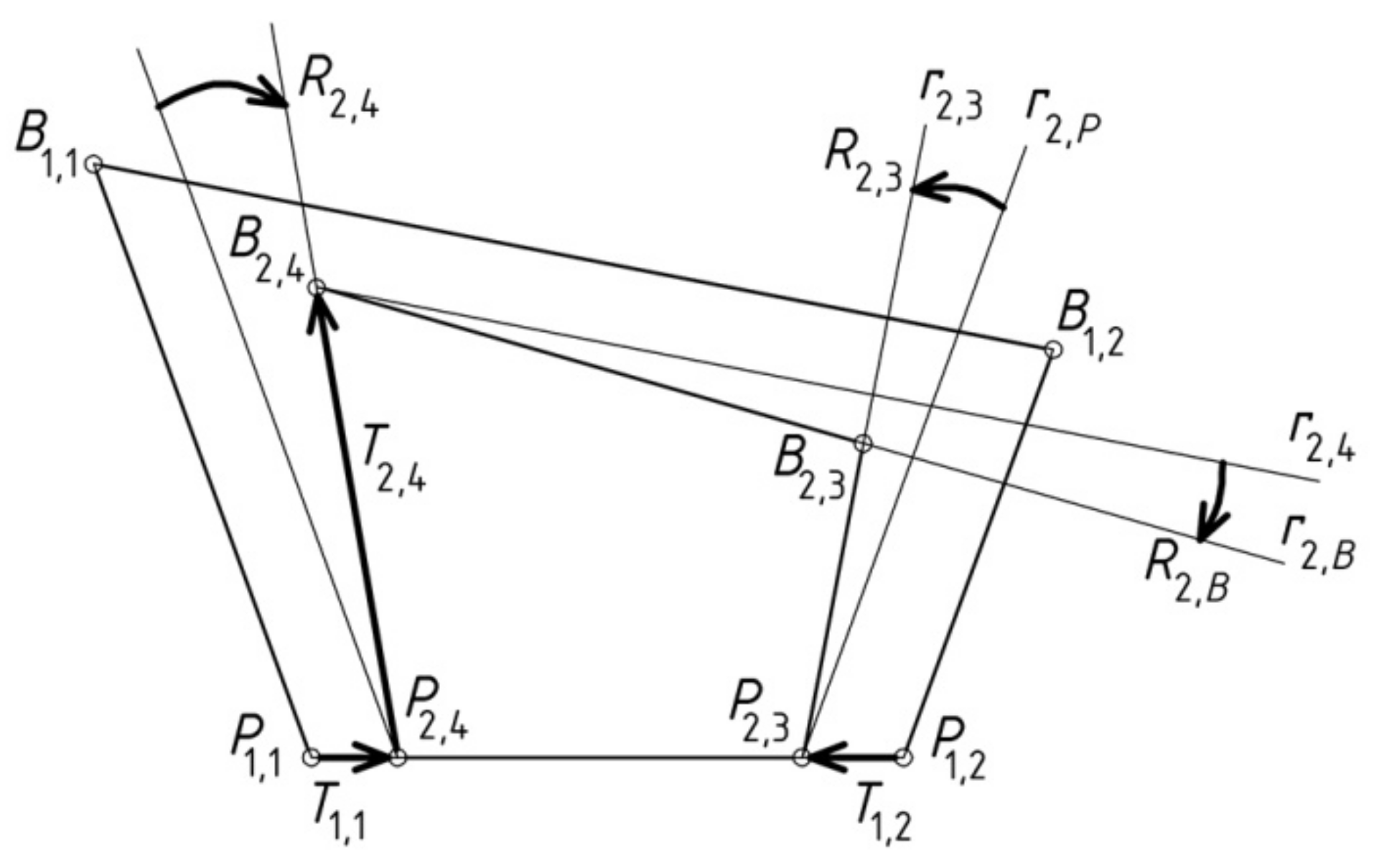
In order to obtain the positions of points
P2,4, B2,4,
P2,3, and
B2,3 (
Figure 24) the following transformations must be performed. First, translation
T1,1 and rotation
R2,4 of the line (
P1,1,
B1,1) is executed. Next, the translation
T2,4 of point
P2,4 along the obtained straight line is done to obtain the position of point
B2,4.
The position of point
B2,3 can be achieved as a result the intersection of two straight lines
r2,3 and
r2,B determined as follows. To obtain
r2,3, the straight line
r2,P parallel to (
P1,2,
B1,2) and passing through
P2,3 must be transformed using rotation
R2,3 around
P2,3. To obtain
r2,B, the straight line
r2,4 parallel to (
B1,1,
B1,2) and passing through
B2,4 must be transformed using rotation
R2,B around
B2,4. For symmetrical forms, the restriction
R2,4 =
R2,3 has to be met in order to obtain flat gable wall of
Σ 2. The values of the aforementioned stiff motions are given in
Table 8.
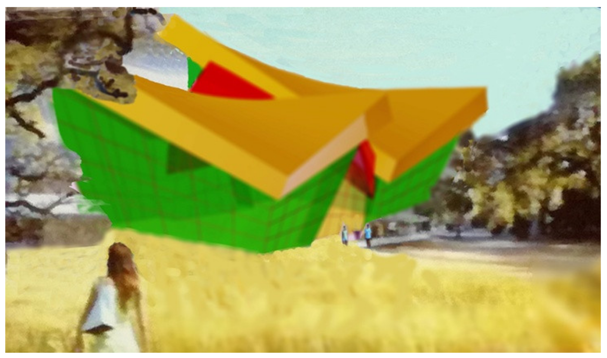
On the basis of the above
Σw structure, the architectural free-form shown in
Figure 25 was visualized. It has an attractive shape and spring and summer colors, which makes it sensitive to the natural environment. The regular pattern of its elevation walls created in the form of thin dark lines evenly distributed on the outer surface and running in two orthogonal directions is marked in a very sensitive way. The coloring of the two spatial lateral free-forms of the complex architectural structure harmonizes with the colors of the natural environment. The yellow color of the minor middle part of the structure refers to the color scheme of the lateral parts of the roof structure and the natural environment. The red color of the middle roof shell stands out from the coloring of the previously mentioned parts and the natural environment.
9. Conclusions
The novel parametric description of shaping architectural free-forms of buildings oriented to the shape integration of their roofs and façades is discussed in the article. The description uses the smallest possible set of parameters defining the general forms and regular elevation patterns of these forms. The values of these parameters are the lengths or angles of slopes of the selected roof or façade elements like edges and surfaces.
In the case of symmetrical general forms of buildings, only four parameters {a, b, c, d} describe the geometrical properties of a flat reference polygon, which roughly define the proportions between the size of the roof and façade elements. In order to define the entire general form, the description requires two additional parameters—ζ and k—defining the shape of this form in the direction perpendicular to the direction highlighted previously and also parallel to the building horizontal base. In the case of unsymmetrical general forms of buildings, another six parameters {a2, b2, c2, d2, ζ2, k2} must be adopted.
The possibility of adopting one leading parameter called a reference parameter as only one independent variable defining some basic proportions between selected roof and elevation elements is discussed. The proportions are defined using functions helpful in searching for similar types of interesting architectural free-forms. More comprehensive studies of the aforementioned issues seem to be targeted at an assignment of the ranges in which the values of the selected parameters and their proportions are changed to such groups of free architectural forms characterized by similar properties.
An important role in the aforementioned description is played by the modeling process of the nominally plane folded sheeting transformed into shell shapes, which is based on the shape and mutual position of two roof directrices that can be adopted fairly arbitrarily in the planes of façade walls. On the basis of the directrices, the arrangement and shapes of the folds in the transformed shell, as well as the spacing of the points fixing the transformed fold’s ends to the shell directrices, have to be precisely calculated. Because of the relatively complex iterative mathematical calculations combined with the above two conditions, optimizing the fold’s shapes it is necessary to use the original application developed by the present authors in the Rhino/Grasshopper program.
The application of the proposed parametric description to create a free-form structure composed of three individual forms connected with shared elevation walls and arranged in a single row has been demonstrated. In this case, the proportions between the dimensions of the roof and façade are defined by three reference polygons contained in one common plane and three groups of parameters. The values of some selected parameters of these groups are taken as identical due to the common base plane and common selected walls of the individual component forms of the created structure. The constructed flat complex reference polygon structure Pr, composed of three reference polygons Pri connected with each other, must be extended to a spatial form in the direction orthogonal to the plane in which it is contained. This action requires the designer to be able to use the spatial reasoning in locating various simplified models of engineering objects in the three-dimensional space. To obtain the integrity of the form of a building the dimensions, the orientation and position of its roof elements, such as eaves, and façade elements, such as the edges of the walls, are interrelated by means of Pr.
Ultimately, the spatial structure can be modified to a form characterized by a folded façade and roof structure in order to make it more sensitive to the existing natural or built environments. Such a modification is presented on an example of a specific structure embedded in the accepted natural environment. The visualization of this structure is shown in one of the presented figures, and its measurement characteristics are included in the respective tables.
It is advisable to develop a method of shaping regular elevation patterns on the façade wall planes, of variable pitch, location, and orientation. The authors intend to develop a concept of shaping shell façade walls by means of cylindrical and conical surfaces.
The authors have also initiated work on parametric shaping of structural systems dedicated to the considered complete architectural free-forms and their structures. Specific structural systems stiffening the essential edges of the discussed free-forms are necessary because of the complex structure of the roof and façade forms as well as the varied inclination of their elements, such as the oblique edges of the eaves and façade.
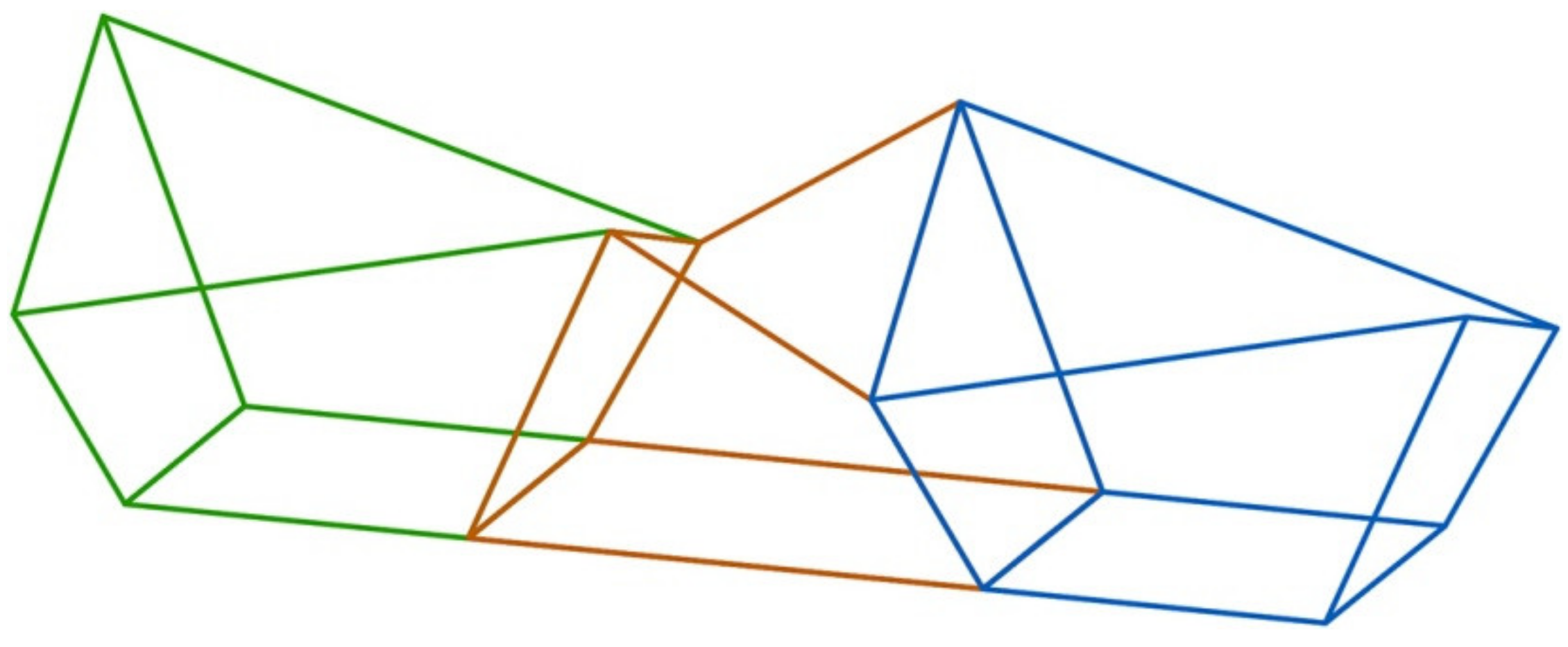
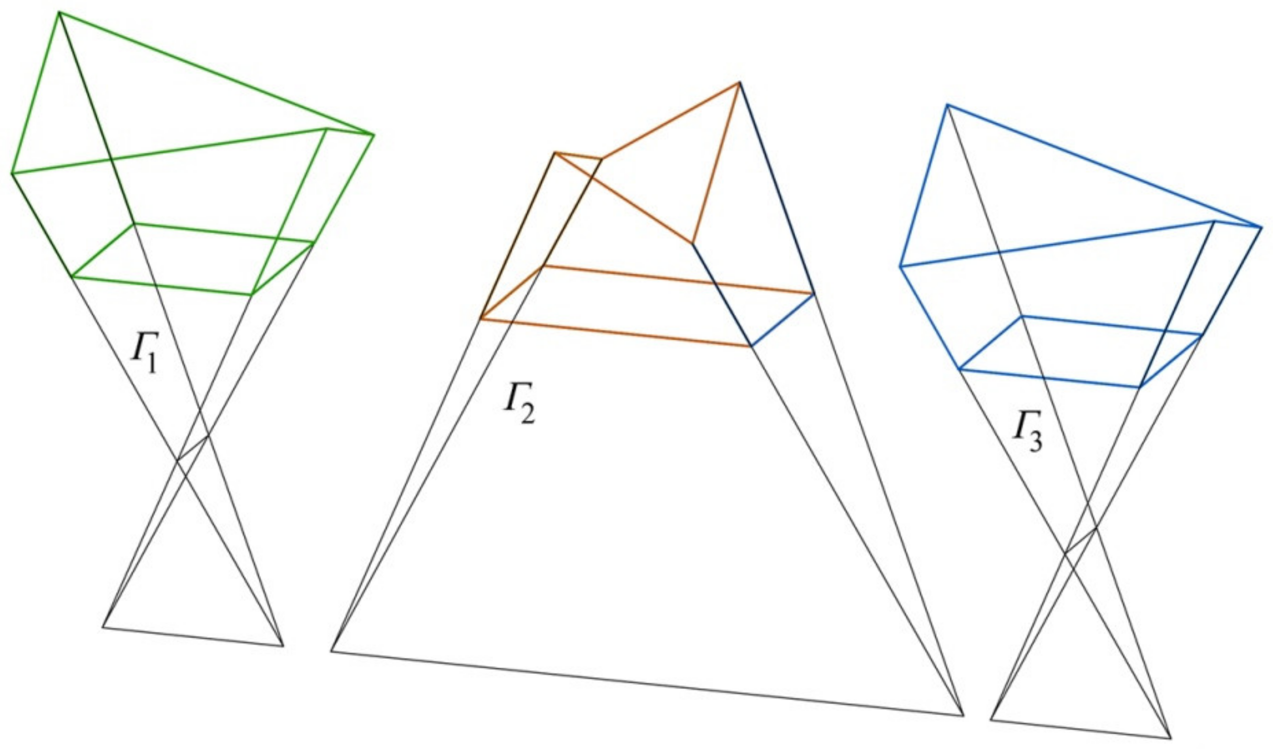
In the authors’ previous papers, a different approach to the creation of spatial structures composed of many individual free-forms roofed with structures composed of many individual transformed folded shells was presented. The main aim of the aforementioned papers was to use the wide possibilities offered by combining many reference tetrahedrons
Γi (
Figure 26), such as the ones used for the case of the presented example structure
Σ presented in
Figure 16,
Figure 17,
Figure 18,
Figure 19,
Figure 20,
Figure 21,
Figure 22,
Figure 23,
Figure 24 and
Figure 25.
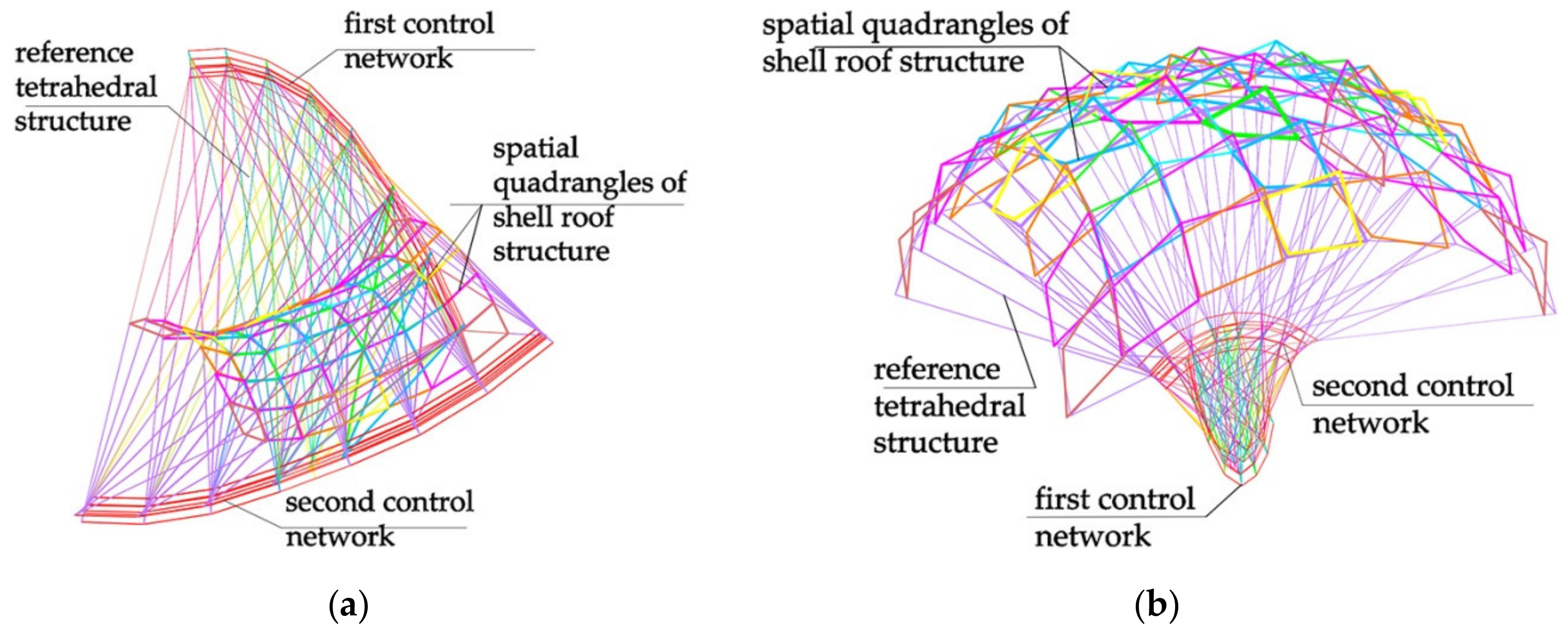
Different types of these reference tetrahedrons may be joined into one complex spatial reference network (
Figure 27). Some of the types are presented in this article. The spatial network is used to give the curvature and overall dimensions of the complex roof shell of the architectural structure being sought. The spatial cells of such a network—named reference tetrahedrons—help in locating single free-forms of various specific dimensions of their roofs and façades.


