Article

Experimental Research on Using Form-stable PCM-Integrated Cementitious Composite for Reducing Overheating in Buildings

by
Sayanthan Ramakrishnan
1,*,
Jay Sanjayan
1 and
Xiaoming Wang
1,2,3
1
Centre for Sustainable Infrastructure, Faculty of Science Engineering and Technology, Swinburne University of Technology, Hawthorn, VIC 3122, Australian
2
Department of Civil Engineering, Monash University, Melbourne, VIC 3800, Australia
3
The State Key Laboratory of the Cryospheric Science, Northwest Institute of Eco-Environment and Resources, Chinese Academy of Science, Beijing 100091, China
*
Author to whom correspondence should be addressed.
Buildings 2019, 9(3), 57; https://doi.org/10.3390/buildings9030057
Submission received: 8 January 2019 / Revised: 21 February 2019 / Accepted: 22 February 2019 / Published: 4 March 2019
(This article belongs to the Section Building Materials, and Repair & Renovation)

Abstract

:
This paper investigates the potential of using form-stable phase change material (FS-PCM) integrated cement mortars in building envelopes to prevent overheating and to improve summer thermal comfort. The FS-PCM integrated cement mortar was applied as the interior surface plastering mortar of a full-scale test hut and compared with identical test huts built on cement plasterboard (OCB) and gypsum plasterboard (GPB). The test huts were exposed to outdoor climatic conditions, and indoor thermal behaviours were continuously monitored throughout the summer period. The effects of PCM in reducing the overheating was analysed by the intensity of thermal discomfort (ITDover) and frequency of thermal discomfort (FTDover) for overheating during the summer days. The comparison between different test huts showed that the application of PCM integrated cement mortars reduced the peak indoor temperature by up to 2.4 °C, compared to GPB and OCB test rooms. More importantly, the analysis of overheating effects revealed that at lower intensive thermal discomfort levels, FS-PCM largely reduces FTDover. As the intensity of thermal discomfort increases, the reduction in ITDover becomes dominant. At highly intensive thermal discomfort levels, the reduction was neither apparent in the intensity of thermal discomfort nor the period of discomfort.

1. Introduction

According to the International Energy Outlook (IEO2017), the building sector accounts for 21% of the world’s energy consumption in 2015 with a projected increase of 32% by 2040 [1]. Oceania (Australia and New Zealand) stands as the third major consumer among Organisation for Economic Co-operation and Development (OECD) countries and the energy consumption per capita in these countries is projected to increase from 2015 to 2040, while the United States and Canada are projecting a significant reduction by 2040. Energy intensive services, including space heating and cooling, holds the biggest share at roughly 50%, and consequently, building energy efficiency measures and technologies have become an area of significant research interest.
The modern building envelopes encompass lightweight construction materials along with large glazed surfaces to allow fast construction processes and to increase the aesthetic appearance of buildings. Furthermore, they are effectively designed to have proper space conditioning controls, high insulation performance, minimised infiltration, and high-performance windows and doors. However, one major limitation of these building designs is that they have very little amounts of thermal capacity and are more prone to be overheated during hot summer days [2,3]. This leads to a large fluctuation in indoor temperatures and requires high energy demands to meet thermal comfort conditions in buildings. Before resorting to the use of air-conditioning to meet the thermal comfort in modern buildings, possible ways to enhance the thermal capacity must be studied. In this regard, the use of thermally enhanced building envelope components, such as incorporating phase change materials (PCMs) into building elements, can be considered as a promising solution to reduce heating/cooling energy demands [4,5,6,7]. PCMs have the ability to change their state within a defined temperature range to store and release a large amount of thermal energy using their latent heat capacity. The additional advantages of PCMs are high volumetric heat capacity and small temperature variations during the phase transition process. Due to these advantages, PCM can be considered for enhancing the thermal energy storage (TES) capacity of modern buildings without a large addition to the building mass [8,9].
The incorporation of PCM into building elements to enhance building energy efficiency has been extensively studied using experimental, analytical and numerical approaches. PCM-incorporated building components such as wallboards [10,11], tiles [12,13], bricks [14], cement mortars and concrete [15,16,17,18] were widely investigated as they offer large heat transfer surface areas within the building, enabling a high heat transfer rate. Among these technologies, PCM-integrated cement mortars applied as interior plastering mortars can be considered as a versatile method owing to their inherent merits of the high heat exchange surface to depth ratio; a large amount of PCM can be accommodated as they are non-structural elements and they can be used in existing buildings as an energy refurbishment approach.
PCM-integrated cement mortars can be developed using various PCMs, such as micro-encapsulated PCM, form-stable PCM, shape stabilized PCM, etc. Among these different PCM types, form-stable PCM (FS-PCM), which is tailor-made to achieve desired thermo-physical properties, has been recently considered as a potential technology to use in cementitious composites. FS-PCMs are fabricated by impregnating functional PCM into porous lightweight aggregates and blending them as a composite. In the last few decades, many FS-PCMs have been developed using organic paraffin and fatty acids, and the abundantly available supporting materials such as diatomite [19,20], vermiculite [21,22], expanded perlite [23,24,25], expanded graphite [26,27] and clay minerals [28,29]. An extensive review on the development of form-stable PCMs can be found in [30]. The subsequent thermal performance studies showed that the incorporation of FS-PCM into cementitious composites resulted in significant enhancement of TES performance. For example, Karaman et al. [31] studied the thermal performance of PEG/diatomite FS-PCM using laboratory-scale test cells (100 × 100 × 100 mm). It was shown that the inner surface temperature and indoor air temperature were reduced by 2.3 °C and 1.1 °C, respectively, in the FS-PCM test cell, compared to the control test cell. He et al. [32] studied the thermal performance of paraffin/expanded perlite FS-PCM using a cuboidal enclosure (200 × 200 × 200 mm3) subjected to the heating process. The results showed a reduction of 2.8 °C and 2 °C for the peak indoor air temperature and inner surface temperature, respectively. In another study [26], n-octadecane/expanded graphite FS-PCM-integrated cement mortar panels showed a peak indoor temperature reduction of 4 °C when tested using a 100 × 100 × 100 mm3 test room. From these studies, it can be seen that the FS-PCM integrated cementitious composites have significantly enhanced the thermal performance of small-scale test rooms when subjected to laboratory controlled thermal performance tests. However, the major drawback of such laboratory-scale experiments is that these experimental results can only be interpreted within the scope of small-scale prototypes and would not represent actual building behaviours. In fact, several limitations of the laboratory-scale experiments should be considered when extrapolating to buildings: the small dimensions of the test cells would not represent the heat transfer process through the actual building envelopes, the absence of solar irradiance and other environmental factors in the laboratory experiments, lack of infiltration and ventilation in the small-scale prototypes, and the composition of actual building envelopes are different from these small-scale prototypes.
This paper reports the thermal performance assessment of an FS-PCM integrated cement mortar using modular test huts subjected to outdoor thermal conditions. The FS-PCM was fabricated on paraffin/hydrophobic expanded perlite (EP), which the authors claimed as a novel PCM composite to use with cementitious composites. Our previous research [24,25] revealed that this novel FS-PCM composite has excellent physical and chemical compatibility with cementitious composites and can be integrated into cement mortars without the associated issues such as PCM leakage and interference with cement matrix. The subsequent studies carried out on paraffin/hydrophobic EP has shown that the cement mortars containing up to 80% of FS-PCM can be considered for thermal energy storage cementitious composite applications [33,34]. The laboratory-scale experimental studies using small-scale test room experiments also showed a reduction in the peak indoor temperature of 2.7 °C against ordinary cement mortars [33,35]. Such outcomes reveal that this novel FS-PCM has enormous potential for the application in building envelopes to improve indoor thermal comfort and building energy efficiency.
To study the thermal performance of paraffin/hydrophobic EP-integrated cementitious composite in buildings, an experimental set up has been developed by constructing two identical modular test huts with the interior space of 1130 × 725 × 690 mm3. The test huts were exposed to outdoor climatic conditions in Melbourne, Australia, and the indoor and outdoor thermal conditions were monitored throughout the summer period. The thermal performance of PCM-integrated cementitious composite was assessed by studying the indoor thermal behaviour of the test hut and comparing with the control test hut made with traditional construction elements, such as ordinary cement mortar or gypsum plasterboard. Hereafter, the test huts built with gypsum plasterboard, ordinary cement mortar and PCM integrated cement mortar are denoted as GPB, OCB and PCMCB test huts, respectively. It is worth noting that this study does not consider real buildings and only limits the performance assessment to modular test huts due to limited resources. The main purpose of this study is to compare the performance enhancement of paraffin/hydrophobic EP PCM composite-integrated cementitious composites with traditional building materials. Furthermore, previous studies on the performance assessment of PCM in buildings have used similar sized test huts [16,36,37]. The indoor air temperature and inner surface temperature profiles were continuously monitored and recorded to assess the thermal performance enhancement with PCM.
Apart from the limitations on scaling of experimental prototypes, the measurement of PCM performance in reducing indoor overheating effects also requires proper indicators. While there are many indicators reported for building energy efficiency, the indicators to measure the overheating in buildings is very limited. Pisello et al. [38] proposed a new thermal derivation index (TDI) that measures the distance between the actual and targeted thermal conditions in terms of intensity and frequency. The targeted indoor conditions were defined as the fixed range of indoor operative temperatures for summer and winter seasons. Sicurella et al. [39] introduced a series of indicators to measure the visual and thermal comfort in free-running buildings. The indicators chosen to measure the thermal comfort includes frequency of thermal comfort (FTC) and intensity of thermal discomfort (ITD). Evola et al. [40] then extended these indicators to assess the performance of PCM wallboard in buildings with intensity of thermal discomfort for overheating (ITDover) and frequency of thermal comfort (FTC). These indicators are well recognized by the scientific community and are widely used in the latter studies. Some of the other widely used indicators can be found in [41,42,43,44]. In this study, the potential reduction of overheating with PCM-integrated cement mortar will be studied using two thermal performance indicators of intensity of thermal discomfort for overheating (ITDover) and frequency of thermal discomfort for overheating (FTDover).

2. Methodology

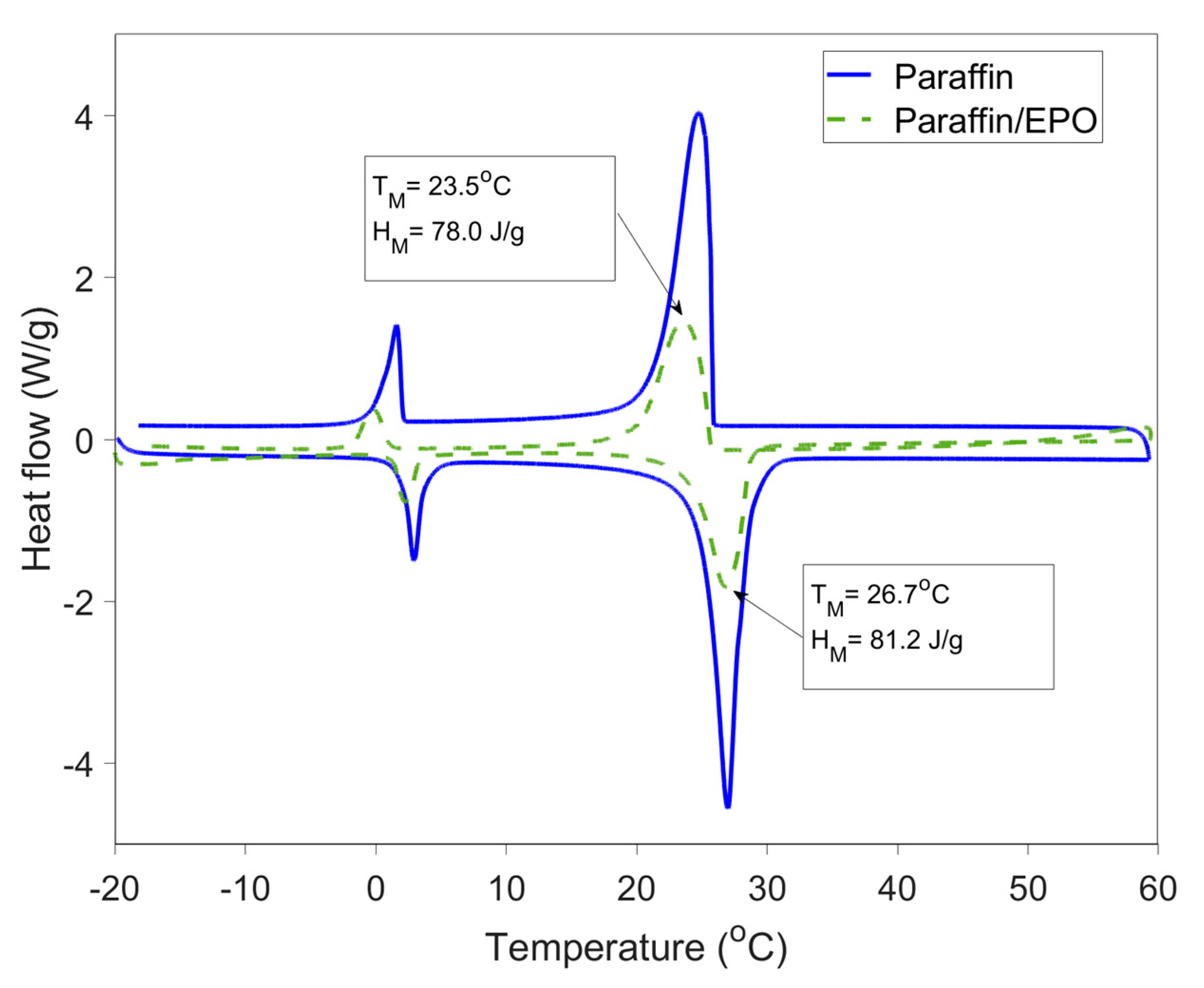
2.1. Materials and Mixing Methods

The FS-PCM was fabricated using paraffin (RT27) with the phase transition temperature of 27 °C and hydrophobic expanded perlite (EPO). The fabrication process of this FS-PCM can be found in the authors’ previous study [24]. The thermo-physical properties of paraffin/EPO FS-PCM, including the peak phase transition temperature and enthalpy, obtained from the differential scanning calorimetry (DSC) test are reported in Figure 1. Here, TM and HM are the peak melting/freezing temperatures and latent heat of fusion for melting/freezing, respectively. From Figure 1, it can be seen that the fabricated FS-PCM has the peak melting and freezing temperature of 26.7 °C and 23.5 °C, respectively. The latent enthalpies of the PCM composite were 81.2 J/g and 78.0 J/g for melting and freezing processes, respectively. The thermo-physical properties of OCB and PCMCB can be found in the authors’ previous study [33].
Ordinary Portland cement (OPC) complying with AS3972 and silica sand (maximum particle size of 1.18 mm) were used for the development of cement mortars. A commercial grade water reducing admixture (WRA, MasterPozzolith 370 from BASF) was used to improve the workability of cement mortars. The gypsum plasterboards used in this study were purchased from Gyprock Pvt Ltd., with the dimensions of 3000 × 1200 × 16 mm and were then cut into smaller pieces at required sizes.
The mix proportion of materials for the development of OCB and PCMCB are given in Table 1. Here, the PCMCB was prepared by replacing 80% by volume of silica sand with FS-PCM. The mixing procedure was as follows. First, cement, sand and PCM composite were dry mixed at low speed for 1 min in a horizontal pan mixer (a Hobart mixer). After the dry materials had been uniformly mixed, water together with admixture was added and mixed for 3 min at low speed. The medium speed mixing was followed for one minute to complete the mixing procedure. Fresh mixes were cast in 300 × 300 × 16 mm3 timber panel moulds and kept in a moist environment for about 24 h. After 24 h, specimens were demoulded and kept in a water bath at 23 ± 0.5 °C for 28 days.

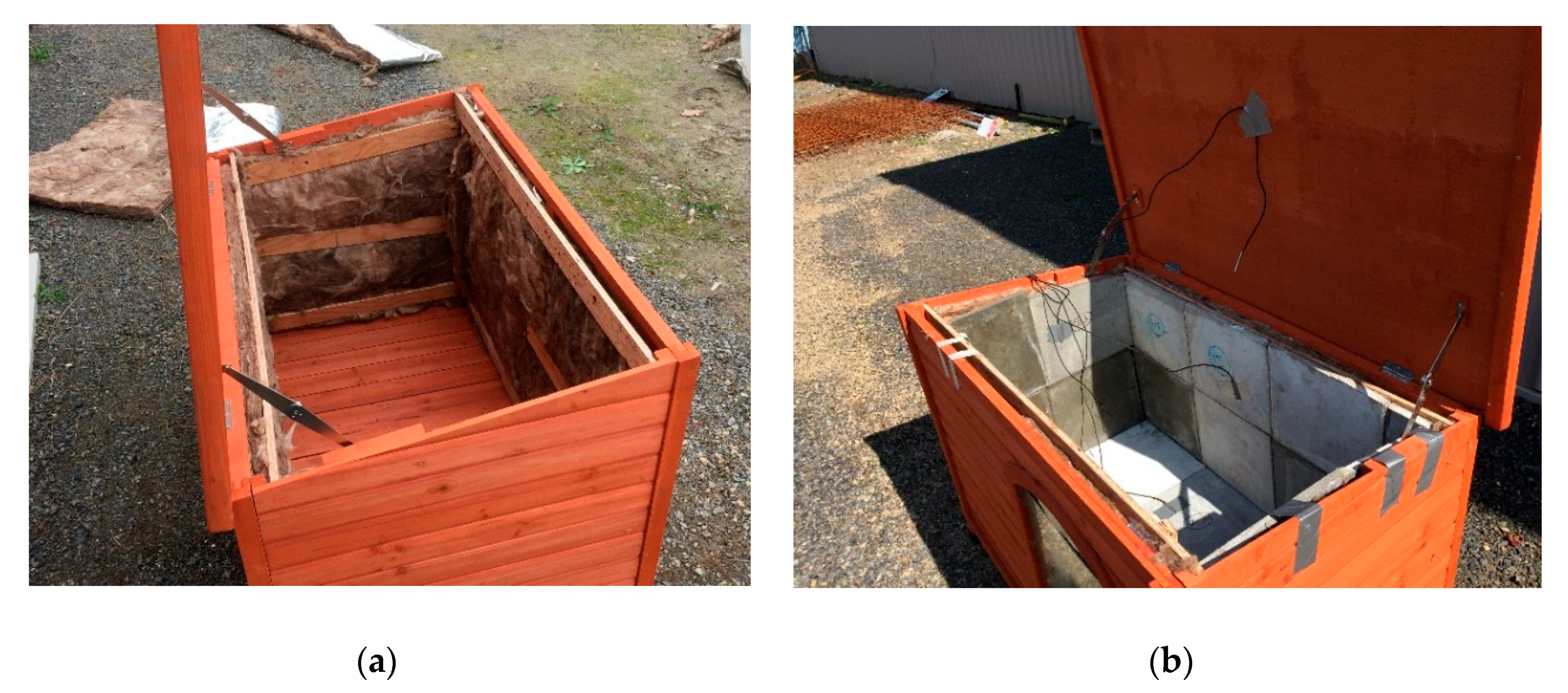
2.2. Description of Modular Test Huts

To assess the thermal performance of PCMCB as the interior surface element in buildings, the test huts must be chosen in a reasonable size, and they should be exposed to outdoor climatic conditions. On this basis, two identically sized test huts were built on a timber-framed structure with an inner volume of 1130 × 725 × 690 mm3. The floor and walls of the test huts were constructed on timber and fully insulated at its interior with 90 mm thick (R 2.0) glass wool insulation. The interior surface of the walls and floor were finished with test panels. A 400 × 400 mm2 double-glazing window was located on the east wall of the test huts through which solar radiation could enter. The window was made of two layers of 4 mm clear glass with an airgap of 10 mm. The roof was made of an R 1.8 insulation layer prefabricated by the manufacturer in between a 2 mm flat iron sheet (outside layer) and 10 mm thick timber panels (inside layer). Figure 2 shows the construction of test huts with the installation of insulation to timber walls followed by the PCMCB test panels as interior wall and floor elements. The detailed construction elements of the test huts are given in Table 2.
The test huts were exposed to the outdoor environment for five months (1 October 2016 to 1 March 2017) and interior and exterior thermal conditions were continuously monitored. While the PCM-incorporated test hut consisted PCMCB as the internal surface element throughout the entire test period (1 October 2016 to 1 March 2017), the control test hut was constructed using GPB for two months (1 October 2016 to 30 November 2016) and OCB for three months (1 December 2016 to 1 March 2017). This was to study the performance enhancement of PCMCB compared to different construction materials of GPB and OCB. The test huts were placed at the Croydon campus of Swinburne University of Technology in Melbourne, Australia, where the window of the test huts was facing east without much shading of trees and neighbouring buildings.

2.3. Measurements

The test huts were equipped with a set of thermocouples, which were connected to a data acquisition system and continuously monitored and recorded the temperature variation during the test period. The thermistors were k-type thermocouples supplied by ICT Instruments and they were connected to an ICT SDI-12 Datalogger system. The temperature measurements were collected at an interval of 3 min. The accuracy of the thermocouples was rated as ± 0.05 °C, according to the specifications of the manufacturer. The temperature sensors were attached at the interior surface of all walls and floor to measure the surface temperatures, as well as at the geometric centre of the test hut to measure the indoor temperature. The outdoor thermal conditions, including the outdoor air temperature and solar radiation, were monitored by a Wireless Vintage Pro 2 weather station from Davis Instruments. The weather station was mounted on a pole at an elevation of approximately 10 m from the ground.

2.4. Analysis Method

The thermal performance enhancement of PCMCB compared to GPB and OCB was studied by comparing the indoor thermal conditions between different test huts during the test period. The reductions in peak and diurnal temperature fluctuations were considered as the indicators for the direct measurement of thermal performance enhancement in the PCMCB test huts. Two additional indicators were chosen to study the overheating effects by considering the reduction in intensity and frequency of thermal discomfort as below. Other external factors influencing the overheating effects include building surroundings, shadings and wind speed. They were assumed to be similar since both test huts were constructed in the same location.
(1)
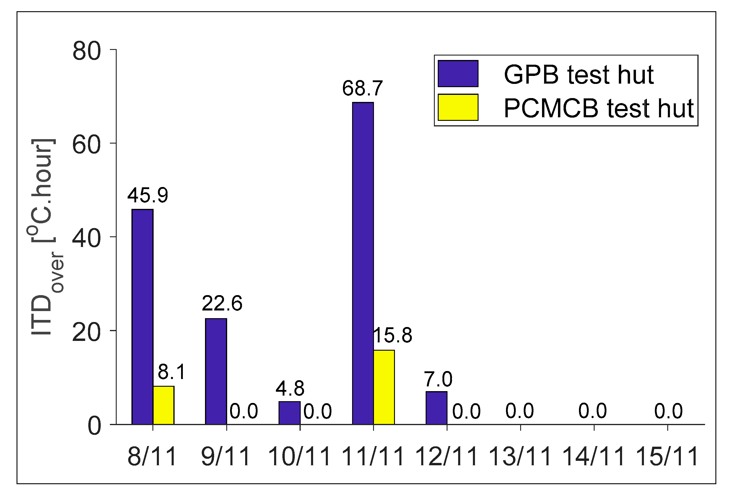
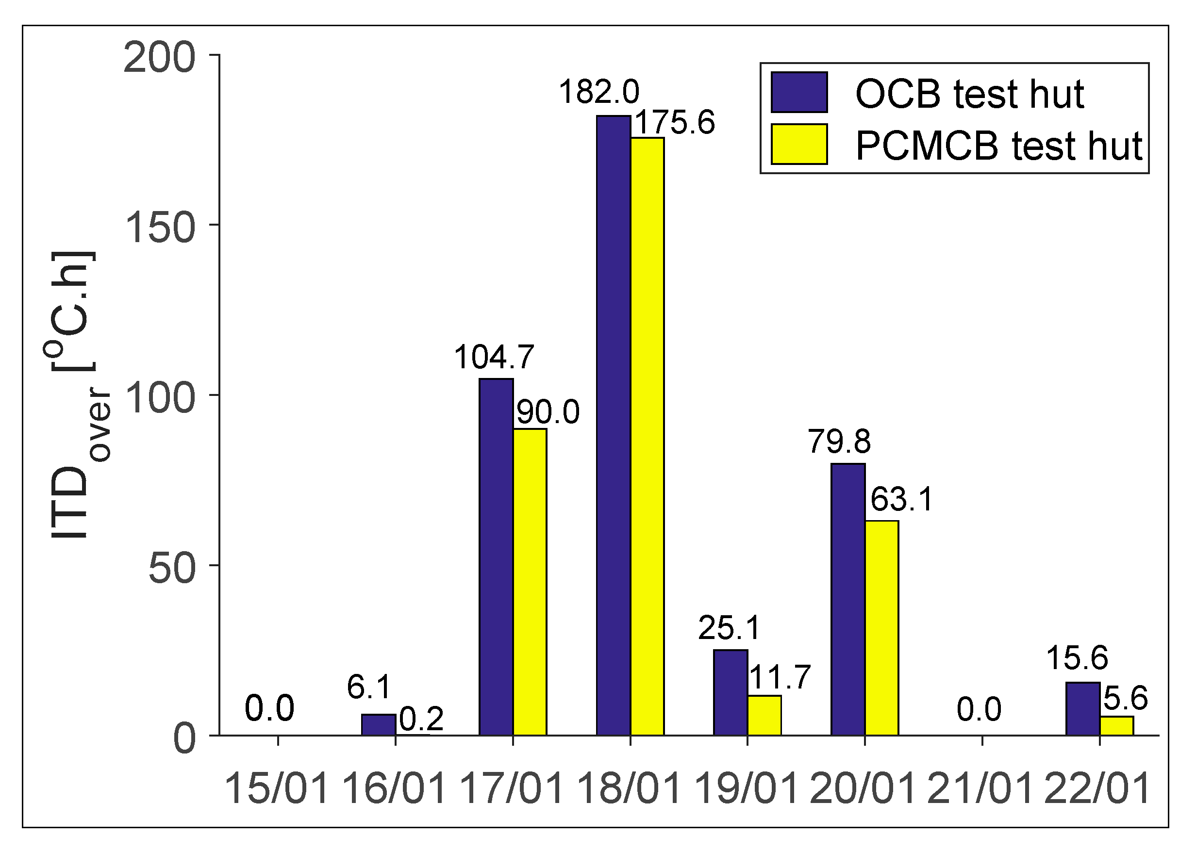
Intensity of thermal discomfort for overheating (ITDover) is defined as the time integral of the positive difference between the indoor operative temperature and the upper threshold for comfort. Here, the upper threshold temperature (Tlim) depends on the thermal comfort theory used to assess the indoor thermal comfort. This study used the adaptive comfort model based on ASHRAE Standard 55-2013 [46] with 80% acceptability limits as shown in Equation (2) to Equation (4). Here, Tope and Tlim refer to indoor operative temperature and upper threshold temperature of thermal comfort, respectively. Tcomf, Tdrybulb, TMRT and Ta,out are optimum comfort temperature, dry-bulb temperature, mean radiant temperature and mean monthly outdoor air temperature, respectively. The radiative fraction γ depends on the air velocity and for air velocity lesser than 0.2 m/s, the typical value of 0.5 will apply as recommended in ISO 77300 [47].
I T D o v e r = d a y 0 Δ T + ( t ) d t where ,   Δ T + ( t ) =   { T o p e ( t ) T l i m i f   T o p e ( t ) > T l i m 0 i f   T o p e ( t ) T l i m
T o p e = γ T M R T + ( 1 γ ) T d r y b u l b  
T c o m f   =   0.31   ×   T a , o u t + 17.8
T l i m = T c o m f + 3.5   ° C
(2)
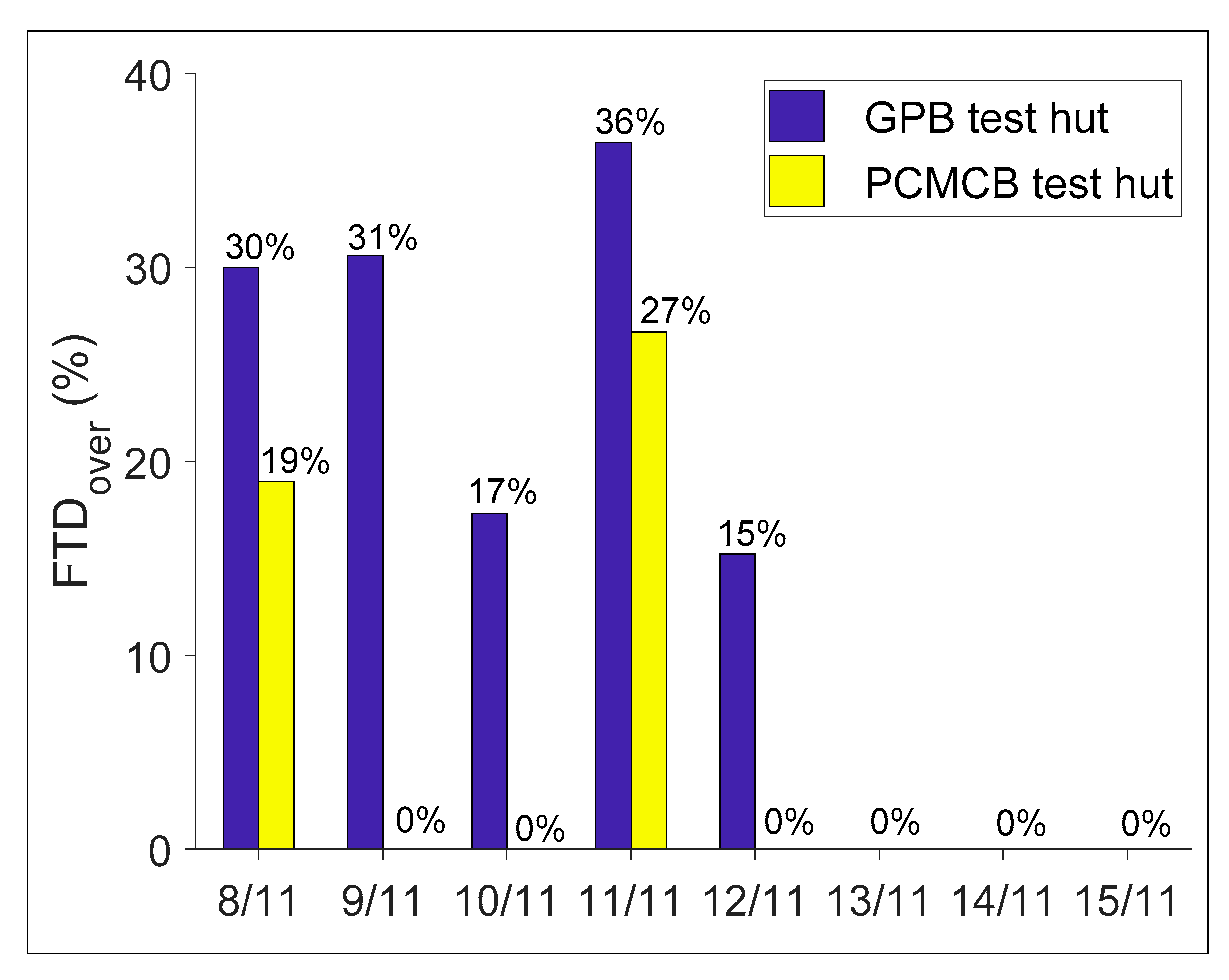
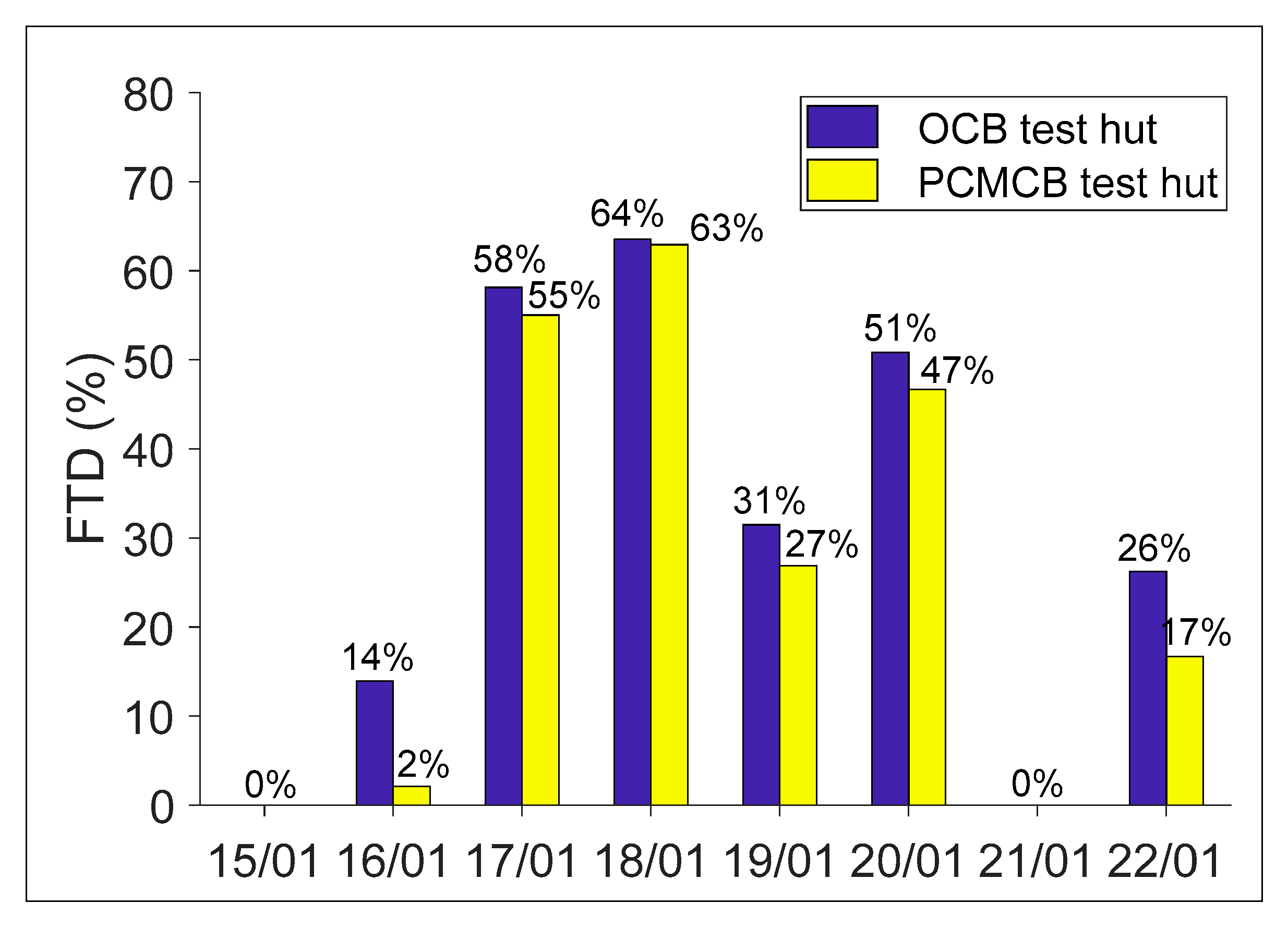
Frequency of thermal discomfort for overheating (FTDover) is defined as the time-period in a day, during which the indoor operative temperature falls above the upper threshold of comfort. Here, tD refers to the cumulative overheated period in a day.
F T D o v e r = t D 24 × 100 %

3. Results and Discussions

3.1. Overview

The temperature monitoring of the test huts for a five-month period resulted in a large amount of data collected that provided the insights of the influence of PCMCB over typical building materials of GPB and OCB. However, reporting such large amounts of data would be difficult. Thus, the comparison of PCMCB with GPB and OCB was analysed and reported for eight consecutive days. It must be noted that, in all cases, the behaviour of PCMCB could be distinguished into three situations based on the melting heat transfer behaviour of PCM (i.e., 25–27 °C) as described below:
  • The PCM was not thermally activated throughout the day, as the outdoor temperature or solar irradiance was insufficient to increase the PCM surface temperature above 25 °C.
  • The PCM was thermally activated during the day and returned to the solid phase during the night, because of high daytime temperature/solar irradiance and low night temperature.
  • The PCM was thermally activated during the day and stayed in the melted phase during the night, because of the sufficient daytime temperature/solar irradiance and high night temperature.
The analysis period was chosen to show some or all of the above-mentioned PCM behaviours, and to compare with GPB and OCB. In this regard, the thermal performance assessment of PCMCB with GPB and OCB was reported for the period 8–15 November 2016, and 14–22 January 2017, respectively.

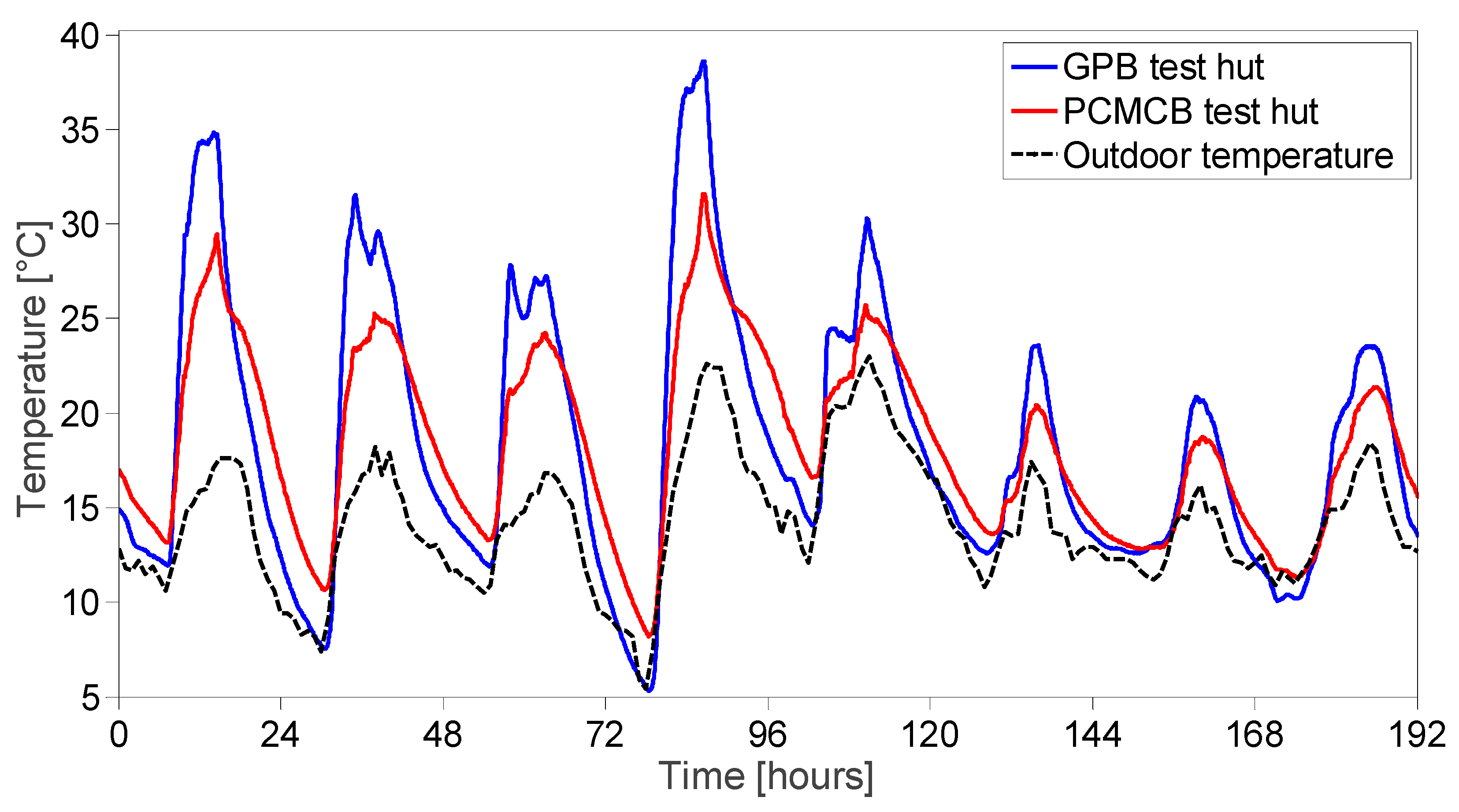
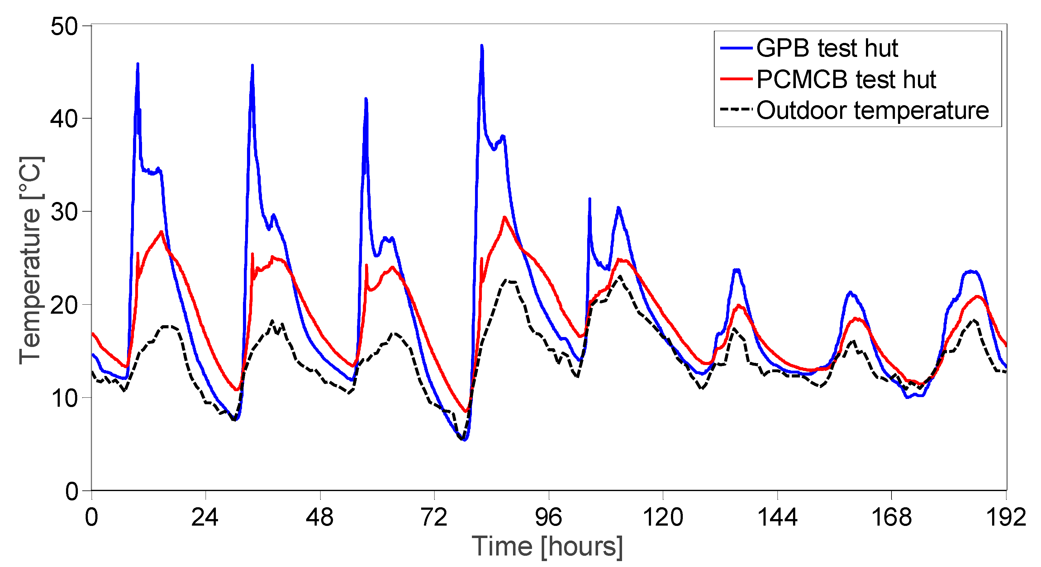
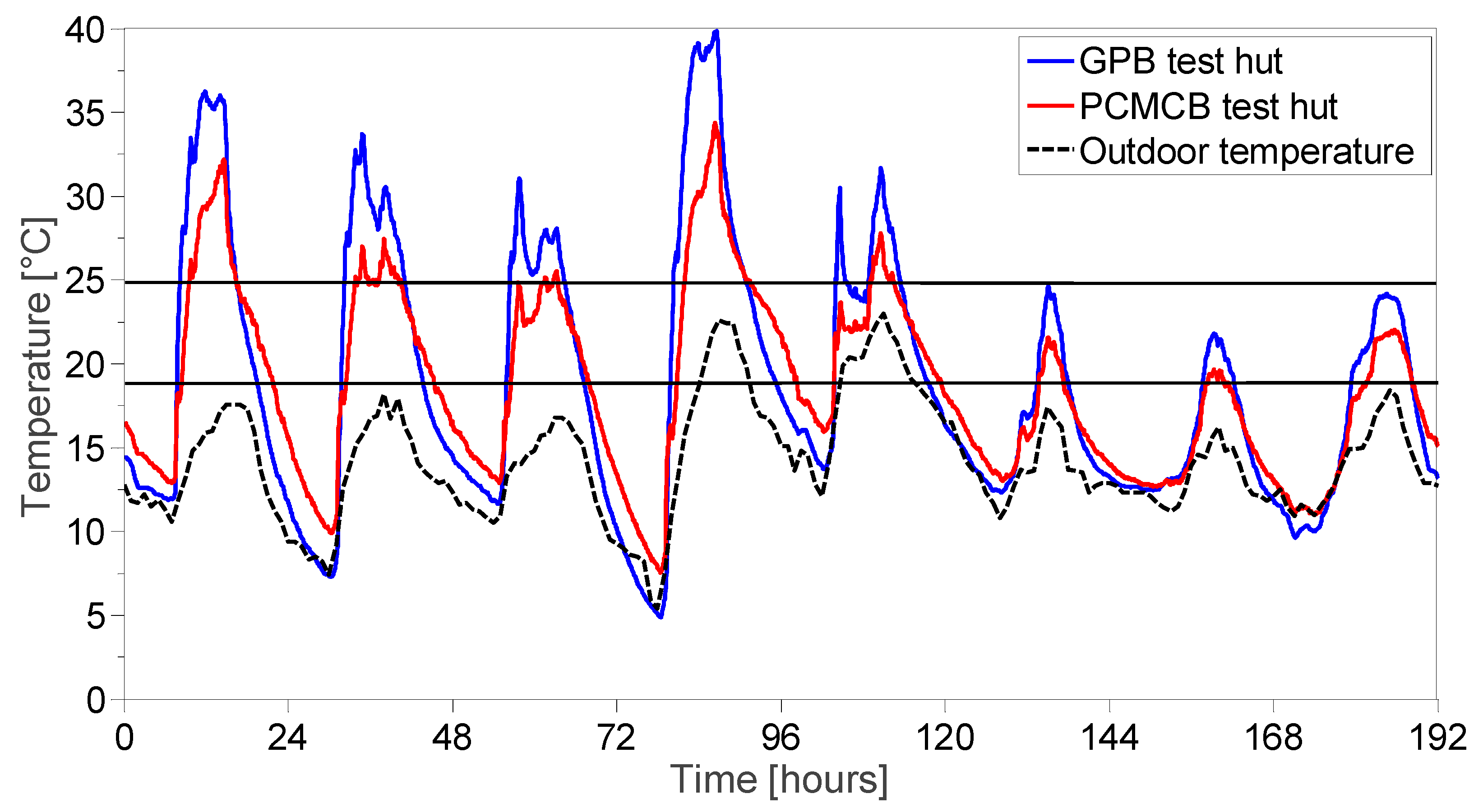
3.2. Thermal Performance Assessment of PCMCB with GPB

During the period 8–15 November 2016, the measured temperatures of the west wall, floor and indoor air for GPB and PCMCB test huts are shown in Figure 3, Figure 4 and Figure 5, respectively. The figures show that throughout the eight consecutive days, the wall and floor surface temperatures, as well as the indoor air temperature in the PCMCB test hut was significantly lower than the GPB test hut. Considering the west wall surface temperature as an example, the peak temperature of the GPB test hut reached well above 30 °C for four days out of eight days. The PCMCB test hut, however, achieved a lower peak temperature during this period. For example, the reduction in peak wall temperatures of 2.1 °C and 2.4 °C was observed on the first and second day, respectively. Figure 3 also reveals that the PCMCB not only reduced the peak surface temperature but also increased the daily minimum temperatures due to the discharge of stored latent heat. This ultimately reduced the diurnal temperature fluctuations indoors, thus improving the indoor thermal comfort. This reveals the potential benefits of replacing the gypsum plasterboards with PCMCB as an energy refurbishment approach. However, it is worth mentioning here that during the eight days, the PCM was completely charged only on the first and fourth day of the test period since the surface temperature exceeded 27 °C. The surface temperature reduction on other days was attributed to partial latent heat storage, high sensible heat storage and high thermal resistance of PCMCB, compared to GPB.
Although a significant reduction in surface temperatures was achieved in the first five days of the test period, the effect of PCM was not evident on the following three days. This was attributed to the first situation of PCM behaviour explained above, where outdoor air temperature or solar irradiance was not sufficient to thermally activate the PCM. Thus, the reduction in peak temperature and diurnal temperature fluctuations were not significant during these days. A minor improvement was evident as high sensible heat capacity and high thermal resistance (low thermal conductivity) of PCMCB assisted in reducing the peak temperatures.
On the other hand, the floor temperature variation, as shown in Figure 4, indicated that the daytime floor temperature of the GPB test hut exceeded 40 °C for short periods (i.e., early morning time) due to direct solar radiation falling on the floor through the window. However, the recorded floor temperature in the PCMCB test hut was limited to the melting temperature range due to the exploitation of latent heat capacity. The comparison of indoor air temperature variation as depicted in Figure 5 shows that the indoor air temperature behaviour was quite similar to the wall surface temperatures within the test huts, due to the fact that the heat balance between surfaces and indoor air can be attained quickly in these test huts. The peak indoor temperature in the PCMCB test hut was found to be significantly lower than the GPB test hut. Moreover, on most of the days, the PCMCB test hut limited the peak indoor temperature below the upper threshold temperature for thermal comfort, thus indicating the indoor thermal comfort conditions were significantly enhanced.
While the comparison of indoor and inner surface temperatures evidenced the improvement in thermal comfort conditions, the potentiality of PCMCB in reducing the overheating should be assessed. In this regard, the proposed indicators of ITDover and FTDover were assessed for the eight consecutive days and the corresponding results are reported in Figure 6 and Figure 7, respectively. From Figure 6, it can be seen that during the warmer days ITDover reaches up to 22.6 °C.h in the GPB test hut; the use of PCMCB completely offset the thermal discomfort due to overheating. On the very warm days of 8 November and 11 November, the PCMCB test hut reduced the ITDover from 45.9 to 8.1 and 68.7 to 15.8, respectively. The corresponding percentage reduction can be determined as 82% and 77%, respectively. This reveals that the replacement of modern lightweight construction material of GPB with the thermally enhanced PCMCB would have great potential in preventing the overheating during summer periods with the potential reduction in ITDover of up to 52.9 °C.h.
On the other hand, the comparison of FTDover in the two test huts showed that during the eight consecutive days, the GPB test hut experienced overheating between 3 to 9 h of the day (15–36% in a day) for five consecutive days. The PCMCB test hut, however, completely eliminated the overheating for three days out of these five days. In the other two days (first and fourth day), the PCMCB test hut reduced the overheated period from 30% to 19% and 36% to 27%, respectively, compared to the GPB test hut. The corresponding percentage reduction can be determined as 38% and 26%, respectively. Here, it was possible to notice that the PCMCB refurbishment in the test huts had a major effect on reducing the intensity of thermal discomfort, whereas its occurrence was still remarkable. Similar observations have been made by Sicurella et al. [39] and Castell et al. [48] for the effect of glazed area and PCM incorporation, respectively, in buildings. While the ITDover explains how far the indoor environment from comfort conditions changes, the FTDover gives a summarised output on whether thermal comfort conditions are met. Therefore, the days with continued periods of highly intensive thermal discomfort had resulted in a significant reduction of ITDover and a lesser reduction of FTDover. These results demonstrate that the PCMCB can be useful in preventing overheating during summer, but improvement in the period of indoor thermal comfort was not significant.

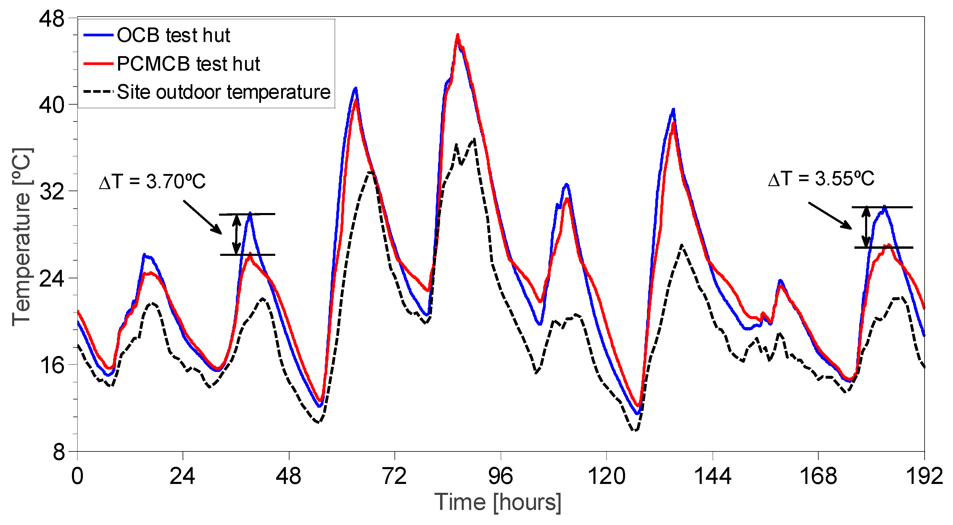
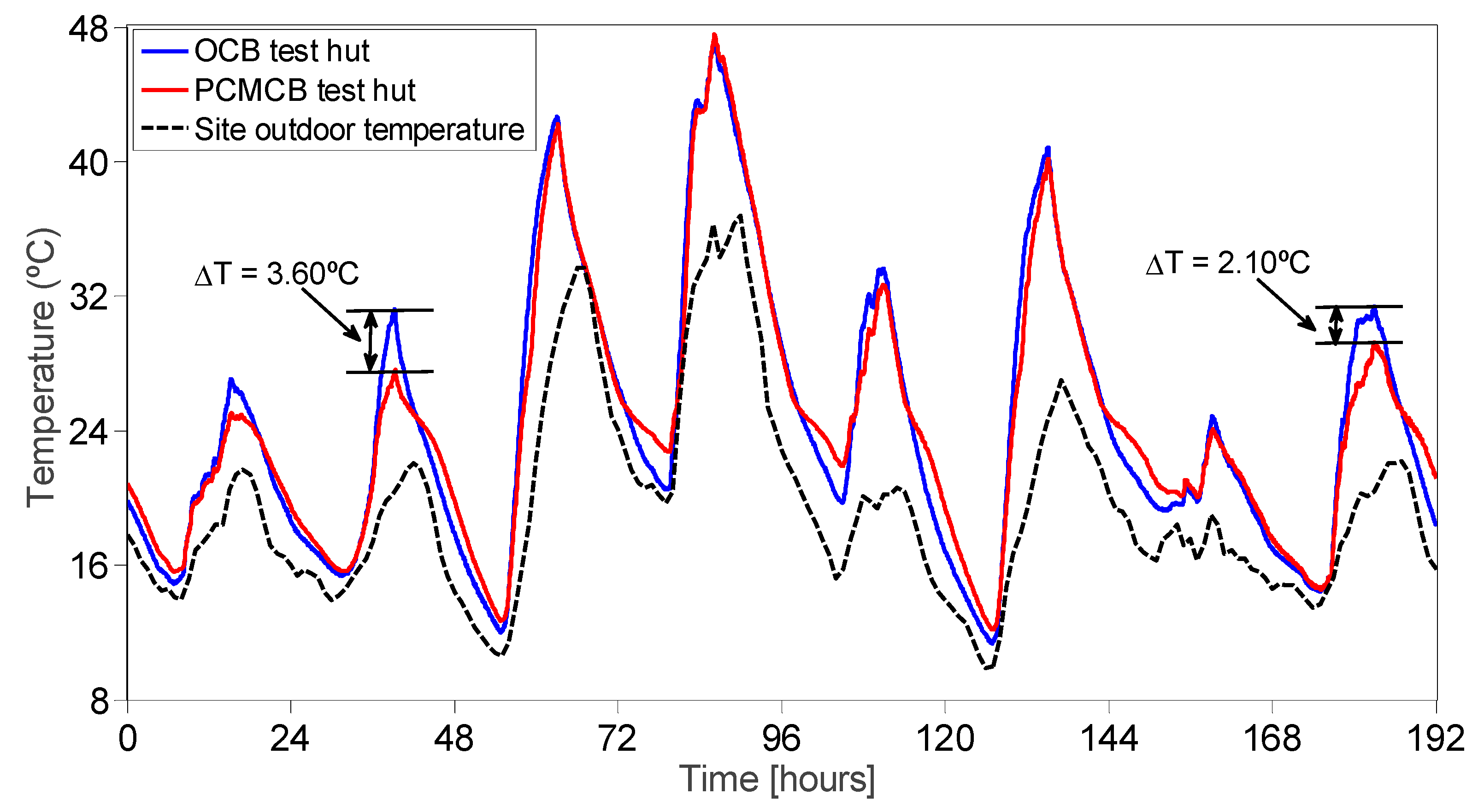
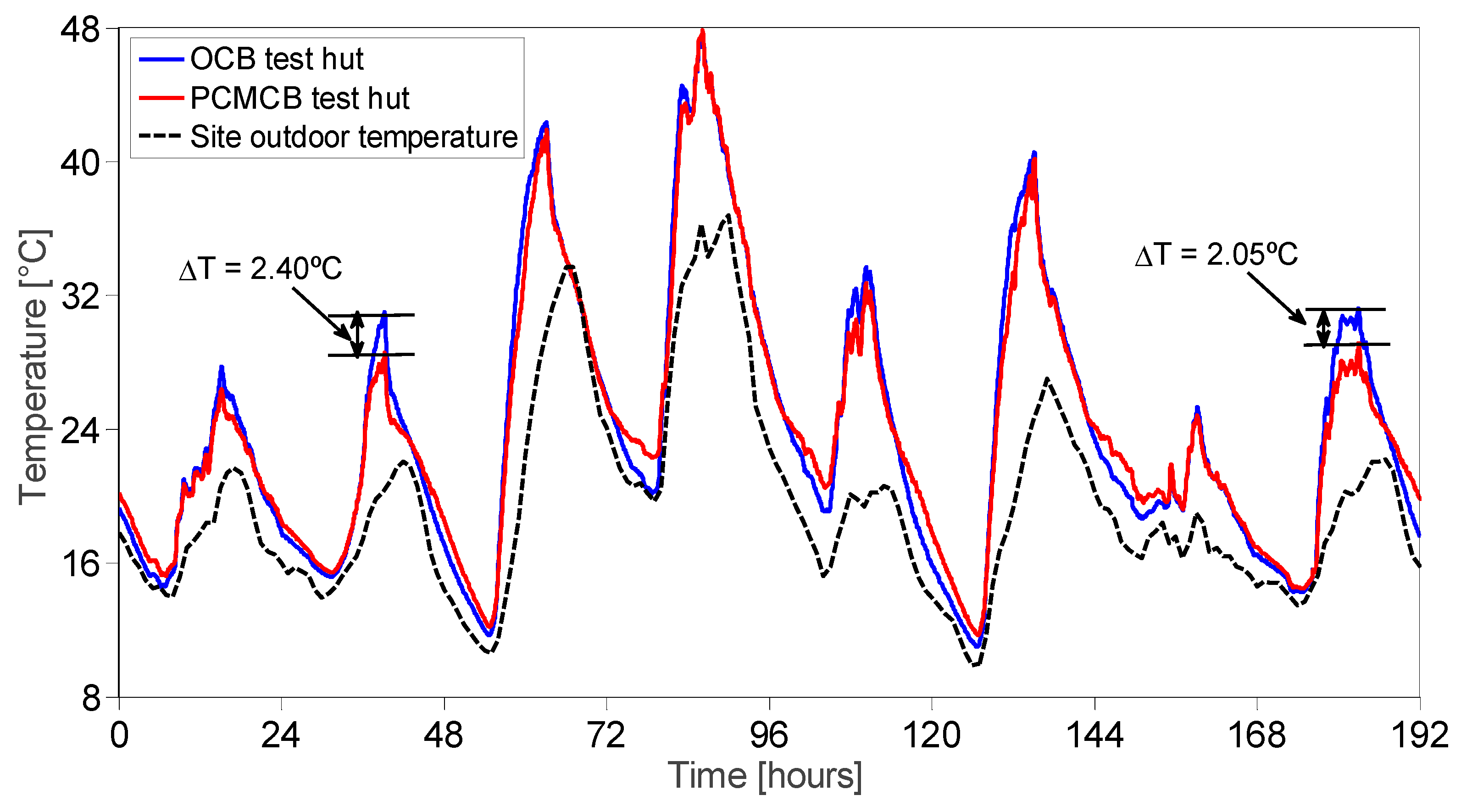
3.3. Thermal Performance Assessment of PCMCB with OCB

In this section, a comparison between the test huts made of OCB and PCMCB were compared. During the period 14–21 January 2017, the measured temperatures of the west wall, floor and indoor air are displayed in Figure 8, Figure 9 and Figure 10, respectively. When comparing the temperature measurements of the west wall and floor surfaces as shown in Figure 8 and Figure 9, respectively, the reduction in peak surface temperature was only significant on the first, second and eighth days. On these days, the maximum surface temperature reached in the OCB test hut was approximately 30 °C, which is adequate to thermally activate the PCM in the PCMCB test hut. Thus, the observed surface temperatures in the PCMCB test hut were significantly lower than the OCB test hut. During the other days, the peak surface temperature measurements were higher than 30 °C, and hence, the PCM was only effective for a short period and becomes ineffective once it is completely melted. Moreover, it was also observed that the minimum surface temperature of the PCMCB test hut was higher than the OCB test hut due to latent heat discharge of PCM. For example, the minimum wall and floor surface temperatures were increased by up to 2.2 ± 0.3 °C during this period.
On the other hand, the inspection of indoor air temperature as illustrated in Figure 10 reveals that the PCM was effective when the maximum indoor temperature reached around 30 °C. As the maximum indoor temperature goes above 30 °C, PCM becomes ineffective in reducing the peak indoor temperature. This is demonstrated by comparing the second and eighth days of the test period with the third and fourth days, where the days with a maximum indoor temperature around 30 °C (second and eighth days) resulted in the reduction of peak indoor temperature by approximately 2.2 °C, compared to just about 0.5 °C on the other days. It can be said, therefore, that PCM incorporation into an interior surface element can be very effective when the maximum indoor temperature exceeds 2–3 °C above PCM melting temperature. Furthermore, significantly higher peak indoor temperatures above PCM operating temperature will result in a rapid melting process and will be completely melted within a shorter period, thus becoming ineffective in reducing the peak indoor temperatures and diurnal temperature fluctuations. In this regard, future studies are required to consider the incorporation of multiple PCMs with different melting points into cementitious materials, so that the particular PCM becomes thermally active when the indoor thermal conditions become favourable to it.
The performance of PCMCB in reducing overheating effects in the test hut, as measured by ITDover and FTDover, is presented in Figure 11 and Figure 12, respectively. As plotted in Figure 11, the reduction in daily ITDover with the replacement of PCMCB for OCB was lower than the reduction against the GPB test hut. For example, on the warmer days of the third and sixth days, the percentage reduction in ITDover of the PCMCB test hut was 14% and 21%, compared to the OCB test hut. This behaviour reflects the high thermal capacity of OCB compared to GPB. On very hot days (e.g., fourth day), the performance enhancement of PCMCB was further reduced with the reduction of just 3.5%. On the other hand, the period of exposure to overheating measured by FTDover is shown in Figure 12. Once again, similar to the observations made in the GPB and PCMCB test huts, the reduction in FTDover with the PCMCB refurbishment was not significant compared to the OCB test hut.
In an attempt to identify the potential reduction of overheating at different levels of overheating (i.e., low, medium and high) intensity and frequency, the reduction in these performance indicators (ΔITDover and ΔFTDover) due to the PCMCB refurbishment against the recorded values for the OCB test hut is given in Table 3. It is interesting to note that the reduction in ITDover followed a trend with the recorded ITDover in the OCB test hut. At low intensity of thermal discomfort in OCB, the reduction due to the PCMCB was also low. When the ITDover increased in the OCB test hut, the reduction amount increased and reached a peak at 79.8 °C.h, and thereafter declined. It can be said, therefore, that the effect of PCMCB in reducing the intensity of thermal discomfort would be low at very low and very high intensity of thermal discomfort. Furthermore, the maximum benefits of PCMCB in reducing the intensity of thermal discomfort can be observed at medium intensity levels. On the other hand, the reduction in the period of exposure to overheating followed a different trend against the period recorded for the OCB test hut. At the short periods of thermal discomfort (i.e., low FTDover in the OCB test hut), the PCMCB test hut showed the highest reduction in the FTDover. As the FTDover increased in the control test hut, the reduction percentage in the PCMCB test hut decreased as reported in Table 3.
As can be seen from Table 3, the maximum beneficial effects of PCMCB in reducing the intensity of thermal discomfort increased with increasing ITDover in the base test hut (measured in the OCB test hut), reaching a maximum and then declining. Moreover, the maximum reduction in ITDover can be observed at medium intensive thermal discomfort levels. On the other hand, comparison of the frequency of thermal discomfort revealed a steadily decreasing trend with increasing FTDover in the base test hut (OCB test hut). Therefore, to put these into perspective, the building refurbishment with PCMCB benefits in reducing the period of thermal discomfort at lower intensive thermal discomfort levels, and at medium intensive discomfort levels, PCMCB benefits in reducing the intensity of thermal discomfort. Both of these are advantages to the occupants as at lower intensive thermal discomfort levels, the occupants suffer from extended periods of exposure to thermal discomfort, and at medium intensive discomfort levels, the intensity of thermal discomfort dominates as the occupants feel thermally uncomfortable even for short periods. In any case, at high intensity and longer periods of thermal discomfort, PCMCB becomes less effective. Future research is required to study the potential ways to reduce highly intensive and longer periods of thermal discomfort in buildings, such as introducing night ventilation indoors.

4. Conclusions

This study presents the thermal performance enhancement of paraffin/hydrophobic expanded perlite FS-PCM (form-stable phase change material) integrated cement boards as a replacement to traditional interior surface elements, such as ordinary cement mortars (OCB) and gypsum plasterboards (GPB). The thermal performance studies were conducted by installing different construction materials as the interior surface element in modular test huts exposed to outdoor thermal conditions. The intensity of thermal discomfort for overheating (ITDover) and frequency of thermal discomfort for overheating (FTDover) were used to assess the performance enhancement of PCMCB with GPB and OCB. Based on the experimental study, the following conclusions can be drawn:
(1)
The comparison of PCMCB and OCB test huts show that the PCMCB could reduce the inner surface and indoor temperatures by up to 3.7 °C and 2.4 °C, respectively. It was also found that the PCMCB is effective in reducing the peak indoor temperatures when the maximum indoor temperatures reach 2–3 °C above PCM operating temperature.
(2)
The evaluation of ITDover and FTDover revealed that the PCMCB significantly reduced the intensity of thermal discomfort for overheating, while showing comparably lower reduction in the periods of thermal discomfort for overheating.
(3)
The comparison of different performance indicators for OCB and PCMCB test huts revealed that at lower intensive thermal discomfort levels, PCMCB assisted in reducing the period of thermal discomfort (FTDover) for overheating. As the intensity of thermal discomfort increased, the reduction in the intensity (ITDover) became dominant. At highly intensive thermal discomfort levels, the reduction was neither apparent in ITDover nor FTDover.
Although the current study demonstrated the comparative analysis of PCM integrated cementitious composites in reducing overheating effects, the considered prototypes were small compared to real buildings. Our future study will assess the performance enhancement of this novel PCM-integrated cementitious composite in real buildings by considering a real compartment or modular houses.

Author Contributions

S.R. conducted the experimental works and prepared the original draft paper. J.S. developed the conceptualization and methodology of research work. X.W. reviewed and edited the draft paper.

Funding

This research was funded by CSIRO Climate Adaptation Flagship for extreme events.

Acknowledgments

The first author acknowledges Swinburne University of Technology and CSIRO Climate Adaptation Flagship for supporting the project through a SUPRA scholarship and top-up scholarship, respectively.

Conflicts of Interest

The authors declare no conflict of interest.

References

  1. EIA, U. International energy outlook 2017. International Energy Outlook, US Engergy Information Adminstration Report September, 2017. Available online: https://www.eia.gov/outlooks/ieo/pdf/0484(2017).pdf (accessed on 11 April 2018).
  2. Pyrgou, A.; Castaldo, V.L.; Pisello, A.L.; Cotana, F.; Santamouris, M. On the effect of summer heatwaves and urban overheating on building thermal-energy performance in central Italy. Sustainable Cities and Soc. 2017, 28, 187–200. [Google Scholar] [CrossRef]
  3. Sage-Lauck, J.S.; Sailor, D.J. Evaluation of phase change materials for improving thermal comfort in a super-insulated residential building. Energy Build. 2014, 79, 32–40. [Google Scholar] [CrossRef]
  4. Soares, N.; Costa, J.J.; Gaspar, A.R.; Santos, P. Review of passive PCM latent heat thermal energy storage systems towards buildings’ energy efficiency. Energy Build. 2013, 59, 82–103. [Google Scholar] [CrossRef]
  5. Zhou, D.; Zhao, C.Y.; Tian, Y. Review on thermal energy storage with phase change materials (PCMs) in building applications. Appl. Energy 2012, 92, 593–605. [Google Scholar] [CrossRef] [Green Version]
  6. Zalba, B.; Marın, J.M.; Cabeza, L.F.; Mehling, H. Review on thermal energy storage with phase change: Materials, heat transfer analysis and applications. Appl. Therm. Eng. 2003, 23, 251–283. [Google Scholar] [CrossRef]
  7. Waqas, A.; Din, Z.U. Phase change material (PCM) storage for free cooling of buildings—A review. Renew. Sustain. Energy Rev. 2013, 18, 607–625. [Google Scholar] [CrossRef]
  8. Cabeza, L.F.; Castell, A.; Barreneche, C.D.; De Gracia, A.; Fernández, A.I. Materials used as PCM in thermal energy storage in buildings: A review. Renew. Sustain. Energy Rev. 2011, 15, 1675–1695. [Google Scholar] [CrossRef]
  9. Regin, A.F.; Solanki, S.C.; Saini, J.S. Heat transfer characteristics of thermal energy storage system using PCM capsules: A review. Renew. Sustain. Energy Rev. 2008, 12, 2438–2458. [Google Scholar] [CrossRef]
  10. Zhou, G.; Yang, Y.; Wang, X.; Cheng, J. Thermal characteristics of shape-stabilized phase change material wallboard with periodical outside temperature waves. Appl. Energy 2010, 87, 2666–2672. [Google Scholar] [CrossRef]
  11. Zhou, D.; Shire, G.S.F.; Tian, Y. Parametric analysis of influencing factors in Phase Change Material Wallboard (PCMW). Appl. Energy 2014, 119, 33–42. [Google Scholar] [CrossRef] [Green Version]
  12. Novais, R.M.; Ascensão, G.; Seabra, M.P.; Labrincha, J.A. Lightweight dense/porous PCM-ceramic tiles for indoor temperature control. Energy Build. 2015, 108, 205–214. [Google Scholar] [CrossRef]
  13. Pisello, A.L.; Fortunati, E.; Mattioli, S.; Cabeza, L.F.; Barreneche, C.; Kenny, J.M.; Cotana, F. Innovative cool roofing membrane with integrated phase change materials: Experimental characterization of morphological, thermal and optic-energy behavior. Energy Build. 2016, 112, 40–48. [Google Scholar] [CrossRef]
  14. Castell, A.; Martorell, I.; Medrano, M.; Pérez, G.; Cabeza, L.F. Experimental study of using PCM in brick constructive solutions for passive cooling. Energy Build. 2010, 42, 534–540. [Google Scholar] [CrossRef]
  15. Hunger, M.; Entrop, A.G.; Mandilaras, I.; Brouwers, H.J.H.; Founti, M. The behavior of self-compacting concrete containing micro-encapsulated Phase Change Materials. Cem. Concr. Compos. 2009, 31, 731–743. [Google Scholar] [CrossRef]
  16. Entrop, A.G.; Brouwers, H.J.H.; Reinders, A.H.M.E. Experimental research on the use of micro-encapsulated Phase Change Materials to store solar energy in concrete floors and to save energy in Dutch houses. Solar Energy 2011, 85, 1007–1020. [Google Scholar] [CrossRef]
  17. Olivieri, L.; Tenorio, J.A.; Revuelta, D.; Navarro, L.; Cabeza, L.F. Developing a PCM-enhanced mortar for thermally active precast walls. Constr. Build. Mater. 2018, 181, 638–649. [Google Scholar] [CrossRef]
  18. D’Alessandro, A.; Pisello, A.L.; Fabiani, C.; Ubertini, F.; Cabeza, L.F.; Cotana, F. Multifunctional smart concretes with novel phase change materials: Mechanical and thermo-energy investigation. Appl. Energy 2018, 212, 1448–1461. [Google Scholar] [CrossRef]
  19. Xu, B.; Li, Z. Paraffin/diatomite composite phase change material incorporated cement-based composite for thermal energy storage. Appl. Energy 2013, 105, 229–237. [Google Scholar] [CrossRef]
  20. Li, X.; Sanjayan, J.G.; Wilson, J.L. Fabrication and stability of form-stable diatomite/paraffin phase change material composites. Energy Build. 2014, 76, 284–294. [Google Scholar] [CrossRef]
  21. Xu, B.; Ma, H.; Lu, Z.; Li, Z. Paraffin/expanded vermiculite composite phase change material as aggregate for developing lightweight thermal energy storage cement-based composites. Appl. Energy 2015, 160, 358–367. [Google Scholar] [CrossRef]
  22. Chung, O.; Jeong, S.-G.; Kim, S. Preparation of energy efficient paraffinic PCMs/expanded vermiculite and perlite composites for energy saving in buildings. Sol. Energy Mater. Sol. Cells 2015, 137, 107–112. [Google Scholar] [CrossRef]
  23. Li, X.; Chen, H.; Liu, L.; Lu, Z.; Sanjayan, J.G.; Duan, W.H. Development of granular expanded perlite/paraffin phase change material composites and prevention of leakage. Solar Energy 2016, 137, 179–188. [Google Scholar] [CrossRef]
  24. Ramakrishnan, S.; Sanjayan, J.; Wang, X.; Alam, M.; Wilson, J. A novel paraffin/expanded perlite composite phase change material for prevention of PCM leakage in cementitious composites. Appl. Energy 2015, 157, 85–94. [Google Scholar] [CrossRef]
  25. Ramakrishnan, S.; Wang, X.; Sanjayan, J.; Wilson, J. Assessing the feasibility of integrating form-stable phase change material composites with cementitious composites and prevention of PCM leakage. Mater. Lett. 2017, 192, 88–91. [Google Scholar] [CrossRef]
  26. Zhang, Z.; Shi, G.; Wang, S.; Fang, X.; Liu, X. Thermal energy storage cement mortar containing n-octadecane/expanded graphite composite phase change material. Renew. Energy 2013, 50, 670–675. [Google Scholar] [CrossRef]
  27. Li, M. A nano-graphite/paraffin phase change material with high thermal conductivity. Appl. Energy 2013, 106, 25–30. [Google Scholar] [CrossRef]
  28. Fang, X.; Zhang, Z. A novel montmorillonite-based composite phase change material and its applications in thermal storage building materials. Energy Build. 2006, 38, 377–380. [Google Scholar] [CrossRef]
  29. Kheradmand, M.; Castro-Gomes, J.; Azenha, M.; Silva, P.D.; de Aguiar, J.L.; Zoorob, S.E. Assessing the feasibility of impregnating phase change materials in lightweight aggregate for development of thermal energy storage systems. Constr. Build. Mater. 2015, 89, 48–59. [Google Scholar] [CrossRef] [Green Version]
  30. Memon, S.A. Phase change materials integrated in building walls: A state of the art review. Renew. Sustain. Energy Rev. 2014, 31, 870–906. [Google Scholar] [CrossRef]
  31. Karaman, S.; Karaipekli, A.; Sarı, A.; Bicer, A. Polyethylene glycol (PEG)/diatomite composite as a novel form-stable phase change material for thermal energy storage. Sol. Energy Mater. Sol. Cells 2011, 95, 1647–1653. [Google Scholar] [CrossRef]
  32. Ruzaidi, C.M.; Al Bakri, A.M.M.; Binhussain, M.; Salwa, M.S.; Alida, A.; Faheem, M.; Azlin, S.S.; Muhammad Faheem, M.T. Study on properties and morphology of kaolin based geopolymer coating on clay substrates. Key Eng. Mater. 2014, 594, 540–545. [Google Scholar] [CrossRef]
  33. Ramakrishnan, S.; Wang, X.; Sanjayan, J.; Wilson, J. Thermal performance assessment of phase change material integrated cementitious composites in buildings: Experimental and numerical approach. Appl. Energy 2017, 207, 654–664. [Google Scholar] [CrossRef]
  34. Ramakrishnan, S.; Wang, X.; Sanjayan, J.; Wilson, J. Thermal energy storage enhancement of lightweight cement mortars with the application of phase change materials. Procedia Eng. 2017, 180, 1170–1177. [Google Scholar] [CrossRef]
  35. Ramakrishnan, S.; Wang, X.; Sanjayan, J.; Wilson, J. Experimental and Numerical Study on Energy Performance of Buildings Integrated with Phase Change Materials. Energy Procedia 2017, 105, 2214–2219. [Google Scholar] [CrossRef]
  36. Cui, H.; Memon, S.A.; Liu, R. Development, mechanical properties and numerical simulation of macro encapsulated thermal energy storage concrete. Energy Build. 2015, 96, 162–174. [Google Scholar] [CrossRef]
  37. Memon, S.A.; Cui, H.Z.; Zhang, H.; Xing, F. Utilization of macro encapsulated phase change materials for the development of thermal energy storage and structural lightweight aggregate concrete. Appl. Energy 2015, 139, 43–55. [Google Scholar] [CrossRef]
  38. Pisello, A.L.; Goretti, M.; Cotana, F. A method for assessing buildings’ energy efficiency by dynamic simulation and experimental activity. Appl. Energy 2012, 97, 419–429. [Google Scholar] [CrossRef]
  39. Sicurella, F.; Evola, G.; Wurtz, E. A statistical approach for the evaluation of thermal and visual comfort in free-running buildings. Energy Build. 2012, 47, 402–410. [Google Scholar] [CrossRef]
  40. Evola, G.; Marletta, L.; Sicurella, F. A methodology for investigating the effectiveness of PCM wallboards for summer thermal comfort in buildings. Build. Environ. 2013, 59, 517–527. [Google Scholar] [CrossRef]
  41. Jiang, F.; Wang, X.; Zhang, Y. A new method to estimate optimal phase change material characteristics in a passive solar room. Energy Convers. Manage. 2011, 52, 2437–2441. [Google Scholar] [CrossRef]
  42. Mazzeo, D.; Oliveti, G.; Arcuri, N. Definition of a new set of parameters for the dynamic thermal characterization of PCM layers in the presence of one or more liquid-solid interfaces. Energy Build. 2017, 141, 379–396. [Google Scholar] [CrossRef]
  43. Ye, H.; Long, L.; Zhang, H.; Zou, R. The performance evaluation of shape-stabilized phase change materials in building applications using energy saving index. Appl. Energy 2014, 113, 1118–1126. [Google Scholar] [CrossRef]
  44. Mazzeo, D.; Oliveti, G.; Arcuri, N. A Method for Thermal Dimensioning and for Energy Behavior Evaluation of a Building Envelope PCM Layer by Using the Characteristic Days. Energies 2017, 10, 659. [Google Scholar] [CrossRef]
  45. Ramakrishnan, S.; Wang, X.; Sanjayan, J.; Petinakis, E.; Wilson, J. Development of thermal energy storage cementitious composites (TESC) containing a novel paraffin/hydrophobic expanded perlite composite phase change material. Solar Energy 2017, 158, 626–635. [Google Scholar] [CrossRef]
  46. ASHRAE, A. Standard 55-2013: Thermal Environmental Conditions for Human Occupancy; ASHRAE: Atlanta, GA, USA, 2013. [Google Scholar]
  47. Niu, J.; Burnett, J. Integrating radiant/operative temperature controls into building energy simulations. Transactions 1998, 104, 210. [Google Scholar]
  48. Castell, A.; Farid, M.M. Experimental validation of a methodology to assess PCM effectiveness in cooling building envelopes passively. Energy Build. 2014, 81, 59–71. [Google Scholar] [CrossRef]
Figure 1. Thermal properties of paraffin and form-stable phase change material (PCM) [25]. EPO: expanded perlite.
Buildings 09 00057 g001
Figure 2. Test hut set up: (a) installation of insulation to the interior walls; (b) PCMCB installed on the interior surfaces.
Buildings 09 00057 g002
Figure 3. West wall surface temperature in gypsum plasterboard (GPB) and PCMCB test huts (8–15 November 2016).
Buildings 09 00057 g003
Figure 4. Floor surface temperature in GPB and PCMCB test huts (8–15 November 2016).
Buildings 09 00057 g004
Figure 5. Indoor air temperature in GPB and PCMCB test huts (8–15 November 2016).
Buildings 09 00057 g005
Figure 6. Comparison of intensity of thermal discomfort for overheating (ITDover) for GPB and PCMCB.
Buildings 09 00057 g006
Figure 7. Comparison of frequency of thermal discomfort for overheating (FTDover) for GPB and PCMCB.
Buildings 09 00057 g007
Figure 8. West wall surface temperature variations in the OCB and PCMCB test huts.
Buildings 09 00057 g008
Figure 9. Floor surface temperature variations in the OCB and PCMCB test huts.
Buildings 09 00057 g009
Figure 10. Indoor air temperature variations in the OCB and PCMCB test huts.
Buildings 09 00057 g010
Figure 11. Comparison of ITDover in OCB and PCMCB test huts.
Buildings 09 00057 g011
Figure 12. Comparison of FTDover in OCB and PCMCB test huts.
Buildings 09 00057 g012
Table 1. Mix proportion of materials [45]. WRA: water reducing admixture; OCB: ordinary cement mortar; PCMCB: PCM-integrated cement mortar.
Mix DesignationCement
(kg/m3)
Water
(kg/m3)
Silica Sand
(kg/m3)
PCM Composite
(kg/m3)
WRA
(kg/m3)
OCB525255144500
PCMCB52525528924413.1
Table 2. Construction materials/elements of test huts.
SurfaceConstruction Materials (Outside to Inside)
External walls12 mm timber, 90 mm thick (R 2.0) insulation with reflective foil on one side, test panels
Roof2 mm flat iron sheet, R 1.8 insulation, 10 mm thick timber
Floor10 mm timber, 90 mm thick (R 2.0) insulation with reflective foil on one side, test panels
WindowDouble glazing window
Table 3. The reduction of ITDover and FTDover in the PCMCB test hut.
ITDover in OCB test hutITDover in PCMCB test hutΔITDover (PCMCB-OCB)FTDover in OCB test hutFTDover in PCMCB test hutΔFTDover (PCMCB-OCB)
0.00.00.00%0%0%
0.00.00.00%0%0%
6.10.26.014%2%12%
15.65.610.026%17%10%
25.111.713.431%27%5%
79.863.116.751%47%4%
104.790.014.758%55%3%
182.0175.66.464%63%1%

