Article

Adhesion Analysis of Adhesive Mortar Joints in Ceramic Tiles under Static Loading

by
Janaina Salustio da Silva
1,2,
Sandro M. Torres
3,
Ângelo J. Costa e Silva
4,
Fernando A. N. Silva
4,
António C. Azevedo
5 and
João M. P. Q. Delgado
6,*
1
Engineering Department, Federal Rural University of the Semi-Arid (UFERSA), Angicos 59515-000, RN, Brazil
2
Technology Center-Postgraduate Program in Civil and Environmental Engineering, Federal University of Paraíba (UFPB), João Pessoa 58051-900, PB, Brazil
3
Departament of Mechanical Engineering, Federal University of Paraíba (UFPB), João Pessoa 58051-900, PB, Brazil
4
Civil Engineering Department, Pernambuco Catholic University, Recife 50050-900, PE, Brazil
5
Instituto Federal de Ciências de Educação e Tecnologia de Pernambuco (IFPE), Recife 50670-430, PE, Brazil
6
CONSTRUCT-LFC, Department of Civil Engineering, Faculty of Engineering, University of Porto, 4200-465 Porto, Portugal
*
Author to whom correspondence should be addressed.
Buildings 2024, 14(3), 670; https://doi.org/10.3390/buildings14030670
Submission received: 24 January 2024 / Revised: 27 February 2024 / Accepted: 29 February 2024 / Published: 2 March 2024
(This article belongs to the Topic Sustainable and Smart Building)

Abstract

:
Ceramic detachment is a serious problem that persists in modern building constructions despite technological advances and updated regulatory documents. Most of these detachments occur at the interface between the adhesive mortar and the ceramic tile, due to the action of simultaneous tensile and shearing efforts. However, despite this understanding, experimental studies that evaluate the integrity of the adhesion of façades covering materials subjected to simultaneous stress are scarce. In this sense, this study proposes to evaluate the integrity of adhesive mortar joints using the mixed-mode flexure (MMF) crack propagation test. Force and elastic and dissipated energy data were used in this analysis. Prismatic specimens, with a size of 160 × 40 mm2 and a thickness of 6 mm, were produced consisting of two ceramic plates joined by a layer of adhesive mortar at 5 ± 0.5 mm. An acetate film was inserted into one of the mortar–ceramic interfaces in order to simulate the presence of a previous crack, and different crack sizes were used. The results showed the high stress-concentrating effect that the existence of flaws in the interface region has on fracture resistance, as well as the importance of effective contact between the materials. The energy parameters confirmed the analyses carried out based on the load values. The elastic energy of the system fell in the cracked samples, showing that there is a close relationship between the interface energy and the adhesive strength of the material. An energy release of the order of 0.053 ± 0.031 J was required for a 15 mm crack to propagate, creating a fracture surface.

1. Introduction

In Brazil, ceramic coating is one of the main alternatives for protecting building facades, especially in its coastal region. This is especially due to its many advantages, such as durability, impermeability, thermal and acoustic comfort, aesthetic enhancement, and real estate profitability [1]. Ceramic facade cladding is made up of multiple layers, all of which are made on a base that can be made of masonry or concrete. The layers that make it up are the preparation layer, plaster, fixing layer (usually adhesive mortar), and ceramic tiles. In order to achieve the effect shown in [1], all layers must behave in a monolithic manner, minimizing the risks of pathologies that could compromise the coating system.
However, despite technological advances and updated regulatory documents, problems of ceramic detachment are still persistent. In a survey carried out by [2] on pathological manifestations in coverings with ceramic tiles, it was shown that in 84% of the buildings analysed there was the occurrence of detachment with rupture at the ceramic tile/adhesive mortar interface. According to [3], thermal variations occurring in the materials generate tensile and compressive stresses in the ceramic coating. The emergence of traction between layers of different materials also gives rise to shear stresses between the back of the pieces and the adhesive mortar, resulting in warping of the ceramic tile or swelling due to the gradual loss of resistance. According to [1], the greatest difference in modulus of elasticity occurs between adhesive mortars and ceramic tiles; therefore, this interface can be considered the most critical in a ceramic coating system.
The combined action of the forces acting on a facade coating leads to the formation of small defects at the interface of the adhesive mortar with the ceramic tile. Furthermore, other small pre-existing defects, arising from bonding failures, may also be present and propagate through these efforts. According to [4], crack propagation tests would therefore be the most suitable for evaluating the quality of adhesive joints. This is because in the study of fracture mechanics, the focus on the formation and propagation of cracks is essentially important. In these tests, a crack is previously inserted between two glued plates and propagates when a bending load is applied. The mixed-mode flexure (MMF) is the test that uses a combination of pure propagation modes (traction and shear), which is the closest to the action of forces acting on a facade coating.
In [1], the adhesion resistance of the adhesive mortar was evaluated using the MMF test. The research aimed to compare the results of the MMF test with those obtained by the Brazilian test of NBR 14081-4 [5], which only takes into account the traction effort. In this research, the samples presented a region of absence of bonding to represent a defect region in the part. The authors concluded that the resistance values obtained with the Brazilian test are much higher than those achieved by the MMF since the latter takes into account the combined action of efforts.
In [6], the ENF (shear) propagation test was carried out to evaluate the quality of an epoxy resin joint used in the manufacture of parts in the aeronautics sector. The analysis of the quality of the material was carried out based on the assessment of its fracture toughness, where lower toughness values indicated lower adhesion capacity.
Other studies to evaluate the quality of adhesive joints in joining metallic structures in the marine, automotive, and aerospace industries were also carried out under mode I [7,8], mode II [9,10], and mixed-mode [11] loading conditions. These studies investigated the influence of joint thickness on its fracture toughness. In [12], the performance quality of adhesive joints in marine structures was evaluated through their load values, energy release rate, and monitoring of crack growth through digital image correlations.
According to [13], when working with the energetic principles of the material, the analysis of the material’s performance no longer has a local character and starts to have a global character, as it arises from the analysis of the flexibility variation in the solid as a whole (before and after crack propagation). For [14], the failure of engineering materials is evaluated using criteria that are differentiated according to the parameter used, which may be load, tension, deformation, or energy.
Given the above, it appears that although there is a need to better understand the adhesion resistance of mortar joints in coatings and their behavior in the presence of damage, as experimental studies using this type of approach are practically non-existent. In this sense, the present work aims to contribute to the area, evaluating the adhesion resistance of adhesive mortar joints on a ceramic substrate, based on the MMF test, using, as guiding parameters, the maximum load supported and the elastic and dissipated energies of the bonded system.

2. Materials and Methods

To carry out this research, prismatic samples of 40 mm in width, 160 mm in length, and thickness of 17 mm were made, consisting of two ceramic plates (6 mm thick each) joined together using a layer of adhesive mortar. To simulate the presence of a previous crack, an acetate film was inserted into one of the mortar–ceramic interfaces, as shown in Figure 1.
In the production of the samples, a ceramic substrate was used, and in order to guarantee the same contact conditions in all samples, all traces of glue were removed from the back of the ceramics. The ceramic pieces were then washed with detergent and water and then dried in an oven for 24 h, before producing the samples for testing. The physical properties of ceramic slabs are summarized in Table 1; these experimental results were obtained by carrying out the procedures described by NBR 10545-3 [15].
The results presented in Table 1 show that the ceramic material has a reduced absorption rate, being classified according to [16], in group BIb (group of dry-pressed ceramic plates with absorption rates between 0.5% and 3%). This type of material meets the regulatory specifications for use on building façades.
To evaluate the quality of the adhesive joint and better understand the sensitivity of the method and the energy parameters used in this investigation, two types of adhesive mortars were adopted (types A and B). The mortars came from the same manufacturer, differentiated by their adhesiveness. The joint thickness was maintained at 5 ± 0.5 mm. This is a recommended thickness for the standardized test in [17] and is close to the thickness investigated in [1], being the one that favored better mechanical performance for the bonded system.
The mortar samples were produced using a water/mortar dry ratio of 0.2, as recommended by the manufacturer. The tests to characterize the mortars were carried out under laboratory conditions, as specified in [5,17,18,19,20], and the results are presented in Table 2 and Table 3.
According to [17], the mortar characterization results classify mortars A and B as AMI and AMII (according to the evaluation and acceptance criteria presented in Table 2 and Table 3), the latter differing from the manufacturer’s technical specification, which had its classification as AMIII. Working with an AMIII was more desirable since it would make the difference in mechanical performance more significant between the samples and there was no previous work with this type of material, which adopted the energy criterion as a performance evaluation.
The polyvinyl chloride-based acetate film, used to simulate the crack, was 30 µm thick and was implanted at the adhesive/ceramic mortar interface. The acetate film has not received any type of surface treatment. The previous crack was necessary to act as a stress concentrator, producing a preferential fracture plane that represented the preferred type of rupture in facade coatings (adhesive rupture). The choice for this type of film was due to its polymeric composition avoiding problems with folds at the cut end, facilitating implantation in the sample, in addition to being easily purchased on the market.
The crack sizes adopted in implementing the experimental program were: 15 mm, 30 mm, and 45 mm. To minimize thickness variations over the 40 mm width of the test piece, it was decided to cut the film to the same width as the samples.
Once ready, the samples were cured in air, in a laboratory environment with a controlled temperature of 22 °C. Upon reaching the ages of 7, 14, and 28 days, the samples were subjected to the MMF tests, to investigate possible changes in performance as a function of curing time, as illustrated in Figure 2. The equipment used was the Shimadzu universal testing machine Servopulser, with a load application speed of 0.5 mm/min and a load cell with a maximum capacity of 10 kN.
For each study group that included a type of adhesive mortar, a curing time, and a crack size, 3 samples were produced, totalling 72 samples. The nomenclature adopted to identify the samples follows the standard: type of adhesive mortar, size of the previous crack, and curing time.
The adhesion strength of mortar joints was investigated based on material fracture data. The data extracted from the test could provide information for analysis of the following parameters: maximum load, elastic potential energy, and energy released by the bonded system. Furthermore, an analysis of the curve profile at each phase of the process was carried out.

3. Results and Discussion

3.1. Analysis of Adhesion Using the Loading Criterion

To better understand the results, a standard curve will be used as a model to illustrate the loading phases (see Figure 3):
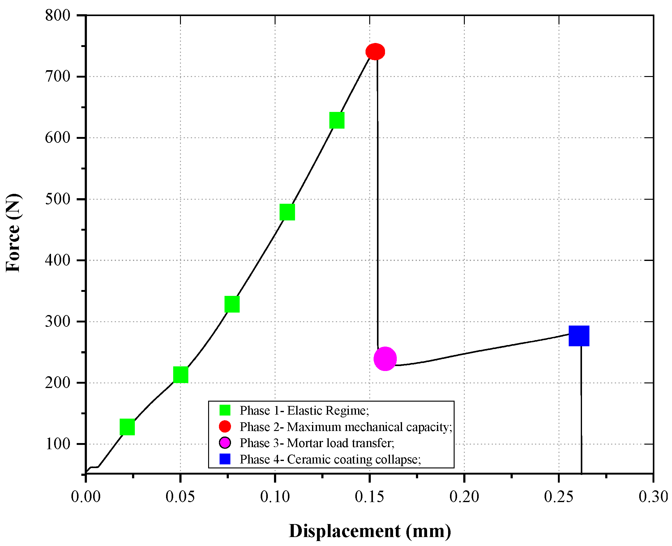
  • Phase 1 presents an increase in the applied force necessary to cause the sample to move. The curve approaches a straight line, i.e., represents the elastic regime of the glued system. During this phase, there is an increase in the stiffness of the sample, which is especially dominated by the stiffness of the mortar.
  • In phase 2, the bonded system reaches its maximum limit of resistance to simultaneous efforts, and from then on there is a loss of resistance, demonstrated by the downhill section between phases 2 and 3.
  • Phase 3 is the point where the load capacity of the mortar is transferred to the ceramic plate, and from then on, the sample’s rigidity is stabilized through the mechanical support of the ceramic plate.
  • Phase 4 marks the end of the test due to the collapse of the ceramic.
Figure 3. The schematization of the MMF curve of the sandwich samples.
Buildings 14 00670 g003
Should be mentioned that a similar behaviour to the propagation curves of this research was reported by [21,22]. The authors also identified the region of influence of the adhesive and the adherent, as well as the region of crack propagation, providing compatibility with what was presented here.
Figure 4 shows a comparison of the curves of the crack-free sandwich samples with a curve obtained from testing three samples of ceramic tiles with dry joints. The results presented in Figure 4 show that the curve of the ceramic plates coincides with the lower part of the curve of the sandwich samples, that is, the section between phase 3 and the end of phase 4. This fact confirms, firstly, that phase 1 of the sandwich samples is dominated by the behaviour of the adhesive, and, therefore, the resistance offered by the material in this section comes predominantly from the stiffness of the adhesive mortar; secondly, that the section of the curve between phases 2 and 3 marks the rupture of the connection between the mortar and the ceramic tile due to the propagation of the crack; thirdly, that from point 3 the mechanical capacity of the sample is markedly dominated by the ceramic, with the transfer of load capacity from the mortar to the slab occurring at this point; and finally, that in point 4 the collapse that occurred is related to the rupture of the plate.
Based on this understanding of the analysis of curve profiles, the results obtained from the MMF test will be presented and discussed. For a better understanding of the experimental data, only one curve from each study group was chosen for presentation in Figure 5, Figure 6, Figure 7, Figure 8, Figure 9, Figure 10, Figure 11 and Figure 12. However, in the discussion of the experimental results obtained, all samples are considered by evaluating the effects of variables (crack size, healing time, and type of mortar) in statistical tests. Furthermore, the average maximum strength values of the samples and their respective standard deviations are presented in Table 4.

3.1.1. Effect of Crack Size

Figure 5 and Figure 6 show the results of the crack propagation test as a function of crack size, for AMI and AMII mortars. An analysis of the curves reveals that the highest values of maximum load are from samples without the presence of a previous crack and that the presence of the crack caused the maximum force resisted by the material (Phase 2) to drop abruptly, starting at a size of 15 mm.
It is also possible to observe that the section of the curve between phases 2 and 3 presented a shorter length as the size of the crack previously inserted in the samples increased. This reduction in the length of the section considered reflects the rapid transfer of load from the mortar to the ceramic tile due to the rapid propagation of the crack that occurred in the adhesive material.
On the other hand, the region of the curve between phases 3 and 4 becomes larger as the extent of the previous crack increases; this means that the greater the extent of the damage, the faster the loss of adhesion of the assembly occurs, with the support mechanical maintained by the resistance of the ceramic plate. Furthermore, since this final support comes predominantly from ceramics, the rupture that occurs in phase 4 always occurs at the same level of displacement supported by the sample, regardless of the level of cracking of the adhesive mortar.
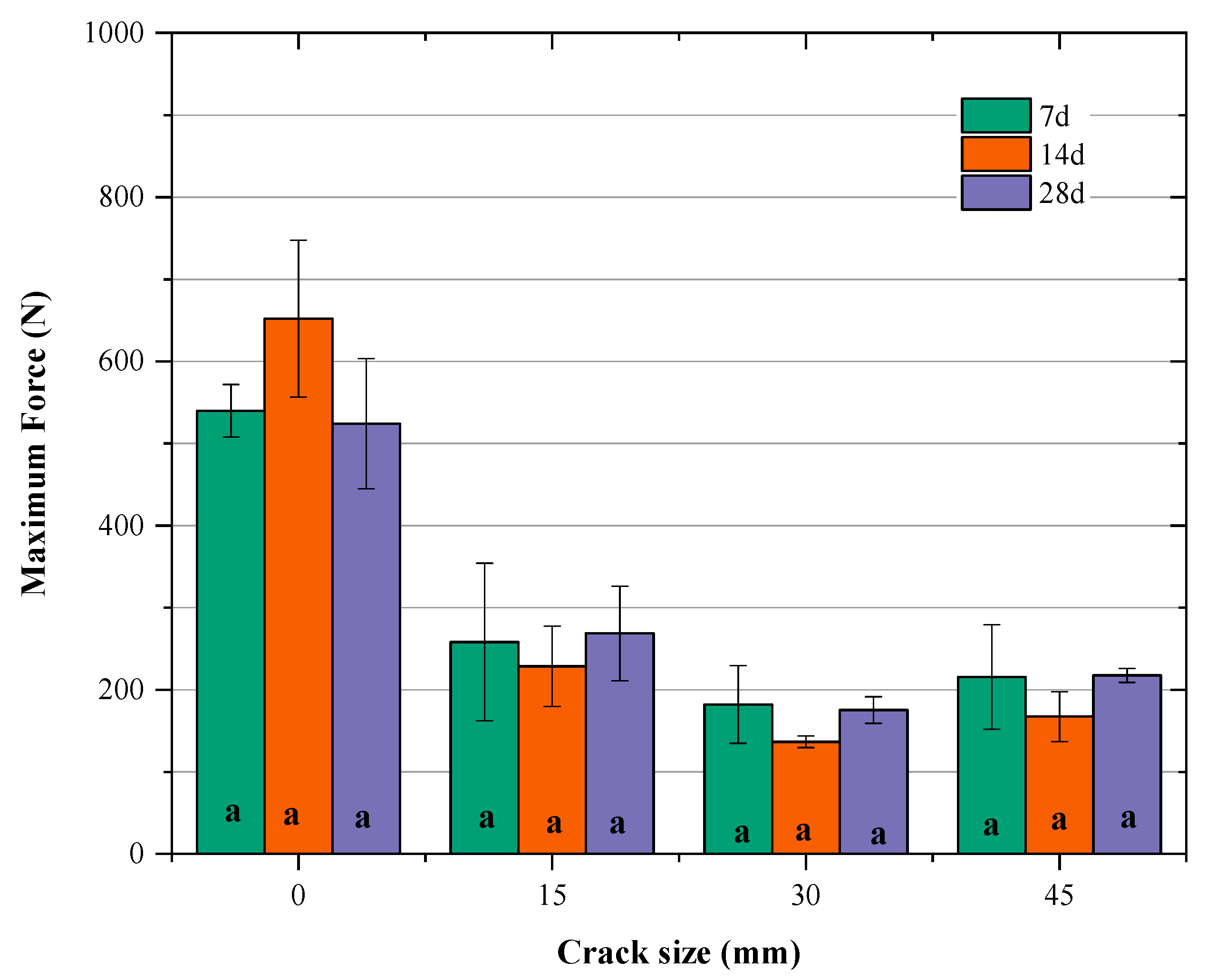
Figure 7 and Figure 8 show the load values of phase 2 and the reduction suffered by the presence of cracks when compared to the maximum load value achieved by the intact samples. Additionally, Table 4 presents a description of the maximum force values. The test of statistical differences between groups (Kruskal–Wallis test), followed by the multiple comparison test (Conover–Iman test), was performed to verify whether the crack had a significant effect on the maximum load of the samples and in which groups this effect occurred. The same letter inside the bars denotes homogeneous groups.
The statistical test shows that the crack had a significant influence on the maximum load values and that this was already noticeable for the smallest crack size (15 mm). The existence of a 15 mm crack, corresponding to a loss of contact of 12.5%, generated a reduction in the maximum force supported by the mortar–ceramic set of approximately 50% concerning the reference sample (without crack) for both types of mortar with 28 days.
When the crack size was increased to 30 mm, doubling the loss of contact, the load capacity fell, after 28 days, reaching 70% of the reference sample. This percentage of loss remains the same in the AMII samples even with the increase in contact loss (45 mm crack).
This significant reduction in the load capacity of the samples demonstrates the high stress-concentrating effect that the existence of flaws in the interface region exerts already in the initial phases of loading. This also reveals the importance of ensuring that the substrate conditions are the best possible, as the gain in adhesion will only be effective if the adhesive mortar covers the entire surface. All of this reinforces the premise that the contact between the surfaces is decisive in the intensity of the bonds existing at the interface, since the acetate sheet, which simulated the existence of the crack, was positioned precisely at the mortar–ceramic interface, directly interfering with adhesion between them.

3.1.2. Effect of Curing Time
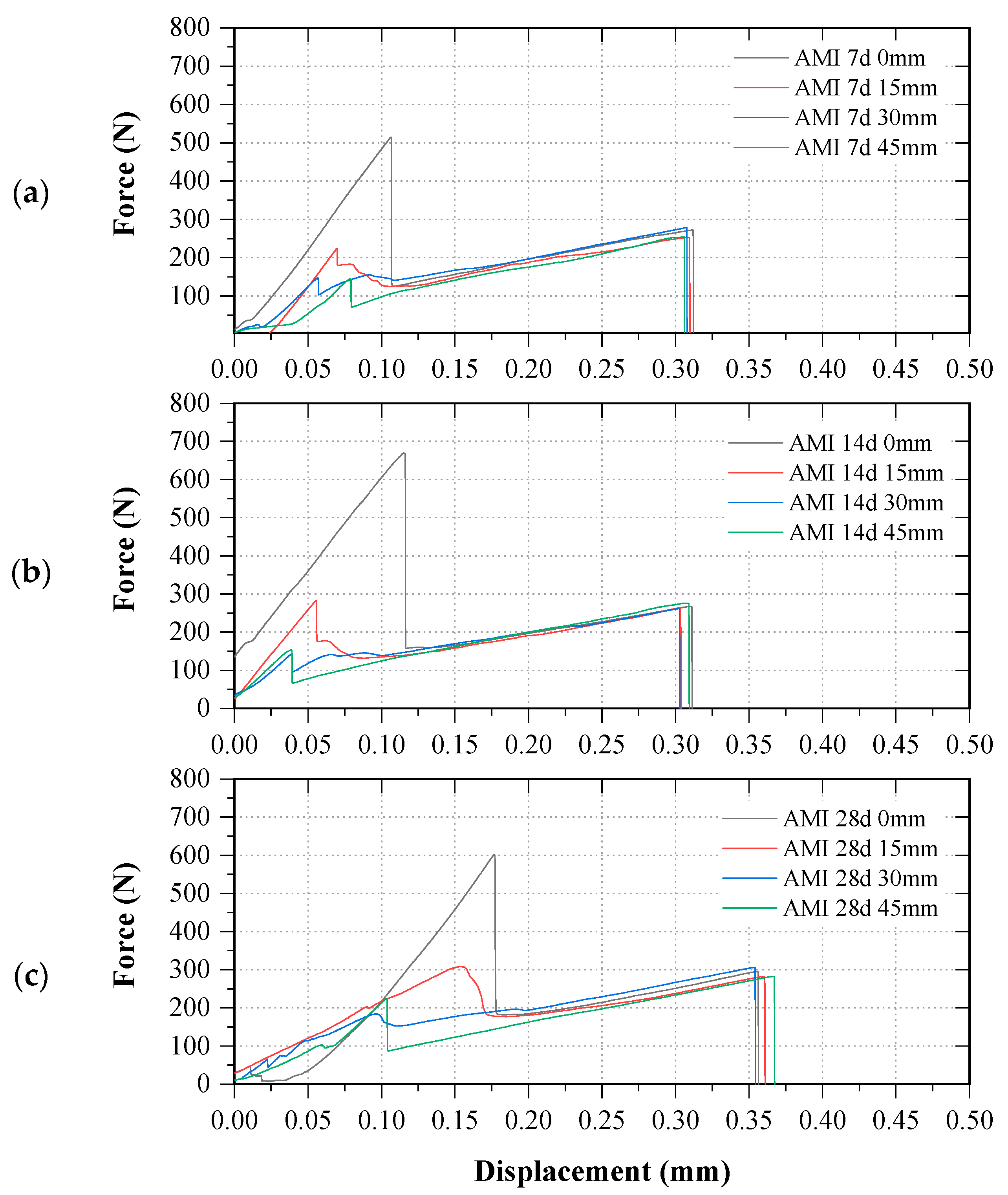
Figure 9 and Figure 10 show the propagation curves as a function of curing time for the two types of mortar. Figure 11 and Figure 12 present the results of statistical tests to verify the effect of curing time on the value of the maximum load reached.
The analysis of the propagation curves seems to reveal a small gain in strength depending on the curing time, with the greatest difference being found in samples with AMII, without previous cracking, when the curing time increases from 7 to 28 days. However, statistical analysis shows that the differences observed in the representative curves, due to healing time, were not statistically significant.
A point that draws attention in Figure 10 is the shape of the propagation curves of the samples with AMII 45 mm, which is more similar to the triangle curve of dry joint ceramic plates. A justification for this change in the shape of the curve can be found in studies carried out by [23], who observed the same change in their curves when an uneven mixture of propagation modes was performed. In this research, this change can be attributed to the large area of debonding promoted by the 45 mm crack, which caused the ceramic to assume the mechanical support of the sample faster, and may have influenced the contribution of the mode mixture.

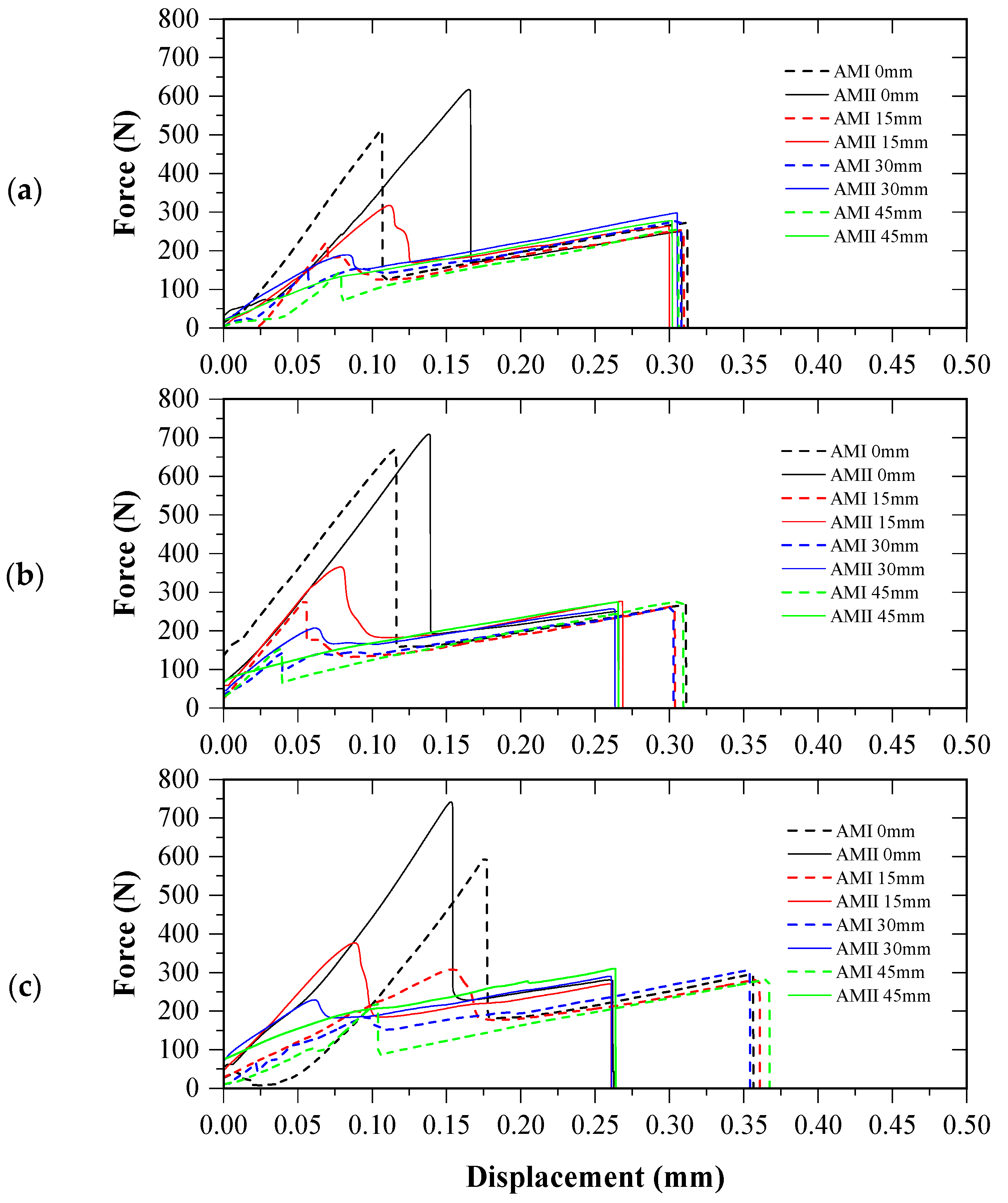
3.1.3. Effect of AM Type

Figure 13 shows the results of the MMF test depending on the type of adhesive mortar. The analysis of the representative curves seems to indicate that the AMII mortar presents slightly better mechanical performance than the AMI, for all curing times evaluated. However, when taking into account the load values of all samples, the application of the Mann–Whitney statistical test, used when wanting to compare two groups of independent samples (AMI and AMII), indicated a pvalue > 0.05, which means that the hypothesis of equality between the average values must be accepted, that is, it is much more likely that the mechanical performance of the two mortars is similar.
In this sense, given the results presented, it is important to highlight the role of interfacial contact on the adhesion between the coating layers, as it was the only variable that influenced the mechanical performance of the samples under study.

3.2. Analysis of Adhesion Using the Energy Criterion

Although load- and stress-based approaches are the subject of a large amount of investigation, this research wishes to investigate whether the analysis of the adhesion of adhesive mortar joints can also be carried out using energy criteria, to quantitatively show the energy that, when placed on the samples, creates fracture surfaces.
For this, the values of potential elastic energy and dissipated energy were extracted from the propagation curves. The elastic energy was obtained from the area under the curve in the section delineated by phases 1 to 3. The dissipated energy was obtained from the difference in areas under the curve of samples with different crack sizes, following the methodology found in [4].
Figure 14 shows the elastic energy values for the two types of mortar depending on the different crack sizes. In this figure, it can be seen that there is a decrease in elastic potential energy as the contact area between the materials is reduced. The reduction in this energy occurs significantly in samples with 15 mm of previous cracking, as observed in previous discussions with the force parameter.
The reduction in elastic energy occurs because the increase in crack size occurs with energy dissipation by the system. Thus, at the end of propagation, the elastic potential energy stored in the system was permanently reduced. The exponential reduction in energy due to the propagation of a crack or the presence of a bonding failure shows that there is a close relationship between the interface energy and the material adhesive strength since the load values of the ceramic/adhesive mortar assembly also suffered significantly. reduction. Lower elastic energy values of the samples indicate lower adhesion resistance when connecting the materials interface.
The influence of curing time on energy values was not observed, as the curves were all within the standard deviation (pvalue > 0.05). The same can be observed with the type of AM which, in general, with rare exceptions, also presented similar energy performance. A plausible justification for this may be the similarity of the mechanical performance of the mortars, observed by the lack of statistical significance in the MMF test.
In research works presented in the literature in which the mechanical properties of adhesives are different [12,24,25], such as tensile strength and modulus of elasticity, it was possible to verify a difference in the energy performance of the material. In [12] the ductile adhesive presented a critical energy of 4 to 10 times greater than the brittle adhesive.
However, the observed results in this research demonstrated that when there is a similar mechanical performance of adhesive mortars, the interface energy is intrinsically related to the substrate conditions in providing better mechanical anchoring of the materials in contact.
An important parameter in predicting the fracture resistance of materials is the critical energy release rate; for this reason, the values of energy dissipated throughout the crack propagation process were calculated and are presented in Table 5 as the standard deviation value (S.D.). A statistical analysis was also carried out to verify the effect of the variables on the dissipated energy parameter which is presented in Table 6. This result reveals that the dissipated energies of the samples assume different values as the size of the pre-crack changes (pvalue < 0.05). Curing time and type of mortar did not have the same influence.
The results presented in Table 5 show that for the samples to progress from a state without cracking to the state of initial cracking (0/15 mm), greater energy dissipation was necessary when compared to the other states.
From Table 5, it is also possible to see that after the crack begins to propagate, its advancement does not require the same release of energy, justifying the lower dissipation values when advancing from 15 mm to 45 mm. This can be explained by the fact that crack growth promotes the accumulation of damage, favouring the coalescing of existing microcracks and contributing to their propagation. Furthermore, once the energy release rate reaches a critical value, Gc, the crack propagates in an unstable manner, that is, it grows without the need for an increase in applied load.
The statistical analysis results presented in Table 6 confirm the previous analysis and, as shown by [26], the energy dissipated (Ed) during the crack propagation process is equal to the critical fracture energy (Gc) of the material, and even that the critical fracture energy can assume the highest value among the dissipated energies by the material throughout the damage propagation process. Therefore, Table 7 presents the Gc values for each AM type and curing times.
Critical fracture energy values confirm the fact that neither the AM type nor the curing time were influencing factors on the energy parameters of the material, as all Gc identified fall within an average value of 0.053 ± 0.031 J. This result is in agreement with the maximum load and elastic energy values observed, which were also not affected by these same variables. In this research, the value of 0.053 ± 0.031 J can be assumed to be the critical fracture energy of the ceramic–adhesive mortar interface, recognizing that it is necessary for the load applied to these samples to dispense energy equal to or greater than this value so that it is possible for a 15 mm crack to propagate and create a fracture surface.
By way of comparison with the results of this research, Table 8 provides a summary of critical fracture energy (Gc) values obtained for different adhesives and substrates.
In this work, it was evident that there is a close relationship between surface energy and adhesion. Thus, the worse the interfacial contact, the greater the energy dissipated through the interface and the lower the amount of energy potentially absorbed by the sample. Therefore, to improve the material’s energetic performance and increase the value of its critical fracture energy, it is necessary to improve the interfacial contact conditions. This was observed in studies [30], in which the surface treatment carried out on a group of samples provided an increase in the critical fracture energy of the samples.

3.3. Limitations of the Study and Future Study Plan

Based on the experimental results presented and discussed above, it is possible to list some limitations of the research, highlighting the following:
  • The existing literature concerning the systematic study of the critical energy of fault propagation in ceramic contacts is scarce or non-existent, as far as the authors were able to verify. In this sense, the research focused on identifying the variation range of energies involved in the evolution of the damage, simulated by reducing the bonded area. Additionally, despite the need to expand the study with a greater number of samples to be tested, especially with shorter damage induction intervals, to assess more accurate values of the determining property of contact conditions (namely, the critical contact energy), the experimental values obtained in this work were close to the experimental values of other systems.
  • Still on the previous point, it is important to highlight that statistical analyses were carried out with the set of samples involved in the study to confirm the accuracy of the experimental campaign and the significance of the studied variables (tensile strength and energy).
  • Only one type of ceramic coating (Bib group), without additional surface treatments, was used to prepare the samples, therefore, other contact conditions could not have their effect investigated on the parameters taken for discussion.
  • The monitoring of the crack propagation could not be carried out. The crack propagations possibly occurred at a microscopic level, so that information about the type of failure can only be purely descriptive, obtaining, from visual analysis, validation that the adhesive failure occurred in all samples, at the upper contact where the acetate film was placed.
However, it was possible to identify, through the experimental tests, that the critical contact energy prevails over the properties of the isolated materials in the structural integrity of the bonded systems. Additionally, given the significance of this parameter for the bonded systems, it should be taken into account that the analysis is quite complex and requires the use of multiple approaches.
To identify the mechanical aspects, taking into account that the characteristics of the contact reside on scales that are often micrometric, it is necessary to expand the study with the use of non-destructive wave propagation techniques, with variation in frequency and amplitude of mechanical waves, which can expand the development of damage detection tools and even allow the creation of numerical models that include contact elements. In turn, the physicochemical aspects allow us to understand the role of mechanical anchoring, through the study of the roughness of the substrates as well as the potential chemical compatibility of the adhesives and their interactions on this scale. To this end, microscopic and microanalytical techniques are essential, such as atomic force microscopy, scanning electron microscopy as well as the chemical contrasts allowed by the use of energy-dispersive spectroscopy, for example.

4. Conclusions

This study investigated the adhesion quality of adhesive mortar joints based on the analysis of their fracture resistance. Ceramic samples joined through a layer of adhesive mortar were subjected to combined tensile and shear stresses, using the mixed-mode flexure test, seeking to grow closer to what happens in building facade coverings.
For this investigation, the effects of some variables were studied, such as different crack sizes, curing time, and type of adhesive mortar. The study of the adhesive capacity of the joints began with an analysis of the propagation curves. The analysis was carried out by subdividing the curves into loading phases. Analysis of the effects of variables was also carried out based on two parameters: load and energy. From the above, the following conclusions can be drawn:
  • The propagation curves provided four phases for understanding the failure mechanism of the sandwich samples, making it possible to identify the region in which the adhesive acts predominantly on the mechanical support of the sample, the moment in which the connection between the mortar and the ceramic tile breaks due to the propagation of the crack;
  • The influence of curing times and types of mortar used were not observed in the MMF test. Even though a difference between the propagation curves depending on these variables could be perceived, the average of the maximum loads reached by the samples was within the standard deviation.
  • The adhesion of the adhesive mortar to the substrate was significantly compromised by the presence of the previous crack, and this effect can be seen from 15 mm cracks when a 50% reduction in its resistance was caused.
  • The loss of adhesion can also be evidenced by the rapid transfer of load support from the mortar to the ceramic tile, noted by the reduction in the section of the curve between phases 2 and 3 and the increase in the region between phases 3 and 4 as it increases the size of the crack.
  • Analysis using energy parameters also confirmed the importance of effective contact between materials. The elastic energy of the system fell with increasing crack length.
  • The exponential reduction in energy due to the propagation of a crack or the presence of a bonding failure showed that there is a close relationship between the interface energy and the material adhesive strength since the load values of the ceramic/adhesive mortar set also suffered a significant reduction.
  • The energy release rate was also calculated, and its greatest detachment was observed when going from a state without cracking (reference) to the initial cracking state (15 mm); from then on, less energy release was necessary to advance from a state of cracking to a larger one.
  • The research also showed that the worse the interfacial contact, the greater the energy dissipated across the interface and the less energy potentially absorbed by the sample. A close relationship between surface energy and mechanical adhesion can be observed.
  • The value of 0.053 ± 0.031 J was adopted as the critical contact energy of the ceramic–adhesive mortar interface in this research, recognizing that it is necessary for the load applied to these samples to dispense energy equal to or greater than this value so that it is possible for a 15 mm crack propagates and creates a fracture surface.

Author Contributions

All the authors contributed to the development, analysis, writing, and revision of the paper: Conceptualization, F.A.N.S., J.S.d.S. and S.M.T.; methodology, Â.J.C.e.S., F.A.N.S., J.S.d.S. and S.M.T.; software, Â.J.C.e.S. and F.A.N.S.; validation, F.A.N.S. and J.M.P.Q.D.; formal analysis, F.A.N.S., J.M.P.Q.D. and A.C.A.; investigation, Â.J.C.e.S., F.A.N.S., J.S.d.S. and S.M.T.; writing—original draft preparation, Â.J.C.e.S. and F.A.N.S.; writing—review and editing, F.A.N.S., J.M.P.Q.D. and A.C.A.; visualization, F.A.N.S. and J.M.P.Q.D.; supervision, F.A.N.S., J.S.d.S. and S.M.T.; funding acquisition, F.A.N.S. and J.M.P.Q.D. All authors have read and agreed to the published version of the manuscript.

Funding

This work is financially supported by national funds through the FCT/MCTES (PIDDAC), under the project 2022.06841.PTDC—BlueHouseSim—Development of numerical simulation tools and methodologies for high-efficient off the electrical grid houses, with DOI 10.54499/2022.06841.PTDC (https://doi.org/10.54499/2022.06841.PTDC). In addition, this work was financially supported by: Base Funding—UIDB/04708/2020 with DOI 10.54499/UIDB/04708/2020 (https://doi.org/10.54499/UIDB/04708/2020) and Programmatic Funding—UIDP/04708/2020 with DOI 10.54499/UIDP/04708/2020 (https://doi.org/10.54499/UIDP/04708/2020) of the CONSTRUCT funded by national funds through the FCT/MCTES (PIDDAC); and FCT through the individual Scientific Employment Stimulus 2020.00828.CEECIND/CP1590/CT0004—DOI 10.54499/2020.00828.CEECIND/CP1590/CT0004 (https://doi.org/10.54499/2020.00828.CEECIND/CP1590/CT0004).

Data Availability Statement

The data that support the findings of this study are available upon request from the authors.

Conflicts of Interest

The authors declare no conflicts of interest.

References

  1. Melo, A.C.; Costa e Silva, A.J.; Torres, S.M.; Delgado, J.M.P.Q.; Azevedo, A.C. Influence of the contact area in the adherence of mortar—Ceramic tiles interface. Constr. Build. Mater. 2020, 243, 118274. [Google Scholar] [CrossRef]
  2. Mansur, P.; Nascimento, L.; Mansur, S. Mapping of Pathologies in Ceramic Coating Systems of Facades. Construindo 2012, 4, 64–82. [Google Scholar]
  3. Wetzel, A.; Herwegh, M.; Zurbriggen, R.; Winnnefeld, F. Influence of shrinkage and water transportation mechanisms on microstructure and crack formation of tile adhesive mortars. Cem. Concr. Compos. 2012, 42, 39–50. [Google Scholar] [CrossRef]
  4. Barros, S.; Champaney, L. Crack propagation tests: Analytical and numerical approaches. In Mechanics of Solids in Brazil 2009; da Costa Mattos, H.S., Alves, M., Eds.; Brazilian Society of Mechanical Sciences and Engineering: Berlin, Germany, 2009. [Google Scholar]
  5. NBR 14081-4; Adhesive Mortars Industrialized for the Settlement of Ceramic Tiles. Part 4: Determination of Tensile Adhesion Strength. Brazilian Association of Technical Standards: Rio de Janeiro, Brazil, 2012.
  6. Garpelli, F.P.; Ramírez, F.M.G.; Sales, R.M.; Arbelo, M.A.; Shiino, M.Y.; Resende, H.B.; Donadon, M.V. Experimental characterization of Mode II fatigue delamination growth onset in composite joints. J. Compos. Mater. 2022, 56, 115–132. [Google Scholar] [CrossRef]
  7. Fernandes, R.L.; Freitas, S.T.; Budzik, M.K.; Poulis, J.A.; Benedictus, R. From thin I’m extra-thick adhesive layer thicknesses: Fracture of bonded joints under mode I loading conditions. Eng. Fract. Mech. 2019, 218, 106607. [Google Scholar] [CrossRef]
  8. Fernandes, R.L.; Budzik, M.K.; Benedictus, R.; Freitas, S.T. Multi-material adhesive joints with thick bond lines: Crack onset and crack deflection. Compos. Struct. 2021, 266, 113687. [Google Scholar] [CrossRef]
  9. Marzi, S.; Biel, A.; Stigh, U. On experimental methods to investigate the effect of layer thickness on the fracture behavior of adhesively bonded joints. Int. J. Adhes. Adhes. 2011, 31, 840–850. [Google Scholar] [CrossRef]
  10. Carlberger, T.; Stigh, U. Influence of layer thickness on cohesive properties of an epoxy-based adhesive—An experimental study. J. Adhes. 2010, 86, 816–835. [Google Scholar] [CrossRef]
  11. Daghayni, H.R.; Ye, L.; Mai, Y.W. Mixed-mode fracture of adhesively bonded CF/ epoxy composite joints. J. Compos. Mater. 1996, 30, 1248–1265. [Google Scholar] [CrossRef]
  12. Saleh, M.N.; Budzik, M.K.; Saeedifar, M.; Zarouchas, D.; Freitas, S.T. On the influence of the adhesive and the adherend ductility on mode I fracture characterization of thick adhesively-bonded joints. Int. J. Adhes. Adhes. 2022, 115, 103123. [Google Scholar] [CrossRef]
  13. Ferreira, L.E.T. Elements of Fracture Mechanics Applied to Structural Engineering: Analytical, Computational and Experimental Aspects; UFLA: Minas Gerais, Brazil, 2019. [Google Scholar]
  14. Sousa, F.C.; Akhavan-Safar, A.; Rakesh, G.; Silva, L.F.M. Fatigue life estimation of adhesive joints at different mode mixities. J. Adhes. 2022, 98, 1–23. [Google Scholar] [CrossRef]
  15. NBR 10545-3; Ceramic Plates: Determination of Water Absorption, Apparent Porosity, Apparent Relative Density, and Apparent Density. Brazilian Association of Technical Standards: Rio de Janeiro, Brazil, 2020.
  16. NBR 13006; Ceramic Plates—Definition, Classification, Characteristics, and Marking. Brazilian Association of Technical Standards: Rio de Janeiro, Brazil, 2020.
  17. NBR 14081-1; Adhesive Mortars Industrialized for the Settlement of Ceramic Tiles. Part 1: Requirements. Brazilian Association of Technical Standards: Rio de Janeiro, Brazil, 2012.
  18. NBR 14081-2; Adhesive Mortars Industrialized for the Settlement of Ceramic Tiles. Part 2: Execution of the Standard Substrate and Application of Mortar for Testing. Brazilian Association of Technical Standards: Rio de Janeiro, Brazil, 2012.
  19. NBR 14081-3; Adhesive Mortars Industrialized for the Settlement of Ceramic Tiles. Part 3: Determination of the Open Time. Brazilian Association of Technical Standards: Rio de Janeiro, Brazil, 2012.
  20. NBR 14081-5; Adhesive Mortars Industrialized for the Settlement of Ceramic Tiles. Part 5: Determination of the Slip. Brazilian Association of Technical Standards: Rio de Janeiro, Brazil, 2012.
  21. Fan, J.; Vassilopoulos, A.P.; Michaud, V. Mode I fracture of thick adhesively bonded GFRP composite joints for wind turbine rotor blades. Compos. Struct. 2024, 327, 117705. [Google Scholar] [CrossRef]
  22. Fan, J.; Karami, J.; Kojouri, A.; Hemelrijck, D.V.; Vassilopoulos, A.P.; Michaud, V. Investigation of bulk adhesive material and thick adhesive joints for wind turbine applications. In Proceedings of the 20th European Conference on Composite Materials, Lausanne, Switzerland, 26–30 June 2022. [Google Scholar]
  23. Carraro, P.A.; Meneghetti, G.M.; Quaresmin, M.; Ricotta, M. Crack propagation analysis in composite bonded joints under mixed-mode (I + II) static and fatigue loading: Experimental investigation and phenomenological modeling. J. Adhes. Sci. Technol. 2013, 27, 1179–1196. [Google Scholar] [CrossRef]
  24. Ogawa, Y.; Naito, K.; Harada, K.; Oguma, H. Proposal of Evaluation Method for Crack Propagation Behaviors of Second-Generation Acrylic Adhesives under Mode I Static Loading. Polymers 2023, 15, 1878. [Google Scholar] [CrossRef] [PubMed]
  25. Ogawa, Y.; Naito, K.; Harada, K.; Oguma, H. Evaluation of crack growth behaviors under Mode I static loading for two-part polyurethane adhesives. Int. J. Adhes. Adhes. 2022, 117, 103152. [Google Scholar] [CrossRef]
  26. Valoroso, N.; Champaney, L.F.A. A damage model for simulation decohesion in adhesively bonded assemblies. Eng. Fract. Mech. 2006, 73, 2774–2801. [Google Scholar] [CrossRef]
  27. Santos, M.A.S.; Campilho, R.D.S.G. Mixed-mode fracture analysis of composite bonded joints considering adhesives of different ductility. Int. J. Fract. 2017, 207, 55–71. [Google Scholar] [CrossRef]
  28. Silva, F.P. Study of Fracture Toughness of Adhesive Joints under Mixed Mode Using the Mixed Model Bending Test. Master’s Thesis, University of the State of Rio de Janeiro, Rio de Janeiro, Brazil, 2019. [Google Scholar]
  29. Ribeiro, J.P.S.M.B.; Campilho, R.D.S.G.; Rocha, R.J.B.; Leal, A.J.S.; Viana, F.A.L. Validation of fracture envelopes of structural adhesives for mixed-mode strength prediction of bonded joint. Fract. Ed Integr. Strutt. 2019, 48, 332–347. [Google Scholar]
  30. Barros, S.; Champaney, L. Crack propagation curves on flexure adhesion tests. Int. J. Struct. Integr. 2013, 4, 396–406. [Google Scholar] [CrossRef]
Figure 1. Schematic view of the test samples (dimensions in mm).
Buildings 14 00670 g001
Figure 2. Mixed-mode flexure test.
Buildings 14 00670 g002
Figure 4. Comparison of MMF curves between sandwich samples and ceramic plates.
Buildings 14 00670 g004
Figure 5. Propagation curves of samples with AMI as a function of crack sizes at different curing times: (a) 7 days, (b) 14 days and (c) 28 days.
Buildings 14 00670 g005
Figure 6. Propagation curves of samples with AMII as a function of crack sizes at different curing times: (a) 7 days, (b) 14 days and (c) 28 days.
Buildings 14 00670 g006
Figure 7. Effect of cracking on the maximum strength of samples with AMI at different curing times. Letters inside each bar indicate statistical differences among groups recovered by Kruskal–Wallis test, followed by Conover–Iman multiple comparison test (pvalue < 0.05, same letter denotes homogeneous subsets).
Buildings 14 00670 g007
Figure 8. Effect of cracking on the maximum strength of samples with AMII at different curing times. Letters inside each bar indicate statistical differences among groups recovered by Kruskal–Wallis test, followed by Conover–Iman multiple comparison test (pvalue < 0.05, same letter denotes homogeneous subsets).
Buildings 14 00670 g008
Figure 9. Propagation curves of samples with AM I as a function of curing time for different crack sizes: (a) AMI 0 mm, (b) AMI 15 mm, (c) AMI 30 mm and (d) AMI 45 mm.
Buildings 14 00670 g009
Figure 10. Propagation curves of samples with AM II as a function of curing time for different crack sizes: (a) AMII 0 mm, (b) AMII 15 mm, (c) AMII 30 mm and (d) AMII 45 mm.
Buildings 14 00670 g010
Figure 11. Effect of curing time on the maximum strength of samples with AMI. Letters inside each bar indicate statistical differences among groups recovered by Kruskal–Wallis test, followed by Conover–Iman multiple comparison test (pvalue < 0.05, same letter denotes homogeneous subsets).
Buildings 14 00670 g011
Figure 12. Effect of curing time on the maximum strength of samples with AMII. Letters inside each bar indicate statistical differences among groups recovered by Kruskal–Wallis test, followed by Conover–Iman multiple comparison test (pvalue < 0.05, same letter denotes homogeneous subsets).
Buildings 14 00670 g012
Figure 13. Sample propagation curves depending on the types of AM at different curing times: (a) 7 days, (b) 14 days, and (c) 28 days.
Buildings 14 00670 g013
Figure 14. Elastic energy of the samples as a function of crack size: (a) 7 days, (b) 14 days and (c) 28 days.
Buildings 14 00670 g014
Table 1. Physical properties of the ceramic plate.
Plate (7 × 13 cm)Dry Weight (g)Submerged Weight (g)Saturated Weight (g)Absorption (%)Porosity (%)Density (g/cm3)
1122.6370.66123.530.731.702.32
2130.1474.95130.80.511.182.33
3132.4976.33133.010.390.922.34
4120.4369.48121.310.731.702.32
5123.9771.75125.761.443.312.30
Mean0.761.762.32
Table 2. Result of type A mortar characterization tests.
RequirementsTest MethodUnitAcceptance Criteria AMIResult
Open timeNBR 14081-3 [19]min≥15≥15
Tensile adhesion strength at 28 daysStandard curing (28 days)NBR 14081-4 [5]MPa≥0.50.50
Submerged curing (20 days)≥0.50.63
SlipNBR 14081-5 [20]mm≤2.00.80
Table 3. Result of the type B mortar characterization tests.
RequirementsTest MethodUnitAcceptance Criteria Result
AMIIAMIII
Open timeNBR 14081-3 [19]min≥20≥20≥20
Tensile adhesion strength at 28 daysStandard curing (28 days)NBR 14081-4 [5]MPa≥0.5≥1.01.0
Submerged curing (20 days)≥0.5≥1.00.6
Kiln curing (14 days, 70 °C)≥0.5≥1.00.7
SlidingNBR 14081-5 [20]mm≤2≤2.00.8
Table 4. Descriptive statistics of the maximum strength values of the samples tested.
Curing Time (days)Maximum Force Values (N)—AMI
0 mm15 mm30 mm45 mm
ForceSDCVForceSDCVForceSDCVForceSDCV
7 d539.8532.055.94258.3195.9037.13181.9847.4426.07215.4963.5129.47
14 d652.2695.6014.66228.4749.0121.45136.567.065.17167.2830.4918.23
28 d524.1779.3415.14268.5557.6621.47175.3016.299.30217.498.603.95
Curing Time (days)Maximum Force Values (N)—AMII
0 mm15 mm30 mm45 mm
ForceSDCVForceSDCVForceSDCVForceSDCV
7 d598.9582.6913.81310.1917.005.48248.5683.8333.73160.6223.5714.67
14 d624.5772.6211.63388.0942.3910.92211.6042.1319.91150.8751.2934.00
28 d769.2577.1510.03357.5341.2511.54230.4464.2427.88206.9920.019.67
Table 5. Dissipated energy (Ed) of the samples.
Curing Time (days)Dissipated Energy (J)—Crack Propagation (AMI)
0/15S.D.15/30S.D.30/45S.D.
70.0230.0100.0060.007−0.0010.003
140.0460.0090.0090.0060.0030.001
280.0220.0100.0140.0110.0050.003
Curing Time (days)Dissipated Energy (J)—Crack Propagation (AMII)
0/15S.D.15/30S.D.30/45S.D.
70.0270.0040.0100.0060.0050.004
140.0130.0070.0160.0150.0090.005
280.0530.0310.0040.0180.0170.012
Table 6. Kruskal–Wallis test to evaluate the effect of cracking, curing time, and AM on the dissipated energy parameter.
VariablesDissipated Energy
Hpvalue
Crack48.310.00
Curing time0.820.66
AM0.390.53
Table 7. Critical fracture energy (Gc) of the samples.
Curing Time (days)Critical Energy (J)
AMIS.D.AMIIS.D.
70.0230.0100.0270.004
140.0460.0090.0130.007
280.0220.0100.0530.031
Table 8. Critical fracture energy of the materials.
TestAuthorSubstrateAdhesiveAdhesive Thickness (mm)Gc (N/mm)
SLBSantos and Campilho [27]Polymer and carbon fiber compositePolyurethane15.5
Epoxy10.1
MMBSilva [28]SteelEpoxy0.90.228
SLBRibeiro [29]AluminumEpoxy0.20.11
MMFBarros and Champaney [30]Aluminum (with surface treatment)Epoxy0.50.08
Aluminum (without surface treatment)0.50.04
Disclaimer/Publisher’s Note: The statements, opinions and data contained in all publications are solely those of the individual author(s) and contributor(s) and not of MDPI and/or the editor(s). MDPI and/or the editor(s) disclaim responsibility for any injury to people or property resulting from any ideas, methods, instructions or products referred to in the content.

