1. Introduction
The paper presents the progress of the research team regarding the use of machine learning in combination with 3D scanning techniques for the detection of defects on the surface of various elements of a building, such as walls, pillars, stairs, ceilings, foundations, and others.
In a previous paper, the research team analyzed the possibility of using some of the experience that it gained from the development and practical implementation of certain applications as a starting point in the development of a machine learning-based 3D scanning application in the construction domain. It is worth mentioning that LiDAR and ZED camera systems were used in acquiring real images of both interior and exterior parts of certain buildings [
1].
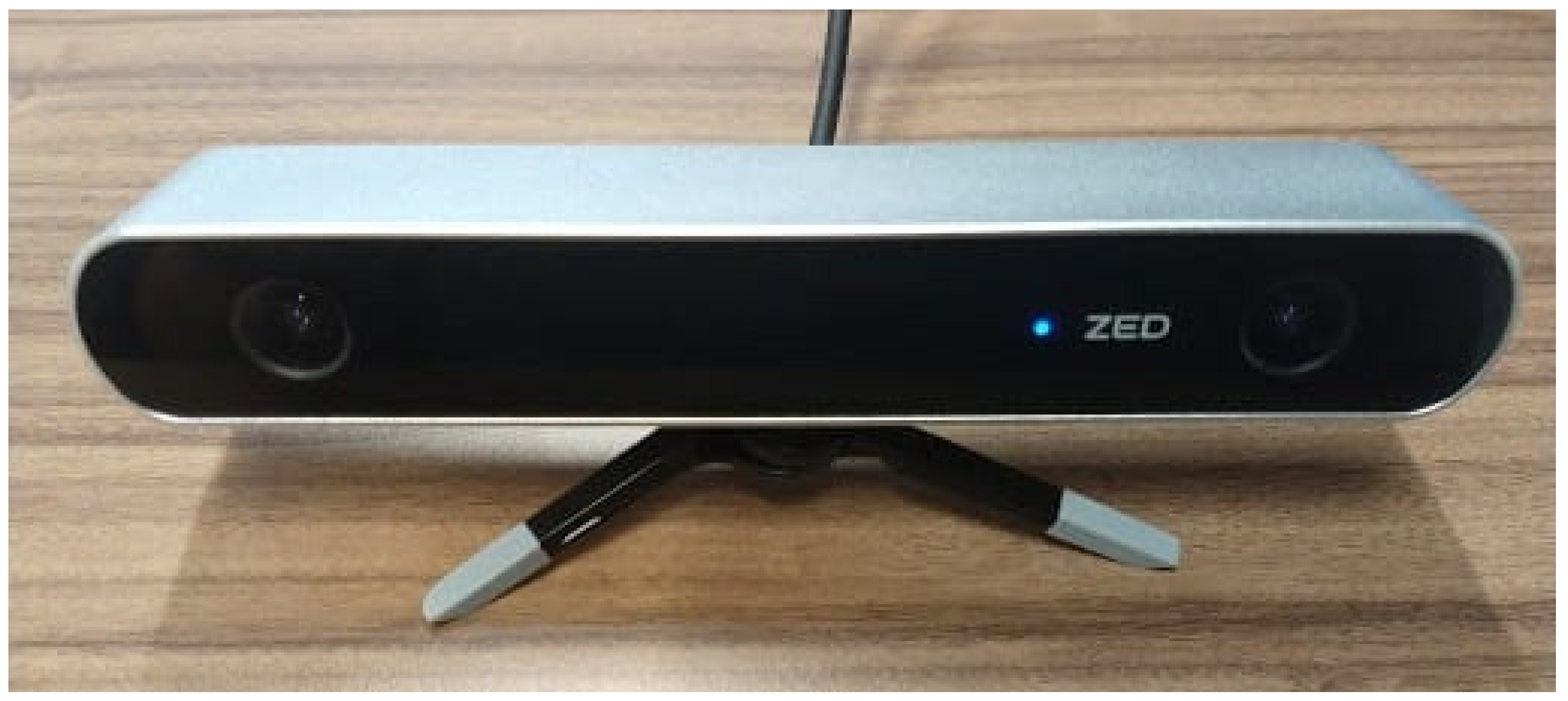
In the current paper, the team presents the development of a machine learning-based application that uses the Python programming language and the PyTorch library v2.2.0. The team used the Zed camera system for the acquisition of real images of different building elements; the images were then used in combination with standard building images to train the artificial intelligence model to recognize different types of damage or defects on the surface of the aforementioned building elements.
The aim of the research team is for the proposed application to scan and classify the defects in real time whilst using components available on the market, such as the Zed camera and a standard laptop or computer, thus keeping the cost of the solution low and affordable. The cost of a Zed camera is around USD 500, compared to the scanners usually used in the construction domain that range anywhere from tens of thousands to hundreds of thousands of dollars. Due to its cost-effective nature and its small size factor, the solution provides a small initial investment and lower lifecycle costs, which makes it practical not only for big construction companies but also for smaller contractors.
2. Related Work
Machine learning techniques have been adopted by some researchers in the construction domain, and it has been proven that they perform well in tasks such as design automation, automatic control, and optimization in intelligent buildings [
2]. This success led to computer vision techniques also being studied by researchers; thus, they have become more capable of automatically detecting surface defects and eliminating the drawbacks of the classic defect detection models [
3].
In their paper, Konstantinos Bacharidis et al. presented a methodology for the accurate 3D realistic façade reconstruction of cultural heritage buildings. Their goal was to use deep neural network architectures used for image segmentation and depth prediction to detect structural elements and generate simulations of the surfaces of the buildings scanned. One of their challenges involved differentiating between certain elements of the design that were the key to differentiating modern buildings from historical buildings. Several technologies were used for scanning, such as terrestrial laser scanning and close-range photogrammetry, to produce point cloud maps. To compensate for the weaknesses of laser scanning, such as glass windows, walls, and doors, additional sensors were used when needed, such as geodetic stations and optical camera sensors; thus, the laser distortion effects were reduced. The point clouds are combined with laser scanning data and are used to simulate photo-realistic reconstructions of the surfaces. The proposed framework enhances the automation and the applicability of building surface scanning by utilizing deep learning techniques [
4].
Compared to the previously mentioned work, the solution presented in this paper uses an optical camera (i.e., a Zed camera system) instead of a LiDAR system, which is more expensive and, as discovered in the previous works of the research team, more sensitive to infrared light when working outside. Their paper represents a basis for the differentiation between cracks and shadows or stains in our solution, as presented below.
Remote sensing technologies play a crucial role in surveying and scanning the complex geometries and architectural features of historical buildings. In their work, Gustavo Rocha et al. explain the use of 3D laser scanning and photogrammetry in the development of a methodology to obtain a consistent model that can help with the restoration or conservation of historical buildings. The 3D scanning makes it possible to integrate the real-life building in a building information modeling system that allows the restorers to take advantage of certain benefits, such as design alternatives, cost estimates, material quantifications, data management, as-built documentation, constructive state analysis, execution plans, and many others. It is extremely important to ensure that the measurements and scans are as precise as possible since heritage buildings need to be preserved with as much detail as possible. Therefore, BIM (building information modelling) is not just software, but an integrated collaborative methodology centered on a building model that represents the real-life status of the building and contains accurate information about it. The integration of BIM into the 3D scanned point cloud data has proven to be a crucial but difficult step in the development of an integrated system. If used correctly from the first step, a BIM model becomes essential to the success of such an application. In their work, the authors also mention that the operator’s experience is crucial at all stages because the use of laser scanning and photogrammetry equipment requires knowledge of architecture and building techniques. The method presented is mostly conducted manually, with only a few automatic processes used for the 3D reconstruction of the topographic surface [
5].
Gustavo Rocha’s work serves not only as a basis for the future development of the solution presented in our paper into an autonomous system for the non-invasive scanning of building surfaces; it also helps the research team to have a better understanding of the capturing of façade details, which has proven to be critical for the correct prediction of defects during the training phase of the artificial intelligence model.
Analyzing the potential of 3D scanning for construction management purposes was covered by Matej Mihić et al. in their work. The goal of their research was to find out whether the construction industry was open to change and whether they could justify the higher cost compared to that of traditional monitoring techniques. One of the technologies studied is LiDAR, which is the most accurate vision-based sensing technology for producing high-resolution point clouds. Photogrammetry is another popular vision-based sensing technology that can generate 3D point cloud models from 2D images. This technique involves image processing and makes the classification of objects possible. The possibility of collecting data with the help of unmanned aerial vehicles or terrestrial automated vehicles is also presented in this paper. The UAV, for example, can provide more comprehensive 3D clouds that also include data from the roofs of the buildings, rather than only from the walls. The most common UAVs used are multirotor drones, due to their robustness, maneuverability, low purchase and maintenance costs, hovering ability, vertical take-off, and landing. In combination with depth cameras, they can create 3D models of buildings in innovative ways [
6]. This paper represents a basis for the planning of the future work on the application that is presented in our research paper.
The research team involved in the present article worked with LiDAR sensors in a previous research project, using the sensory system to scan various hallways, pathways, access doors, and obstacle-filled spaces in a building. They used the depth data from the LiDAR point cloud, which were associated with the RGB data for each point to simulate certain objects from the data captured [
7].
It is worth mentioning that on the construction sites, the conditions are not always ideal. The experience gained during this previous work offered the research team good knowledge about and insight into the best practices for scanning in various environments. It allowed the team to capture the best possible training images, which led to better results in the training loss and the training accuracy. This was later observed in the predictions made by the model, which were more correct.
Convolutional neural networks and transfer learning methods can be used together to help identify the condition of historic building facades. Transfer learning accumulates the knowledge gained by resolving problems in the past and uses it to solve new similar problems [
8]. This possibility is studied by Sumaiyah Fitrian Dini et al.; they present the application of deep learning in the field of architecture for building feature classification and recognition. In their paper, the authors focus on identifying the styles and functions of buildings in urban areas; they also focus on the construction era and period and the automatic detection of defects and damage to buildings. The neural networks have also been applied for the automatic detection of concrete cracks, mold, damage, and stains in images and for the detection of real-time building damage based on terrestrial images. The authors acknowledge that the limited amount of datasets significantly influenced the training and testing processes; therefore, it is advisable to use a correct and large enough dataset when training the artificial intelligence model used in the application presented in the following chapters [
9].
Their work helped the research team to assess the number of images needed to build a proper dataset for our application. As shown in their paper, a small number of images can lead to low prediction accuracy.
A method for crack detection is detailed by Stamos Katsigiannis et al. in their paper. The approach they use is based on a pre-trained deep convolutional neural network optimized for feature extraction, particularly crack detection. Non-destructive techniques and photogrammetry have been used for the inspection of brick buildings, but manual inspection is not time-effective, and it can lead to errors. The presented detection methods reduce the time needed for the work to be completed [
10]. Transfer learning was used to address this gap by classifying brickwork images as cracked or normal. They used images from historical buildings in combination with images acquired from online sources. The main contribution of this research includes the public release of an image dataset for crack detection on brick surfaces and a comparative study of widely used pre-trained convolutional neural network models adapted for crack detection using transfer learning. The results showed that the method used achieved 100% accuracy using libraries such as the MobileNetV2, InceptionersNetV2, and Xception-based models. The MobileNetV2 model was the most efficient one due to its small size, which makes it ideal for handheld devices and autonomous vehicles [
11]. This paper has two important points of interest for our work, namely the use of both images acquired from the facades of real historical buildings and stock images from online libraries; the second point is the use of an artificial intelligence model that does not use a lot of resources, making the application light enough to be used on drones or other types of automatically guided vehicles.
4. Solution Overview
By its nature, the hardware solution composed of readily available equipment ensures a high compatibility between each individual component. The Zed camera is compatible with any platform that recognizes universal video class devices; therefore, it is compatible with any platform that can support the Linux operating system, be it a laptop, desktop, Raspberry Pi, etc. The PyTorch library is supported on Linux versions newer than 15 July 2012; therefore, there are many versions that could be used and that are compatible with an even larger number of devices, thus ensuring the overall compatibility of the solution with a large number of equipment combinations (Laptop, Linux OS, Zed camera).
For the software solution, the research team considered two artificial intelligence training models, namely ResNet50 and ResNet101. The deep residual network architecture (ResNet) is presented in [
21] as a powerful model for image recognition. Some defects are similar and are categorized according to the criteria of the researchers; for example, in the detection of surface defects on steel, there are contusions [
20], protrusions [
22], abrasions [
23], wrinkles [
24], rubbing [
25], and dents [
26]. Similarly, in the construction domain, there are many defects present on the surface, such as cracks, paint chips, stains, and many more; the standardization of these defects is proposed by Macarulla M. et al. in their paper [
27]. Each of the models was first trained and tested on an online image library of various pictures of walls, with or without the aforementioned defects.
The next phase of the training involved the capturing of real-life images of walls from different construction sites. As in the online library, the walls were split into two categories: walls with no apparent defects and walls that presented defects. The models were then tested on real-life images, and the research team documented the results and chose the training model that best suited our needs. As Hongyu Xu et al. presented in detail in their paper, it is very difficult to analyze the large volume of captured images without the help of artificial intelligence; thus, the team was inclined to choose the more capable model [
28].
In the following chapter, the tests and the results are presented for each of the models in both situations: the online library and the real-life images captured by the team.
4.1. Results Using the ResNet50 Training Model on an Online Image Library
The research team started with the ResNet50 training model and with an online image library that consists of pictures of walls split into two sections. One section is composed of pictures of walls that have no cracks or other kinds of damage, and the other section is composed of pictures of walls that present defects such as cracks.
In the development of the presented solution, the team used a well-established technique based on a training model which is part of the ResNet (residual network) family. The training model was a convolutional neural network (CNN) architecture composed of many layers (i.e., 50 layers for ResNet50 and 101 layers for ResNet101). A neural network is an architecture composed of an input and an output layer, and between them, there is a large number of hidden layers that are connected and work in parallel [
29]. The larger the number of hidden layers, the deeper the neural network becomes [
30]. The ResNet architecture allows gradients to flow more directly through its layers; instead of learning the mapping directly from the input to the output of the layer, it learns the residual mapping, which is added to the output of the layer. This makes it easier to train deep networks without losing performance. ResNet is trained using supervised learning with large-scale datasets, and the parameters of the network are updated constantly with algorithms like stochastic gradient descent (SGD). The model can be used for tasks such as image classification, object detection, and image segmentation, which makes it optimal for our approach.
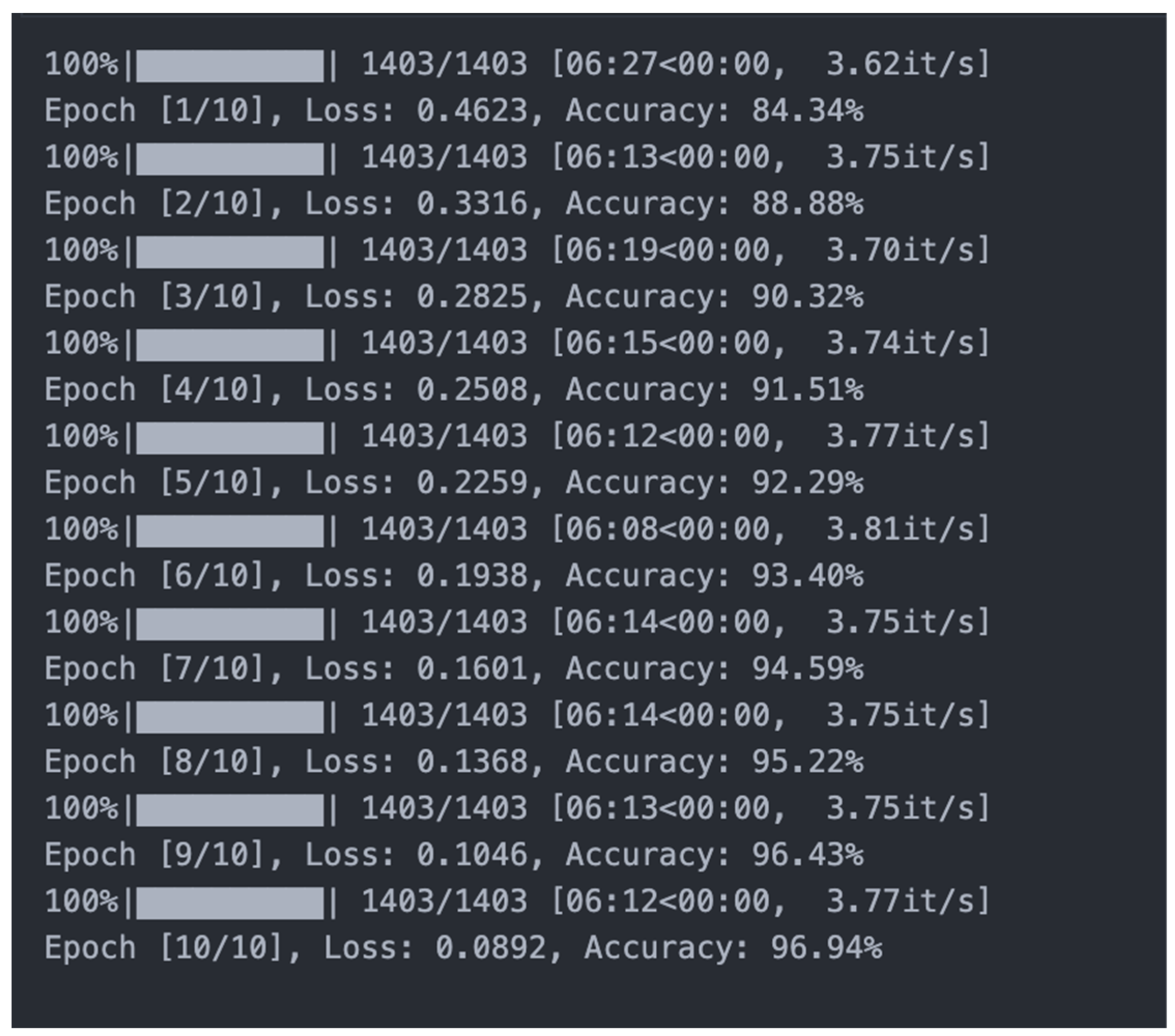
Using the ResNet50 training model, the team ran the training for 10 steps of training for the entire set of pictures, which added up to a total of approximately 140 min. During each step of training, the training accuracy can be seen to improve, as shown in
Figure 2.
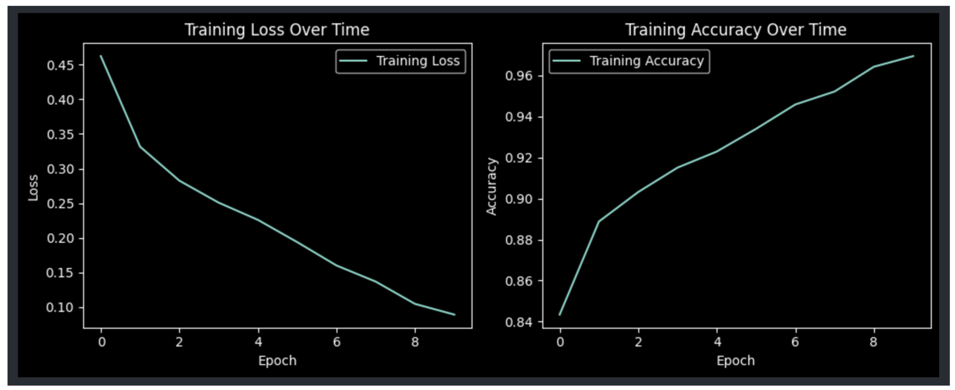
The goal is to train the model until the point where the training loss is minimal and the training accuracy is as high as possible, as shown in
Figure 3. The values of the hyperparameter configuration (learning rate, batch size, etc.) are based on the used hardware; in this case, Apple Neural Engine from the M1 Pro was used.
A pre-processing procedure was applied to all images when creating and defining the dataset in order to have a uniform image size and format (resizing of the images, grayscale transformation if needed). Also, the dataset was split, and 25% of the images were used for the testing of the model; the remaining 75% were used in training. The last layer of the RestNet50 model was replaced with the custom classes needed for the wall classification.
The final test accuracy of the automatic detection can be seen in
Figure 4. The accuracy is affected by the small dataset and by the low resolution.
4.2. Results Using the ResNet101 Training Model on an Online Image Library
The second step was to combine the available dataset with the new images acquired by the research team from the damaged or undamaged buildings to produce a new set of images. This new dataset was initially used for training a new ResNet50 AI model but with poor results. The training results were promising but when used for inference on real images, the model was not able to classify with an acceptable accuracy.
With this in mind, an upgrade of the training environment was considered, and a ResNet101 neural network was set in place; also, the last layer used for classification was replaced with our custom classes of damaged or undamaged buildings. The model parameters used for both models during the training are presented in
Table 1.
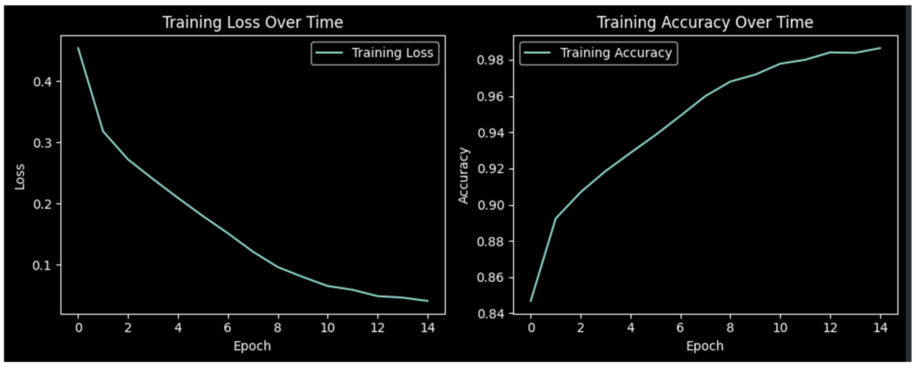
By comparing the graph of the training loss and training accuracy shown in
Figure 3 with the graph shown in
Figure 5, it can be observed that the graphs follow the same general behavior, but in the case of the ResNet101 model, the training loss decreases faster (0.3316 loss for ResNet50 vs. 0.3182 loss for ResNet101 at step 2), and the training accuracy improves in a shorter time right from the beginning (88.88% training accuracy for Resnet50 vs. 89.24% training accuracy for ResNet101 at step 2).
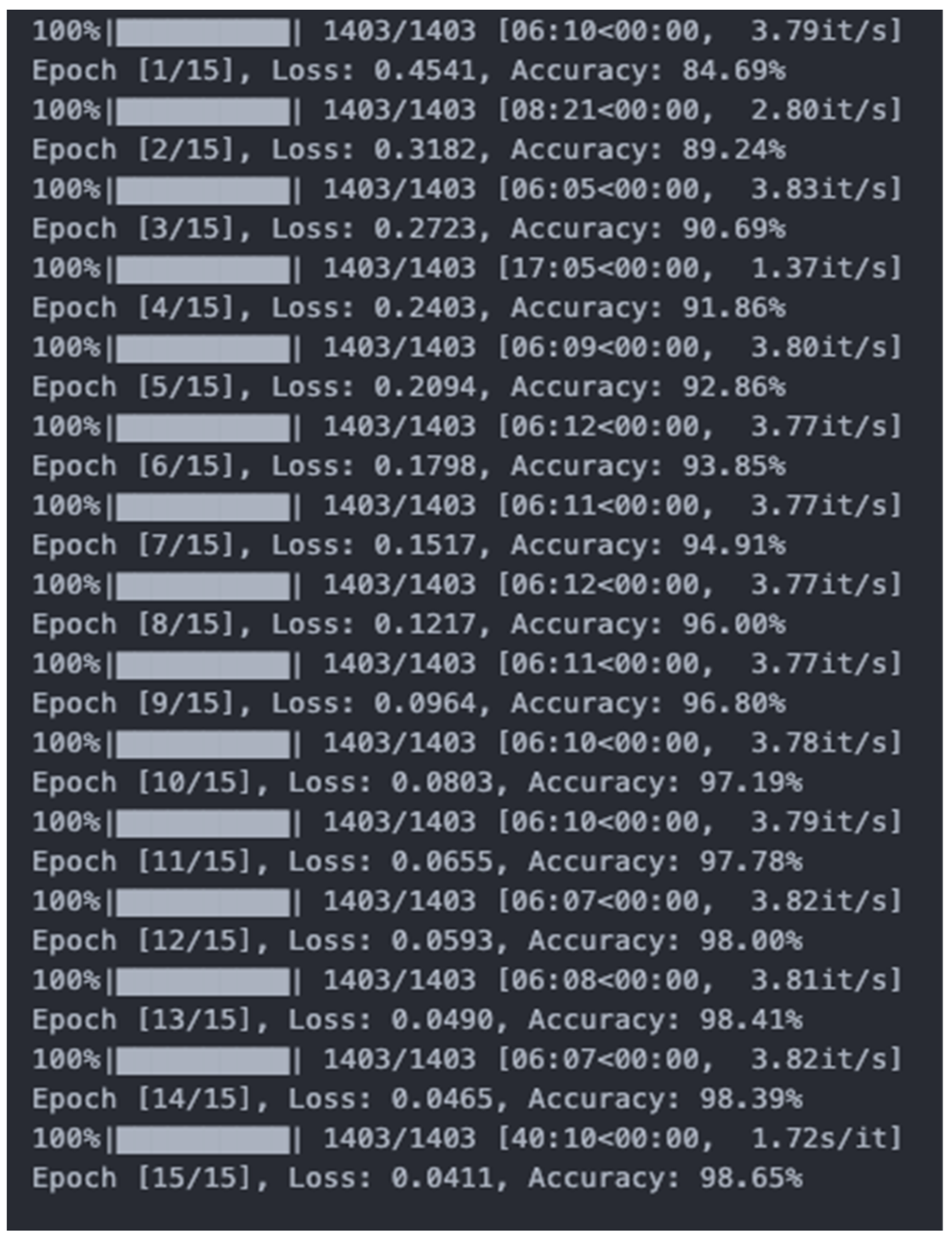
Also, as can be observed in
Figure 6, running the training for more steps (15 steps for the ResNet101 model vs. 10 steps for the ResNet50 model), allows the training accuracy to increase up to 98.65%, compared to 96.94%.
The results of the detection test accuracy of the ResNet101 model reached 91.63%, as shown in
Figure 7, compared to 92.06% in the case of the ResNet50 model.
The training of the model was successful; it had a low error and a high training accuracy, presenting a testing accuracy on real images of 95%. This low testing accuracy is determined by the more complex dataset used in training with more complex features in the training images. Even if the testing accuracy determined during training was not that high, the generated model performed well during testing, with real, previously unused images.
4.3. Results Using the ResNet101 Training Model on Real Images Captured by the Research Team
The team chose the ResNet101 model because it had better results when applied to real-life images; the team used it on a new dataset that consisted of real images captured by the research team. The dataset had the same structure as the online image library, meaning that there were two parts, one consisting of images of walls with no defects and the other containing images of walls with various surface defects such as cracks or holes. This practice is also used in Yusnur Muhtar et al.’s paper, where for each image of a handwritten signature, half of the images contain good samples and the other half contain forged samples [
31].
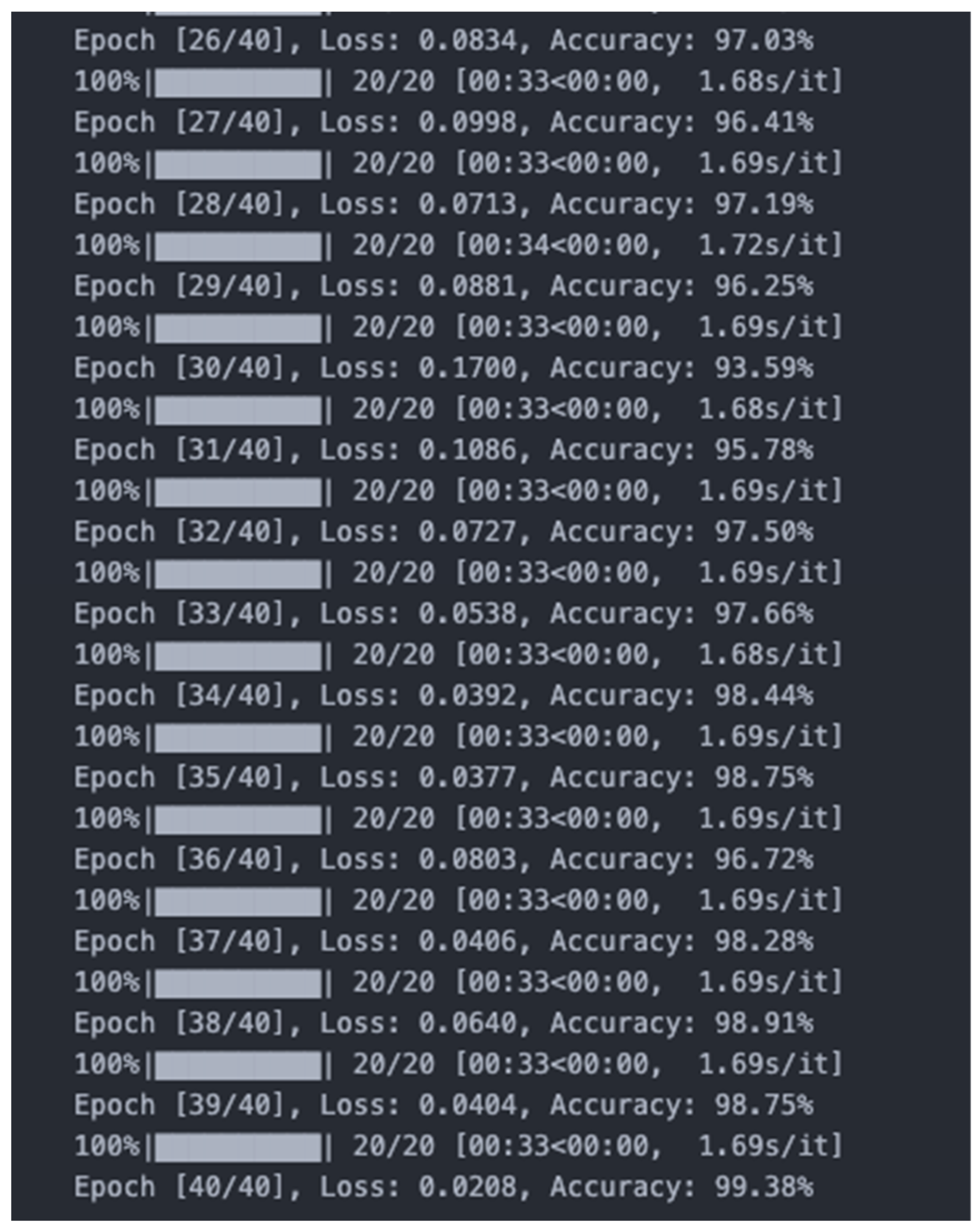
Because the dataset was smaller than the online image library, with a total of 800 images, the research team decided to run the training for 40 steps, which added up to over 200 min of training.
As expected, the accuracy of training increased with each step, reaching 99.38%, as can be observed in
Figure 8.
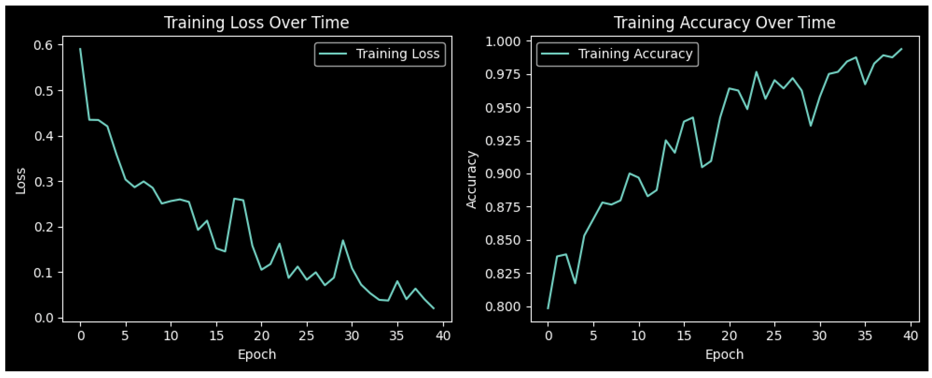
In this case, the graphs of the training loss and training accuracy do not follow a smooth path like that in the previous cases. As can be seen in
Figure 9, both graphs vary slightly during the training period, but both tend towards a general path of improvement over time. The fluctuation may be caused by the quality of the images captured by the team, showing the importance of the quality and reliability of the pictures being captured and the need to take into account natural factors, such as lighting, haze, shadows, etc., as mentioned by Hongpan Lin et al. in their paper [
32].
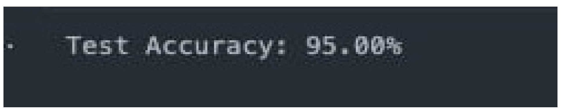
The results of the detection test accuracy were not as high as expected, reaching 95%, as shown in
Figure 10, but the research team has a strong belief that the results could be improved if the dataset was refined in the future and contained only clear images.
On the other hand, this application is meant to be used in a real construction environment where the conditions are not always perfect; thus, not-so-clear images were introduced into the dataset to simulate the real-life conditions found on the working sites.
Some tests were made with the final trained model using real images captured by the research team on real construction sites. The results can be seen in
Figure 11,
Figure 12,
Figure 13 and
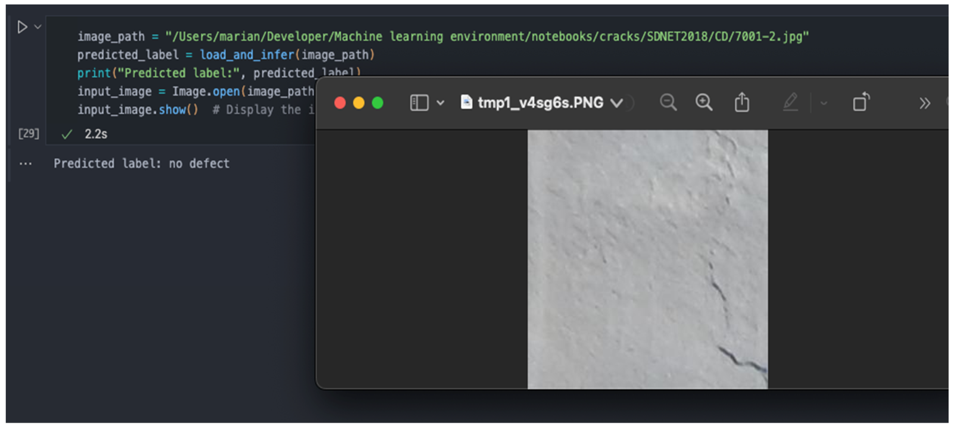
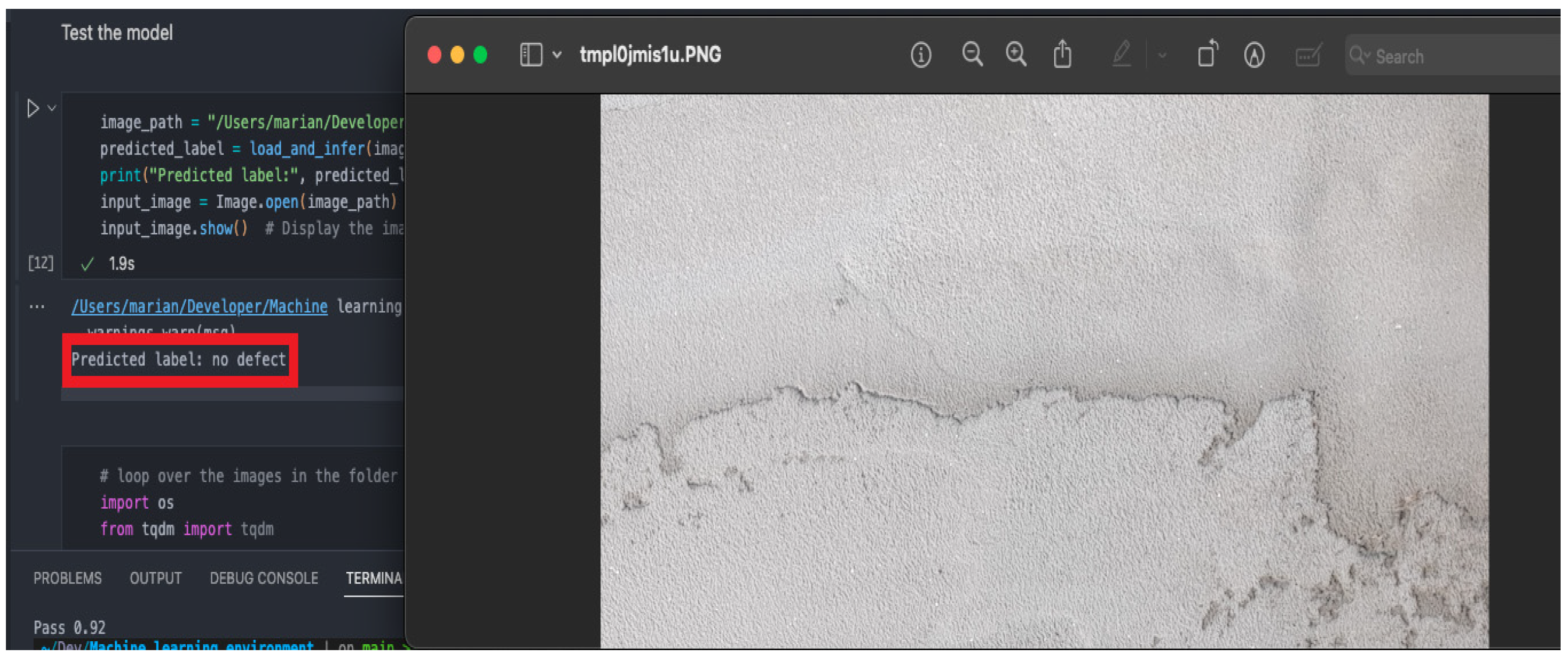
Figure 14, where the application correctly identifies an image with or without any cracks/defects and knows how to detect the difference between a crack and a shadow.
The difference between a simple image-processing algorithm and the machine learning solution used in our paper can be observed in
Figure 11 and
Figure 12. A simple image-processing algorithm mainly uses edge detection to detect cracks; therefore, such an approach could be deceived by features that are similar to cracks (i.e., shadows or stains), and this could lead to fake positives. Our model uses a set of labelled crack images, with which it learns to differentiate between similar features; therefore, as it can be observed being highlighted in the red box, it correctly predicts that the stain and the shadow do not represent a structural defect (i.e., a crack).
If the labelling of defects is performed properly in the first steps of training, the model can differentiate between different types of surface damage according to the labelling on which it was trained. This feature makes the model a versatile one that can be adapted to meet the needs of each construction site.
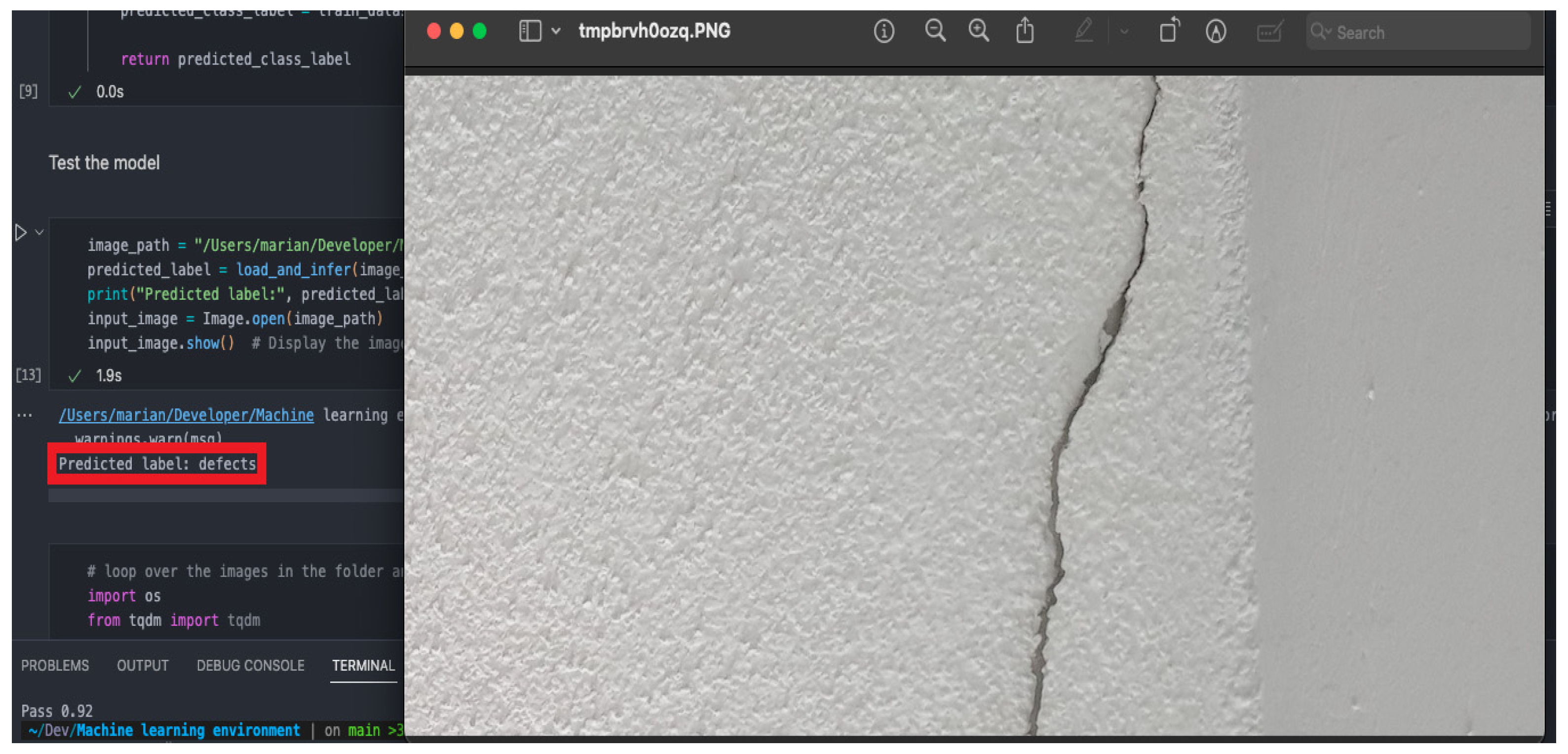
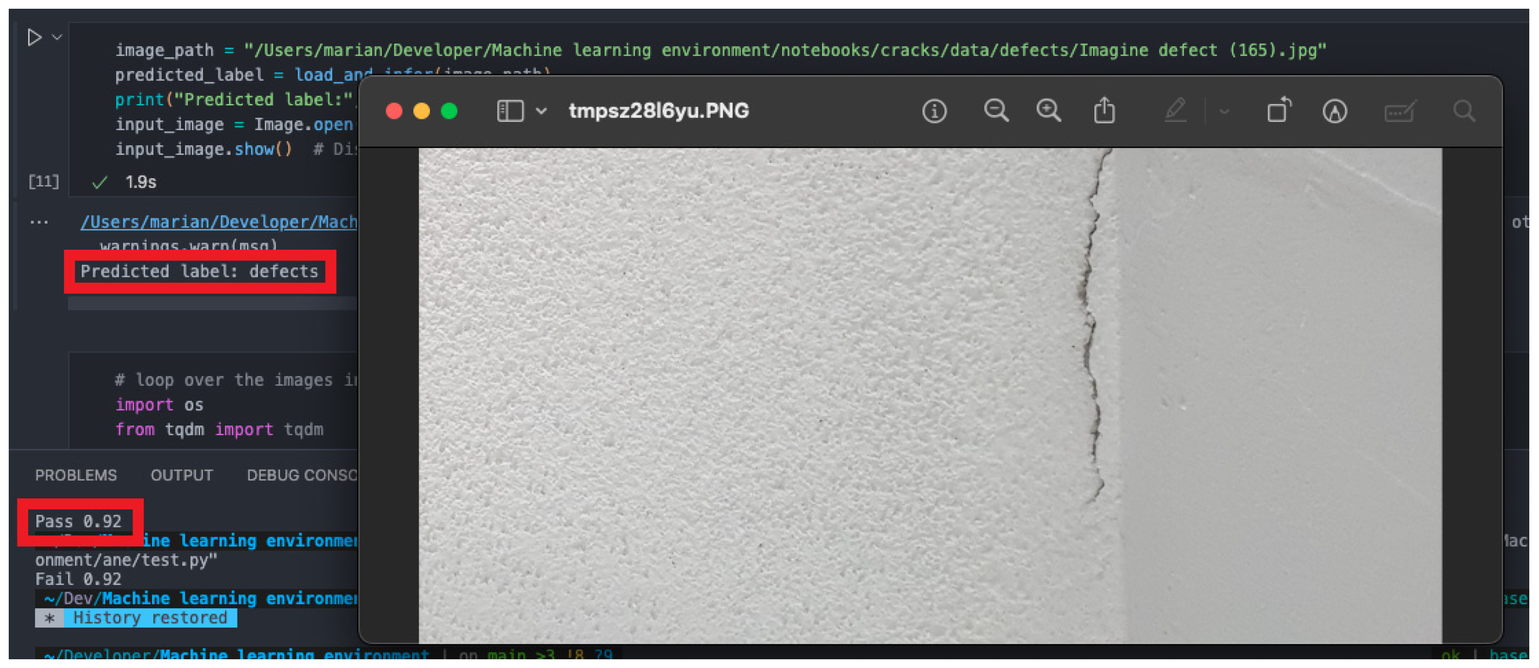
Shown above in
Figure 13 and
Figure 14 and highlighted in the red boxes are the results of the approach chosen by the research team. The solution (i.e., the ResNet101 training model) can correctly predict structural defects with high accuracy (i.e., 92%) on real images, and as shown earlier, its accuracy does not decrease when confronted with naturally occurring factors on a construction site, such as stains or shadows, which proves that it can be used for future work in this domain.
4.4. Further Testing on a New Set of Real Images Captured by the Research Team
For further testing and the checking of the trained model, the research team captured a new set of approximately 230 more real-life images. Out of these, 56 of them presented walls with defects such as cracks or paint chips and the other 176 presented walls with no defects.
The team adopted a three-step procedure for this test: first, the model was tested only using the 176 images with no defects; then, it was tested with the 56 images that presented surface defects; lastly, the team used the entire set of 230+ images, both with and without defects, to test the model.
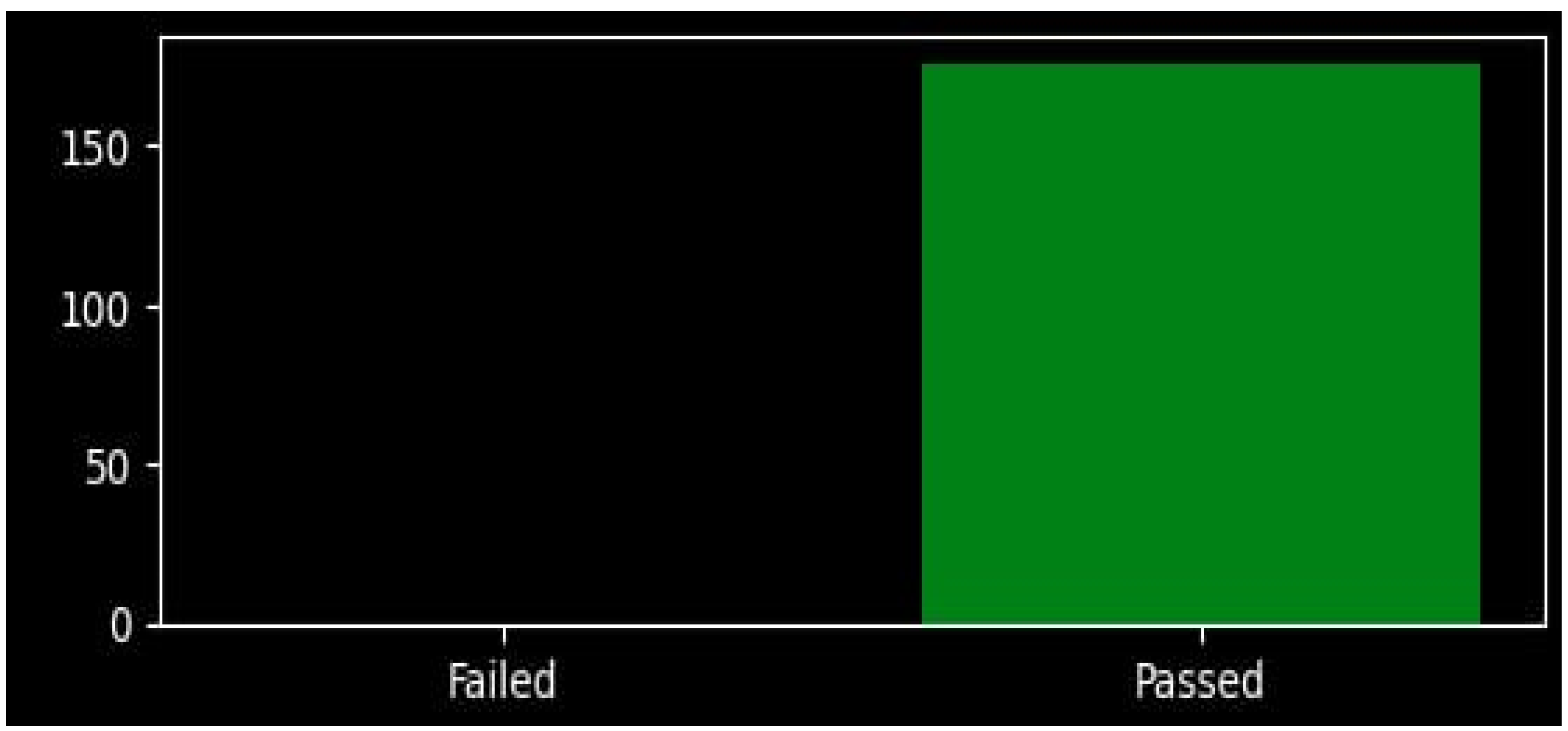
For the first step, just as predicted, the model passed all 176 images with no defects, as shown in
Figure 15. Based on these positive results, the team is confident that the model is able to identify a picture of a wall with no cracks or defects.
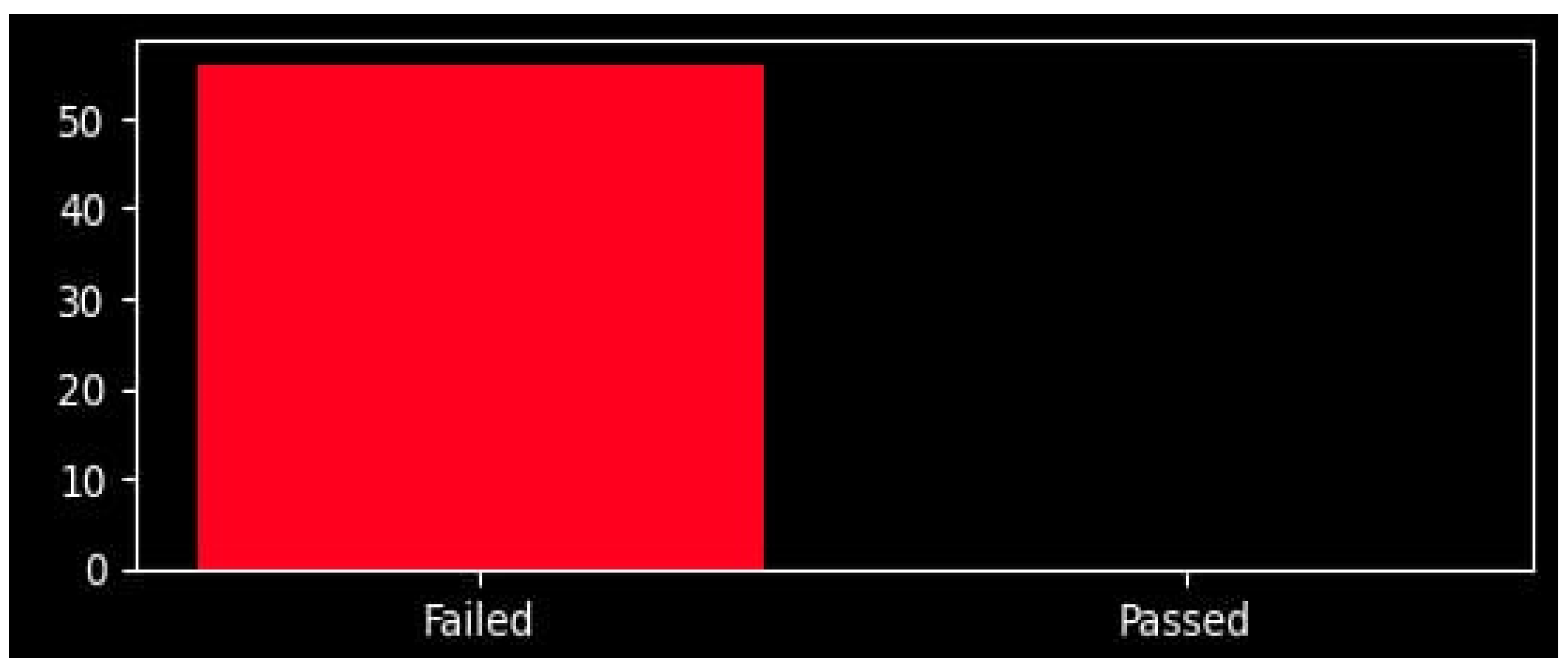
For the second step, the model failed all 56 images that presented surface defects, as can be observed in
Figure 16. Therefore, we can state that in these controlled conditions, the model can correctly identify an image with a wall that presents faults such as cracks, holes, or other similar surface defects.
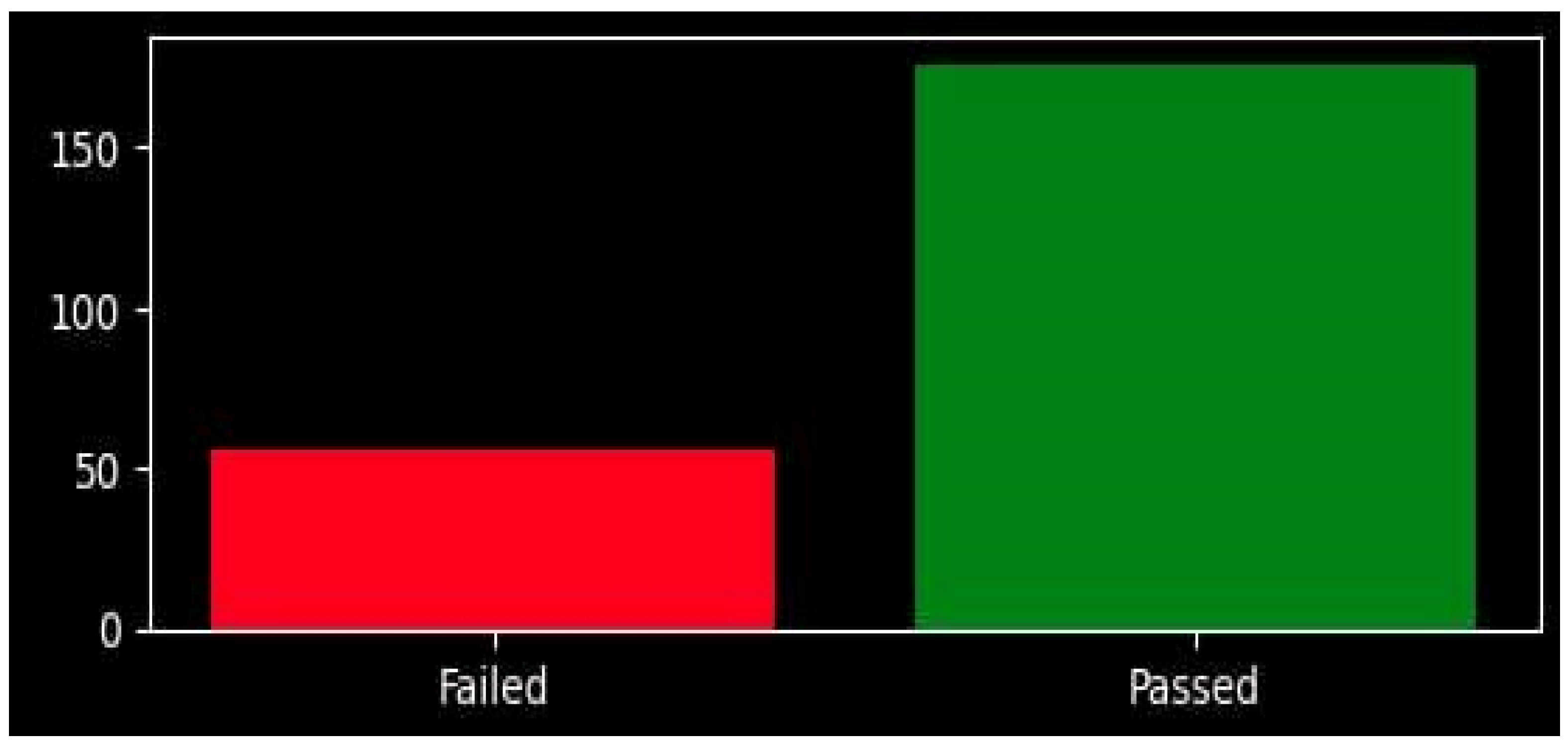
For the last step, the model correctly identified both types of images (with and without defects) with high accuracy, as shown in
Figure 17. The research team is confident that in laboratory conditions, where the images are captured in good lighting conditions and without noise, that the model is capable of correctly differentiating between a wall with no defects and a wall that presents cracks, holes, paint chips, etc.
The results of the two models tested, using both an online image library and real images captured by the research team, are presented in
Table 2. It can be observed that using real images that are captured in a controlled way with a high-resolution camera can not only improve the training and testing accuracy but can also mitigate the loss during the training.
5. Conclusions
The team mentioned in this paper was made up of researchers from the University of Craiova specializing in the field of Mechatronics and Robotics. Based on previous work, the team developed an application with the aim of transforming the inspection of buildings into a semi-automated task with the help of machine learning. To make the entire system more affordable and cost-effective, the team made use of readily available hardware such as a ZED camera and a standard Linux OS-based laptop/desktop. This strategy was meant to improve the availability of defect detection tools in the construction domain.
In conclusion, even if the ResNet50-based model performed well during training and tests, it was unable to provide satisfying results when used on real images captured by the research team as the images presented unknown inferences. The ResNet10-based model was able to better classify real images and provided better results that can be used in practical applications, as can be seen in
Table 2.
A large part of the population now tends to live in cities, and the expansion of urban areas is expected to grow in the future [
33]. Therefore, the need for such an application in the future will become more and more present. For future work, the research team foresees the possibility of integrating their progress in the controlling of robotic platforms acquired throughout the previous research papers with the progress presented in the current work in the domain of defect detection in construction.
There are multiple variants of improvement, but the team focuses on developing an integrated automatic detection solution composed of an autonomous robotic platform together with the crack detection system. This solution would be optimal for indoor automatic inspection, which is meant to autonomously scan a building’s interior floor by floor.
For the outside of the building, especially in the case of a multi-story building, the research team tends to use a different solution based on an autonomous or semi-autonomous drone that would be the carrier of the crack detection system. Chen et al. also proposed a detection technique using drones to detect cracks on the surface of the buildings [
34]. Based on the ideas presented in Hyunkyu Shin et al.’s paper, a low-noise drone is required for use in residential areas; the drone should still be capable of reaching high altitudes with the additional equipment necessary for crack detection in the case of high-rise buildings [
35]. Two solutions are considered for the control of the drone: it should be fully autonomous, or it should have a predefined path; in the latter case, the drone would encircle the building story by story or move according to an up–down method.


