Article

Experimental Study on the Flexural Behavior of I-Shaped Laminated Bamboo Composite Beam as Sustainable Structural Element

1
School of Civil Engineering and Architecture, Changzhou Institute of Technology, Changzhou 213032, China
2
Department of Structural Engineering, College of Civil Engineering, Tongji University, Shanghai 200092, China
3
College of Mechanics and Materials, Hohai University, Nanjing 210000, China
*
Author to whom correspondence should be addressed.
Buildings 2024, 14(3), 671; https://doi.org/10.3390/buildings14030671
Submission received: 30 December 2023 / Revised: 25 February 2024 / Accepted: 27 February 2024 / Published: 3 March 2024
(This article belongs to the Special Issue Advanced Studies in Structure Materials)

Abstract

:
Laminated bamboo (LB) is considered a promising environmentally friendly material due to its notable strength and advantageous lightweight properties, making it suitable for use in construction applications. LB I-beams are a prevalent component in bamboo structures due to their ability to fully utilize their material properties and enhance efficiency when compared to beams with rectangular solid sections, while the characteristics of connections should be further studied. This paper presents an experimental investigation of the flexural behavior of I-shaped LB beams that are connected using self-tapping screws and LB dowels. Compared with glued beams of the same size, the findings of the study reveal that the primary failure modes observed in those two types of components were characterized by the separation of the component and web tensile fracture. The screw beam and dowel beam exhibited a reduced ultimate capacity of 43.54% and 30.03%, respectively, compared to the glued beam. Additionally, the ultimate deflections of the screw beam and dowel beam were 34.38% and 50.36% larger than those of the glued beam, respectively. These variations in performance can be attributed to the early breakdown of connectors. Based on design codes, it can be observed that the serviceability limits were in close proximity, whereas the ultimate strains of the top and bottom flanges were significantly lower than the ultimate stresses experienced under uniaxial loading conditions. As a result of the slip and early failure of connectors, the effective bending stiffness estimated by the Gamma method achieved better agreements before elastic proportional limit. Therefore, in future investigations, it would be beneficial to enhance the connector and fortify the flange as a means of enhancing the bending characteristics of an I-shaped beam.

1. Introduction

Bamboo, being a renewable resource, has garnered significant attention in low-carbon economies due to its notable attributes such as rapid growth, effective carbon sequestration, favorable physical characteristics and commendable mechanical properties [1,2,3,4,5,6]. The energy consumption ratio for the same construction is 1:8:50 for bamboo, concrete, and steel, respectively [7]. However, the utilization of raw bamboo in structural applications is limited due to its variable mechanical qualities and dimensions, as well as challenges related to mold and connection [8,9]. Laminated bamboo (LB) is a composite material that is manufactured through a sequence of procedures, such as splitting, grinding, anti-septic treatment, and hot-pressing, which could eliminate or minimize inherent flaws and redistribute bamboo fibers randomly, consequently increasing the overall bamboo fiber content. As an artificial orientational reinforced material, the ultimate tensile strength and modulus along the grain could reach 120 MPa and 12 GPa, respectively, exceeding those of wood and composite wood products and positioning this material as a promising candidate for wood-like applications in engineering [10,11,12,13,14].
Currently, there is a significant trend of applying laminated bamboo in the construction of structures, namely, as components such as beams, columns, slabs, and walls [15,16,17,18,19]. Considering the significant tensile strength, numerous researchers have focused their attention on investigating the mechanical properties of beams in order to explore the potential applications of LB. Qiu [17] designed a kind of laminated bamboo arch and carried out three-point bending experiments to investigate the influence of rise–span ratios and thickness–span ratios. Finally, they determined the best bending resistance when the rise–span ratio and thickness–span ratio were 0.50 and 0.05, respectively. Xu [20] considered the effect of shear span–depth ratio on the shear response of glubam beams and found the damage was different when the ratio was 1.0 and 2.0. Chen [21] examined the bending performance of laminated bamboo–timber beams. The relationships between the number of layers and the ultimate bearing capacity and the flexural stiffness were investigated. Li [22] came up with a simple strain–stress relationship that could be used to predict the ultimate bending capacity and deflection of LBL beams. This theory was in good agreement with the test results. Penellum [23] examined the correlation between macrostructure and stiffness with flatwise and edgewise bending experiments. Lei [24] studied the flexural properties of LB beams with various aspect ratios and span height ratios, then proposed analytical methods to predict flexural resistance. Despite the fact that LB rectangular beams exhibit excellent mechanical properties, the issue of inadequate load-carrying efficiency remains, and most of the mechanical properties are not fully utilized.
To enhance the mechanical properties and create lightweight components, several innovative reinforcement methods have been proposed. These involve using concrete [25,26,27,28,29], FRP composites [30,31,32] and steel [33,34,35,36] within bamboo layers during the manufacturing process or outside members during construction. Li [37] collected research on bamboo scrimber beams with different composite and reinforced technologies, and analyzed the characteristics. Tian [33] introduced a novel type of LB beam with steel bars at specified locations. With experiments, the failure mode and mechanical properties were investigated, and it was concluded that this is an effective way to improve capacity. Chen [38] combined oriented strand board and LB as I-shaped beams and tested the bending performance. Zhang [39] carried out an examination on the mechanical properties of bamboo–wood composite beams, and the findings revealed a positive correlation between the number of bamboo panels and the ultimate load carrying capacity. Zhang [40] proposed a novel prestress technology to manufacture a new type of beam, which also could be a concept used in bamboo composite beams. While some beams exhibited good performance, the connection, which remains an essential issue for composite components, has yet to be properly solved.
The connectors commonly used in composite beams include dowel-type fasteners, self-tapping screws and some specific connectors, which were reported in relevant research. Wang [28,41] examined several steel plate shear connection systems utilized in bamboo–concrete composite beams, and found the stiffness could be significantly improved by connections. Otero-Chans [42] assessed discrete perforated steel plates in timber–concrete composites, and found the connector exhibited both strength and rigidity, and was also able to be designed so as to exhibit ductile failure behavior. Wang [43] used self-tapping screws instead of gluing for bonding laminated bamboo–timber beams, and found there was no relative slip along the interface at the serviceability limit states and smaller-diameter screws reduced the cracking of the specimens at the ultimate limit state. Other types of connectors mixed with screws, meshes and bars [44,45,46,47,48] were also proposed as effective approaches. While only a limited number of connectors below were employed in the LB composite beam. Bonding, being a frequently employed method of connection, does have certain limitations, such as inconsistent adhesive distribution and challenges in on-site assembly due to the time required for bonding. Meanwhile, specific connections made for concrete are stronger and more rigid than LB, resulting in the occurrence of regional pressure prior to any structural or connector failure, leading to excessive relative slide and compromising structural integrity. Furthermore, steel connectors in bamboo beams were found to reduce the bending stiffness, although increasing the ductility and energy absorption performance [49]. Hence, the finding of suitable connections for LB is crucial for its implementation. Chen [50] tried to use bamboo pins in bamboo scrimber beams, and examined the bending performance of the beam and the shear performance of novel connectors with the changing of the shear–span ratio. However, few studies on non-metallic connectors have been reported.
Based on the above literature, LB composite beams were tested and investigated by several researchers, but there is still very limited information about the connectors and their performances. Bonding is not an efficient approach for composite beams, with the disadvantages of high pollution and costs. Meanwhile, how to fully utilize the mechanical properties, especially the high tensile strength, is another issue. To fill these gaps, this investigation sought to study the behavior of LB composite I-beams connected with metallic screws and LB dowels, and explore their applicability to I-shaped LB composite beams, which could increase bearing efficiency. The bending tests were conducted on three distinct groups of beams with bonding, self-tapping screws, and LB dowels separately. Details, including failure modes, bending properties, strain distributions, load deflection relationships and bending stiffness, were studied to figure out the mechanical behavior as well as to provide a point of reference for future research. The research process is shown in Figure 1.

2. Material and Method

2.1. Raw Material

Laminated bamboo (LB) was made of Moso bamboo, aged between 3 and 5 years, sourced from Fujian Province in China. The manufacturing process encompassed several steps, including slicing, grinding, anti-septic treatment, resin application, and hot-pressing. According to ASTM D143 [51], the mechanical properties along the grain direction were examined, and the primary indexes are presented in Table 1. It is clear to see that the LB material exhibits different properties in terms of tension and compression than typical anisotropic materials.

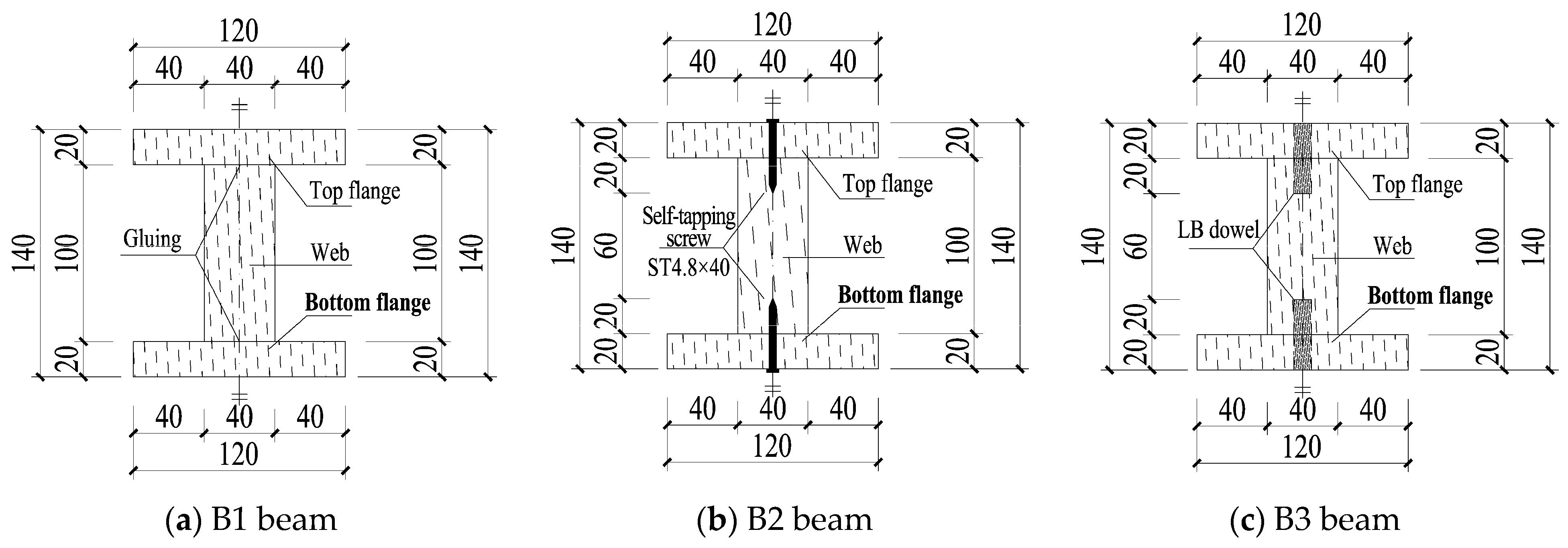
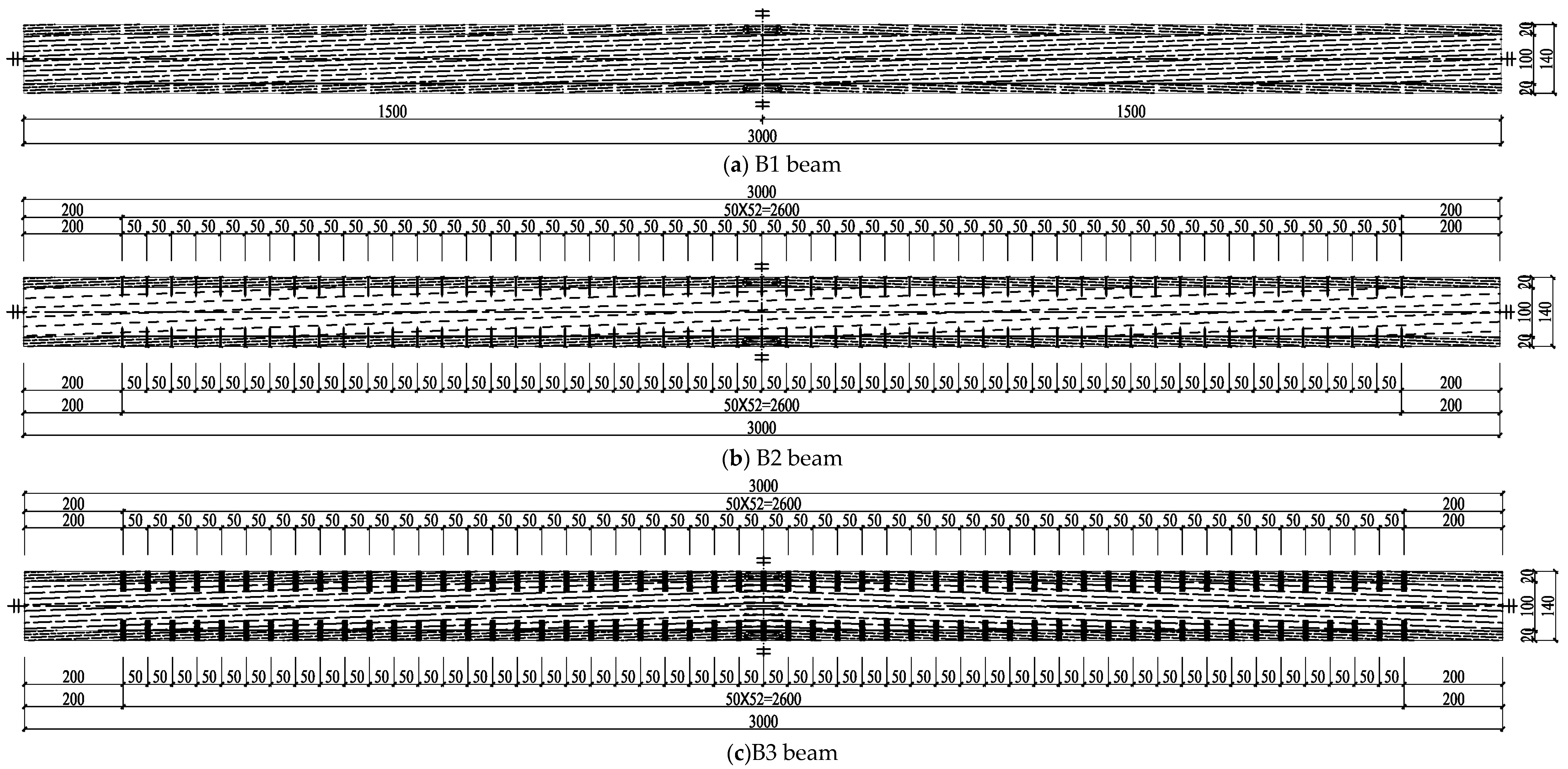
2.2. Specimen Assembly
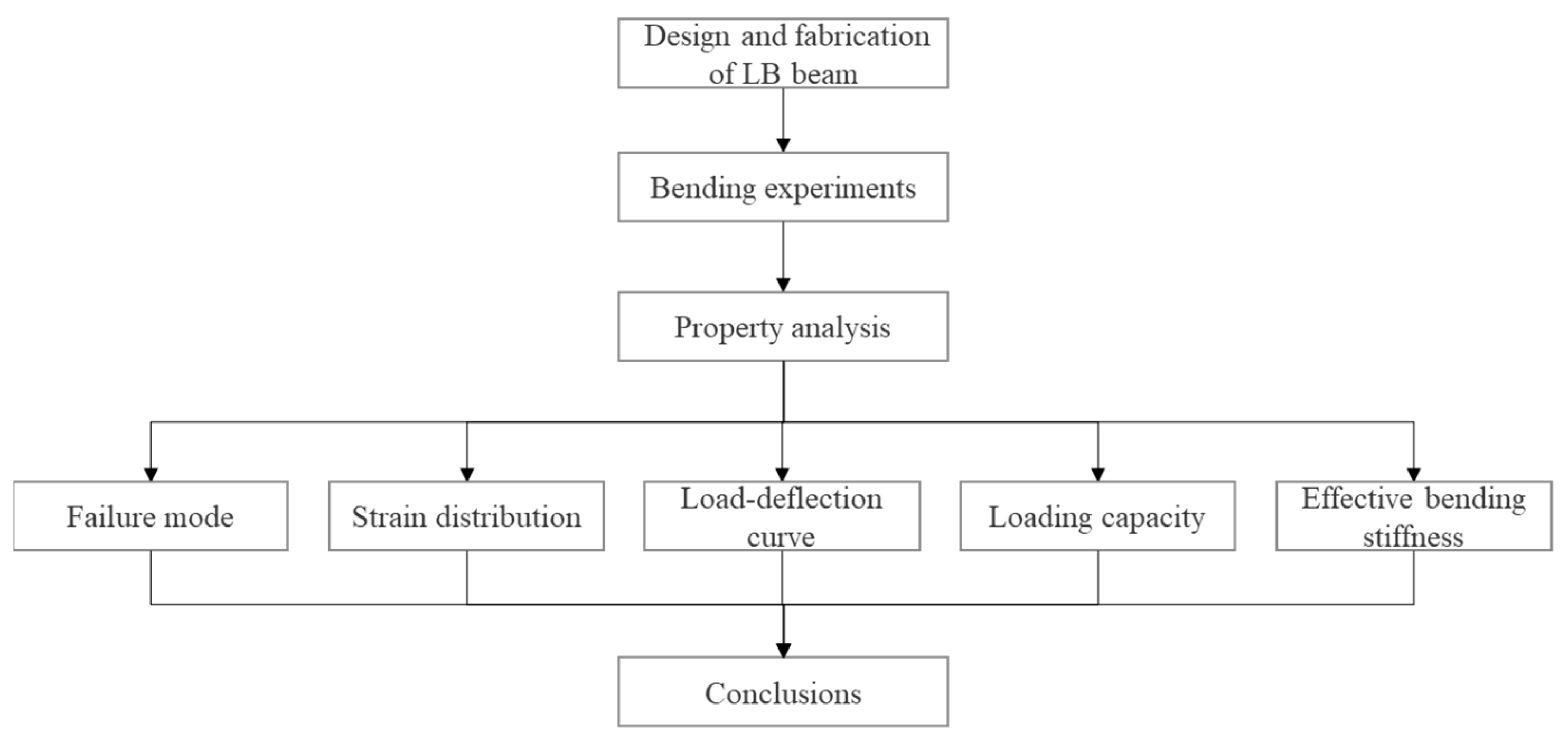
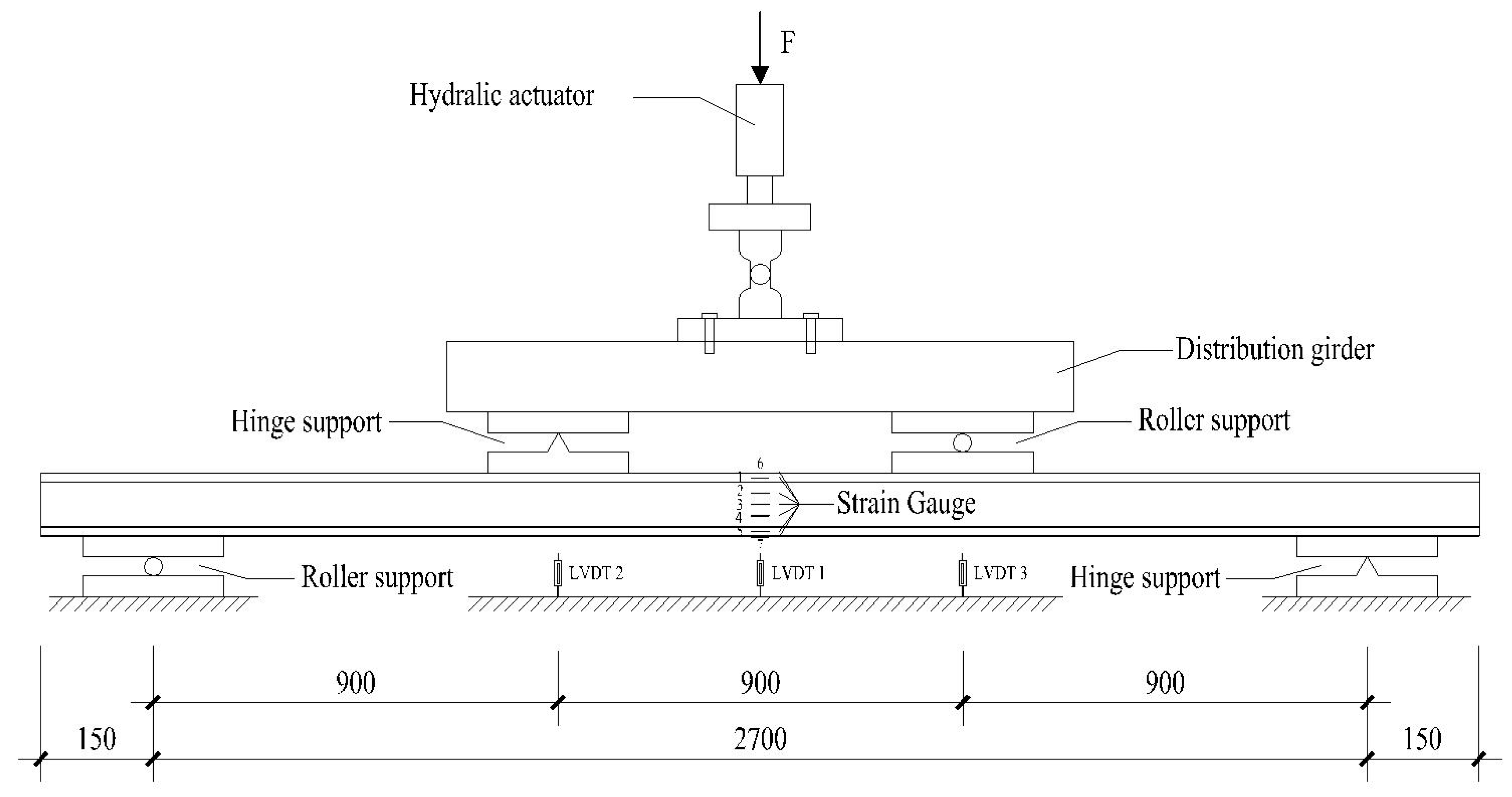
In this study, the components, including webs, top flanges and bottom flanges, were made with LB. The section sizes of the webs were 40 mm by 100 mm, while the top and bottom flanges had dimensions of 120 mm by 20 mm, respectively as shown in Figure 2. As assembling with resin is a normal process, two novel connections of self-screw and LB dowel were employed to investigate the bending properties of composite beams. According to the data presented in Table 2, members with resin, self-screw and LB dowel were marked as B1, B2 and B3 groups, respectively, and for each group, three beams were prepared for testing. Figure 3 shows the dimensions of webs, flanges and fasteners. In the B1 group, the resin used was a phenolic adhesive, which is consistent with the glue used in the manufacturing process, and it was applied to the interface of webs and flanges. The B2 group utilized the ST4.8 mm × 40 mm self-tapping screw, which was implemented with a spacing of 50 mm. In the B3 group, a cylindrical LB dowel with a diameter of 12 mm and a length of 40 mm was utilized with a spacing of 50 mm, which was determined by the embedment and push-out experiments [52]. In the case of groups B2 and B3, it was seen that no glue was utilized on the interface between the webs and flanges, as well as between the connections and reserved holes. Since there was no evidence of microcracks or local delamination in the pertinent literature [53], the drilling procedure was neither used nor taken into consideration. The beams had dimensions of 120 mm in width, 140 mm in height, and 3000 mm in length. The loading span was developed with a length of 2700 mm.

2.3. Test Methods

A four-point bending test was performed using a vertical hydraulic actuator with a maximum load capacity of 500 kN as shown in Figure 4. The test conducted in this study followed the guidelines outlined in ASTM D198 [54], which specified the use of a displacement control mode with a speed of 3 mm/min. There are two situations in which the test should be stopped right away, indicating ultimate failure: (1) when the specimen has obvious damage, such as the bottom flange breaking or the top flange being crushed, when the connectors pull out or shear, or when the component becomes unstable and cannot take any more load; and (2) when the applied load drops quickly and by a lot—more than a certain amount. Before starting loading, one must pre-load and unload two cycles with a force control speed of 2 kN/min within the range of 0.5–2.0 kN to eliminate the gap between the loading device, equipment and specimen, and check whether the instrument works normally.
The static data acquisition equipment TML TDS-530 constantly collected load, strain, and displacement data at a frequency of one measurement per second. Strain gauges were used to quantify the variation and distribution of strain. Two strain gauges were assigned to the surfaces of the top and bottom flanges at the mid-span locations in order to measure the maximum tensile and compressive strains. In the meantime, five gauges were positioned on the lateral side in order to examine the variations occurring across the vertical dimension. One Linear Variable Differential Transformer (LVDT) was positioned at the bottom of the mid-span, while the other two were positioned at two loading sites in order to verify the presence of eccentric loading.

3. Results and Discussion

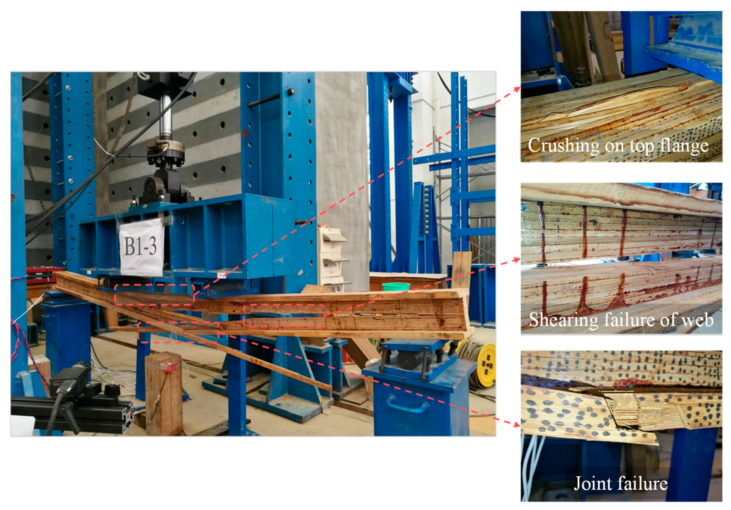
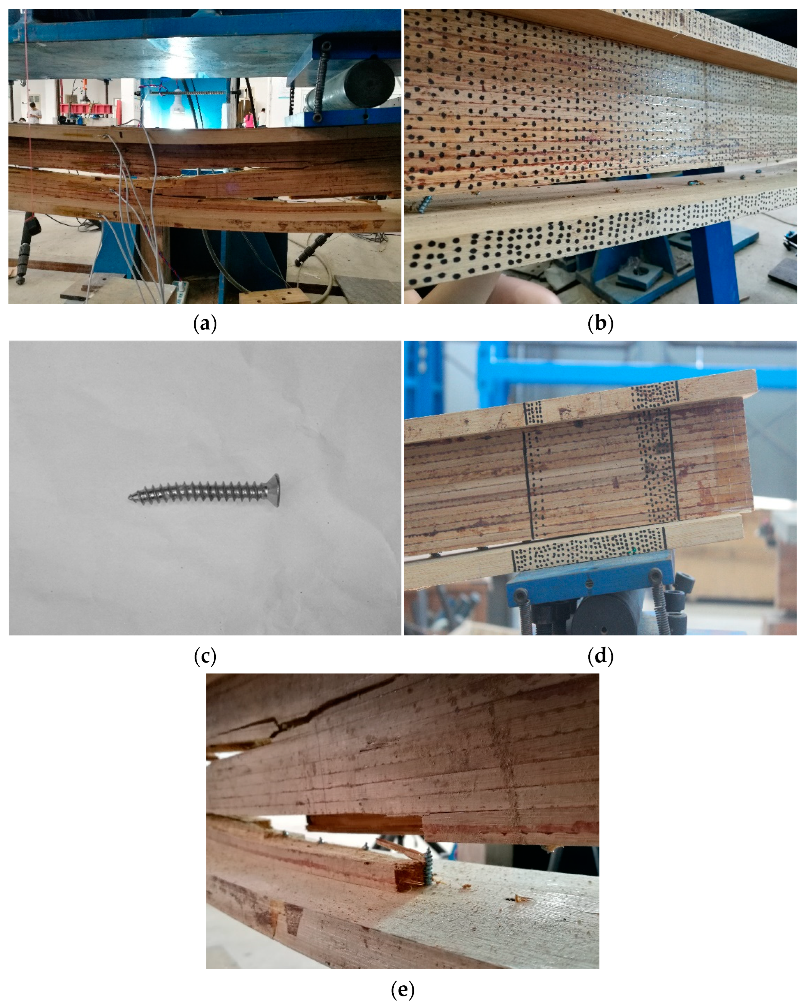
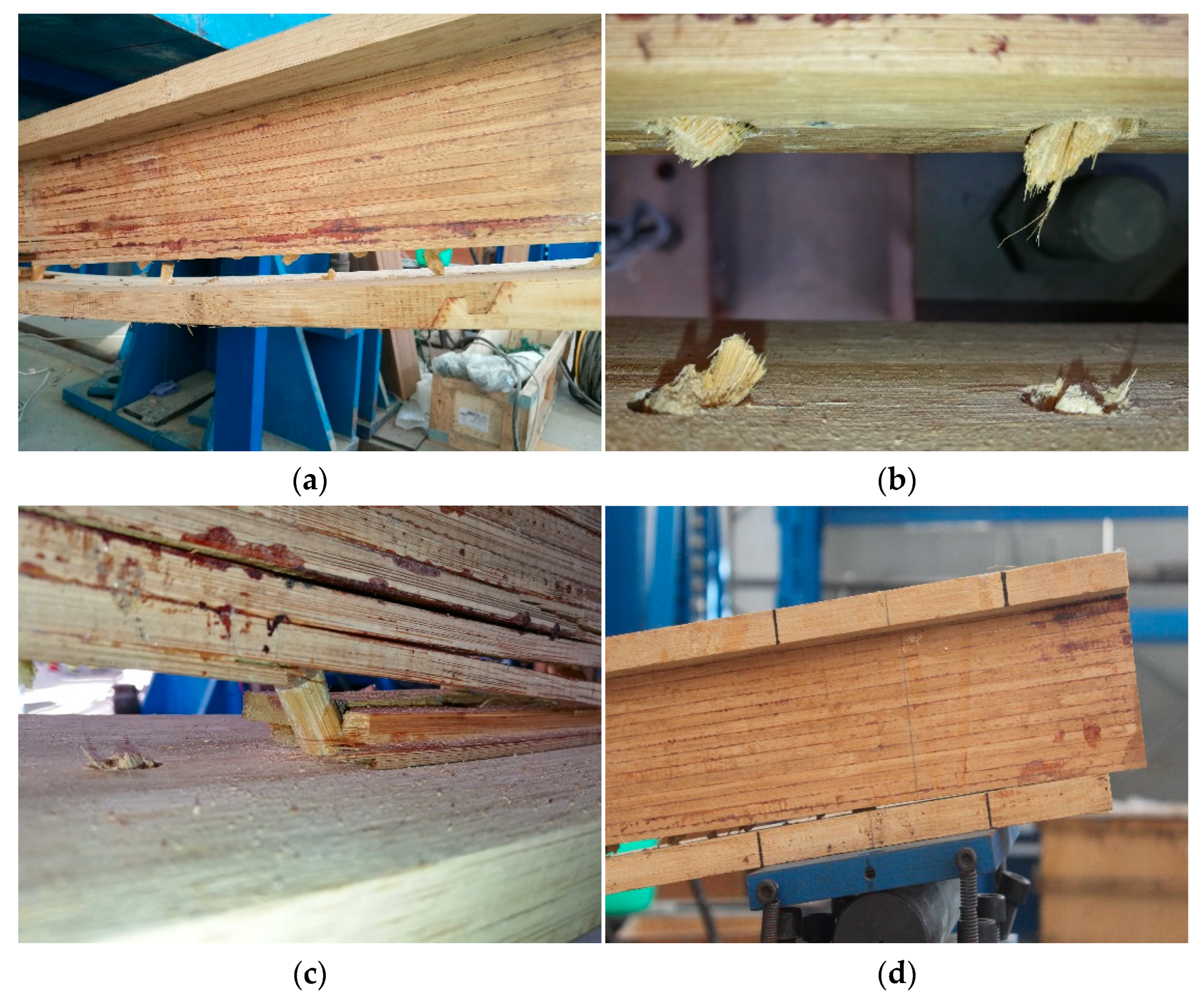
3.1. Observations and Failure Modes

The primary mode of failure observed in the B1 group was tensile fracture, occurring in the lower middle region as shown in Figure 5. This fracture initiation was attributed to the shearing failure of the webs around the loading areas, ultimately resulting in the cracking of fibers. During the elastic stage, the components carried the load jointly, and there was no relative slippage between the web and flange. Once the elastic limit was surpassed, the deformation became increasingly apparent, accompanied by the emergence of longitudinal fractures. These cracks originated in the bamboo matrix and were observed either randomly across the webs or along the integrated bamboo bonding surface with bridging. Upon reaching the ultimate load, the beam exhibited the emergence of several horizontal cracks, resulting in its segmentation into various segments. This phenomenon led to a significant decrease in both load-bearing capacity and stiffness, eventually resulting in a violent collapse characterized by instability. In certain sections, the bamboo joints experienced damage, and the fiber was crushed due to compressive buckling occurring in the top flange. The entirety of the process and the mode of failure exhibited the attributes associated with brittle failure. These findings are consistent with those of previous research [21].
The main failure mode observed in the B2 group was the occurrence of tensile failure in the bottom web, coupled with the failure of the self-tapping screw, as shown in Figure 6a. In the early stages, the utilization of self-tapping screw connections enabled the web and flange to jointly bear the loading. As the load was increased, the bottom screws exhibited significant deformation in the bending and shearing regions, resulting in elevated shearing stress values. Consequently, this increased stress led to shearing damage or pulling out of the screws, as depicted in Figure 6b,c. The occurrence of cracks in the bottom flange can be attributed to the shear action of connections and the resulting relative slip. The lack of a synergistic effect among the different components resulted in a lack of coordination in deformation, which could be recognized by the lines in Figure 6d. Ultimately, the lower flange became completely detached from the component, resulting in a transformation of its original I-shaped configuration into a T-shaped configuration. The failure of the web can be attributed to the combined effects of shear and bending forces, which generated the transverse cracks in the middle and vertical cracks in the bottom, as shown in Figure 6e. These observations are consistent with previous experimental and analytical results for the I-beam [21,43].
As illustrated in Figure 7, the failure modes observed in the B3 group exhibited similarities to those observed in the B2 group, which were mainly caused by the failure of LB dowels. During the initial stage, no visible damage was detected, although a few sounds coming from the connections and beams were perceptible. As the load increased, certain dowels experienced rupture and extraction. However, the beam retained its load-bearing capacity, resulting in a further increase in load following a brief period of decline. When more load was applied, further dowels became detached from the component, resulting in the separation of the bottom flange from the web and uncoordinated deformation. The integrity of the component subsequently deteriorated, leading to tensile failure in the lowest section of the web upon reaching the ultimate load. The parts separated as a result of a shearing failure, rather than a pulling-out failure of dowels, indicating a modest damage process.

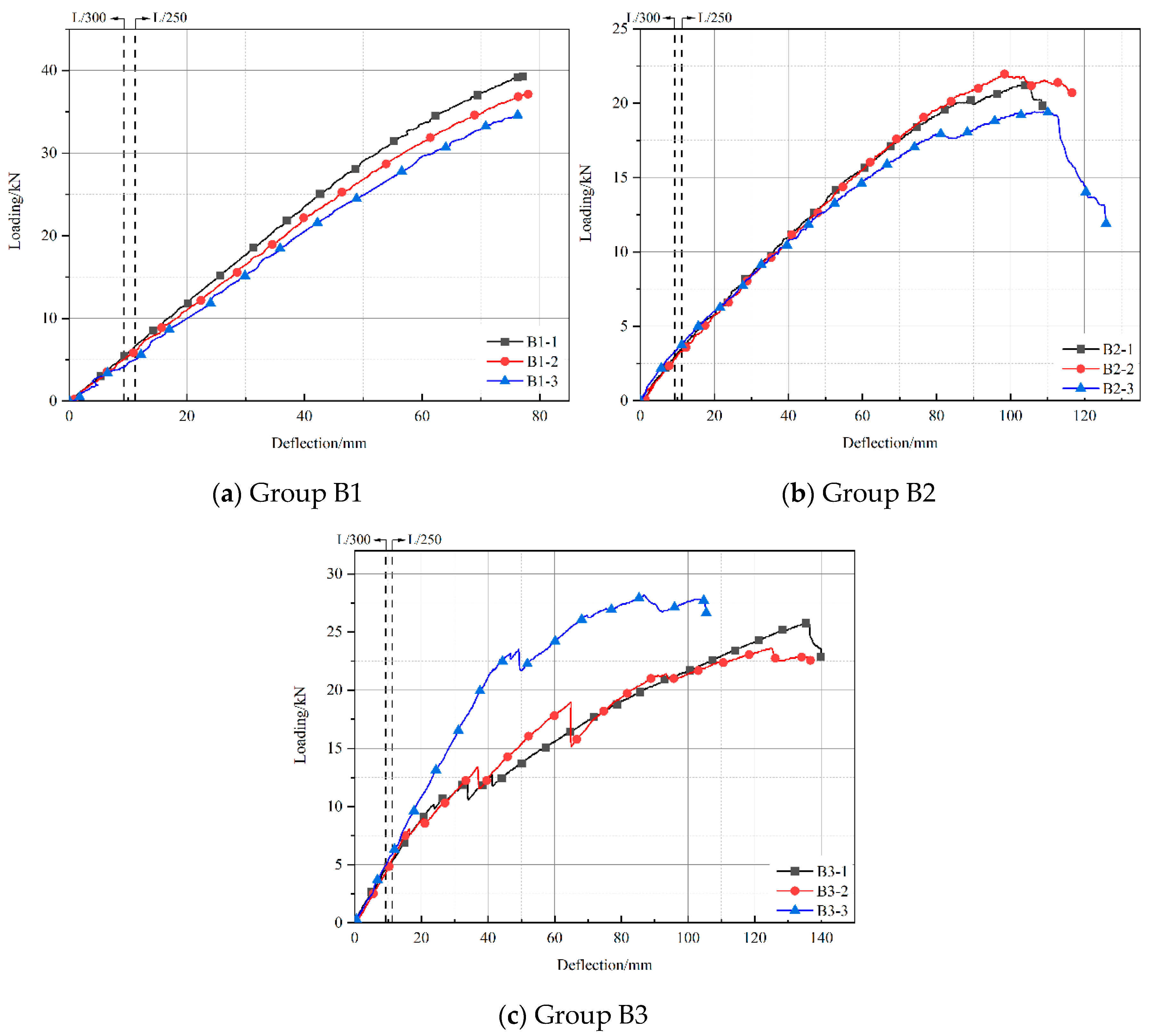
3.2. Load–Deflection Curves

The load–deflection curves for each specimen are presented in Figure 8. In the initial stage, the curves exhibited rapid growth, following a linear trend across all groups. After that, the load increase pattern slowed down for groups B2 and B3. This was due to the slip and failure of connections and the separation of webs and flanges, which made the structure less rigid, and even caused a slight drop for group B3. As the load increased, failure occurred suddenly, and the curves underwent a sharp descent. The curves of the B1 group show a near-linear trend before failure, indicating the exceptional structural integrity achieved by the combination of flange and web components. Based on the B2 group curves, the screw connection exhibits a satisfactory level of reliability and demonstrates a high degree of structural integrity. The curve associated with this connection type generally maintains mostly linear behavior. Moreover, as the point of failure approaches, the curve exhibits limited ductile characteristics. The B3 group curves exhibit a higher prevalence of early failure features in comparison to the other two groups. This is mostly attributed to the relatively lower strength of some LB dowels, which leads to their premature failure. However, ductility, as defined in a related study [55], can also be evaluated based on changes in loading and deflection.
A thorough comparison can result in the determination of three sets of data. Group B1 exhibited the highest ultimate bearing capacity, over 30 kN, while group B3 demonstrated a somewhat lower ultimate bearing capacity, above 22 kN. Among the several groups, group B2 exhibited the lowest bearing capacity, surpassing 18 kN, which is almost two-thirds of the bearing capacity observed in group B1. As a result, composite beams that are bonded with adhesive show the highest level of strength, while those connected using LB dowels demonstrate a slightly lower strength. In comparison to composite components that employ bonding, composite components utilizing self-tapping screws and LB dowels exhibit less stiffness and enhanced ductility.

3.3. Load–Strain Curves

The strains collected from positions 1 to 5 marked in Figure 4 along the height are illustrated in Figure 9 as typical load–strain curves on the lateral side. In order to examine the distribution of strains, a study was conducted using selected moments corresponding to 10%, 20%, 30%, 50%, 70%, 90%, and 100% of the ultimate loading. It is evident that each group exhibits a distinct time during which the strains maintained a linear proportional relationship. Specifically, for beams B1-1, B2-3, and B3-2, this period was characterized by percentages below 70%, 30%, and 50%, respectively. The B1-1 beam maintained a linear connection of over 70%, indicating its ability to remain integral until failure. The strains observed at the interface between the web and flange exhibited a discontinuous pattern once the B2-3 beam load reached 30%. This observation indicates that the flange gradually became detached from the web, resulting in a decrease in the overall structural integrity of the component. Similar observations were made for the B3-2 beam, indicating the need for improvements in the connection performance of both types of connectors. The position of the neutral axis exhibited minimal displacement across all three specimens, indicating that the stress in the tension and compression areas was consistent.
Figure 10 displays the strains that positions 6 and 7 marked in Figure 4 will experience under ideal circumstances. The red and blue points represent bottom flange and top flange ultimate strain, meanwhile two points with same symbol belong to the same beam. The analysis compares these strains with the ultimate strain of LB when tested with uniaxial tension and compression loading. Table 3 presents a comprehensive summary of the ultimate strain endured by each individual specimen. The average ultimate strains of the top flange were found to be −6362 με, −2674 με, and −949 με for groups B1, B2, and B3, respectively. These values are significantly lower than the ultimate compression strain. The average ultimate strains of the bottom flange were measured to be 5771 με, 2701 με, and 1070 με for groups B1, B2, and B3, respectively. The observation suggests that before reaching the point of material failure, individual components separated, and the flanges, particularly those located at the top, had not been fully utilized. The ultimate failure is primarily attributed to the failure of a single component without sufficient connections. In contrast to glued beams, the strains seen in flanges connected with self-tapping screws and LB dowels were found to be lower. This can be attributed to the premature failure of these connections, resulting in increased loads on the web.
The load–strain curves for each beam at the mid-span are presented in Figure 11. It is evident that the upper section of the web and the top flange experienced compressive forces, while the lower section of the web and the bottom flange experienced tensile forces, during the whole bending test. The majority of the curves during the initial loading stage exhibit a linear trend until around 60–70% of the ultimate loading for the B1 group and a lower threshold for the B2 and B3 groups. As the load increased, there was a slight displacement of the neutral axis towards the compression area at position 3. The average strains observed under ultimate loading at position 1 were −5397 με, −2859 με, and −3952 με for the B1, B2, and B3 groups, respectively. These results indicate that significant uncoordinated deformation and separation occurred in the beams with self-tapping screws and LB dowels instead of resin, as compared to position 2, which could also be reflected in Figure 9. In a similar vein, the average strains observed at position 5, namely, 5596 με, 2290 με, and 3057 με for the B1, B2, and B3 groups, respectively, suggest a distinct separation between the web and bottom flange. This means that the web and flange cannot transmit force to each other effectively through the connector at the ultimate moment.

3.4. Flexural Capacity

As presented in Table 4, the capacity, deflection and stiffness of each specimen in the elastic and ultimate stages have been summarized. During the elastic stage, the average proportional limit capacities were 25.99 kN, 13.09 kN and 8.42 kN for groups B1, B2 and B3, which are 70.24%, 62.66% and 32.52% of the ultimate capacity correspondingly. For beams with self-tapping screws and LB dowels, namely, groups B2 and B3, the failure of a few connections affected the rigidity of the beam and prematurely transitioned it into the non-linear stage. The average proportional limit deflections were 61%, 47%, and 15% of the ultimate deflection, or 47.11 mm, 48.31 mm, and 16.54 mm, respectively. The short elastic stage for group B3 was due to the premature failure of the connector. The stiffness values were 0.55 kN/mm, 0.27 kN/mm and 0.52 kN/mm, indicating that before the dowels broke, the rigidity of the LB dowel beam was comparable to that of the glued beam. Enhancing the dowel’s strength could be a useful technique to increase bearing capacity and lessen deflection.
The average ultimate bearing capacities for groups B1, B2, and B3 were 37.00 kN, 20.89 kN, and 25.89 kN in the ultimate limit state, respectively. The differences between the B2 and B3 groups were 43.54% and 30.03%, respectively, as compared to the B1 group. Because the majority of self-tapping screws and LB dowels failed with shearing or pulling out, the beams were divided into various components to withstand the force. The average ultimate deflections were 77.14 mm, 103.66 mm and 115.99 mm for groups B1, B2, and B3, respectively. In comparison to the B1 group, the B2 and B3 groups increased by 34.38% and 50.36%, respectively. The failure loads and deflections of glued beams were almost the same as those of the ultimate stage, while the patterns in self-tapping screw and LB dowel beams were completely the opposite. After the peak point, there was still a ductile segment for both self-tapping screw and LB dowel beams, which could also be observed in Figure 8. The deflections increased from 4.60 mm to 18.50 mm, namely, 4.42% to 18.86%, as the ration in the B2 group increased after the ultimate stage. Meanwhile, the deflections increased from 3.60 mm to 18.80 mm, namely, 2.64% to 21.45%, with the increasing ratio in the B3 group. Thus, group B2 and B3 showed ductility and early warnings of damage. This is similar to the conclusion obtained in previous studies [49], finding that steel dowels increase the ductility and reduce the stiffness.
Some standards and codes prescribe a deflection limit value under the serviceability limit state to maintain safety, which, in GB 50005 [56], is L/250, and in EC5 [57] is L/300, where L is the span of the beam. Based on this, the results are listed in Table 5, and Fs/Fu is a reflection of the degree of exertion of the materials. Although the serviceability limits of groups B2 and B3 were lower than those of group B1, the ratio of Fs to Fu was higher, which could show that the LB dowel and self-tapping screw were still potentially viable connection approaches.

3.5. Application of the Gamma Method

According to EC5 part 1-1, the effective bending stiffness calculated by the Gamma method can be expressed as:
E I e f = i = 1 3 E i I i + γ i E i A i a i 2
where E i , I i and A i are the longitudinal elastic modulus, section moment of inertia and cross-section area, respectively. a i is the distance between the centroids of the flange or web, determined relative to the neutral axis, and can be calculated as follows:
a 1 = h 1 + h 2 2 + a 2
a 3 = h 2 + h 3 2 + a 2
a 2 = γ 1 E 1 A 1 h 1 + h 2 γ 3 E 3 A 3 h 2 + h 3 2 i = 1 3 γ i E i A i
where h i is the height of the flange or web. γ i is the connection efficiency factor and can be defined as:
γ i = 1 + π 2 E i A i s i / K i L 2 1
where s i , K i and L are the spacing of the self-tapping screws or LB dowels, the slip modulus and the loading span, respectively. For group B1, γ i equals 1. Since the slip modulus of self-tapping screws or LB dowels within LB members has not been reported previously, a method for estimating K i is applied, derived from EC5, which can be expressed as:
K i = ρ m 1.5 d / 23
where ρ m is the mean density of LB (0.57 g/cm3) and d is the diameter of the self-tapping screws or LB dowels.
The experimental effective bending stiffness is calculated with
E I e f , exp = 3 L 2 4 a 2 48 Δ P Δ y a
where a is the loading span. Table 6 lists the experimental and model predictions of effective bending stiffness. Apparently, the effective bending stiffness of group B1 is larger than that of the other two groups, since the connection failure of screws and dowels occurred earlier. The errors calculated with a deformation limit of L/250 are smaller than those of the other two limits, thus the earlier limit could be adopted to provide higher accuracy. The results indicate that the Gamma method is still not applicable for LB composite beams, as too much slip could influence the outcomes and necessitate further research.

4. Conclusions

Experimental and analytical research using glued, self-tapping screws and innovative LB dowel beams is presented in this paper. Investigations on loading behavior and bending performance demonstrate the potential of LB dowels. Failure mechanisms, load–deflection curves, load–strain relationships, and properties including stiffness and capacity are examined. The following are the key conclusions:
  • The primary failure mode for three groups was the tensile fracture in the bottom of the web, which resulted from the separation of the flange from the web and the failure of connections under high stress. Before the elastic proportional limit, groups B2 and B3 showed little indication of relative slip, and the slip gradually increased when close to the ultimate limit. The load-deflection curves and failure mode showed ductile behavior, while the beams with self-tapping screws and LB dowels lost their capacity and stiffness quickly after the connectors broke, which could be reflected by their lower ultimate capacity and higher deflection, correspondingly;
  • The load–deflection curves of group B2 and B3 demonstrate a nonlinear stage, while group B1 showed a near-linear trend before the peak point. The premature drop of the curve means the premature failure of the LB dowel in group B3, which caused the early end of the elastic stage. After the ultimate limit, group B1 failed rapidly, meanwhile group B2 and B3 showed some signs and some ductility;
  • The capacity and deflection of group B1 were obviously higher (77.12% and 42.91% more than group B2 and B3, respectively) and lower (25.58% and 33.49% less than group B2 and B3) than those of the other two groups, which means gluing is still a highly efficient connecting method, although there are disadvantage related to sudden brittle failure. The deflection continued to increase 12.88% and 11.16% on average for group B2 and B3, respectively, after the peak point, indicating the destruction was a relatively slow process compared with group B1;
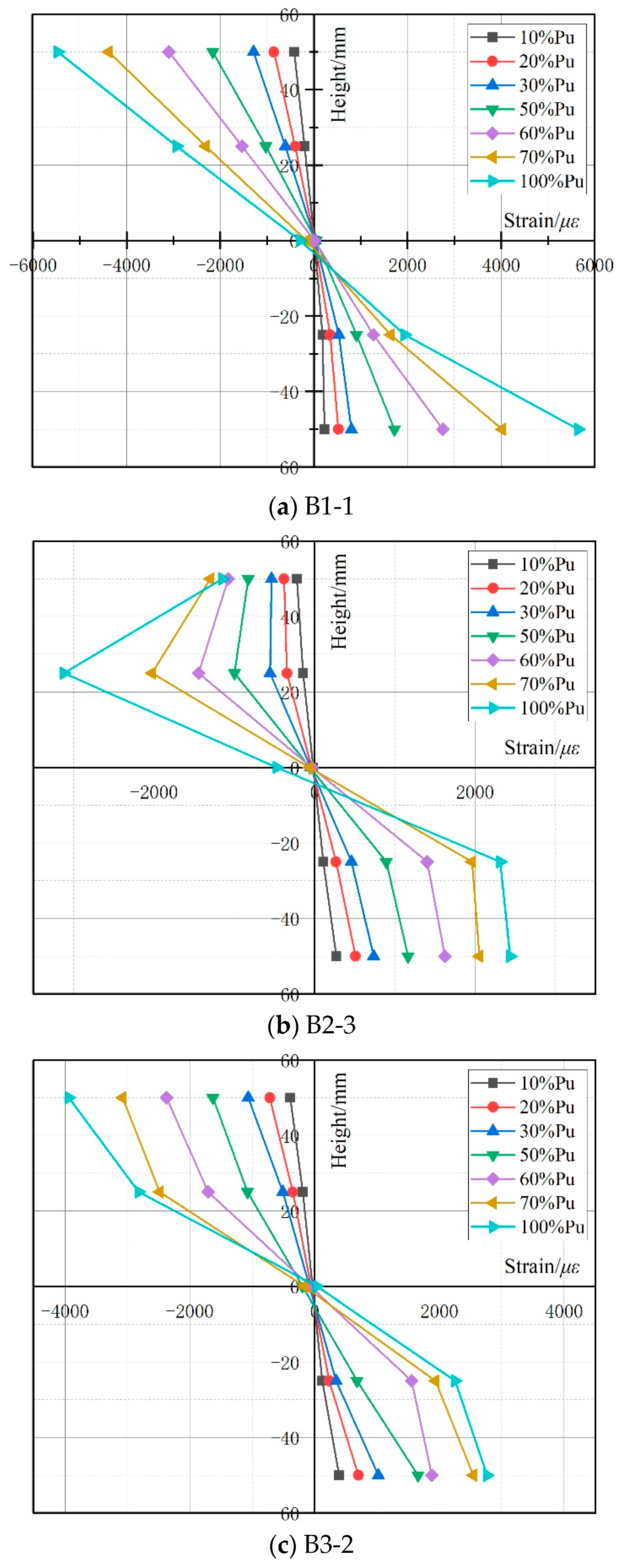
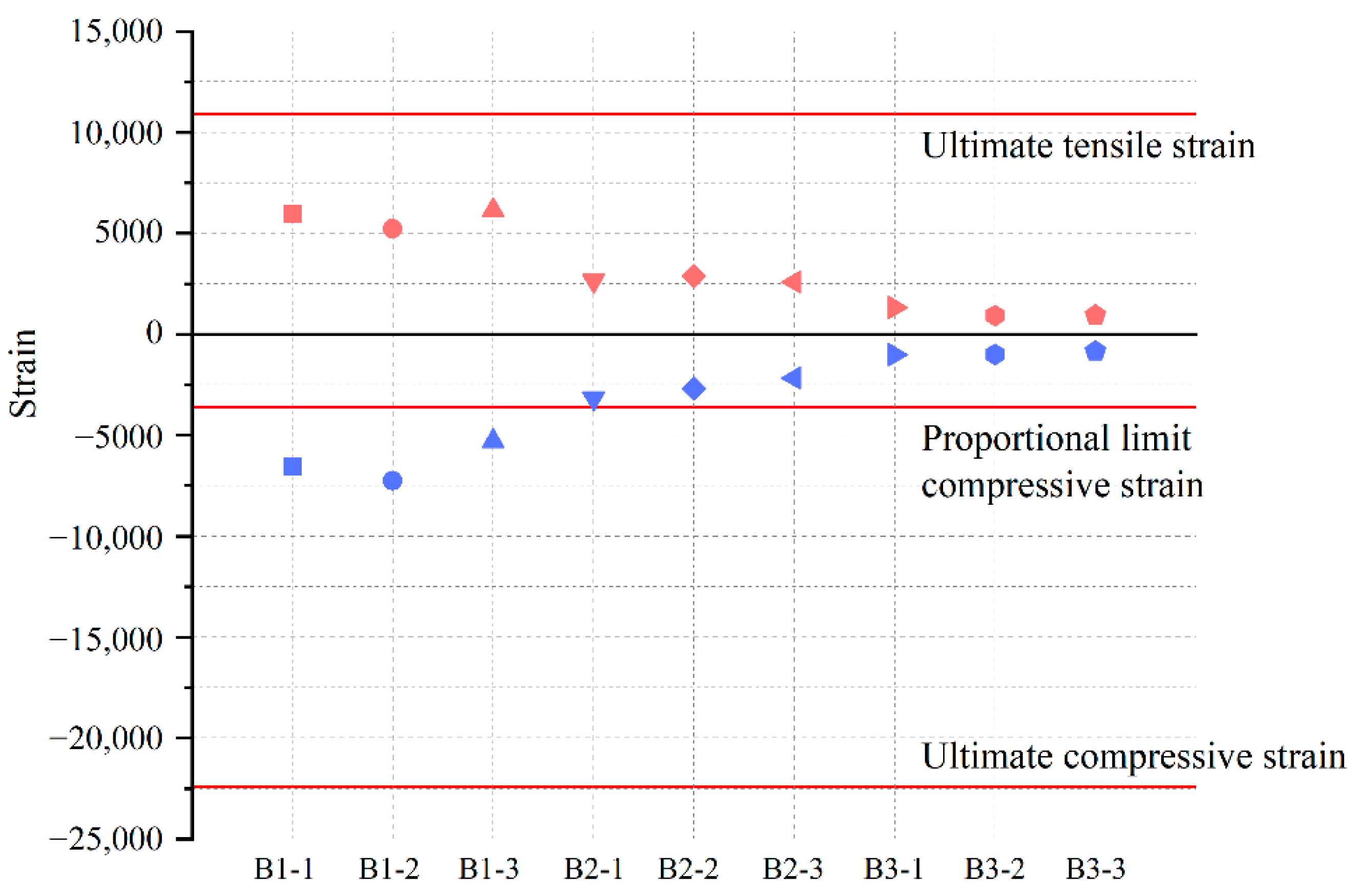
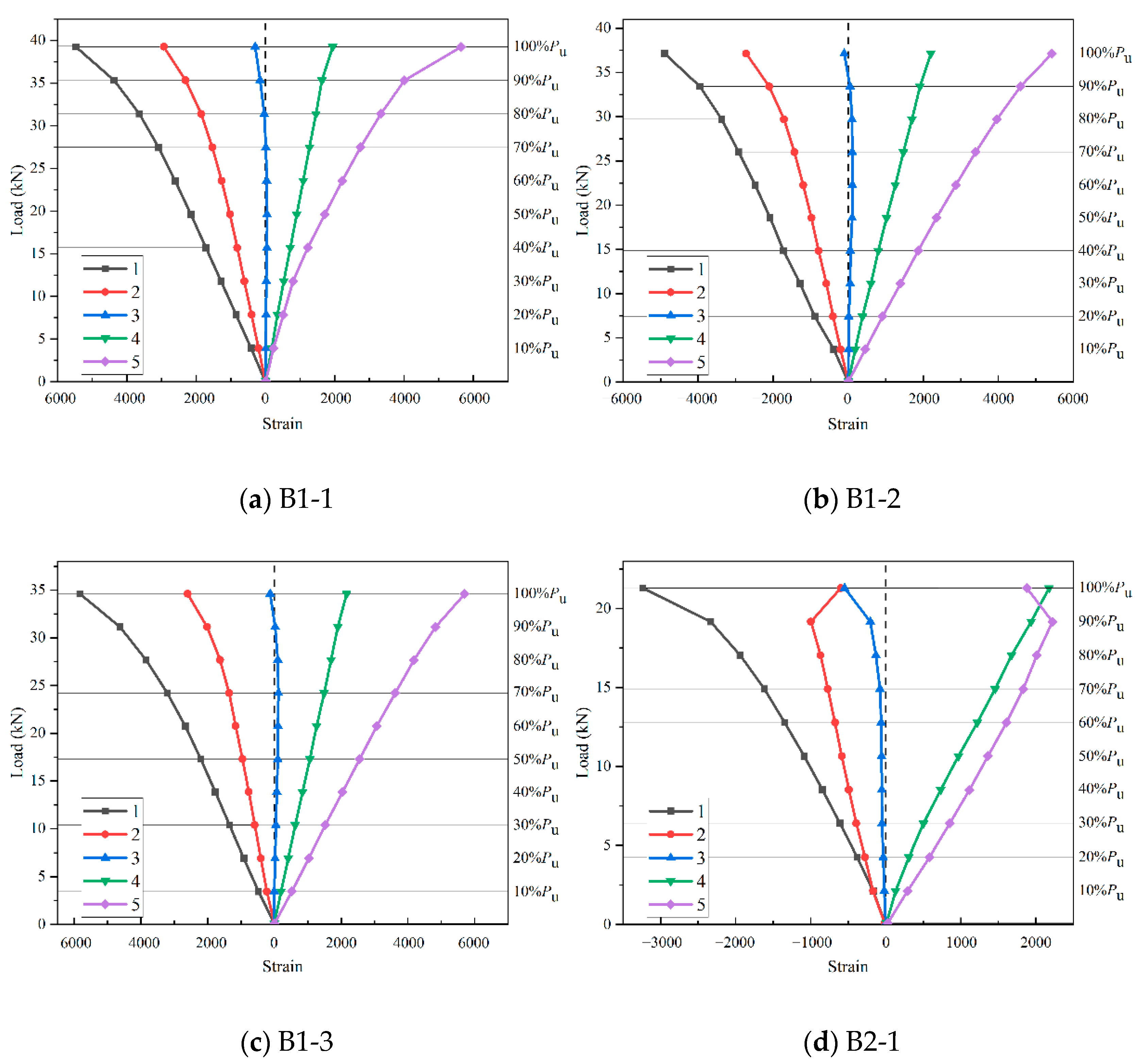
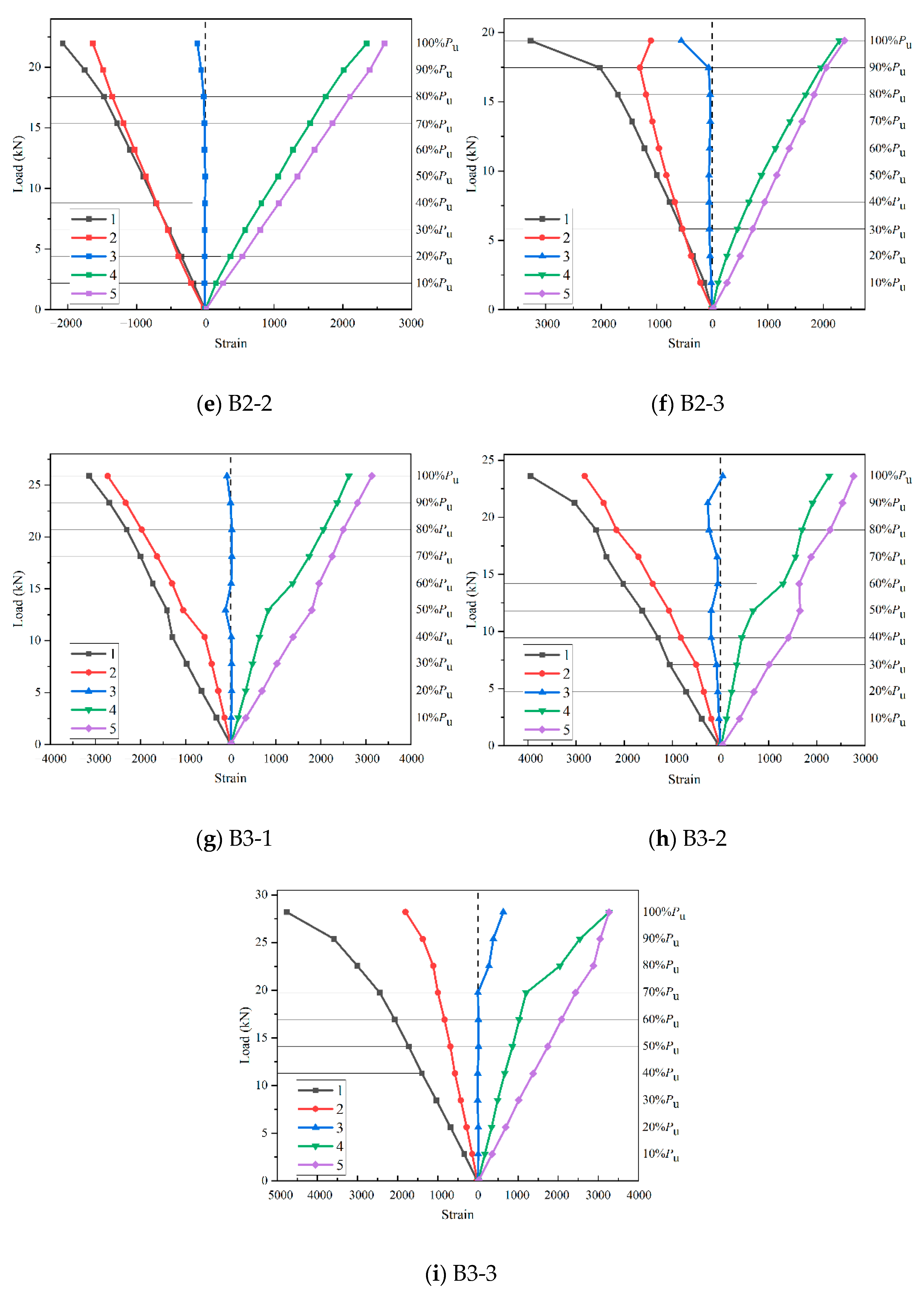
  • At a low stress level, strains distributed linearly along the height, but the strain distribution became nonlinear at middle to high stress levels, demonstrating the uncoordinated deformation of the web and flange and the occurrence of separation. The ultimate strains of the top and bottom flanges were only 3.76–32.33% and 8.52–56.28% of the ultimate strain under uniaxial compression and tension loading, respectively. This means the failure occurred more because of the connection and component aspects rather than the material aspects. Thus, strengthening the connection and components through the utilization of FRP or concrete could make better use of material;
  • The Gamma method from EC5 was used to estimate the effective bending stiffness. The calculation achieved good agreement, with the test results were within the L/250 and L/300 limits, but the errors are larger than others within the elastic proportional limit since there were too many slips.
The load–deflection curves, strain distributions, capacities and deflections obtained from experimental and analytical research show the possibility of utilizing LB dowels in place of gluing. Furthermore, this option was enhanced by the benefits of environmental sustainability and a decreased chance of embedment failure. However, issues such as shearing and pulling-out failure should be solved first, and research on connector dimensions, interface slips, nonlinear properties and calculation models should be considered.

Author Contributions

J.L.: conceptualization, writing—original draft, writing—review and editing, funding acquisition. A.S.: conceptualization, methodology, investigation, writing—original draft, writing—review and editing, funding acquisition. Y.Z.: conceptualization, methodology, investigation, funding acquisition. All authors have read and agreed to the published version of the manuscript.

Funding

This research was funded by the National Natural Science Foundation of China (No. 52178109), the Natural Science Foundation of Jiangsu Educational Department (No. 21KJD560004); Changzhou Sci & Tech Program (No. CQ20234019, No. CJ20210132).

Data Availability Statement

The data presented in this study are available on request from the corresponding author. The data are not publicly available due to privacy.

Conflicts of Interest

The authors declare that they have no known competing financial interests or personal relationships that could have influenced the work reported in this paper.

References

  1. Harries, K.A. Material characterisation of bamboo for glued-laminated products. Adv. Bamboo Sci. 2023, 3, 100023. [Google Scholar] [CrossRef]
  2. Bhagat, D.; Bhalla, S.; West, R.P. Fabrication and structural evaluation of fibre reinforced bamboo composite beams as green structural elements. Compos. Part C Open Access 2021, 5, 100150. [Google Scholar] [CrossRef]
  3. Liu, Y.; Zhang, J.; Xu, J.; Wang, Y.; Li, B.; Zhang, S. Carbon emission-based life cycle assessment of rural residential buildings constructed with engineering bamboo: A case study in China. J. Build. Eng. 2023, 76, 107182. [Google Scholar] [CrossRef]
  4. Du, J.; Yang, K.-L.; Yuan, Z.-Q.; Liu, Z.-M.; Li, X.-Y.; Liu, S.-J.; Li, C.-C.; Meng, S.-T.; Wu, R.-M. Effect of physical treatment methods on the properties of natural bamboo materials. Constr. Build. Mater. 2023, 394, 132170. [Google Scholar] [CrossRef]
  5. Hartono, R.; Iswanto, A.H.; Priadi, T.; Herawati, E.; Farizky, F.; Sutiawan, J.; Sumardi, I. Physical, Chemical, and Mechanical Properties of Six Bamboo from Sumatera Island Indonesia and Its Potential Applications for Composite Materials. Polymers 2022, 14, 4868. [Google Scholar] [CrossRef]
  6. Gan, J.; Chen, M.; Semple, K.; Liu, X.; Dai, C.; Tu, Q. Life cycle assessment of bamboo products: Review and harmonization. Sci. Total Environ. 2022, 849, 157937. [Google Scholar] [CrossRef]
  7. Qiu, Z.; Wang, J.; Fan, H. Impact bending behaviors of parallel bamboo strand lumber beams: Velocity sensitivity and anisotropy. Compos. Struct. 2021, 263, 113711. [Google Scholar] [CrossRef]
  8. Hong, C.; Li, H.; Lorenzo, R.; Wu, G.; Corbi, I.; Corbi, O.; Xiong, Z.; Yang, D.; Zhang, H. Review on connections for original bamboo structures. J. Renew. Mater. 2019, 7, 714–730. [Google Scholar] [CrossRef]
  9. Sun, X.; He, M.; Li, Z. Novel engineered wood and bamboo composites for structural applications: State-of-art of manufacturing technology and mechanical performance evaluation. Constr. Build. Mater. 2020, 249, 118751. [Google Scholar] [CrossRef]
  10. Tang, S.; Zhou, A.; Li, J. Mechanical Properties and Strength Grading of Engineered Bamboo Composites in China. Adv. Civ. Eng. 2021, 2021, 6666059. [Google Scholar] [CrossRef]
  11. Chen, G.; Yu, Y.; Li, X.; He, B. Mechanical behavior of laminated bamboo lumber for structural application: An experimental investigation. Eur. J. Wood Wood Prod. 2020, 78, 53–63. [Google Scholar] [CrossRef]
  12. Dauletbek, A.; Li, H.; Xiong, Z.; Lorenzo, R. A review of mechanical behavior of structural laminated bamboo lumber. Sustain. Struct. 2021, 1, 116898. [Google Scholar] [CrossRef]
  13. Nkeuwa, W.N.; Zhang, J.; Semple, K.E.; Chen, M.; Xia, Y.; Dai, C. Bamboo-based composites: A review on fundamentals and processes of bamboo bonding. Compos. B Eng. 2022, 235, 109776. [Google Scholar] [CrossRef]
  14. Yuan, T.; Wang, X.; Liu, X.; Lou, Z.; Mao, S.; Li, Y. Bamboo flattening technology enables efficient and value-added utilization of bamboo in the manufacture of furniture and engineered composites. Compos. B Eng. 2022, 242, 110097. [Google Scholar] [CrossRef]
  15. Li, H.T.; Chen, G.; Zhang, Q.; Ashraf, M.; Xu, B.; Li, Y. Mechanical properties of laminated bamboo lumber column under radial eccentric compression. Constr. Build. Mater. 2016, 121, 644–652. [Google Scholar] [CrossRef]
  16. Huang, Z.; Chen, Z.; Huang, D.; Zhou, A. The ultimate load-carrying capacity and deformation of laminated bamboo hollow decks: Experimental investigation and inelastic analysis. Constr. Build. Mater. 2016, 117, 190–197. [Google Scholar] [CrossRef]
  17. Qiu, Z.; Wang, J.; Jin, F.; Fan, H. Construction and structural performances of laminated bamboo arches. Compos. Struct. 2021, 266, 113799. [Google Scholar] [CrossRef]
  18. Li, H.T.; Liu, R.; Lorenzo, R.; Wu, G.; Wang, L.-B. Eccentric compression properties of laminated bamboo columns with different slenderness ratios. Proc. Inst. Civ. Eng. Struct. Build. 2019, 172, 315–326. [Google Scholar] [CrossRef]
  19. Li, H.; Chen, B.; Fei, B.; Li, H.; Xiong, Z.; Lorenzo, R.; Fang, C.; Ashraf, M. Mechanical properties of aramid fiber reinforced polymer confined laminated bamboo lumber column under cyclic loading. Eur. J. Wood Wood Prod. 2022, 80, 1057–1070. [Google Scholar] [CrossRef]
  20. Xu, J.J.; Xiong, W.W.; Wang, X.; Li, Z.; Xiao, Y.; Qin, S.J. Experimental investigation on shear behavior of full-scale glued laminated bamboo beams under three-point loading test and using digital image correlation technique. Ind. Crops Prod. 2023, 204, 117391. [Google Scholar] [CrossRef]
  21. Chen, S.; Wei, Y.; Zhao, K.; Dong, F.; Huang, L. Experimental investigation on the flexural behavior of laminated bamboo-timber I-beams. J. Build. Eng. 2022, 46, 103651. [Google Scholar] [CrossRef]
  22. Li, H.; Wu, G.; Zhang, Q.; Deeks, A.J.; Su, J. Ultimate bending capacity evaluation of laminated bamboo lumber beams. Constr. Build. Mater. 2018, 160, 365–375. [Google Scholar] [CrossRef]
  23. Penellum, M.; Sharma, B.; Shah, D.U.; Foster, R.M.; Ramage, M.H. Relationship of structure and stiffness in laminated bamboo composites. Constr. Build. Mater. 2018, 165, 241–246. [Google Scholar] [CrossRef]
  24. Lei, J.; Chen, B.; Yuan, P. Experimental Study on Flexural Properties of Side-Pressure Laminated Bamboo Beams. Adv. Civ. Eng. 2020, 2020, 5629635. [Google Scholar] [CrossRef]
  25. Tesfaye Deresa, S.; Xu, J.; Shan, B.; Ren, H.; Xiao, Y. Experimental investigation on flexural behavior of full-scale glued laminated bamboo (glubam)-concrete composite beams: A case study of using recycled concrete aggregates. Eng. Struct. 2021, 233, 111896. [Google Scholar] [CrossRef]
  26. Deng, Y.; Hao, Y.; Mohamed, A.; Wong, S.H.; Tang, Y.; Yuen, T.Y.; Sukontasukkul, P.; Shen, M.; Fernando, N.; Saint, R.; et al. Experimental investigation of mechanically laminated straight or curved-and-tapered bamboo-concrete T-beams. Eng. Struct. 2023, 283, 115896. [Google Scholar] [CrossRef]
  27. Shan, B.; Wang, Z.Y.; Li, T.Y.; Xiao, Y. Experimental and Analytical Investigations on Short-Term Behavior of Glubam-Concrete Composite Beams. J. Struct. Eng. 2020, 146, 106–117. [Google Scholar] [CrossRef]
  28. Wang, Z.; Wei, Y.; Hu, Y.; Chen, S.; Zhao, K. An investigation of the flexural performance of bamboo-concrete composite beams with precast light concrete slabs and dowel connectors. J. Build. Eng. 2021, 41, 102759. [Google Scholar] [CrossRef]
  29. Xu, J.J.; Xiong, W.W.; Shan, B.; Wen, J.; Xiao, Y. Bending stiffness of bamboo-concrete composite (BCC) beams under short-term loads. J. Build. Eng. 2022, 60, 105170. [Google Scholar] [CrossRef]
  30. Lv, Q.; Ding, Y.; Liu, Y. Effect of the Nonprestressed/Prestressed BFRP Bar on Flexural Performance of the Bamboo Beam. Adv. Polym. Technol. 2019, 2019, 7143023. [Google Scholar] [CrossRef]
  31. Yang, Y.; Fahmy, M.F.; Pan, Z.; Zhan, Y.; Wang, R.; Wang, B.; Feng, B. Experimental study on basic mechanical properties of new BFRP-bamboo sandwich structure. Constr. Build. Mater. 2020, 264, 120642. [Google Scholar] [CrossRef]
  32. Wang, Z.; Li, H.; Fei, B.; Ashraf, M.; Xiong, Z.; Lorenzo, R.; Fang, C. Axial compressive performance of laminated bamboo column with aramid fiber reinforced polymer. Compos. Struct. 2021, 258, 113398. [Google Scholar] [CrossRef]
  33. Tian, Y.; Li, H.; Chen, B.; Lorenzo, R.; Ashraf, M. Experimental and theoretical investigation of prestressed-steel-reinforced laminated bamboo lumber beams. Structures 2023, 47, 434–448. [Google Scholar] [CrossRef]
  34. Ding, J.; Wang, X.; Ge, Y.; Zhang, Z.; Li, Y. Experimental study and theoretical analysis of the shear behavior of single-box double-chamber steel-bamboo composite beams. Eng. Struct. 2023, 296, 116959. [Google Scholar] [CrossRef]
  35. Wu, F.; Wei, Y.; Lin, Y.; Zhao, K.; Huang, L. Experimental study of bamboo scrimber-filled steel tube columns under axial compression. Eng. Struct. 2023, 280, 115669. [Google Scholar] [CrossRef]
  36. Ding, J.; Wang, X.; Ge, Y.; Zhang, J.; Shan, Q.; Xu, S.; Wang, J.; Li, Y. Experimental and nonlinear analytical investigation of the flexural performance of single-box double-chamber steel–bamboo composite beams. Thin-Walled Struct. 2023, 183, 110424. [Google Scholar] [CrossRef]
  37. Li, L.; Huang, C.; Guo, N. Flexural behaviour of bamboo scrimber beams with different composite and reinforced technology: A literature review. Case Stud. Constr. Mater. 2024, 20, e02805. [Google Scholar] [CrossRef]
  38. Chen, G.; Wu, J.; Jiang, H.; Zhou, T.; Li, X.; Yu, Y. Evaluation of OSB webbed laminated bamboo lumber box-shaped joists with a circular web hole. J. Build. Eng. 2020, 29, 101129. [Google Scholar] [CrossRef]
  39. Zhang, Z.; Qiu, Z. Experimental study on bending properties of bamboo-wood composite beams with different tectonic patterns. Polym. Test 2023, 118, 107907. [Google Scholar] [CrossRef]
  40. Zhang, H.; Shen, M.; Deng, Y.; Andras, P.; Sukontasukkul, P.; Yuen, T.Y.; Tang, Y.; Wong, S.H.; Limkatanyu, S.; Singleton, I.; et al. A new concept of bio-based prestress technology with experimental Proof-of-Concept on Bamboo-Timber composite beams. Constr. Build. Mater. 2023, 402, 132991. [Google Scholar] [CrossRef]
  41. Wang, Z.; Wei, Y.; Li, N.; Zhao, K.; Ding, M. Flexural behavior of bamboo–concrete composite beams with perforated steel plate connections. J. Wood Sci. 2020, 66, 4. [Google Scholar] [CrossRef]
  42. Otero-Chans, D.; Estévez-Cimadevila, J.; Suárez-Riestra, F.; Martín-Gutiérrez, E. Experimental analysis of glued-in steel plates used as shear connectors in Timber-Concrete-Composites. Eng. Struct. 2018, 170, 1–10. [Google Scholar] [CrossRef]
  43. Wang, M.; Zhao, Y.; Xu, Q.; Harries, K.A.; Li, X.; Leng, Y. Experimental research on wood beams strengthened with engineered bamboo laminates attached with self-tapping screws. J. Build. Eng. 2022, 53, 104560. [Google Scholar] [CrossRef]
  44. Wang, S.; Li, H.; Cheng, G.; Xiong, Z.; Ashraf, M. Mechanical behavior of bolted steel laminated bamboo lumber connections loaded perpendicular to grain. Constr. Build. Mater. 2022, 345, 128302. [Google Scholar] [CrossRef]
  45. Jiang, Y.; Crocetti, R. CLT-concrete composite floors with notched shear connectors. Constr. Build. Mater. 2019, 195, 127–139. [Google Scholar] [CrossRef]
  46. Martín-Gutiérrez, E.; Estévez-Cimadevila, J.; Otero-Chans, D.; Suárez-Riestra, F. Discontinuous π-form steel shear connectors in timber-concrete composites. An experimental approach. Eng. Struct. 2020, 216, 110719. [Google Scholar] [CrossRef]
  47. Sebastian, W.M.; Piazza, M.; Harvey, T.; Webster, T. Forward and Reverse shear transfer in beech LVL-concrete composites with singly inclined coach screw connectors. Eng. Struct. 2018, 175, 231–244. [Google Scholar] [CrossRef]
  48. Ling, Z.; Zhang, H.; Mu, Q.; Xiang, Z.; Zhang, L.; Zheng, W. Shear performance of assembled shear connectors for timber–concrete composite beams. Constr. Build. Mater. 2022, 329, 127158. [Google Scholar] [CrossRef]
  49. Li, H.; Wei, Y.; Yan, L.; Semple, K.E.; Dai, C. Structural behavior of steel dowel-reinforced cross-laminated bamboo and timber beams. Compos. Struct. 2023, 318, 117111. [Google Scholar] [CrossRef]
  50. Chen, S.; Wei, Y.; Zhu, J.; Lin, Y.; Du, H. Experimental investigation of the shear performance of bamboo scrimber beams reinforced with bamboo pins. Constr. Build. Mater. 2023, 365, 130044. [Google Scholar] [CrossRef]
  51. ASTM D143-14; Standard Test Methods for Small Clear Specimens of Timber. American Society of Mechanical Engineers: New York City, NY, USA, 2014.
  52. Li, J.; Zhou, A. Mechanical behavior of laminated bamboo lumber dowel-type connection. Adv. Struct. Eng. 2020, 23, 65–73. [Google Scholar] [CrossRef]
  53. Leng, Y.; Xu, Q.; Wang, M.; Guo, H.; Harries, K.A.; Chen, L. Experimental study of withdrawal behavior of self-tapping screws in laminated bamboo. Constr. Build. Mater. 2023, 363, 129890. [Google Scholar] [CrossRef]
  54. ASTM D198-15; Standard Test Methods of Static Tests of Lumber in Structural Sizes. American Society of Mechanical Engineers: New York City, NY, USA, 2015.
  55. Zhu, W.; Yang, H.; Liu, W.; Shi, B.; Ling, Z.; Tao, H. Experimental investigation on innovative connections for timber–concrete composite systems. Constr. Build. Mater. 2019, 207, 345–356. [Google Scholar] [CrossRef]
  56. GB 50005; Standard for Design of Timber Structures. China Architecture & Building Press: Beijing, China, 2017.
  57. EN 1995-1-1:2004; Eurocode 5: Design of Timber Structures—Part 1.1: General-Common Rules and Rules for Buildings. European Standards Organization: Brussels, Belgium, 2004.
Figure 1. Flow diagram of research.
Buildings 14 00671 g001
Figure 2. Section view of beams.
Buildings 14 00671 g002
Figure 3. Details of test specimens.
Buildings 14 00671 g003
Figure 4. Test set-up (unit: mm).
Buildings 14 00671 g004
Figure 5. Failure mode of B1 beam.
Buildings 14 00671 g005
Figure 6. Failure mode of B2 beam. (a) Typical failure mode; (b) Separation of web and bottom flange; (c) Screw bending; (d) Relative slip; (e) Tensile fracture in bottom of web.
Buildings 14 00671 g006
Figure 7. Failure mode of B3 beam. (a) Separation of web and bottom flange; (b) Shearing failure of LB dowels; (c) Pulling out failure of LB dowels; (d) Relative slip.
Buildings 14 00671 g007
Figure 8. Load–deflection curves of beams.
Buildings 14 00671 g008
Figure 9. Strain distributions on the lateral section at the different load levels.
Buildings 14 00671 g009
Figure 10. Ultimate strains on top and bottom flanges.
Buildings 14 00671 g010
Figure 11. Load–strain curves of the test beams.
Buildings 14 00671 g011aBuildings 14 00671 g011b
Table 1. Mechanical properties of LB.
Mechanical PropertiesTensile along the GrainCompression along the Grain
Modulus of Elasticity
Et
MPa
Ultimate Strength
ft
MPa
Ultimate Strain
εt
%
Modulus of Elasticity
Ec
MPa
Proportional Limit Strength
fce
MPa
Proportional Limit Strain
εce
%
Ultimate Strength
fcu
MPa
Ultimate Strain
εcu
%
MV777777.181.09997733.840.3659.742.24
SD98412.250.14583.843.650.025.770.31
CV12.65%15.87%12.99%5.85%10.79%6.94%9.65%14.00%
Note: MV, SD and CV mean value, standard deviation and coefficient of variation, respectively.
Table 2. Design parameters of specimen.
GroupConnection TypesDiameter of Fasteners
mm
Insertion Depth
mm
Spacing
mm
Number of Specimens
B1Resin------3
B2Self-tapping screw4.820503
B3LB dowel1220503
Table 3. Ultimate strains of flanges.
Specimen NumberUltimate Load
kN
Top Flange Ultimate Strain
με
Top Flange Mean Value
με
Bottom Flange Ultimate Strain
με
Bottom Flange Mean Value
με
B1-139.26−6543−636259525771
B1-237.13−72425226
B1-334.60−53006135
B2-121.30−3174−267426462701
B2-221.97−26802877
B2-319.41−21682581
B3-125.87−1011−94913271070
B3-223.62−995929
B3-328.19−842953
Table 4. Bending characteristics of the specimens.
Specimen NumberElastic Proportional LimitUltimate LimitFailure LimitFe/FuDe/Du D f D u D u
Fe
kN
De
mm
K
kN/mm
De/LFu
kN
Du
mm
Du/LFf
kN
Df
mm
B1-129.3150.270.581/5439.2677.121/3539.2677.1274.67%0.650.00%
B1-225.2646.010.551/5937.1378.031/3537.1378.0368.03%0.590.00%
B1-323.3945.040.521/6034.6076.261/3534.6076.2667.60%0.590.00%
MV25.9947.110.5537.0077.140.61
SD3.032.780.032.330.890.04
CV11.65%5.91%5.79%6.30%1.15%5.83%
B2-115.1255.890.271/4821.30104.001/2619.83108.6070.98%0.544.42%
B2-211.6041.320.281/6521.9798.101/2820.69116.6052.80%0.4218.86%
B2-312.5547.730.261/5719.41108.871/2511.92125.6064.66%0.4415.37%
MV13.0948.310.2720.89103.660.47
SD1.827.300.011.335.390.06
CV13.91%15.11%3.29%6.36%5.20%13.47%
B3-19.0820.070.451/13525.87136.281/2022.84139.8835.10%0.152.64%
B3-27.5814.680.521/18423.62125.011/2222.56136.7432.09%0.129.38%
B3-38.6114.860.581/18228.1986.671/3126.65105.4730.54%0.1721.45%
MV8.4216.540.5225.89115.990.15
SD0.773.060.062.2926.010.03
CV9.11%18.51%12.30%8.83%22.43%18.61%
Note: MV, SD and CV mean value, standard deviation and coefficient of variation, respectively. Fe and De are the capacity and deflection of elastic proportional limit, respectively, Fu and Du are the capacity and deflection of ultimate limit, respectively, Ff and Df are the capacity and deflection of failure limit, respectively, K is the stiffness of the elastic proportional limit, and L is the span of the beam.
Table 5. Serviceability limit state load.
Specimen NumberFs250
kN
Fs300
kN
Fs250/FuFs300/Fu
B1-16.505.3416.56%13.60%
B1-25.935.0515.97%13.60%
B1-35.244.4715.14%12.92%
Mean Value5.894.9515.89%13.37%
B2-13.603.1116.90%14.60%
B2-23.583.1916.29%14.52%
B2-33.753.2719.32%16.85%
Mean Value3.643.1917.51%15.32%
B3-15.154.4719.91%17.28%
B3-25.644.5623.88%19.31%
B3-35.834.8720.68%17.28%
Mean Value5.544.6321.49%17.95%
Table 6. Effective bending stiffness.
Group(EI)ef
kN·mm2
L/250 LimitL/300 LimitElastic Proportional Limit
(EI)ef,exp
kN·mm2
Error(EI)ef,exp
kN·mm2
Error(EI)ef,exp
kN·mm2
Error
B11.616 × 1081.905 × 108−15.17%1.923 × 10⁸−15.96%1.921 × 10⁸−15.88%
B21.199 × 1081.178 × 1081.78%1.238 × 10⁸−3.15%0.943 × 10827.15%
B31.414 × 1081.792 × 108−21.09%1.798 × 10⁸−21.36%1.805 × 10⁸−21.66%
Disclaimer/Publisher’s Note: The statements, opinions and data contained in all publications are solely those of the individual author(s) and contributor(s) and not of MDPI and/or the editor(s). MDPI and/or the editor(s) disclaim responsibility for any injury to people or property resulting from any ideas, methods, instructions or products referred to in the content.

