Article

Experimental Studies and Finite Element Analysis of Socket-Type Keyway Steel Pipe Scaffolding

1
School of Civil Engineering, Central South University, Changsha 410075, China
2
National Engineering Laboratory for High-Speed Railway Construction, Changsha 410075, China
3
Baoji Works Section, China Railway Xi’an Bureau Group Co., Ltd., Baoji 721000, China
*
Author to whom correspondence should be addressed.
Buildings 2024, 14(1), 245; https://doi.org/10.3390/buildings14010245
Submission received: 9 December 2023 / Revised: 8 January 2024 / Accepted: 13 January 2024 / Published: 16 January 2024

Abstract

:
Scaffolding is an integral temporary structural system in the field of construction engineering. However, the current scaffolding commonly has the shortcomings of low construction efficiency and high risk. This paper proposes a novel socket-type keyway steel pipe scaffolding, which can well solve the shortcomings of the existing scaffolding. Due to less research related to scaffolding in the past decades, it has resulted in a high number of scaffolding accidents. In order to avoid the occurrence of scaffolding accidents, it is necessary to systematize the study of this novel type of scaffolding. This study is an extremely important reference for the use and design of this novel type of scaffolding. To explore the ultimate load capacity and destabilization mode of the novel socket-type keyway steel pipe scaffolding, full-scale tests were conducted on the socket-type keyway steel pipe scaffolding with cantilever heights of 1.2 m and 0.5 m. The test results indicate that the ultimate load capacity of the scaffolding with a cantilever height of 1.2 m is 196 kN, and the destabilization mode is local instability. The ultimate load capacity with a cantilever height of 0.6 m is 276 kN, and the destabilization mode is half-wave buckling. This phenomenon shows that the different cantilever heights of the scaffolding have a significant effect on the load capacity and destabilization mode. Moreover, the load capacity decreases significantly with increasing cantilever length. The finite element model was established using SAP2000 v21 and compared with the test results. The error between the ultimate load capacity in the finite element linear elastic buckling analysis and the test results is 25%. The error between the calculated ultimate load capacity in the nonlinear buckling analysis considering the initial geometrical defects and the test results is 4%. Therefore, the nonlinear buckling analysis considering the initial geometrical defects is more in line with the force situation of the structure in the real situation.

1. Introduction

Beginning in the mid-1980s, infrastructure development has been taking place throughout China, necessitating the use of modern construction techniques. Traditional scaffolding has proven inadequate in meeting the demands of this rapid development. As a result, many types of steel pipe scaffolding have begun to appear [1]. These include fastener-type steel pipe scaffolding [2], portal-type steel pipe scaffolding [3], bowl buckle-type steel pipe scaffolding [4], disc-type steel pipe scaffolding [5], and many other types of scaffolding [6]. After the 1990s, the building structure gradually developed in the direction of a large span, high tower, and heavy load. The existing scaffolding cannot be adapted to the needs of building construction. Therefore, based on the traditional scaffolding, improved novel scaffolding gradually emerged. The socket-type keyway steel pipe scaffolding is one of them. As a novel type of scaffolding, it has been gradually used in various projects due to its advantages of safe and reliable construction, fast dismantling speed, and good economic returns. The uniqueness of the novel type of socket-type keyway steel pipe scaffolding is reflected in the upright rod welded with a keyway socket that can be connected in four directions. The horizontal rod ends are machined directly into keyway plugs to be vertically inserted into the sockets of the upright rod. The upright rods are connected by a trocar. Horizontal rods and diagonal rods are quickly connected using rod-end keyed plugs that snap into keyway sockets to form a stable structural geometrically invariant system, as shown in Figure 1. The nodes of the rack are self-locked by the friction of the contact surfaces between the plug and the socket, and the reliability of the connection is ensured. Compared with other steel pipe scaffoldings, this kind of steel pipe scaffolding has a simple erection process. The upright rods and horizontal rods are connected by sockets and plugs, which makes the installation and dismantling of the scaffolding quick and easy. The center axes of the horizontal rods and upright rods coincide so that the node force transmission is not affected by the eccentric force. In addition, the socket of the bracket is directly welded to the upright rod, which provides good stability, high load-bearing capacity, and fittings that are not easily lost.
The scaffolding market and technology are growing by leaps and bounds. The lack of corresponding research and the imperfections of relevant specifications have led to a series of engineering accidents [7,8,9,10]. Scholars have gradually emphasized the systematic study of various types of scaffolding. Regarding fastener-type steel pipe scaffolding. Jia [11] analyzed the destabilization mechanism and damage mode of an ultra-high full room of a fastener steel pipe scaffold under uniform loads through static tests of seven models and analyzed the effect of multiple parameters on the ultimate load of a full scaffold. According to the finite element analysis, the suggested value of the coefficient of unevenness for the calculation of the slip-resistant bearing capacity of the fasteners at the top level of the full scaffold is 1.51. In Ji [12], according to the joint stiffness value determined by the experimental study and the theory of semirigid connection frame with lateral displacement, the calculation formulas of the stiffness correction coefficient of the transverse rod and the constraint coefficient at the end of the vertical rod are derived, and the effective length coefficient of the vertical rod and the theoretical value of the stable bearing capacity of the vertical rod under different working conditions are given. Liu [13] compared the tests with the ANSYS model by connecting fastener-type scaffolds with different nodes. He analyzed the strength and damage forms of wheel-buckle scaffolds with different nodes and determined the most favorable node connections. Dong [14] analyzed the structural stability of a wheel-buckled steel pipe scaffolding. The results indicated that the damage of the single-layer upright rods is typical with lateral displacement buckling, while the damage of the double-layer upright rods is without lateral displacement buckling. Yu [15] investigated the failure mode and stable bearing capacity of a novel type of wheel-buckle scaffolding through nine full-size test models and established a simplified formula for the stabilizing load capacity of the scaffolding. For the novel type of scaffolding, Chen [16] developed a kind of superstrong thin-walled steel pipe fastener scaffold. When the weight of the superstrong thin-walled steel pipe is reduced by 40%, there is no significant decrease in the vertical load capacity of the steel pipe joist. Bian [17] performed mechanical test research on a new type of wheel buckle-type steel pipe scaffolding. The ultimate load capacities of pins in eccentric tension and horizontal rods in bending, as well as the damaged forms of wheel discs in compression, sleeves in shear, and upright rods in instability, were derived from the tests. In addition, scholars have been more concerned with the connecting nodes of scaffoldings. Pienko [18] determined the load capacity of a disc-buckled scaffold by applying loads in different directions of action to the nodes. Zhang [19] used a finite element model to analyze the rotational stiffness of the connection nodes of disc-buckled scaffolds under different connection forms and loading modes. Thus, the load-bearing mechanism of the nodes of the disc-buckled scaffolds was summarized.
As a novel type of scaffolding system, the socket-type keyway steel pipe scaffolding has been applied in some projects. However, there are fewer theoretical studies on this novel type of scaffolding. Only a few scholars have studied and analyzed the node force performance [20,21] and rotational stiffness [22]. Therefore, this paper carries out a full-frame foot test on two types of socketed keyway steel pipe scaffoldings with different cantilever heights, which have been used in actual projects. The finite element software SAP2000 v21 is used to establish the test model and compare it with the test results to study the ultimate load capacity and damage mode of the novel type of scaffolding.

2. Overview of the Experiment

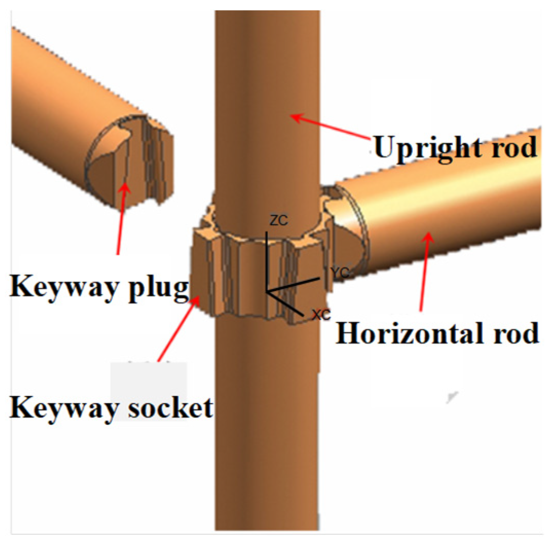
2.1. Experimental Design

A full-scale test was carried out on two types of socket-type keyway steel pipe scaffoldings with different cantilever heights, which were used to study the damage pattern and ultimate load capacity of this novel type of scaffolding. The overall arrangement of the two types of steel pipe scaffoldings is shown in Figure 2. The specifications of the component materials used in the tests are shown in Table 1. The upright rods are connected by a trocar. Horizontal rods and diagonal rods are connected using rod-end keyed plugs. The detail of the rod-end connection is shown in Figure 3. In the two test schemes, the spacing of the upright rod is 1 m, and the step distance of the upright rod is 1.5 m or 1 m. The elongation length of the top cantilever end of scheme I is 1.2 m, while the elongation length of the top cantilever end of scheme II is 0.65 m. The test schemes of the whole scaffolding are shown in Table 2.

2.2. Loading Program and Measurement Point Arrangement

The test was carried out by self-balancing loading. Uniform and symmetrical loading of the whole scaffolding was applied by two 100 t jacks at the bottom, reaction beams, and a double-layer distribution beam at the top. The loading device for the test is shown in Figure 4. The applied load is 10 kN per stage for scheme I and 20 kN for scheme II. Each level of loading lasted for 10 min. Eventually, the entire scaffolding was destroyed.
The arrangement of the strain measurement points is shown in Figure 5. Measurement points 1, 3, 5, and 7 are located on the south side of the cantilever end of the upright rod. Measurement points 2, 4, 6, and 8 are located on the east side of the cantilever end of the upright rod. Measurement points 9, 10, and 11 are located in the middle of the uppermost horizontal rod. Measurement points 12 and 13 are located in the middle of the uppermost diagonal rod.

3. Experimental Results and Analysis

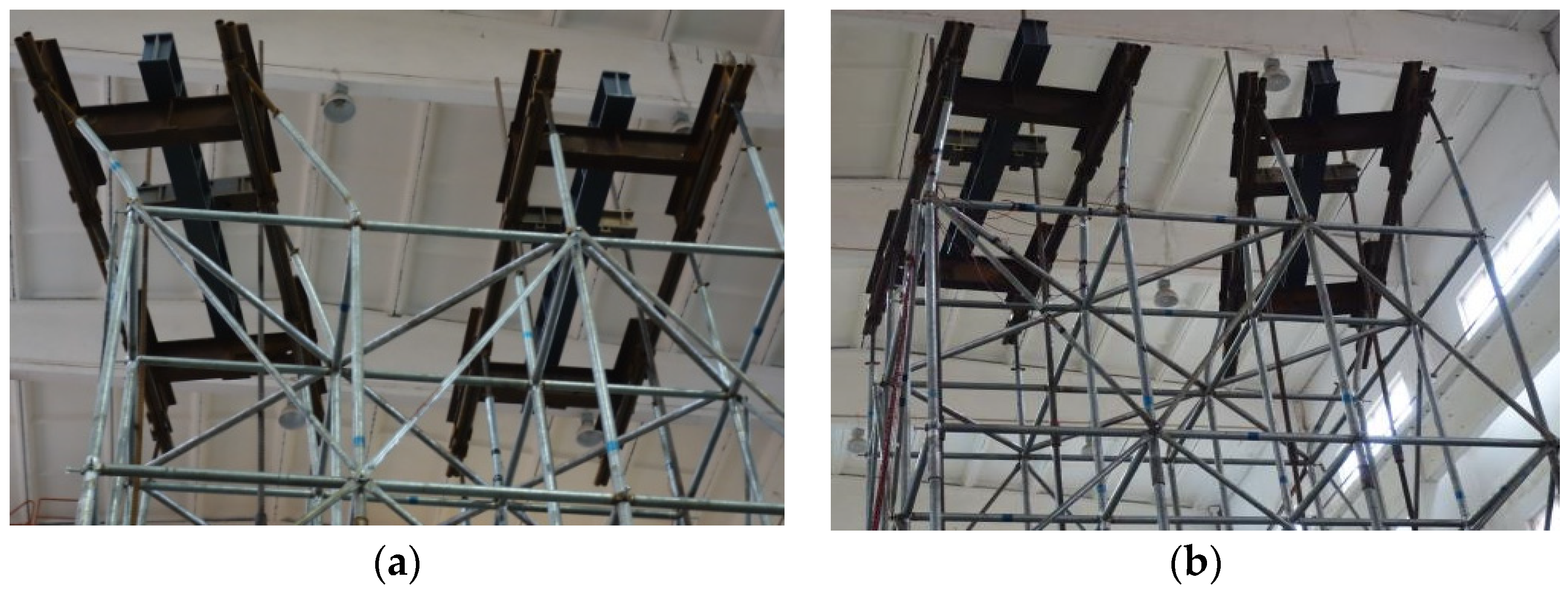
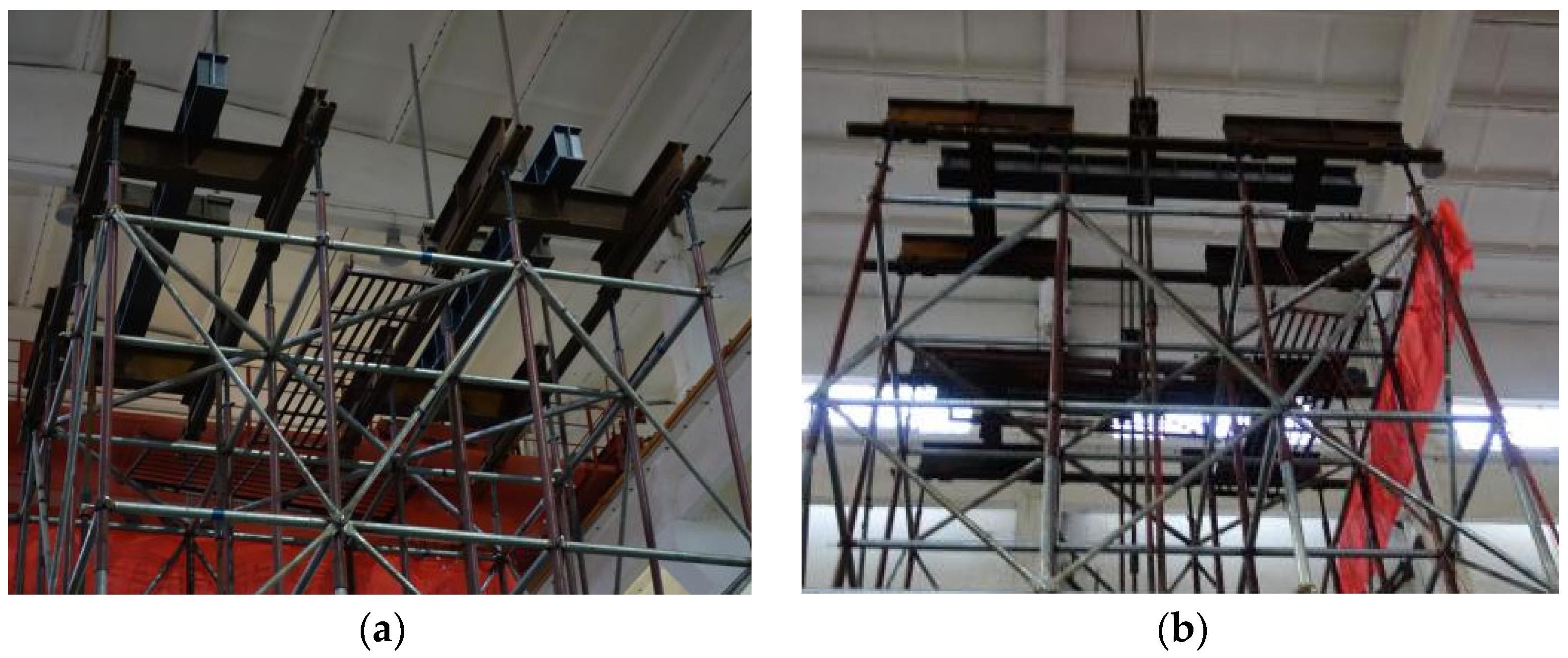
3.1. Experimental Phenomena

Scheme I: As shown in Figure 6a, due to the failure of the loading equipment, the two rows of upright rods on the north side of the scaffolding broke down when the load was 130 kN. The two rows of upright rods on the south side of cantilever end buckled when loaded to 160 kN (Figure 6b). At 180 kN, the bending deformation at the lower end node of the cantilever end rapidly developed, and the cantilever end tilted northward. The ultimate load capacity of the final frame damage was 196 kN, and the instability mode was localized instability (Figure 7a).
Scheme II: As shown in Figure 8a, there was no significant deformation of the frame when the load was 140 kN. The middle four upright rods exhibited slight deformation when loaded to 200 kN (Figure 8b). Eventually, the cantilever end bends to the south when loaded to 260 kN. The middle four upright rods bent to the north at the fourth to sixth (between the horizontal reinforcement layers) levels of the horizontal rods. The whole frame was destabilized by half-wave drumming (Figure 7b).

3.2. Load-Strain Curve

The load-strain curves at each measurement point of scheme I and scheme II in the test are shown in Figure 9 and Figure 10, respectively. The strains of the upright rods were close to 0.1ε in both schemes when the steel pipe scaffolding suffered destabilizing damage. The lower end of the cantilever end of the upright rod reached the yield stage when the scaffolding was damaged, while the strains in the horizontal rod and the vertical diagonal brace were low. This is because the scaffolding was mainly subjected to vertical loads, and the rods were mainly subjected to axial forces. Therefore, under the action of a vertical load, vertical rods were subjected to larger loads, while horizontal rods and vertical diagonal braces were subjected to smaller forces. Thus, the strains measured in the horizontal rods and vertical diagonal braces were small compared to the strains in the upright rods.
The two rows of upright rods on the north side of the scaffolding in scheme I broke down when the load was 130 kN (Figure 6a). Therefore, the test results do not take into account the two rows of upright rods on the north side. The final form of damage was a localized instability damage of the two rows of upright rods on the south side of the top tilted to the north side (Figure 6b and Figure 8a). The strains at measurement points 1, 3, 5, and 7 are much greater than the strains at measurement points 2, 4, 6, and 8 (Figure 9a,b).
The final form of damage in scheme II is overall destabilization damage. The cantilever ends of the upright rods deform in both directions (Figure 7a,b). Therefore, the strains at measurement points 1, 3, 5, and 7 of scheme II are closer to the values of the strains at measurement points 2, 4, 6, and 8 of scheme II (Figure 10a,b), and the strains in scheme II are smaller than the strains at measurement points 1, 3, 5, and 7 of scheme I (Figure 9a).

3.3. Analysis of Test Results

The length of the cantilever end of the scaffolding in scheme I is longer. The localized instability at the cantilever end resulted in the entire scaffolding not being able to continue loading. The length of the cantilever end of the scaffolding in scheme II is half the length of the cantilever end of the frame in scheme I. The ultimate load capacity of scheme II is 33% greater than that of scheme I. The final damage form of the scaffolding of scheme II was overall destabilization with good stability. The elongation length of the cantilever end determines the load capacity of the two scaffolding schemes as well as the difference in the modes of instability. Compared with that in Scheme I, the elongation of the cantilever end in Scheme II is greatly reduced. The final damage form of the scaffolding changes from local instability to overall instability, and the stability of the formwork improves.

4. Stability Analysis of Socket-Type Keyway Steel Pipe Scaffolding

4.1. Introduction of the Theory of Second-Order Bending Moment Effects

The instability failure of steel structures can be divided into two categories [23,24]: equilibrium bifurcation instability and limiting point instability. The instability problem of the steel scaffolding studied in this paper is limiting point instability. The upright rod is subjected mainly to pressure and bending moments (including initial and second-order moments). The initial bending moments of the structure are mainly due to the initial geometric defects of the structure or the bending moments due to lateral loads. Second-order bending moments are those produced by the  P - δ  and  P - Δ  effects. The  P - δ  effect refers to the axial force applied by a rod under the action of flexural deformation to produce an additional bending moment effect. The  P - Δ  effect is the effect of the additional bending moment produced by the horizontal deformation of the bar. In the stability calculation of steel scaffolding, the influence of second-order effects is added to the analyzed factors [25]. Lateral-free stiffeners are generally considered for the  P - δ  effect. The influence of the  P - Δ  effect also needs to be considered in a rigid frame with lateral displacement.

4.2. Introduction of the Semirigid Node Theory

Connection nodes are generally categorized into three forms: rigid, articulated, and semirigid connections [26,27,28]. The upright rods and horizontal rods of the steel scaffolding will rotate relatively during the force process. The connecting nodes of the scaffolding are neither rigid nor articulated. Rather, they are typically semirigid nodes [29,30].
Much research has been carried out on semirigid nodes by previous authors [31]. The rotational stiffness [32] of the semirigid nodes is the most significant factor affecting the overall stress performance of the structure. The rotational stiffness of a semirigid node is related to several factors. The rotational stiffness of a semirigid node can be calculated by the following method:
(1)
Experimental methods
The moment-displacement curves of the nodes are obtained by measuring the rotational stiffness of the nodes in the tests. The experimental method allows a more realistic determination of the rotational stiffness of the nodes. The experimental method requires statistical analysis through a large amount of experimental data.
(2)
Finite element method
The finite element method is a method applicable to a wide range of problems that can be solved within the field of engineering. Numerical simulation of the connection performance of the nodes is carried out using engineering software. The effect of different factors on the structure can be considered. This approach can be further applied to nonlinear problems [33,34].
The socket-type keyway steel pipe scaffolding is a type of semirigid connected steel frame with lateral movement, according to theoretical analysis [35,36,37]. The rotational stiffness of this type of semirigid node was derived as  K = 12.02   k N m / rad  [22] from a large number of tests carried out by previous authors using an experimental method. In contrast, Yu [38] used a computational model of three-story frame columns with coil springs to simulate the restraining moments of beams on columns and the semi-stiffness of nodes.

5. Finite Element Analysis

5.1. Selection of Finite Element Software
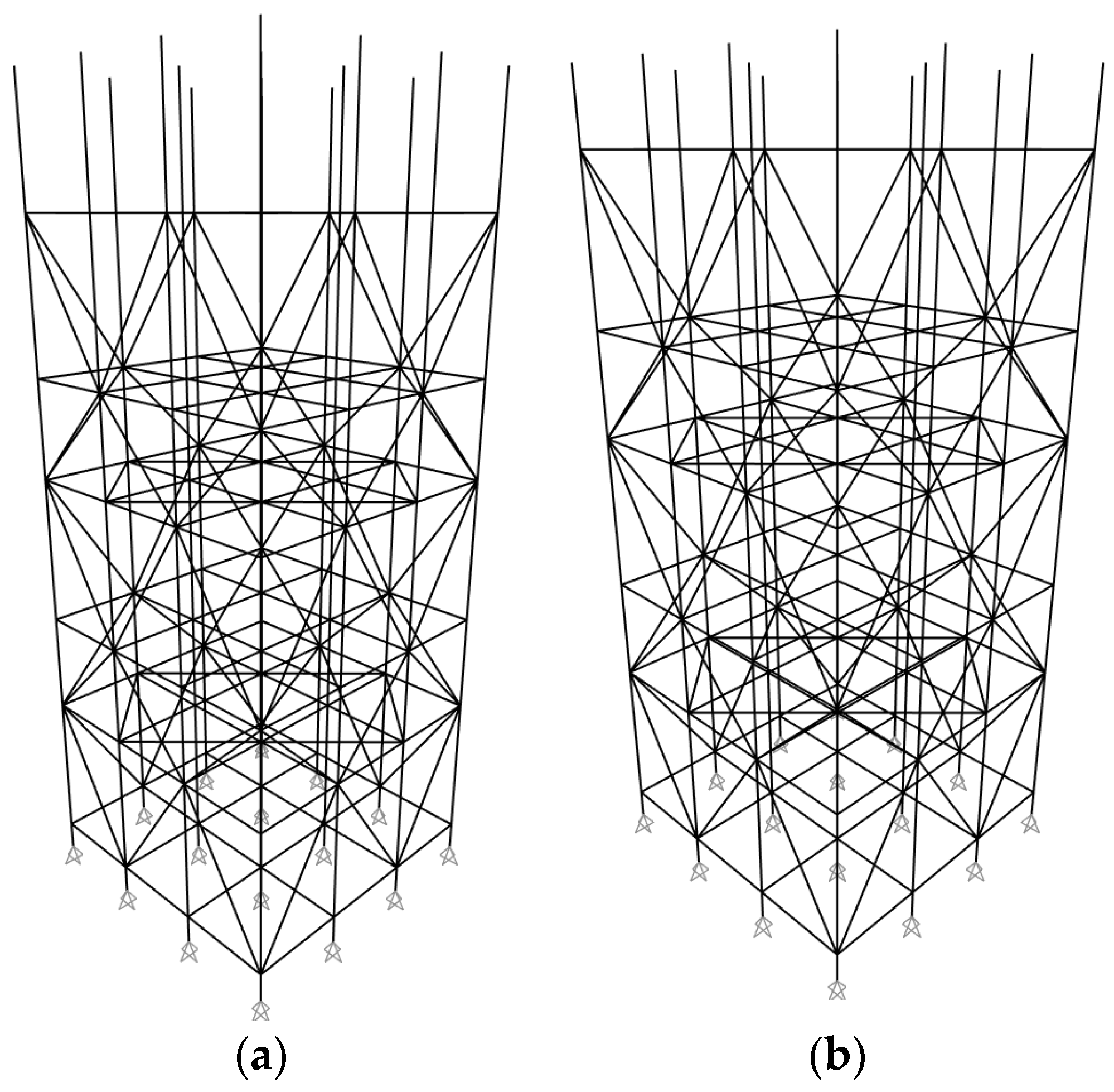
Finite Element Analysis (FEA) is a modern computational method that has been rapidly developed for the analysis of structural mechanics. In the field of building structures, the more commonly used general-purpose finite element software are mainly Ansys, PKPM, Midas, Abaqus and SAP2000. SAP2000 v21 is used in this article for finite element modeling and computation.
SAP2000 is a powerful structural analysis software that integrates static-dynamic analysis, load calculation, linear and nonlinear calculation, and other computational analysis in a single package. It contains the latest techniques for static, dynamic, linear and nonlinear analysis, and the calculation process is easy and the results are accurate. The linear elastic buckling analysis and geometric nonlinear analysis contained in the SAP2000 program matches very well with the computational analysis required by the analytical model of the socket-type keyway steel pipe scaffolding. Therefore, SAP2000 is adopted as the analysis software in this article.
In the finite element modeling of the socket-type keyway steel pipe scaffolding, we need to use mainly point objects and line objects. Point objects appear in the form of nodes, which are the most basic units in a structural system. Constraints, springs, loads, connection properties, etc., can be defined and modified in SAP2000 for specified point objects. In the line object, it is possible to define section types, end constraints and displacements, stiffness corrections, connection properties, concentrated and line loads, and even temperature effects on the line object.

5.2. Modeling

SAP2000 software was used to analyze the modeling formwork for two different erection schemes. The upright rods, horizontal rods, and horizontal diagonal rods of the scaffolding are made of round steel pipes with dimensions of Φ48 × 3.0. The vertical diagonal rods are made of Φ32 × 2.0 round steel pipes. The steels are Q235 carbon structural steel. The modulus of elasticity of the steel is taken as E = 206 MPa, Poisson’s ratio is V = 0.3, and the mass density is 7850 kg/m3. The upright rods are assumed to be rigidly connected. The connection nodes of the upright rods and horizontal rods are considered semirigid nodes. The rotational stiffness of the node is  K = 12.02   k N m / rad . Both horizontal and vertical inclined rods are defined as rods articulated at both ends and only axial forces are considered. The support constraint is assumed to be an articulated support that constrains displacements in the X, Y, and Z directions.
The finite element models of scheme I and scheme II are shown in Figure 11.

5.3. Linear Elastic Buckling Analysis

Eigenvalue buckling analysis [39] is also known as linear elastic buckling analysis. Mathematically, this process results in a generalized eigenvalue problem, which involves the analysis of first-order linear elastic instability without considering second-order  P - δ  (additional effects caused by the deflection of the member under axial pressure) or  P - Δ  (additional effects of gravity caused by the horizontal deformation of the member). The eigenvalue equations are solved to determine the ultimate load and damage pattern of the structure when buckling occurs.
Unit loads were applied to the top cantilever end of each upright rod during linear elastic buckling analysis. Buckling was selected for the load type. After the number of flexural modes and the eigenvalue convergence tolerance are defined, the flexural factor is analyzed. The buckling load is determined from the product of the buckling factor and the given unit load. The results of the instability modes for the linear elastic buckling analysis of scheme I and scheme II are shown in Figure 12.
The structural instability modes obtained from the finite element linear elastic buckling analysis are consistent with those of the scaffolding tests. The ultimate load capacities of the single upright rods of the whole scaffolding of scheme I and scheme II calculated in SAP2000 were 21.22 kN and 43.14 kN, respectively. The ultimate load capacities obtained from the tests of scheme I and scheme II were 24.50 kN and 34.50 kN, respectively. As shown in Table 3, the calculated results for scheme I are 15% lower than the experimental results. The calculated results for scheme II are 25% greater than the experimental results.
The finite element analysis results reveal that the damage to the scaffolding in scheme I is a localized instability. The cantilevered end of the top of the upright rod was displaced significantly, and the upper portion of the upright rod was displaced very little. The cantilevered end of the top of the upright rod has a greater elongation length. The ultimate load capacity of the scaffolding is mainly determined by the cantilever end. The damage to the scaffolding in scheme II is an overall instability. The cantilever end of the top of the upright rod was displaced, and the upper portion of the upright rod was also significantly displaced. The ultimate load-carrying capacity does not depend solely on the length of the cantilevered end at the top of the upright rod. The higher ultimate load capacity calculated from the finite element analysis of scheme II than that obtained from the test results occurs because second-order effects and the influence of initial geometric imperfections were not considered in the linear elastic buckling analysis. Therefore, it is necessary to perform a buckling analysis of the scaffolding considering the second-order effects and the initial geometrical defects.

5.4. Geometric Nonlinear Buckling Analysis

The influence of second-order effects should be taken into account when analyzing with finite element software, which is more in line with the force and deformation of the structure under actual working conditions. The over-extension of the cantilever end at the top of the upright rod in scheme I resulted in the ultimate load capacity of the scaffolding being determined by the cantilever end at the top of the upright rod. Localized instability at the cantilever end resulted in the scaffolding not being able to continue to carry the load. The damage to the scaffolding in scheme II is an overall instability. The geometric nonlinear buckling analysis [40] of scheme II considering initial defects was performed by the finite element software SAP2000. The modeling requires attention to the following two points:
(1)
The load conditions are defined differently. The buckling analysis case is not chosen for modeling; instead, the static nonlinear loading case is defined. The  P - Δ  effect is selected among the geometric nonlinear parameters. The material nonlinear parameters and nonlinear solution control options are set so that the calculation results can converge.
(2)
There are three general approaches to nonlinear analysis considering initial geometric defects. The first is the direct simulation of defects, which means that definite initial defects are introduced directly into the finite element model, taking into account the influence of factors such as installation errors and machining processes of the components. The second approach takes into account the effects on the structure due to initial geometric defects by reducing the tangent modulus of the material. The third method is to apply a smaller lateral load in the buckling direction of the structure based on the buckling modal map obtained in the eigenvalue buckling analysis. The most unfavorable effect is obtained by lateral loading. The magnitude of lateral loads is generally taken as 0.5–0.1% of the vertical force. The third method of analysis is used in this paper; 0.5% of the vertical force is taken as the lateral load value.
As shown in Figure 13, the point at which the maximum displacement occurs is the top point of the cantilever end according to the geometric nonlinear buckling analysis of scheme II. The ultimate capacity of a single upright rod of the structure in the second-order nonlinear buckling analysis is 33.37 kN, which is less than the ultimate capacity in the linear elastic buckling analysis (43.14 kN) but closer to the test result (34.50 kN). The ultimate load capacity of a single upright rod in the second-order nonlinear buckling analysis has only a 4% error from the test results. The nonlinear buckling analysis considering the initial geometric defects is closer to the real force conditions of the structure.

6. Conclusions

(1)
For the socket-type keyway steel pipe scaffolding mentioned in this paper, local instability damage occurred at the top of the upright rod when the length of the upright rod at the cantilever end was long (1.2 m). When the length of the cantilever end upright rod is short (0.65 m), the scaffolding is damaged by overall destabilization.
(2)
The elongation length of the cantilever end at the top of the scaffolding has a significant effect on the load-bearing capacity. The length of the cantilever end of the scaffolding upright rod is reduced by about 50%, which can increase the ultimate load- carrying capacity of the upright rod by 40%.
(3)
The error between the ultimate load capacity in the linear elastic buckling analysis and the experimental results is 25%. In contrast, the error between the calculated ultimate bearing capacity in the nonlinear buckling analysis and the test results was 4%, which is much closer to the test results. Therefore, a buckling analysis of socket-type keyway steel pipes scaffolding was performed. It is recommended to use nonlinear buckling analysis that takes into account second-order effects and initial geometric defects. This is more in line with the forces on the structure in real situations.

Author Contributions

Conceptualization, C.Z., J.Y., L.J. and Y.H.; Methodology, C.Z.; Validation, C.Z.; Investigation, C.Z.; Resources, J.Y. and L.J.; Data curation, C.Z. and Y.H.; Writing—original draft, C.Z. and Y.H.; Writing—review & editing, C.Z. and Y.H.; Visualization, C.Z. and Y.H.; Supervision, J.Y. and L.J.; Project administration, C.Z. All authors have read and agreed to the published version of the manuscript.

Funding

This research was financially supported by the Hunan Province Engineering Construction Local Standard Making (Revision) Plan Project (Grant numbers: BZ20220005). The sponsor is Hunan Shaping construction Co., Ltd.

Data Availability Statement

Data are contained within the article.

Acknowledgments

The authors wish to acknowledge the National Engineering Laboratory’s technical support for High-Speed Railway Construction of the School of Civil Engineering, Central South University. Finally, and most importantly, the authors wish to thank the anonymous reviewers for their thorough evaluations and valuable comments, which have helped improve the paper.

Conflicts of Interest

Author Yanqing He was employed by the company Baoji Works Section of China Railway Xi’an Bureau Group Co., Ltd. The remaining authors declare that the research was conducted in the absence of any commercial or financial relationships that could be construed as a potential conflict of interest.

References

  1. Mi, J. Technology Progress of Formwork and Scaffold Industry in China. Constr. Technol. 2011, 40, 60–63+76. [Google Scholar]
  2. Zhu, Z. Stable Analysis on Fastener Type Full Formwork Support. Master’s Thesis, Anhui Jianzhu University, Hefei, China, 2021. [Google Scholar]
  3. Zheng, W. Experimental Study on Integral Stability of Steel Tubular Scaffold with Arch Skeleton Frames. Fujian Constr. Sci. Technol. 2021, 5, 19–20+51. [Google Scholar]
  4. Sun, Q. Experimental Investigation on the Mechanical Behaviour and Stability of Full Cuplock Steel Tubular Scaffolding. Master’s Thesis, Changan University, Xi’an, China, 2018. [Google Scholar]
  5. Huang, H. Application and Safety Supervision of Socket-and-Buckle Scaffold in Construction Engineering. Jiangsu Build. Mater. 2022, 107–109. [Google Scholar]
  6. Xie, Q.; Jin, G.; Wang, Y. Situation of Scaffold in Our Country and Its Development Trends. Constr. Mech. 2006, 27, 17–21. [Google Scholar]
  7. Wang, S.; Xiao, W.; Cheng, Z. Safety Accident and Prevention of Scaffolding in Construction Site. Value Eng. 2023, 42, 13–15. [Google Scholar]
  8. Tomasz, N.; Bożena, H. Methodology Based on Causes of Accidents for Forcasting the Effects of Falls from Scaffoldings Using the Construction Industry in Poland as an Example. Saf. Sci. 2023, 157, 105945. [Google Scholar]
  9. Halperin, K.M.; Michael, M. An Evaluation of Scaffold Safety at Construction Sites. J. Saf. Res. 2004, 35, 141–150. [Google Scholar] [CrossRef]
  10. Hwang, M.J.; Won, H.J.; Jeong, J.H.; Shin, S.H. Identifying Critical Factors and Trends Leading to Fatal Accidents in Small-Scale Construction Sites in Korea. Buildings 2023, 13, 2472. [Google Scholar] [CrossRef]
  11. Jia, L.; Liu, H.; Chen, Z. Experimental Research and FEA on Bearing Capacity of Full Hallsteel Tube and Coupler Scaffold Support System. J. Build. Struct. 2017, 38, 114–122. [Google Scholar]
  12. Ji, M.; Zeng, F.; Dong, Y.; Fan, Y. Calculation Method of Stable Bearing Capacity of Fastener-Type Steel Pipe Formwork Support Upright Rod. Appl. Sci. 2023, 13, 4838. [Google Scholar] [CrossRef]
  13. Liu, H.; Jia, L.; Wen, S.; Liu, Q.; Wang, G.; Chen, Z. Experimental and Theoretical Studies on the Stability of Steel Tube–Coupler Scaffolds with Different Connection Joints. Eng. Struct. 2016, 106, 80–95. [Google Scholar] [CrossRef]
  14. Dong, J.; Liu, H.; Lei, M. Overall Structural Stability Analysis on Wheel Coupler Formwork Support. China Saf. Sci. J. 2022, 32, 85. [Google Scholar]
  15. Yu, H.; Guo, S.; Liu, W.; Gao, R. Experimental Study on Stable Bearing Capacity of Wheel-Buckle Formwork Support Frames. Structures 2023, 48, 1175–1189. [Google Scholar] [CrossRef]
  16. Chen, Z.; Lv, J.; Liu, H.; Liu, Q.; Ye, B. Experimental and Analytical Studies on Stability of Ultra-Strong Thin-Walled Steel Tube and Coupler Scaffolds. Eng. Struct. 2023, 275, 115255. [Google Scholar] [CrossRef]
  17. Bian, Y. Experimental Research on Bearing Capacity of New Wheel Buckle Type of Steel Formwork Support. Master’s Thesis, Liaoning Technical University, Fuxin, China, 2017. [Google Scholar]
  18. Pieńko, M.; Błazik-Borowa, E. Experimental Studies of Ringlock Scaffolding Joint. J. Constr. Steel Res. 2020, 173, 106265. [Google Scholar] [CrossRef]
  19. Zhang, L.; Liu, J.; Tang, Q.; Liu, Z. A Numerical Study on Rotational Stiffness Characteristics of the Disk Lock Joint. J. Constr. Steel Res. 2023, 207, 107968. [Google Scholar] [CrossRef]
  20. Zhang, L.; Lin, B.; Qi, H. Study on the Finite Element Calculation Method of the Bearing Cross Bar of Keyway-Quick Locked Scaffold. In Proceedings of the 8th National Steel Structure Engineering Technology Exchange Meeting, Construction Technology, Xi’an, China, 29 October 2020. [Google Scholar]
  21. Zhang, Z.; Chen, X.; Lin, B.; Cong, J.; Zhang, L. Study on Stability of Casting-Extended Scaffolding Steel Pipe under Axial Compression. J. Build. Struct. 2022, 43, 228–238. [Google Scholar]
  22. Xie, J. Experimental Research on Mechanical Behavior of Sockettype Steel Tubular Scaffold. Master’s Thesis, Central South University, Changsha, China, 2014. [Google Scholar]
  23. Xie, Q. Study on Seismic Design Method Based on P–Δ Effects of Steel Frame. Ph.D. Thesis, Xi’an University of Architecture and Technology, Xi’an, China, 2012. [Google Scholar]
  24. Wang, S.; Zhang, Z.; Wang, C.; Zhu, C.; Ren, Y. Multistep Rocky Slope Stability Analysis Based on Unmanned Aerial Vehicle Photogrammetry. Environ. Earth Sci. 2019, 78, 260. [Google Scholar] [CrossRef]
  25. Yin, T.; Wang, Z.; Pan, J.; Zheng, K.; Liu, D.; Lu, S. A Design Method for Semi-Rigid Steel Frame via Pre-Established Performance-Based Connection Database. Buildings 2022, 12, 1634. [Google Scholar] [CrossRef]
  26. Xu, M. The Research on Mechanical Behavior of Steel Frames with Semi-Rigid Connections. Master’s Thesis, Changsha University of Science & Technology, Changsha, China, 2005. [Google Scholar]
  27. Li, Y.; He, R. Research for the Semi-Rigid Connection in Frame Structure. J. Harbin Univ. Civ. Eng. 1994, 27, 112–119. [Google Scholar]
  28. Goverdhan, A. A Collection of Experimental Moment-Rotation Curves and Evaluation of Prediction Equations for Semi-Rigid Connections. Ph.D. Thesis, Vanderbilt University, Nashville, TN, USA, 1983. [Google Scholar]
  29. Chen, W.F.; Kishi, N. Semi-Rigid Steel Beam-to-Column Connection: Data Base and Modeling. J. Struct. Eng. Struct. ASCE 1989, 25, 105–119. [Google Scholar] [CrossRef]
  30. Xu, L.; Liu, Y. Story Stability of Semi-Braced Steel Frame. J. Constr. Steel Res. 2002, 58, 467–491. [Google Scholar] [CrossRef]
  31. Yao, H.; Huang, Y.; Ma, W.; Liang, L.; Zhao, Y. Dynamic Analysis of a Large Deployable Space Truss Structure Considering Semi-Rigid Joints. Aerospace 2023, 10, 821. [Google Scholar] [CrossRef]
  32. Nawar, M.T.; Matar, E.B.; Maaly, H.M.; Alaaser, A.G.; El-Zohairy, A. Assessment of Rotational Stiffness for Metallic Hinged Base Plates under Axial Loads and Moments. Buildings 2021, 11, 368. [Google Scholar] [CrossRef]
  33. Rui, C. Study and Design of the Static Behavior of Steel Truss Joints of Transmission Towers. Ph.D. Thesis, Chongqing University, Chongqing, China, 2010. [Google Scholar]
  34. Cao, G. Experimental and Theory Study On Unstiffened and Typical Stiffened Steel Tubular Joints of Large-Span-Weight Structures. Ph.D. Thesis, Tongji University, Shanghai, China, 2006. [Google Scholar]
  35. Chen, Z.; Lu, Z.; Wang, X.; Liu, H.; Liu, Q. Experimental and Theoretical Research on Capacity of Unbraced Steel Tubular Formwork Support Based on Sway Frame with Semi-Rigid Connection Theory. J. Build. Struct. 2010, 31, 11–15. [Google Scholar]
  36. Li, G.; Wang, J.; Liu, Q. A Practical Approach for the Design of Semi-Rigid Composite Frames under Vertical Loads (I)—Design of Beam-to-Column Connections. Prog. Steel Build. Struct. 2006, 6, 27–37. [Google Scholar]
  37. Zhang, G.; Lv, X.; Liu, J. Displacement-Based Seismic Design of High-Strength Concrete Frame Columns with Confinements. J. Tongji Univ. Sci. 2007, 35, 143–148. [Google Scholar]
  38. Yu, W.; Wang, Z. Effective Length of Columns in Sway and Sem-rigid Steel Frames. Build. Sci. 2008, 24, 17–19. [Google Scholar]
  39. Shahin, R.I.; Ahmed, M.; Yehia, S.A. Elastic Buckling of Prismatic Web Plate under Shear with Simply-Supported Boundary Conditions. Buildings 2023, 13, 2879. [Google Scholar] [CrossRef]
  40. Yao, X.; Yang, J.; Guo, Y. Study on Restoring Force Model of Cold-Formed Thin-Walled Steel Lipped Channel Beam-Columns under Cyclic Load. Buildings 2023, 13, 114. [Google Scholar] [CrossRef]
Figure 1. The structural layout of the all-steel attached lifting protection platform.
Buildings 14 00245 g001
Figure 2. The overall layout of the test model. (a) Scheme I. (b) Scheme II.
Buildings 14 00245 g002
Figure 3. Detail of rod-end connection. (a) Connection of upright rods with horizontal rods and diagonal rods. (b) Connection of upright rods.
Buildings 14 00245 g003
Figure 4. Loading setup diagram. (a) Side view. (b) Top view. (c) Detail of loading device.
Buildings 14 00245 g004
Figure 5. Arrangement of the strain measuring points in schemes I and II.
Buildings 14 00245 g005
Figure 6. Instability morphology of scheme I. (a) West elevation. (b) East elevation.
Buildings 14 00245 g006
Figure 7. Instability mode of schemes I and II. (a) Instability mode of scheme I;. (b) Instability mode of scheme II.
Buildings 14 00245 g007
Figure 8. Instability morphology of scheme II. (a) West elevation. (b) South elevation.
Buildings 14 00245 g008
Figure 9. Load—strain curves at the measurement point points in scheme I. (a) Upright rod load-strain diagram 1. (b) Upright rod load-strain diagram 2. (c) Horizontal rod load-strain diagram. (d) Diagonal rod load-strain diagram.
Buildings 14 00245 g009
Figure 10. Load—strain curves at the measurement points in scheme II. (a) Upright rod load-strain diagram 1. (b) Upright rod load-strain diagram 2. (c) Horizontal rod load-strain diagram. (d) Diagonal rod load-strain diagram.
Buildings 14 00245 g010
Figure 11. Finite element model. (a) Scheme I. (b) Scheme II.
Buildings 14 00245 g011
Figure 12. Finite element analysis model. (a) Destabilization mode of scheme I. (b) Destabilization mode of scheme II.
Buildings 14 00245 g012
Figure 13. Second-order buckling model for scheme II.
Buildings 14 00245 g013
Table 1. Specification of component materials.
ComponentSection FormNorm (mm)Thicknesses (mm)Material
Upright rodHot-dip galvanized welded steel pipeØ 483.0Q235
Horizontal rodWelded steel pipeØ 483.0Q235
Diagonal rodRound steel tubeØ 322.0Q235
Table 2. Model parameters of the scaffolding test.
Experiment SchemeSpecificationsHorizontal Diagonal
Brace
Vertical BraceLength of
Cantilever End
IThree hurdles and six stepsThree-layer setupSurrounding facades1.2 m
IIThree hurdles and six stepsThree-layer setupSurrounding facades0.65 m
Table 3. Ultimate load capacity from test and finite element analysis.
SchemeTestFEAErrors
I24.50 kN21.22 kN15%
II34.50 kN43.14 kN25%
Disclaimer/Publisher’s Note: The statements, opinions and data contained in all publications are solely those of the individual author(s) and contributor(s) and not of MDPI and/or the editor(s). MDPI and/or the editor(s) disclaim responsibility for any injury to people or property resulting from any ideas, methods, instructions or products referred to in the content.

