
Shear Bearing Capacity of Steel-Fiber-Reinforced Concrete Shear Wall under Low-Cycle Repeated Loading Based on the Softened Strut-and-Tie Model


Abstract
:1. Introduction
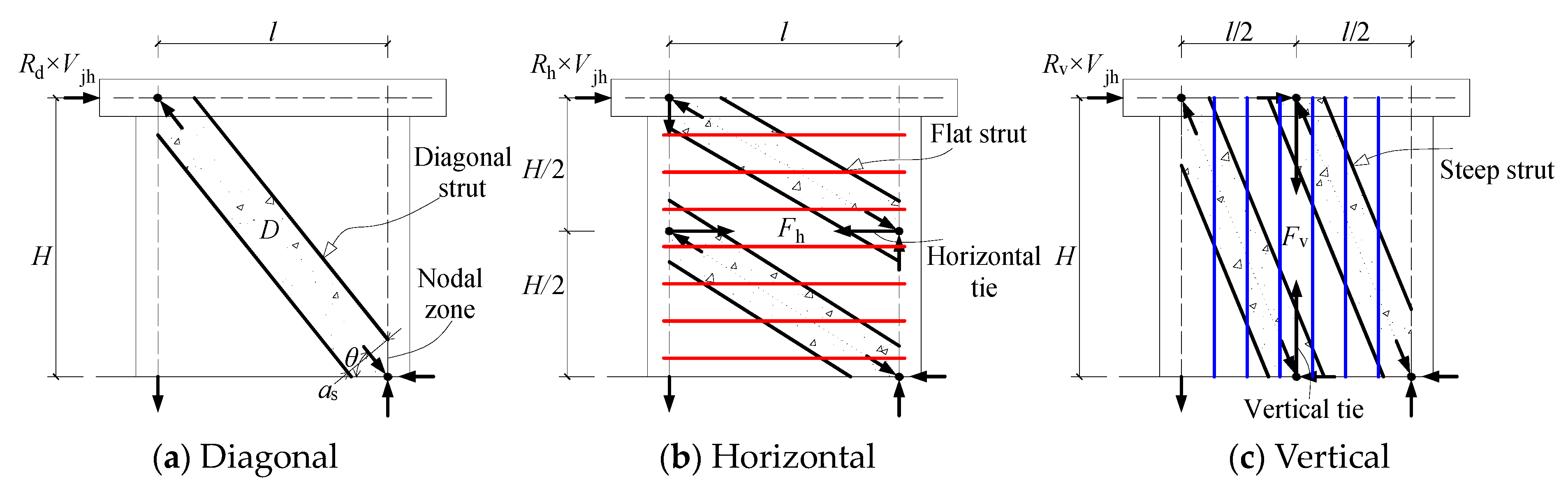
2. Loading Mechanism of SFRC SW
3. Computation Method for SBC of SFRC SW
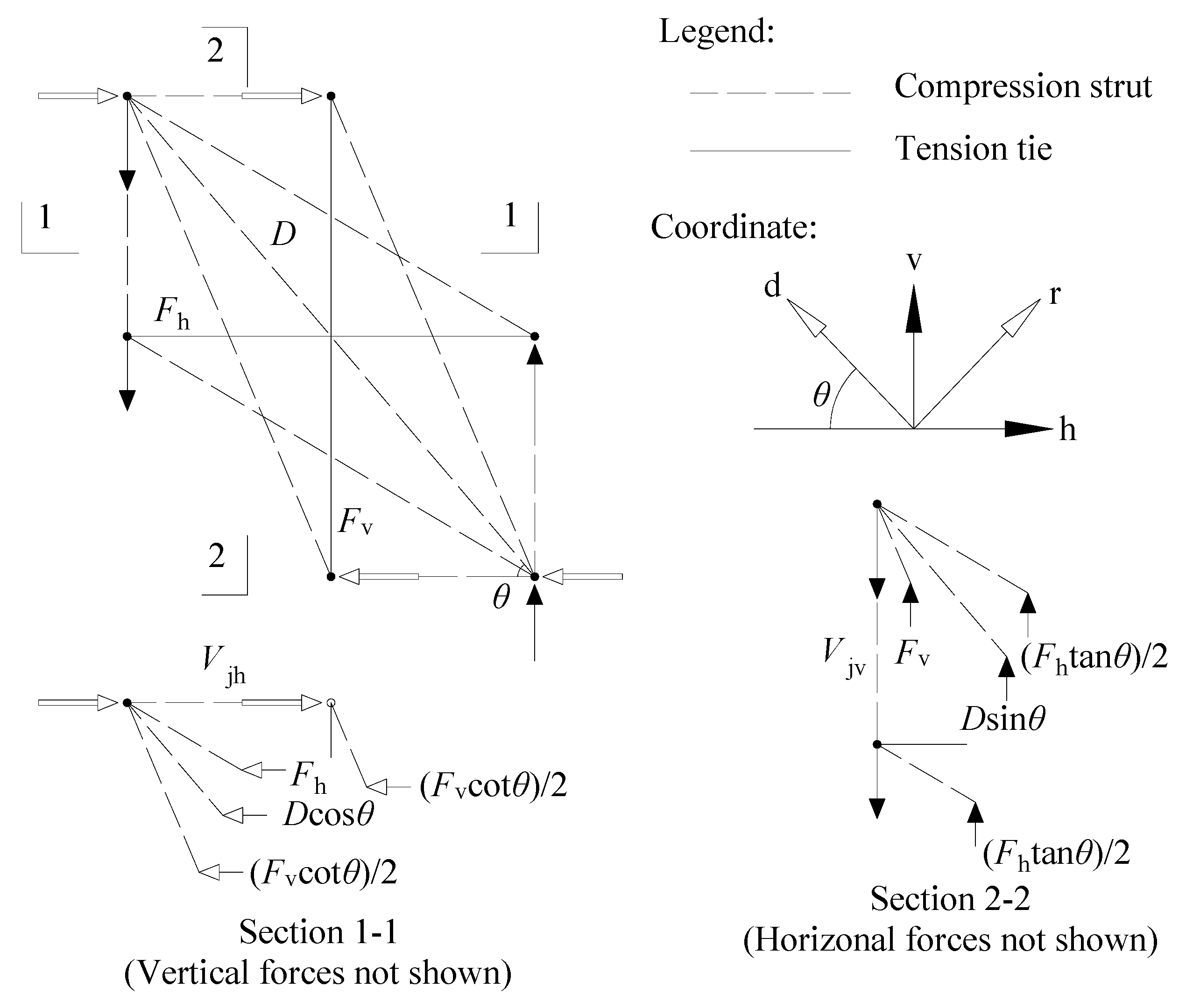
3.1. Equilibrium Equations
3.2. Constitutive Equations
3.3. Compatibility Equations
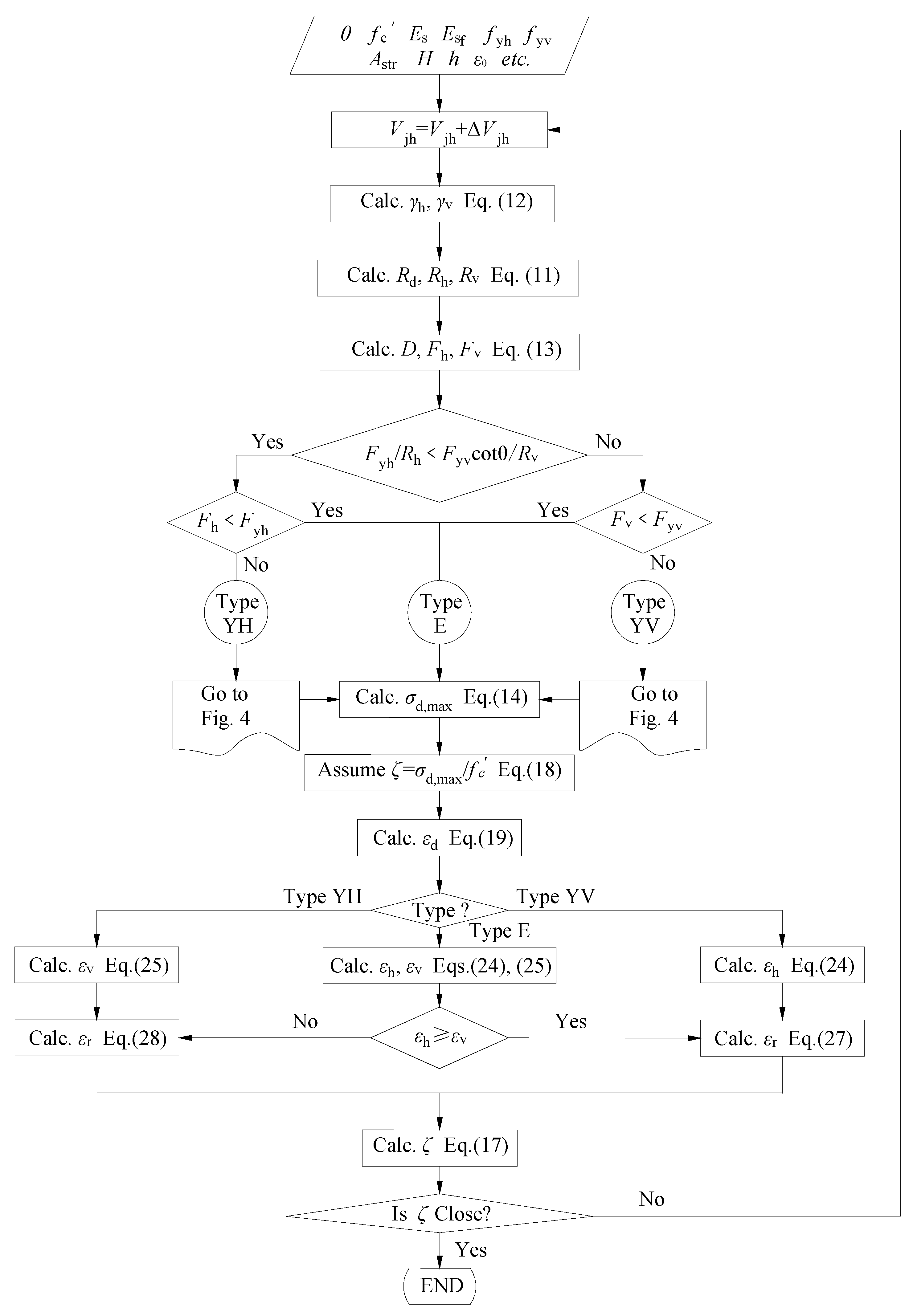
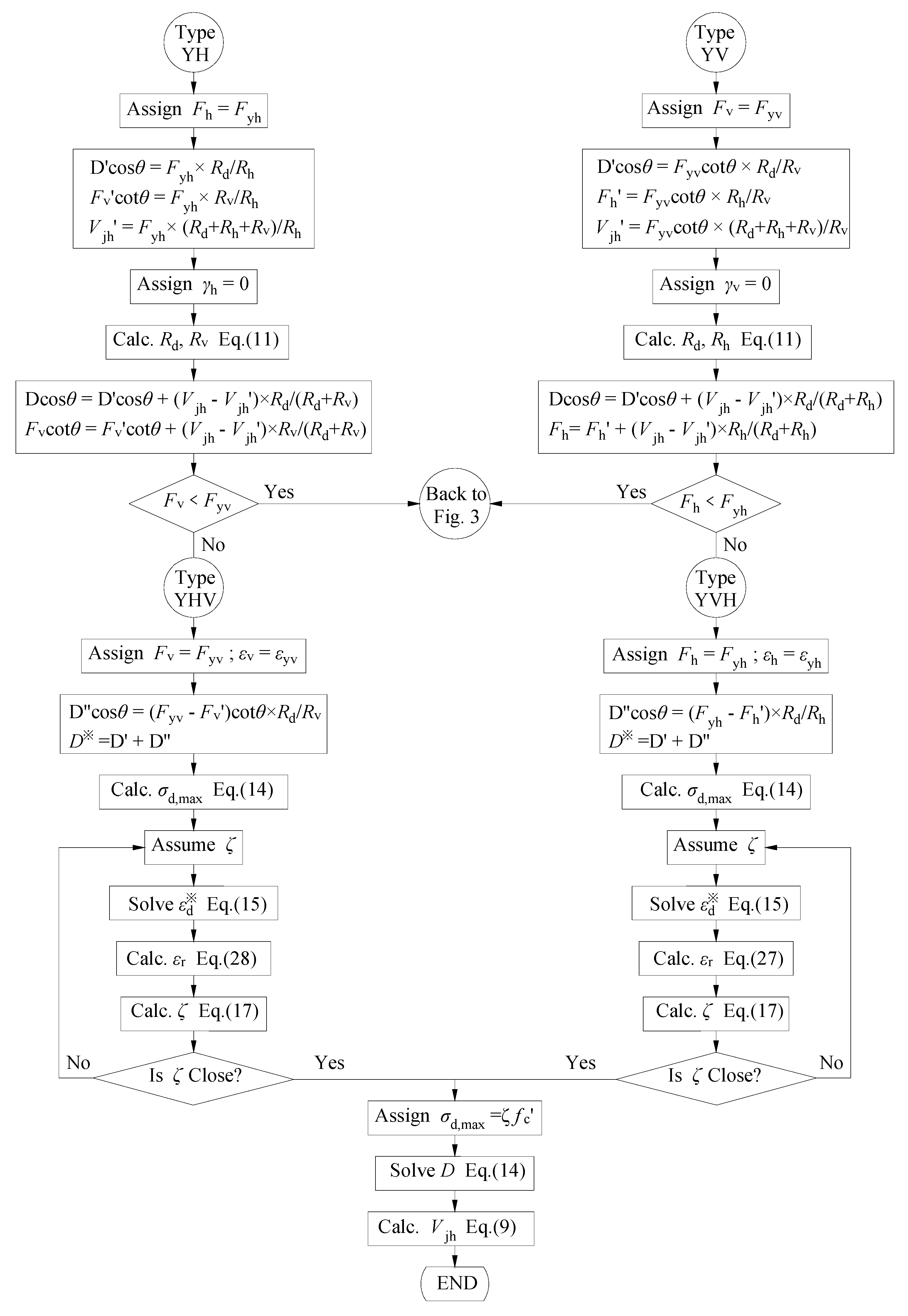
3.4. Solution Steps
4. Test Verification

| Specimen | Strength Grade | Material Consumption/(kg·m−3) | ρf | |||||
|---|---|---|---|---|---|---|---|---|
| Cement | Water | Steel Fiber | Sand | Crushed Stone | Water-Reducing Agent | |||
| RC-1.0-00-C60 | C60 | 529 | 164 | 0 | 646 | 1110 | 5.819 | 0 |
| RC-1.0-10(H)-CF60 | CF60 | 529 | 164 | 78 | 646 | 1110 | 5.819 | 1.0% |
| SW-05-40 [45] | CF40 | 454 | 168 | 39 | 676 | 1152 | —— | 0.5% |
| SW-10-40 [45] | CF40 | 476 | 176 | 78 | 719 | 1079 | —— | 1.0% |
| SW-15-40 [45] | CF40 | 503 | 186 | 117 | 740 | 1021 | —— | 1.5% |
| SW-20-40 [45] | CF40 | 524 | 194 | 156 | 779 | 953 | —— | 2.0% |
| SW-10-30 [45] | CF30 | 436 | 196 | 78 | 763 | 1054 | —— | 1.0% |
| FSW1 [46] | CF60-CF70 | 550 | 165 | 78 | 374 | 1326 | 5.5 | 1.0% |
| FSW2 [46] | CF60-CF70 | 550 | 165 | 117 | 369 | 1309 | 5.5 | 1.5% |
| FSW3 [46] | CF60-CF70 | 550 | 165 | 156 | 366 | 1299 | 5.5 | 2.0% |
| FSW4 [46] | CF60-CF70 | 550 | 165 | 78 | 374 | 1326 | 5.5 | 1.0% |
| Specimen | fc/MPa | H/mm | b × h/mm | n | Horizontal Reinforcement | Vertical Reinforcement | Steel Fiber | Vjh,t/kN | Vjh,c/kN | Vjh,t /Vjh,c | |||
|---|---|---|---|---|---|---|---|---|---|---|---|---|---|
| Reinforcement | fyh/MPa | Reinforcement | fyv/MPa | lf/df | ρf/% | ||||||||
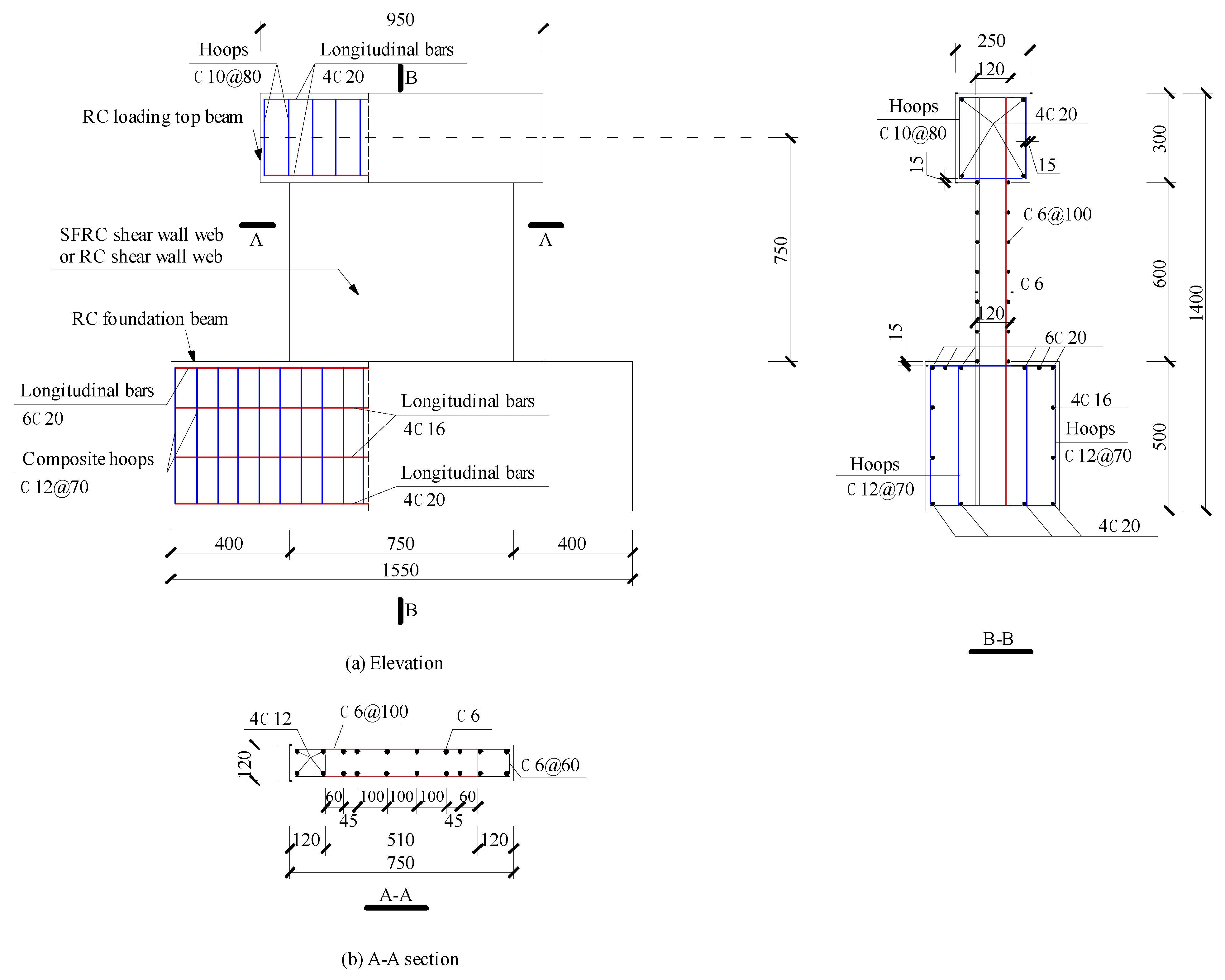
| RC-1.0-00-C60 | 55.4 | 750 | 120 × 750 | 0.2 | ϕ6@100 | 369.17 | 12ϕ6 | 369.17 | — | — | 546 | 552 | 0.989 |
| RC-1.0-10(H)-CF60 | 55.6 | 750 | 120 × 750 | 0.2 | ϕ6@100 | 369.17 | 12ϕ6 | 369.17 | 64 | 1.0 | 630 | 629 | 1.002 |
| SW-05-40 [45] | 21.2 | 900 | 200 × 900 | 0.1 | ϕ8@150 | 340 | 6ϕ14 | 373.5 | 57 | 0.5 | 730 | 608 | 1.201 |
| SW-10-40 [45] | 26.8 | 900 | 200 × 900 | 0.1 | ϕ8@150 | 340 | 6ϕ14 | 373.5 | 57 | 1.0 | 745 | 730 | 1.021 |
| SW-15-40 [45] | 25.1 | 900 | 200 × 900 | 0.1 | ϕ8@150 | 340 | 6ϕ14 | 373.5 | 57 | 1.5 | 770 | 748 | 1.029 |
| SW-20-40 [45] | 26.9 | 900 | 200 × 900 | 0.1 | ϕ8@150 | 340 | 6ϕ14 | 373.5 | 57 | 2.0 | 808 | 792 | 1.020 |
| SW-10-30 [45] | 17.8 | 900 | 200 × 900 | 0.1 | ϕ8@150 | 340 | 6ϕ14 | 373.5 | 57 | 1.0 | 730 | 586 | 1.246 |
| FSW1 [46] | 36.0 | 600 | 70 × 1000 | 0.09 | 6ϕ6.5 | 310 | 6ϕ6.5 | 310 | 64 | 1.0 | 335 | 431 | 0.777 |
| FSW2 [46] | 33.5 | 600 | 70 × 1000 | 0.09 | 6ϕ6.5 | 310 | 6ϕ6.5 | 310 | 64 | 1.5 | 330 | 436 | 0.757 |
| FSW3 [46] | 35.0 | 600 | 70 × 1000 | 0.09 | 6ϕ6.5 | 310 | 6ϕ6.5 | 310 | 64 | 2.0 | 340 | 465 | 0.731 |
| FSW4 [46] | 34.5 | 600 | 70 × 1000 | 0.09 | 6ϕ6.5 | 310 | 8ϕ6.5 | 310 | 64 | 1.0 | 330 | 430 | 0.767 |
5. Conclusions
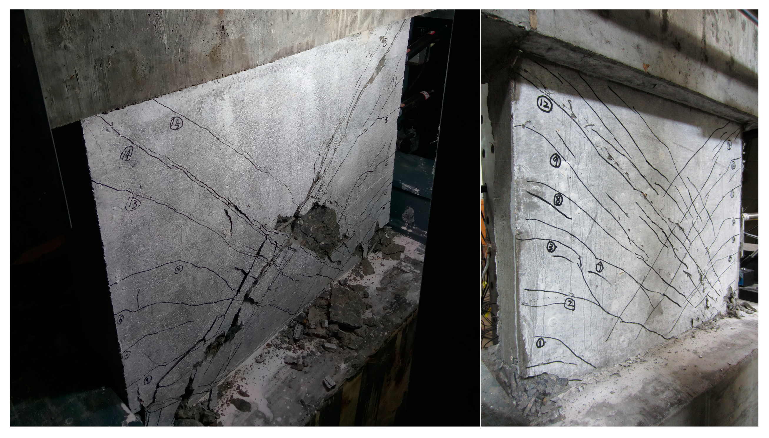
- The two SFRC SW specimens in this paper exhibited obvious shear failure characteristics, and all SFRC SW specimens primarily showed a typical diagonal cracking pattern after the test. The inclusion of SF notably improved the crack formation and seismic behavior of the HRB400 level high-strength reinforced concrete SW specimen. With an increase in the volume ratio of SF, the cracks of the SW specimen became thinner and denser. The crack distribution area significantly increased, and the amount of concrete crushing and spalling of the wall web was significantly reduced in the final failure of the SW specimen.
- The loading mechanism of SFRC SWs can be described by the SSTM. The SSTM of SFRC SWs, which consists of diagonal struts, horizontal, and vertical resistance members, has been established. This model distinguishes the contributions of SF, concrete, and distributed web reinforcement to the SBC of SFRC SWs.
- The randomly distributed SF in the SW web can be equivalent to horizontal and vertical finely distributed steel bars in the SBC analysis of SFRC SWs, and the contributions of SF to the wall SBC are accurately predicted and identified.
- After the experiments, the shear capacities of the two SFRC SW specimens in this paper are 546 kN and 630 kN, respectively, while the shear capacities calculated by the SSTM model are 552 kN and 629 kN, respectively. The difference between the former and the experimental results is only 1.10%, and the latter differs from the experimental results by only 0.15%. This shows that the calculation results of the SSTM model proposed in this paper differ very little from the actual results, and the method can accurately calculate the shear bearing capacity of the specimen.
- In addition to the above experimental verification, we collected the shear capacity results of nine specimens from the literature for comparison with the calculated results. By using the proposed methodology, we obtained the calculated bearing capacity of these nine specimens and compared them with the known test results. The average strength ratio (Vjh,t/Vjh,c) is 0.95 with a COV of 0.18. The results show that the proposed calculation method is scientific and accurate for analyzing and predicting the SBC of SFRC SWs for diagonal compression failures.
Author Contributions
Funding
Data Availability Statement
Conflicts of Interest
Nomenclature
| SFRC | Steel-fiber-reinforced concrete |
| SW | shear wall |
| SSTM | softened strut-and-tie model |
| SF | steel fiber |
| SBC | shear bearing capacity |
| SFHSC | steel fiber reinforced high-strength concrete |
| RC | reinforced concrete |
| HSC | high-strength concrete |
| RHSC | reinforced high-strength concrete |
References
- El-Azizy, O.A.; Mohamed, E.; Wael, E.-D. Comparative analyses of reinforced masonry and reinforced concrete shear walls with different end configurations: Seismic performance and economic assessment. Eng. Struct. 2023, 296. [Google Scholar] [CrossRef]
- Yilin, L.; Luyang, J.; Feng, L. Seismic performance of precast concrete shear wall using grouted sleeve connections for section steels reinforced at wall ends. Structures 2023, 57, 105068. [Google Scholar] [CrossRef]
- Asfaw, B.; Temesgen, W. Seismic performance evaluation of steel and GFRP reinforced concrete shear walls at high temperature. J. Eng. Appl. Sci. 2023, 70, 1–39. [Google Scholar] [CrossRef]
- Giulia, C.; Yacine, R.; Wanqing, Z.; Ioan, P. Shear walls optimization in a reinforced concrete framed building for seismic risk reduction. J. Build. Eng. 2022, 54, 104620. [Google Scholar] [CrossRef]
- Xu, W.; Guo, S.; Yao, S. Structural stiffness evaluation of suspension bridge based on monitoring data. J. Intell. Constr. 2023, 1, 9180013. [Google Scholar] [CrossRef]
- Rui, H.; Zhi, F.; Caijun, S.; Brahim, B.; Jie, S. A review on seismic behavior of ultra-high performance concrete members. Adv. Struct. Eng. 2021, 24, 1054–1069. [Google Scholar] [CrossRef]
- Yuwei, Z.; Guanglin, Y.; Qianjin, S.; Mingquan, Z.; Limin, L. Investigation on seismic behavior of RC shear walls with multiple post-construction openings based on experiment and simulation. J. Build. Eng. 2022, 46, 103707. [Google Scholar] [CrossRef]
- Guang-Bin, P.; Jian, C.; An, H.; Qing-Jun, C.; Zhi-Liang, Z.; Bing-Quan, H.; Xu-Lin, T.; Hong-Wei, W. An experimental study of the seismic behaviour of precast concrete shear walls with bolted-plate connections. Eng. Struct. 2021, 248, 113203. [Google Scholar] [CrossRef]
- Liu, J.; Liyue, M.; Xiuli, D. Shear failure of geometrically similar RC shear walls: Mesoscopic modellings and analysis. Structures 2023, 51, 1109–1122. [Google Scholar] [CrossRef]
- Hongmei, Z.; Yi, F.; Yuanfeng, D. Seismic and failure behavior simulation for RC shear walls under cyclic loading based on vector form intrinsic finite element. Structures 2022, 43, 1834–1853. [Google Scholar] [CrossRef]
- SuYong, K.; Uijin, C.; JooHong, C.; BaekIl, B.; ChangSik, C. Seismic Performance of Existing RC Structural Walls Retrofitted in Flexure by Wall End Plate. Sustainability 2021, 13, 509. [Google Scholar] [CrossRef]
- Hassanein, A.; Mohamed, N.; Farghaly, A.S.; Benmokrane, B. Effect of boundary element confinement configuration on the performance of GFRP-Reinforced concrete shear walls. Eng. Struct. 2020, 225, 111262. [Google Scholar] [CrossRef]
- Woods, J.E.; Lau, D.T.; Jeffrey, E. Evaluation by Hybrid Simulation of Earthquake-Damaged RC Walls Repaired for In-Plane Bending with Single-Sided CFRP Sheets. J. Compos. Constr. 2020, 24, 04020073. [Google Scholar] [CrossRef]
- Li, L.; Yapeng, Q.; Cao, M.; Guan, J.; Xie, C. Bending performance and calculation of reinforced beam with hybrid fiber and CaCO3 whisker. Comput. Concrete 2023, 31, 197–206. [Google Scholar] [CrossRef]
- Li, L.; Yan, C.; Zhang, N.; Farooqi, M.; Xu, S.; Deifalla, A. Flexural Fracture Parameters of Polypropylene Fiber Reinforced Geopolymer. J. Mater. Res. Technol. 2023, 24, 1839–1855. [Google Scholar] [CrossRef]
- Li, L.; Ma, Z.; Ming, X. Multiscale ab-initio modeling and experiment of nano-CaCO3 and fiber synergy on toughening low-carbon geopolymer composites. Mater. Des. 2023, 233, 112280. [Google Scholar] [CrossRef]
- Gu, Z.; Feng, H.; Gao, D.; Zhao, J.; Wei, C.; Wu, C. Fatigue behavior and calculation methods of high strength steel fiber reinforced concrete beam. Sustain. Struct. 2023, 3, 000028. [Google Scholar] [CrossRef]
- Li, H.; Li, L.; Zhang, N.; Feng, Q. Assessment of hybrid effect between polyethylene fiber and nano-calcium carbonate for flowability and strength of geopolymer composite. Mag. Concr. Res. 2023, 1–33. [Google Scholar] [CrossRef]
- Liu, Y.; Li, A.; Cao, J.; Yu, D.; Zhang, J.-l. Mechanical properties of timber-concrete connections with steel tube connectors. Sustain. Struct. 2022, 2, 17. [Google Scholar] [CrossRef]
- Lu, X.; Zhang, Y.; Zhang, H.; Zhang, H.; Xiao, R. Experimental study on seismic performance of steel fiber reinforced high strength concrete composite shear walls with different steel fiber volume fractions. Eng. Struct. 2018, 171, 247–259. [Google Scholar] [CrossRef]
- Zhang, H.; Tang, Z.; Duan, Y.; Chen, Z. Seismic Performance of SFRC Shear Walls with Window Opening and the Substitution Effect for Steel Bars. Buildings 2023, 13, 1550. [Google Scholar] [CrossRef]
- Shen, D.; Yang, Q.; Huang, C.; Cui, Z.; Zhang, J. Tests on seismic performance of corroded reinforced concrete shear walls repaired with basalt fiber-reinforced polymers. Constr. Build. Mater. 2019, 209, 508–521. [Google Scholar] [CrossRef]
- ZeHui, X.; Jun, W.; JianGang, N.; Yao, X. Experimental Study on the Seismic Performance of Hollow Columns with Fiber Lightweight Aggregate Concrete. Buildings 2022, 12, 2164. [Google Scholar] [CrossRef]
- Zhao, J.; Dun, H. A restoring force model for steel fiber reinforced concrete shear walls. Eng. Struct. 2014, 75, 469–476. [Google Scholar] [CrossRef]
- Aslani, K.; Kohnehpooshi, O. Structural behavior of FRP-strengthened reinforced concrete shear walls with openings using finite element method. Adv. Struct. Eng. 2018, 21, 1072–1087. [Google Scholar] [CrossRef]
- Sun, C.Y.; Hwa, L.J.; Kyu, J.J. Evaluation of Shear Resisting Capacity of a Conventional Reinforced Concrete Wall with Steel or Polyamide Fiber Reinforcement. J. Korean Soc. Hazard Mitig. 2013, 13, 1–7. [Google Scholar] [CrossRef]
- Lim, W.G.; Kang, S.W.; Yun, H.D. Shear Behavior of Squat Steel Fiber Reinforced Concrete (SFRC) Shear Walls with Vertical Slits. Appl. Mech. Mater. 2013, 372, 207–210. [Google Scholar] [CrossRef]
- Cai, G.; Zhao, J.; Degée, H.; Vandoren, B. Shear capacity of steel fibre reinforced concrete coupling beams using conventional reinforcements. Eng. Struct. 2016, 128, 428–440. [Google Scholar] [CrossRef]
- Panatchai, C.; Weerapong, C.; Jaruek, T.; Somboon, S. Strut-and-tie model for predicting shear strength of squat shear walls under earthquake loads. Eng. Struct. 2022, 256, 114042. [Google Scholar] [CrossRef]
- Oudah, F.; El-Hacha, R. Two-discrete-elements concrete shear deformation model: Formulation and application in the seismic evaluation of reinforced concrete shear walls. Adv. Struct. Eng. 2020, 23, 3429–3445. [Google Scholar] [CrossRef]
- Fan, G.; Wang, D.; Jia, J. Improvement, analytical verification and applicationof RC frame beam-column joint models. Earthq. Struct. 2018, 14, 273–283. [Google Scholar] [CrossRef]
- Li, S.S.; Zheng, J.Y.; Zhang, F.J.; Li, H.M.; Jia, M.X.; Liu, Z.J.; Chen, A.J.; Xie, W. Prediction of Shear Strength for Steel-Fiber High-Strength Concrete Corbels with the Softened Strut-and-Tie Model. Buildings 2023, 13, 1107. [Google Scholar] [CrossRef]
- Hwang, S.-J.; Yang, Y.-H.; Li, Y.-A. Maximum Shear Strength of Reinforced Concrete Deep Beams. ACI Struct. J. 2021, 118, 155–164. [Google Scholar] [CrossRef]
- Hwang, S.-J.; Lee, H.-J. Analytical Model for Predicting Shear Strengths of Interior Reinforced Concrete Beam-Column Joints for Seismic Resistance. Struct. J. 2000, 97, 846–857. [Google Scholar] [CrossRef]
- Hwang, S.-J.; Lee, H.-J. Strength Prediction for Discontinuity Regions by Softened Strut-and-Tie Model. J. Struct. Eng. 2002, 128, 1519–1526. [Google Scholar] [CrossRef]
- Paulay, T.; Priestley, M.N. Index. In Seismic Design of Reinforced Concrete and Masonry Buildings; Wiley: New York, NY, USA, 1992; pp. 735–744. [Google Scholar] [CrossRef]
- Hwang, S.-J.; Fang, W.-H.; Lee, H.-J.; Yu, H.-W. Analytical Model for Predicting Shear Strengthof Squat Walls. J. Struct. Eng. 2001, 127, 43–50. [Google Scholar] [CrossRef]
- Al-Ta, S.A.; Al-Husaini, N.S.H. Softened Truss Model Theory for the Analysis of Fibre Reinforced Concrete Deep Beams and Corbels—E. Al-Rafidain Eng. J. (AREJ) 2014, 22, 12–23. [Google Scholar] [CrossRef]
- Schäfer, K. Strut-and-Tie Models for the Design of Structural Concrete, Notes of Workshop; Department of Civil Engineering, National Cheng Kung University: Tainan, Taiwan, 1996. [Google Scholar]
- Zhang, L.X.B.; Hsu, T.T. Behavior and Analysis of 100 MPa Concrete Membrane Elements. J. Struct. Eng. 1998, 124, 24–34. [Google Scholar] [CrossRef]
- Stephen, J.F.; Gilbert, R.I. The Design of Nonflexural Members with Normal and High-Strength Concretes. ACI Struct. J. 1996, 93, 3–10. [Google Scholar] [CrossRef]
- Voo, J.Y.L. Variable Engagement Model for Fibre Reinforced Concrete in Tension; University of New South Wales: Sydney, Australia, 2003. [Google Scholar]
- Hsu, T.T.C. Unified Theory of Reinforced Concrete; CRC Press: Boca Raton, FL, USA, 1994; p. 2017. [Google Scholar] [CrossRef]
- Peng, Z.; Shidong, F.; Kaixuan, Z.; Tianhang, Z. Mechanical Properties of Polyvinyl Alcohol Fiber-Reinforced Concrete Composite Containing Fly Ash and Nano-SiO2. Sci. Adv. Mater. 2018, 10, 769–778. [Google Scholar] [CrossRef]
- Zhao, J.; Gao, D.Y.; Du, X.L. Seismic behavior of steel fiber reinforced concrete low-rise shear wall. J. Earthq. Eng. Eng. Dyn. 2009, 29, 103–108. (In Chinese) [Google Scholar]
- Tang, X.; Jiang, Y.; Ding, D. Application of the theory of softened truss to low-rise steel fiber high strength concrete shear walls. J. Build. Struct. 1993, 14, 2–11. (In Chinese) [Google Scholar]


| Type | Type E | Type YH | Type YV | Type YHV | Type YVH |
|---|---|---|---|---|---|
| Condition | Fh < Fyh and Fv < Fyv | Fh = Fyh and Fv < Fyv | Fh < Fyh and Fv = Fyv | Fh = Fyh and then Fv = Fyv | Fv = Fyv and then Fh = Fyh |
| SF Type | Equivalent Diameter (mm) | Length (mm) | Aspect Ratio | Tension Strength (MPa) | Elastic Modulus (GPa) |
|---|---|---|---|---|---|
| Hooked | 0.55 | 35 | 65 | 1345 | 200 |
Disclaimer/Publisher’s Note: The statements, opinions and data contained in all publications are solely those of the individual author(s) and contributor(s) and not of MDPI and/or the editor(s). MDPI and/or the editor(s) disclaim responsibility for any injury to people or property resulting from any ideas, methods, instructions or products referred to in the content. |
© 2023 by the authors. Licensee MDPI, Basel, Switzerland. This article is an open access article distributed under the terms and conditions of the Creative Commons Attribution (CC BY) license (https://creativecommons.org/licenses/by/4.0/).
Share and Cite
You, P.; Zhang, J.; Wang, B.; Wang, Y.; Yang, Q.; Li, L. Shear Bearing Capacity of Steel-Fiber-Reinforced Concrete Shear Wall under Low-Cycle Repeated Loading Based on the Softened Strut-and-Tie Model. Buildings 2024, 14, 12. https://doi.org/10.3390/buildings14010012
You P, Zhang J, Wang B, Wang Y, Yang Q, Li L. Shear Bearing Capacity of Steel-Fiber-Reinforced Concrete Shear Wall under Low-Cycle Repeated Loading Based on the Softened Strut-and-Tie Model. Buildings. 2024; 14(1):12. https://doi.org/10.3390/buildings14010012
Chicago/Turabian StyleYou, Peibo, Jie Zhang, Binyu Wang, Yi Wang, Qingjie Yang, and Li Li. 2024. "Shear Bearing Capacity of Steel-Fiber-Reinforced Concrete Shear Wall under Low-Cycle Repeated Loading Based on the Softened Strut-and-Tie Model" Buildings 14, no. 1: 12. https://doi.org/10.3390/buildings14010012