Article

Multi-Component Cements for Sealing Casing Columns in Boreholes

by
Stanisław Stryczek
1,* and
Marcin Kremieniewski
2
1
Faculty of Drilling, AGH University of Science and Technology, Oil and Gas, Al. Mickiewicza 30, 30-059 Cracow, Poland
2
Oil and Gas Institute—National Research Institute, 25A Lubicz Str., 31-503 Krakow, Poland
*
Author to whom correspondence should be addressed.
Buildings 2023, 13(7), 1633; https://doi.org/10.3390/buildings13071633
Submission received: 20 March 2023 / Revised: 2 June 2023 / Accepted: 23 June 2023 / Published: 27 June 2023
(This article belongs to the Special Issue Advanced Studies in Structure Materials)

Abstract

:
Ensuring proper and effective cementing of casing pipe columns in boreholes requires maintaining appropriate technological parameters for the developed slurry recipes. It is also necessary to use technology which guarantees effective displacement of the drilling mud for cement slurry injection into the annular space of the borehole. The most important factors that ensure high efficiency of drilling mud displacement by the cement slurry are, among others, the rheological properties of the liquids involved in the process of cementing the casing columns (drilling mud, cement slurry, buffer liquid). The introduced version of the European cement standard, PN-EN 197-1, includes new types of very economical multi-component cements CEM V/A and CEM V/B, which contain 20–40% Portland clinker with a relatively high content of hydraulic and pozzolanic constituents. They occur in the form of granulated blast furnace slag, natural as well as industrial pozzolans and silica fly ash from the combustion of hard coal. The article presents the results of laboratory tests on the technological parameters of both fresh and hardened cement slurries prepared on the basis of CEM V multi-component cement varieties A and B. These slurries meet the standard technological parameters to a demanding extent, which makes it possible to apply them to cementing columns of casing pipes in deep hole drilling. Their detailed properties can be modified by introducing other mineral additives and chemical admixtures to the cement slurry recipes.

1. Introduction

The procedure of sealing the columns of casing pipes is one of the most important stages in the drilling process. Regardless of the depth, geological and hydrogeological conditions and technical and technological conditions prevailing in the borehole, the sealing cement slurry must effectively fill the annular space between the casing column and the borehole wall [1,2,3,4,5]. Particular importance is attached to the sealing of technical and operational pipe columns. This is dictated by the need to reliably test prospective levels, to obtain optimal hydrocarbon production and to ensure work safety during the long-term operation of the well. High requirements as to the efficiency of sealing the annular space are placed on cementing operations in boreholes where gas horizons are expected and in boreholes drilled for underground gas storage. This is due to very great difficulties in eliminating gas migration and outflows from inter-pipe and extra-pipe spaces. The quality of the cement slurry used plays an essential role in the process of proper sealing of lining pipe columns in boreholes [6,7,8,9,10]. The composition and parameters of the cement slurry depend primarily on the geological and hydrogeological conditions of the borehole in which the process of binding and the formation of the hardened cement slurry take place, as well as the type of drilled rocks, depth, temperature and pressure at the bottom of the borehole. Therefore, each sealing slurry is tested in a laboratory in borehole-like conditions before being used to seal casing pipes in a borehole. These tests include all technological parameters that may directly affect the course and effectiveness of pipe cementation [11,12,13,14,15]. The continuous development of the technology for cementing the columns of casing pipes puts ever-higher demands on the sealing slurries. In connection with the above, new formulations of sealing slurries based on a new generation of binder, as well as additives and admixtures, are being developed [14,16,17,18,19,20,21].

Multi-Component Cements

Multi-component cements are a new type of general-use binder which were introduced on the basis of the PN-EN 197-1 standard. According to this standard, multi-component cements are divided into two types: CEM V/A and CEM V/B multi-component cement with 40–64% and 20–38% Portland clinker content (K), 18–30% and 31–50% granulated blast furnace slag (S) and 18–30% and 31–50% pozzolanic additives (natural and artificial pozzolana and silica fly ash). The purpose of developing this type of cement was to use the synergy effect, i.e., the beneficial shaping of the properties of cement composites through the interaction of individual main components. The environmental aspect is not without significance. From the point of view of reducing CO2 emissions and saving energy and natural resources, the use of hydraulic and pozzolanic additives (granulated blast furnace slag, fly ashes) gives measurable benefits.
CEM V multi-component cements are referred to as the most universal cements because they contain minerals and additives that improve their technological properties. A specific type of CEM V can be configured due to requirements and preferences [1,14,16,19,20].
Multi-component cements have a lower heat of hydration and increased resistance to the harmful effects of fresh and sea water. These cements are used where there is a harmful effect of water consisting in the aggression of sulphate salts. These cements are characterized by a slower hardening process than in the case of pure Portland cements.
Ash, as a mineral additive in multi-component cements, extends the setting time and affects strength, which is characterized by rather slow dynamics in the initial phase. In the longer maturation period, the strength of ash cement exceeds the compressive strength of, for example, Portland cement of the same strength class. The setting time is affected by the ash content in the cement and the temperature. On the other hand, an increase in temperature shortens the bonding time. The important properties of cements containing fly ash include high resistance to the corrosive effects of chemical environments, high watertightness and limited shrinkage [13,16,19,22].
The increased resistance to chemical attacks on cement with the addition of fly ash is mainly determined by the following [1,16]:
  • Reduction in the content of clinker phases susceptible to corrosion, i.e., tricalcium aluminate C3A in the cement composition, which is related to the reduction in the share of clinker in the cement composition in favor of ash;
  • Reduction in Ca(OH)2 content in the hardened cement matrix;
  • Change in the microstructure of the hardened cement slurry as a result of the fly ash pozzolanic reaction;
  • Sealing the structure of the hardening cement slurry using pozzolanic reaction products and non-hydrated fly ash particles.
The use of ground granulated blast furnace slag as a component of cements based on Portland clinker allows us to obtain many advantageous properties for cements. They can be particularly advantageous from the point of view of use in technologies for cement slurries used in drilling technologies.
Ground granulated blast furnace slag is a material with hydraulic properties. This means that in the presence of water or an activator (e.g., calcium hydroxide, sodium carbonate, alkali, calcium sulfate), it binds to the formation of the C-S-H phase as the main product. It is also possible to bind without the use of an activator, but then it is a very slow process. Thanks to its binding capacity, blast furnace slag acts as an active hydraulic binder. The C-S-H phase, which is formed during the hydration of blast furnace slags, is characterized by a lower CaO/SiO2 quotient compared to Portland cement. A lower C/S ratio is advantageous in terms of chemical stability. In addition, such a C-S-H phase has an increased ability to incorporate aluminum ions, as well as alkaline cations and chlorine, into its structure. These are the factors that increase the durability of the C-S-H phase derived from slag hydration. Another factor affecting the durability of cement slurries with slag is the content of portlandite, i.e., calcium hydroxide. As the most soluble and least durable phase, portlandite is the weakest link in terms of the durability of the paste, and it is usually the first to corrode. Another advantageous phenomenon from the point of view of durability of slurries made of binders containing ground granulated blast furnace slag is a different porosity structure compared to Portland cement. The capillary porosity in slurries that have ground granular blast furnace slag is reduced compared to slurries made of Portland cements. This effect is particularly visible in longer periods because the hydration of slag is slower compared to the hydration of Portland cement. This is related to the problem of the permeability of slurries containing ground granulated blast furnace slag. The significantly lower permeability of slag slurries results in reduced ion diffusion coefficients. This is a key issue from the point of view of the durability of hardened cement slurries. This is a valuable property when it comes to slurries used in aggressive water conditions, which contain significant amounts of dissolved salts such as sulphates, carbonates or magnesium salts [3,16,19,21,23,24].
In addition to modifying the functional properties of hardened slurries, cements with the addition of ground granulated blast furnace slag affect the technological properties of slurries in the fresh state. Cements that contain ground granulated blast furnace slag have a reduced content of tricalcium aluminate, i.e., the most active phase in cement, which has the strongest impact on the behavior of fresh slurries. This results in extended setting times, which is especially beneficial in the case of deeper holes. Cements containing ground granulated blast furnace slag, due to the lower content of active clinker phases, liquefy better with commonly used admixtures. This is because their water demand is usually greater due to their larger surface area. However, slag grains are less active in relation to admixture particles, which results in better liquefaction effects [1,2,3,19,23,25,26,27,28,29,30,31,32,33,34,35,36,37,38,39].

2. Materials and Methods

2.1. Subject of Study

The subject of the laboratory tests was the CEM V/A multi-component cement, in which, according to the PN-EN 197-1 standard, the percentage of main and secondary components was as follows:
  • Clinker (K)—from 40 to 64% by weight;
  • Blast furnace slag (S)—from 18 to 30% by weight;
  • Pozzolans (P, Q) or silica fly ash (V)—from 18 to 30% by weight.
CEM V/A cement, which was subjected to laboratory tests, was obtained by homogenizing the base slag Portland cement CEM II/B-S 32.5R with silica fly ash (V).
The base cement CEM II/B-S 32.5R was characterized by the following average technical parameters:
  • Portland clinker content—65% by weight;
  • Content of ground granulated blast furnace slag—30% by weight;
  • Setting regulator (gypsum) content—5% by weight.
Two recipes (variants) of the multi-component CEM V/A cement were prepared for the tests:
  • Recipe A—with 18% silica fly ash and 82% CEM II/B-S 32.5R cement;
  • Recipe B—containing 30% silica fly ash and 70% CEM II/B-S 32.5R cement.
Silica fly ash from hard coal combustion in a swirl-pulverized boiler was used in the research. The blast furnace slag came from Huta im. T. Sendzimir in Nowa Huta.
Table 1 shows the percentage share of the main components included in the CEM V/A 32.5R multi-component cement.

2.2. Determination of Technological Parameters of Fresh and Hardened Cement Slurries

Laboratory tests on the technological parameters of cement slurries were carried out on the basis of the following standards:
  • PN-EN 197-1. Cement. Part 1. Composition, requirements and compliance criteria for common cements. 2012 (after amendment).
  • PN-EN ISO 10426-1. Oil and gas industry. Cements and materials for cementing holes. Part 1. Specification. 2010.
  • PN-EN ISO 10426-2. Oil and gas industry. Cements and materials for cementing holes. Part 2: Testing of drilling cements. 2006.
  • PN-EN 535 ISO 2431. Determination of flow time using flow cups. March 1993.
The laboratory tests carried out were aimed at determining the functional properties of sealing slurries prepared on the basis of CEM V/A multi-component cement in terms of application possibilities when cementing columns of casing pipes in deep boreholes.
The water–cement coefficients for the tested sealing slurries were 0.4, 0.5 and 0.6; the slurries were prepared at the temperature of 20 °C (293 K).
Laboratory tests related to the determination of the technological parameters of fresh and hardened cement slurries included the measurement of the following:
(a)
For fresh cement slurries compounds:
  • Density—using Baroid balance;
  • Free water—using a measuring cylinder;
  • Fluidity—using the AzNII cone;
  • Relative viscosity—using a Ford cup No. 4;
  • Filtration—using a Baroid filter press;
  • Setting time—using the Vicat apparatus;
  • Rheological properties (plastic viscosity, apparent viscosity, yield point)—using a rotary viscometer with coaxial cylinders, type Chan—35 API Viscometer—Tulusa, Oklahoma USA EG.G Chandler Engineering with twelve rotational speeds (600, 300, 200, 100, 60, 30, 20, 10, 6, 3, 2, 1 rpm, corresponding to the following shear rates: 1022.04, 511.02, 340.7, 170.4, 102.2, 51.1, 34.08, 17.04, 10.22, 5.11, 3.41, 1.70 s−1);
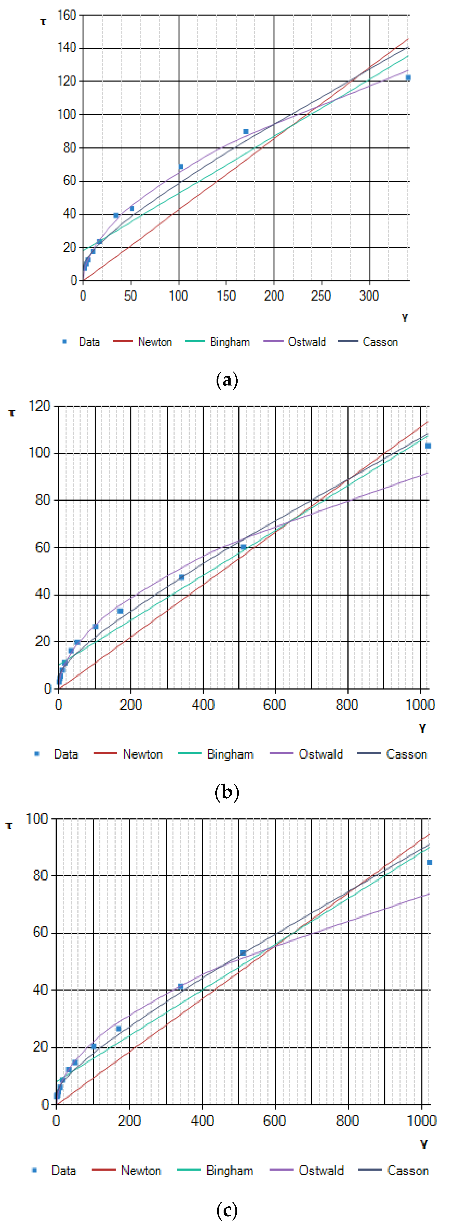
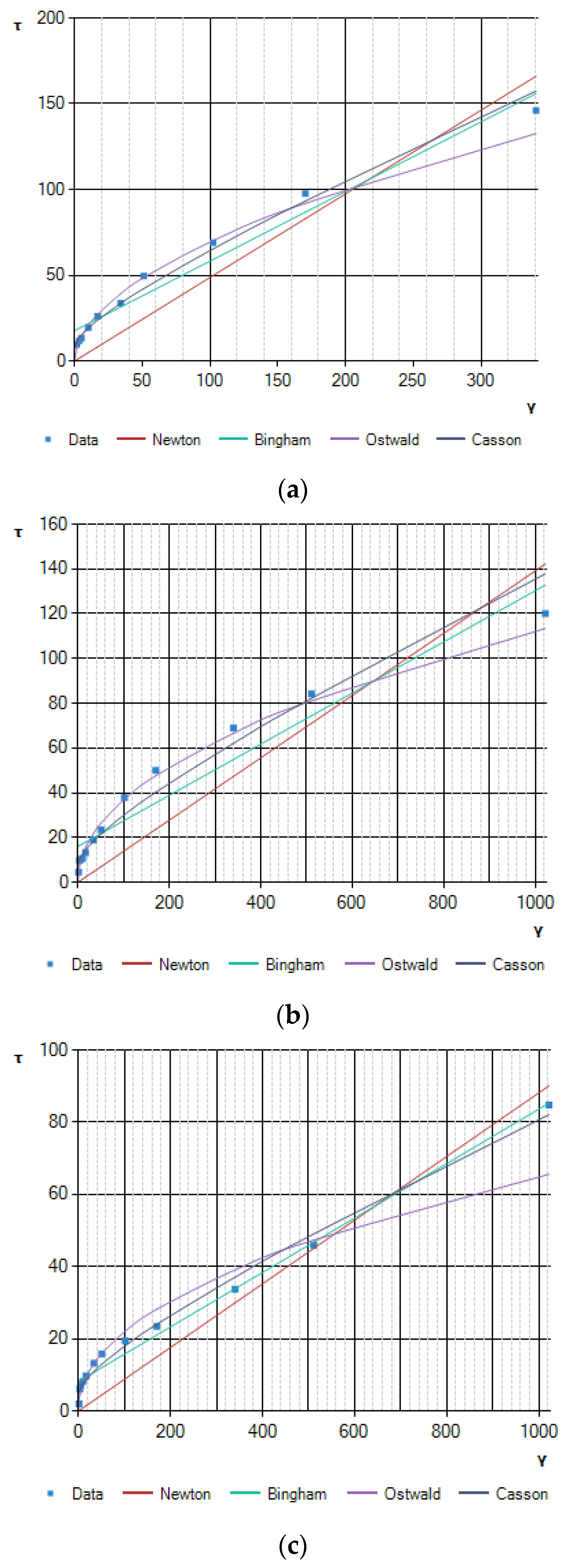
  • Determination of the rheological model—the selection of the optimal rheological model of cement slurries consists in determining the rheological curve that enables the best description of the measurement results in the coordinate system: shear stress (τ)–shear rate (γ).
In order to facilitate the calculations related to the determination of optimal rheological models for the tested slurries, the computer program “Rheo Solution” was used. This program is owned by the Department of Drilling and Geoengineering at the Faculty of Drilling, Oil and Gas, AGH University of Science and Technology.
(b)
For hardened cement slurries compounds:
  • Compressive and bending strength—using a testing machine—model E183 PN by Matest.
The machine used was used to test samples of hardened cement slurry with dimensions of 40 × 40 × 160 mm. It had two test chambers, one for beam fracture testing and the other for sample compression. It had automatic control of the increase in force (kN/s) depending on the expected compressive strength. The test range was 15 kN for breaking and 250 kN for compressive.

3. Results and Discussion

The influence of the water–cement coefficient on the technological parameters of fresh cement slurries prepared on the basis of CEM V/A multi-component cement in varieties A and B is presented in Table 2, Table 3, Table 4 and Table 5.
The density of the cement slurries decreased with increasing w/c ratio. Ash content in the cement (variant B) also affected this parameter. The research shows that slurries based on cement A had a higher density than slurries made on cement B (30% ash), i.e., an increase in the ash content in cement caused a decrease in its density, while an increase in the concentration of ground granulated blast furnace slag (24.6% in variant A) increased its density.
The value of the water–cement coefficient in the slurry also had a significant impact on the amount of sedimentation. Thus, it can be concluded that the higher the w/c ratio, the greater the sedimentation. The slurries prepared on the type A cement had lower sedimentation than the slurries made on the basis of cement B. This effect is related to the different concentrations of the introduced additives. An increase in the concentration of fly ash in cement caused deterioration of the slurry sedimentation properties. The value of the water–cement coefficient in the slurry also had a significant impact on the amount of free water. Thus, it can be concluded that the higher the w/c ratio, the greater the free water. The slurries prepared on the type A cement had lower free water than the slurries made on the basis of cement B. This effect is related to the different concentrations of the introduced additives.
Table 2 shows that the fluidity of the tested cement slurries was directly proportional to the value of the w/c coefficients. The higher the value of the w/c ratio, the greater the fluidity of the slurry. However, taking the mineralogical composition of the tested cements as a criterion, it can be concluded that slurries made on the basis of type A cement (with a higher concentration of ground granulated blast furnace slag) had a greater levelling capacity compared to slurries made on type B cement.
Filtration increased with increasing w/c ratio. The fly ash content also affected this parameter. Slurries made of cement A were characterized by greater filtration than slurries made of cement B.
The water–cement ratio had the greatest impact on the setting time. As its value increased, the bonding time increased. The shortest setting time was characterized by slurries with a w/c coefficient equal to 0.4 (between 2 h and 2 h 30 min), and the longest slurries were characterized by a w/c equal to 0.6 (from 6 h 20 min to 10 h 40 min). The content of silica ash in the cement was also significant. The results presented in Table 3 show that cement slurries made on the basis of type A cement had shorter setting times than slurries made on type B cement.
To calculate cement slurry flow resistance in the process of cementing casing columns in boreholes, parameters calculated for various rheological models (e.g., Newton, Bingham, Casson, Ostwald de Waele) were used. Fitting the mathematical model for the tested grout meant calculating the values of parameters occurring in a given rheological model. Most often, rheological equations describing cement slurries have at least three rheological parameters. The Ostwald de Waele and Casson equations are two-parameter non-linear equations, but they do not take into account the yield stress.
The parameter appearing in the Ostwald de Waele equations is the flow index (𝑛), which classifies the fluid flow, i.e., determines whether the fluid belongs to the category of fluids that are thinned or thickened by shear. Another important parameter of the rheological equations is the yield point (τy), which depends on the consistency of the tested liquid, the distribution and shape of suspended particles (cement grains) and the temperature. It occurs in the Casson equation. Most often, the value of the limiting shear stress (𝜏) is assumed as the value of the flow limit, which is determined during approximation with a given model. Therefore, the actual value may differ from the calculated value.
The rheological parameter appearing in the Ostwald de Waele equation is the coefficient of consistency (k). It depends on the forces of attraction between the particles of the fluid, and therefore on the type and size of the particles of the dispersed phase and the temperature. The coefficient (k) determines the resistance of the fluid to deformation, depending on the shear force.
Using the regression analysis method, rheological parameters were determined for individual models: Newton, Bingham, Casson and Ostwald de Waele. Then, using statistical tests, the best-suited rheological model for a given grout formulation was determined. The best rheological model for each of the analyzed cement slurries was the one characterized by the highest value of the correlation coefficient.
The results of calculations of the rheological parameters for each of the tested cements are presented in Table 4 for type A cement and in Table 5 for type B cement. Based on the values of the correlation coefficients for the analyzed recipes, it was concluded that the best fit of the rheological model in relation to the data obtained from the measurements was the Casson model (variant A), while for cement of the B variety, it was the Ostwald de Waele model.
Figure 1 and Figure 2 show the flow curves in the coordinate system: shear stress (τ)–shear rate (γ) of the tested cement slurries for the analyzed rheological models.
An increase in the w/c ratio, which resulted in a decrease in the concentration of cement in the slurries, improved the rheological properties of each of the slurries tested. These properties were also affected by the percentage of ash in the cement. The calculations presented in Table 4 and Table 5 show that slurries made of cement A were characterized by lower values of plastic viscosity.
The highest viscosity was characterized by the cement slurry with the w/c coefficient equal to 0.4, made on the basis of cement B—0.207 Pa·s, while the slurry with the same w/c, but mixed on the basis of cement A, had a viscosity of 0.188 Pa·s.
Based on the data contained in Table 6, differences in the formation of the flexural strength of the hardened slurries prepared on cements A and B can be seen. As expected, the increase in strength occurred as the maturation time of the seasoned hardened cement slurry samples increased. The water–cement coefficient had the greatest impact on the strength value; increasing the concentration of water in the grout reduced the strength. Slurries based on type A cement had greater strength in relation to the slurry prepared on type B cement. Changes in strength were noticed after 2 days from the moment of slurry preparation. The greatest bending strength was characterized by slurries with a water–cement coefficient of 0.4, made on type A cement. The lowest, on the other hand, was seen for slurries based on type B cement with a w/c equal to 0.6.
Based on the analysis of the results presented in Table 7, it is noted that the water–cement coefficient had the greatest impact on the compressive strength. As the w/c ratio increased, the compressive strength decreased. Ash content in cement also affected strength parameters. Increasing its content caused a slower increase in strength. The highest compressive strength was characterized by slurries with water–cement coefficients equal to 0.4, prepared on the basis of type A cement (from 3.50 to 42.30 MPa). The slurries with w/c equal to 0.6 prepared on cement B (from 0.90 to 13.50 MPa) had the lowest strength.

4. Conclusions

  • The percentage content of the main components (clinker, slag, ash) in multi-component cement has a significant impact on the technological parameters of fresh and hardened cement slurries. The selection of the CEM V cement variety will depend on the geological and technical conditions in which casing columns are cemented in boreholes.
  • Technological parameters of slurries based on multi-component cements can be designed and selected due to the nature of the work performed and the required preferences. They can be applied, among others, to the following:
    • Cementing columns of casing pipes in boreholes;
    • Liquidation of absorptive zones in the subsoil;
    • Hydrotechnical and underground construction;
    • Soil stabilization in road and urban construction;
    • Special geoengineering works (drilled piles, diaphragm walls, displacement piles formed in the ground, micropiles).

Author Contributions

Methodology, S.S. and M.K.; Validation, S.S.; Resources, S.S. and M.K.; Data curation, M.K.; Writing—original draft, S.S.; Writing—review & editing, M.K.; Project administration, S.S. and M.K. All authors have read and agreed to the published version of the manuscript.

Funding

This work was financially supported by the Ministry of Science and Higher Education Warsaw (Internal order Oil and Gas Institute—National Research Institute Project No. 0051/KW/23-INiG-PIB, and 16.16.190.779-WWNiG AGH).

Data Availability Statement

Not applicable.

Acknowledgments

The author thanks the anonymous reviewers for their constructive comments and the editor for handling the paper.

Conflicts of Interest

The author declares no conflict of interest.

References

  1. Gonet, A.; Knez, D.; Macuda, J.; Stryczek, S. Selected Issues of Wellbore Hydraulics and Cementing; Knez, D., Ed.; AGH University of Science and Technology Press: Cracow, Poland, 2017. [Google Scholar]
  2. Gonet, A.; Stryczek, S. Podstawy Geoinżynierii; Wydawnictwa AGH: Cracow, Poland, 2020. [Google Scholar]
  3. Kremieniewski, M. Zaczyny o obniżonej gęstości stosowane w warunkach występowania komplikacji w otworze wiertniczym. Nafta-Gaz 2021, 77, 736–743. [Google Scholar] [CrossRef]
  4. Pisarczyk, S.G. Metody Modyfikacji Podłoża Gruntowego; Oficyna Wydawnicza Politechniki Warszawskiej: Warszawa, Poland, 2005. [Google Scholar]
  5. Stryczek, S.; Gonet, A. Geoinżynieria. Studia; Rozprawy, Monografie 2000 Nr. 71; Polska Akademia Nauk. Instytut Gospodarki Surowcami Mineralnymi i Energią: Cracow, Poland, 2000. [Google Scholar]
  6. Aadnoy, B.S.; Cooper, I.; Miska, S.Z.; Mitchell, R.F. Advanced Drilling and Well Technology; SPE: Richardson, TX, USA, 2009. [Google Scholar]
  7. Kremieniewski, M. Poprawa Stabilności Sedymentacyjnej Zaczynów Cementowych; Prace Naukowe Instytutu Nafty i Gazu Państwowego Instytutu Badawczego: Kraków, Poland, 2017. [Google Scholar]
  8. Kremieniewski, M. Recipe of Lightweight Slurry with High Early Strength of the Resultant Cement Sheath. Energies 2020, 13, 1583. [Google Scholar] [CrossRef] [Green Version]
  9. Kremieniewski, M.; Rzepka, M.; Stryczek, S.; Wiśniowski, R. Comparison of gas migration test and building structural strength of slurry in the aspect of limiting gas invasion. AGH Drilling Oil Gas 2016, 33, 595–608. Available online: http://journals.bg.agh.edu.pl/DRILLING/2016.33.3/drill.2016.33.3.595.pdf (accessed on 15 February 2023). [CrossRef] [Green Version]
  10. Kremieniewski, M.; Wiśniowski, R.; Stryczek, S.; Orłowicz, G. Possibilities of Limiting Migration of Natural Gas in Boreholesin the Context of Laboratory Studies. Energies 2021, 14, 4251. [Google Scholar] [CrossRef]
  11. Stryczek, S.; Gonet, A.; Rzyczniak, M. Technologia Cieczy Wiertniczych; Wydawnictwa AGH: Kraków, Poland, 2018. [Google Scholar]
  12. Stryczek, S.; Małolepszy, J.; Gonet, A.; Wiśniowski, R.; Kotwica, Ł. Wpływ Dodatków Mineralnych Na Kszałtowanie Się Właściwości Technologicznych Zaczynów Uszczelniających Stosowanych W Wiertnictwie I Geoinżynierii; Monografia pod redakcją Stryczka S. Wydawnictwo SCMR Wioska z Chorzowa: Kraków, Poland, 2011; Projekt współfinansowany przez UE w ramach środków Europejskiego Funduszu społecznego—Kapitał Ludzki. [Google Scholar]
  13. Stryczek, S.; Wiśniowski, R.; Gonet, A. Wpływ Plastyfikatorów Na Właściwości Reologiczne Zaczynów Uszczelniających Do Prac Geoinżynieryjnych; Wiertnictwo, Nafta, Gaz; Wydawnictwa AGH: Kraków, Poland, 2007. [Google Scholar]
  14. Stryczek, S.; Wiśniowski, R.; Uliasz-Misiak, B.; Złotkowski, A.; Kotwica, Ł.; Rzepka, M.; Kremieniewski, M. Studia Nad Doborem Zaczynów Uszczelniających W Warunkach Wierceń W Basenie Pomorskim; Stryczek, S., Ed.; Wydawnictwa AGH: Kraków, Poland, 2016. [Google Scholar]
  15. Gonet, A.; Stryczek, S.; Kremieniewski, M. Modern Methods of Strengthening and Sealing Salt Mines. Energies 2022, 15, 5303. [Google Scholar] [CrossRef]
  16. Kurdowski, W. Chemia Cementu I Betonu; Wydawnictwo Naukowe PWN: Warszawa, Poland, 2010. [Google Scholar]
  17. Małolepszy, J. Hydratacja I Własności Spoiwa Żużlowo-Alkalicznego; Wydawnictwa AGH: Kraków, Poland, 1989. [Google Scholar]
  18. Neville, A.M. Właściwości Betonu (Tłumaczenie Z Języka Angielskiego), 5th ed.; Polski Cement: Kraków, Poland, 2012. [Google Scholar]
  19. Izak, P. Reologia Zawiesin Ceramicznych; Wydawnictwa AGH: Kraków, Poland, 2012. [Google Scholar]
  20. Kembłowski, Z. Reometria Płynów Nienewtonowskich; WNT: Warszaw, Poland, 1973. [Google Scholar]
  21. Wiśniowski, R.; Stryczek, S.; Skrzypaszek, K. Kierunki Rozwoju Badań Nad Reologią Płynów Wiertniczych; Wiertnictwo, Nafta, Gaz; AGH: Kraków, Poland, 2007; Volume 24. [Google Scholar]
  22. Wiśniowski, R.; Stryczek, S.; Skrzypaszek, K. Wyznaczanie Oporów Laminarnego Przepływu Zaczynów Cementowych, Opisywanych Modelem Herschela-Bulkleya; Wiertnictwo, Nafta, Gaz; AGH: Kraków, Poland, 2006; Volume 23. [Google Scholar]
  23. Wiśniowski, R. O Oporach Przepływu Cieczy Wiertniczych; Wiertnictwo, Nafta, Gaz; AGH: Kraków, Poland, 2003; Volume 20. [Google Scholar]
  24. Kremieniewski, M.; Błaż, S.; Stryczek, S.; Wiśniowski, R.; Gonet, A. Effect of Cleaning the Annular Space on the Adhesion of the Cement Sheath to the Rock. Energies 2021, 14, 5187. [Google Scholar] [CrossRef]
  25. Kon, E.; Jóźwiak, H. Klasyfikacje i Wymagania Dla Domieszek Do Betonu, Zaprawy i Zaczynu. Cem. Wapno Beton 2000, 5, 23–26. [Google Scholar]
  26. Kucharska, L. Tradycyjne i współczesne domieszki do betonu zmniejszające ilość wody zarobowej. Cem. Wapno Beton 2000, 5, 46–61. [Google Scholar]
  27. Kremieniewski, M. Wpływ wybranych dodatków lekkich na zmianę parametrów technologicznych zaczynu. Nafta-Gaz 2022, 78, 426–434. [Google Scholar] [CrossRef]
  28. Stryczek, S.; Gonet, A.; Kremieniewski, M. Special Cement Slurries for Strengthening Salt Rock Mass. Energies 2022, 15, 6087. [Google Scholar] [CrossRef]
  29. Łukowski, P. Nowe osiągnięcia w dziedzinie domieszek do betonu. Nowocz. Bud. Inżynieryjne 2015, 32–36. [Google Scholar]
  30. Kremieniewski, M. Rola plastyfikatora w projektowaniu zaczynu lekkiego o podwyższonej stabilności sedymentacyjnej. Nafta-Gaz 2019, 75, 571–578. [Google Scholar] [CrossRef]
  31. Łukowski, P. Domieszki upłynniające-osiągnięcia, perspektywy, wyzwania. Bud. Technol. Archit. 2018, 53–56. [Google Scholar]
  32. Kremieniewski, M. Improving the Efficiency of Oil Recovery in Research and Development. Energies 2022, 15, 4488. [Google Scholar] [CrossRef]
  33. Available online: https://www.basf.com/pl/pl.html (accessed on 4 November 2021).
  34. Available online: https://www.master-builders-solutions.com/pl-pl (accessed on 4 November 2021).
  35. Available online: https://www.master-builders-solutions.com/pl-pl/products/masterglenium (accessed on 4 November 2021).
  36. Kremieniewski, M. Korelacja skuteczności działania środków dyspergujących o różnym mechanizmie upłynniania. Nafta-Gaz 2020, 76, 816–826. [Google Scholar] [CrossRef]
  37. Wiśniowski, R.; Skrzypaszek, K. Komputerowe wspomaganie wyznaczania modelu reologicznego cieczy—Program Flow-Fluid Coef. NTTB Nowocz. Tech. I Technol. Bezwykopowe 2001, 2, 72–77. [Google Scholar]
  38. Wiśniowski, R.; Skrzypaszek, K. Analiza modeli reologicznych stosowanych w technologiach inżynierskich. Wiert. Naft. Gaz 2006, 23, 523–532. [Google Scholar]
  39. Kremieniewski, M. Zmiana parametrów reologicznych zaczynu lateksowego pod wpływem dodatku mikrosfery. Nafta-Gaz 2020, 76, 37–45. [Google Scholar] [CrossRef]
Figure 1. Flow curves of cement slurry based on multi-component cement, grade A, with different water–cement coefficients. (a) Water–cement coefficient 0.4. (b) Water–cement coefficient 0.5. (c) Water–cement coefficient 0.6.
Buildings 13 01633 g001
Figure 2. Flow curves of the cement slurry made on the basis of type B multi-component cement with different water–cement coefficients. (a) Water–cement coefficient 0.4. (b) Water–cement coefficient 0.5. (c) Water–cement coefficient 0.6.
Buildings 13 01633 g002
Table 1. The percentage of the main ingredients that made up Recipes A and B.
Cement CEM V/A
according to the
PN-EN 197-1 Standard
CEM V/A Cement Prepared according to Recipe ACEM V/A Cement
Prepared according to Recipe B
Clinker content,
% by weight
40–6453.345.5
Slag content (S),
% by weight
18–3024.621.0
Ash content (V),
% by weight
18–3018.030.0
Set time regulator,
% by weight
0–54.03.5
Table 2. Technological parameters of fresh cement slurry based on CEM V/A cement.
w/c0.40.50.6
Densitykg/m3Cem A187018001690
Cem B183017201640
Free water%Cem A0.000.000.00
Cem B0.000.000.64
FluiditymmCem A110135200
Cem B95120160
Relative viscositysCem A--29.00
Cem B--36.45
FilteringmL/sCem A60/1590/32110/23
Cem B35/1070/22105/26
Table 3. Setting times of the cement slurry based on CEM V/A cement.
w/c0.40.50.6
Start of bindingCem A4 h 40 min5 h 20 min6 h 20 min
Cem B5 h 00 min6 h 50 min7 h 20 min
End of bindingCem A7 h 20 min8 h 30 min10 h 40 min
Cem B8 h 00 min11 h 00 min13 h 00 min
Setting timeCem A2 h 20 min3 h 10 min4 h 20 min
Cem B3 h 00 min4 h 10 min5 h 40 min
Table 4. Rheological parameters of the cement slurry based on CEM V/A cement, variety A, taking into account different models.
w/c0.40.50.6
Rheological model typeBinghamaPlastic viscosity n, Pas0.1880.09510.08
Yield limit t, Pa30.15110.3448.125
Correlation coefficient r,0.9250.9850.9852
Oswalda de WaeleConsistency factor k, Pasn5.5482.4031.962
Exponent n,0.530.5260.524
Correlation coefficient r,0.9860.9910.99
CasonnaPlastic viscosity n, Pas0.1440.0680.059
Yield limit t, Pa11.4254.3153.246
Correlation coefficient r,0.9470.99410.995
Table 5. Rheological parameters of the cement slurry prepared on the basis of CEM V/A cement, variety B, taking into account various models.
w/c0.40.50.6
Rheological model typeBinghamaPlastic viscosity n, Pas0.2070.11430.066
Yield limit t, Pa32.14916.0729.018
Correlation coefficient r,0.9240.9630.986
Oswalda de WaeleConsistency factor k, Pasn6.2073.952.573
Exponent n,0.5210.4850.461
Correlation coefficient r,0.9880.9970.984
CasonnaPlastic viscosity n, Pas0.160.0810.042
Yield limit t, Pa12.0136.8714.511
Correlation coefficient r,0.9450.9810.996
Table 6. Flexural strength of hardened cement slurries based on CEM V/A cement.
w/c0.40.50.6
Flexural strength, MPa1 dayCementA<1.29<1.29<1.29
CementB<1.29<1.29<1.29
2 daysCementA3.602.10<1.29
CementB3.301.95<1.29
7 daysCementA6.704.103.10
CementB5.604.002.40
14 daysCementA7.905.803.90
CementB6.405.203.70
21 daysCementA9.307.205.10
CementB8.806.604.40
28 daysCementA9.908.005.40
CementB9.207.004.60
Table 7. Compressive strength of hardened cement slurries based on CEM V/A cement.
w/c0.40.50.6
Compressive strength, MPa1 dayCementA3.501.800.90
CementB2.901.200.80
2 daysCementA9.704.802.90
CementB9.104.802.70
7 daysCementA22.0011.106.80
CementB20.0010.406.20
14 daysCementA32.7017.0010.00
CementB27.8015.309.60
21 daysCementA39.1022.9014.20
CementB33.9019.6012.90
28 daysCementA42.3025.1015.50
CementB35.6021.1013.50
Disclaimer/Publisher’s Note: The statements, opinions and data contained in all publications are solely those of the individual author(s) and contributor(s) and not of MDPI and/or the editor(s). MDPI and/or the editor(s) disclaim responsibility for any injury to people or property resulting from any ideas, methods, instructions or products referred to in the content.

