Article

Optimal Design of a Novel Large-Span Cable-Supported Steel–Concrete Composite Floor System

1
College of Civil Engineering and Architecture, Zhejiang University, Hangzhou 310058, China
2
Center for Balance Architecture, Zhejiang University, Hangzhou 310028, China
3
Architectural Design and Research Institute of Zhejiang University Co., Ltd., Hangzhou 310028, China
4
Key Laboratory of Space Structures of Zhejiang Province, Hangzhou 310058, China
5
Future City Laboratory, Innovation Center of Yangtze River Delta, Zhejiang University, Jiaxing 314100, China
*
Authors to whom correspondence should be addressed.
Buildings 2024, 14(1), 113; https://doi.org/10.3390/buildings14010113
Submission received: 29 November 2023 / Revised: 28 December 2023 / Accepted: 29 December 2023 / Published: 31 December 2023
(This article belongs to the Special Issue Novel Steel and Steel-Concrete Composite Structures)

Abstract

:
This paper optimizes the design of a novel large-span cable-supported steel–concrete composite floor system in a simply supported single-span, single-strut configuration, aiming for cost-effective solutions and minimal steel consumption. The optimization considers various cross-sectional dimensions, adhering to building standards and engineering practices, and is based on a non-linear programming (NLP) algorithm. Parameters of live loads ranging from 2 to 10 kN/m2 and spans from 20 to 100 m are considered. The optimization results show that cable-supported composite floors with a single strut exhibit robust economic feasibility for spans of less than 80 m and live loads under 8 kN/m2. Compared to conventional composite floors with welded I-beams, the cable-supported system offers more cost-effective cross-sections and reduces steel consumption. The savings in economically equivalent steel consumption range from 20% to 60%. Discussion on the area ratio of cables to steel beam in the optimal cross-section reveals that the secondary load-bearing system (i.e., bending of the main beam with an effective span length of L/2) may require more steel in cases of ultra-large spans. Therefore, the economical efficiency of cable-supported composite beams with multiple struts and smaller effective span lengths warrants further exploration in future studies.

1. Introduction

In modern architecture, the application of long-span floor systems plays a crucial role, offering distinct advantages across various building types. These systems are exceptionally advantageous in buildings necessitating expansive, unobstructed areas, such as auditoriums, sports complexes, and commercial spaces [1]. The growing functional demands of modern architecture, particularly for substantial interior spaces, have revealed the limitations of conventional flooring systems. This has prompted structural engineers to explore novel approaches, spurring progress in architectural design. In recent years, innovative solutions in building design and construction have significantly evolved, addressing various challenges such as maximizing space, enhancing energy efficiency, and improving sustainability. Among these advancements, inter-story seismic isolation has emerged as a particularly valuable solution in high-rise buildings. This technique effectively separates sections with different functions and seismic performance requirements, thereby providing a tailored approach to structural integrity [2,3,4]. In tandem with these developments, the design of floor systems has also gained increased attention, especially in taller structures. This impact is becoming more pronounced as the spacing between building columns (i.e., large spans) has increased in recent years. The steel–concrete composite floor, integrating the advantages of both concrete and steel structures, emerges as an innovative structural design method. It not only exhibits lightweight characteristics and excellent seismic performance but also proves effective in reducing construction time and costs. In the context of long-span buildings, the utilization of steel–concrete composite floor systems allows for greater flexibility in interior space and offers a broader range of design possibilities.
Minimizing material usage is a foundational objective in civil engineering, particularly in building structures, with profound implications for structural design, construction processes, cost-effectiveness, and overall sustainability [5]. Cable-supported structures, prioritizing axial behavior while minimizing flexural response, have proven highly effective in achieving this goal. Initially prevalent in bridge engineering, cable-supported structures, such as under-deck cable-stayed bridges and combined cable-stayed bridges, have proven to be two innovative and efficient variations within the cable-stayed bridge category [6]. These structures develop two distinct load paths by integrating under-deck and combined cable-staying systems: the cable-staying system and the beam system [7]. The cable-staying system not only delivers exceptional spanning capacity but also enhances structural rigidity, establishing long-span bridges as exemplars of engineering achievement.
In structural engineering, the evolution of structural design has led to innovative concepts like the cable-supported steel–concrete floor system. The cable-supported steel–concrete composite floor structure utilizes beam string structures to support a concrete slab, with the two components being interconnected through bolted connections, as depicted in Figure 1. This integrated system effectively harnesses the strength and stability of the beam string structures, ensuring solid support for the concrete slabs, thus creating a robust and efficient flooring solution suitable for various applications. Chen et al. [8] introduced a novel prestressed compound steel–concrete roof structure known as the cable-supported concrete roof structure, achieved by combining prestressed steel and concrete slabs. They conducted a comprehensive analysis of its fundamental characteristics. Qiao et al. [9,10,11,12,13] examined the influence of various parameters on the statics and natural vibration characteristics of the cable-supported concrete roof structure. An et al. [14] investigated the static characteristics and human-induced vibrations of the cable-supported steel–concrete composite floor, applying it to a gymnasium featuring a large-span roof. Wu et al. [15] further proposed a cable-supported steel–concrete beam with a CFST cross-section to be used in ultra-large-span composite floors. These studies collectively highlight that cable-supported steel–concrete floor systems are exceptionally efficient mechanically, especially in large-span scenarios. As a prestressed and composite structure, the mechanical properties of the cable-supported steel–concrete floor system are significantly influenced by the construction process phase. Compared to traditional systems, their construction is more complex, demanding intricate calculations and meticulous design considerations.
In the pursuit of an economically efficient design for composite floors, this paper focuses on the optimal design of a novel large-span cable-supported steel–concrete composite floor system. Numerous scholars have employed diverse optimization algorithms. While earlier studies prioritized weight minimization as the primary objective function [16,17,18], the present studies place greater emphasis on cost optimization [19,20,21,22,23]. Poitras et al. [24] utilized the particle swarm optimization algorithm to minimize the total mass or cost while satisfying all design criteria. Kim and Adeli [25] conducted the cost optimization of composite floors using a floating-point genetic algorithm model in plastic design and calculated the total cost function of concrete, steel beams, and shear connectors. Korouzhdeh et al. [26] and Ebid [27] continued the study by comparing various optimization algorithms and indicated that the generalized reduced gradient (GRG) method has rapid convergence ability and performs better in the optimization analysis of composite floors.
To explore the optimal design of large-span steel–concrete composite floors, some researchers have broadened the scope of parameter research. Kravanja and Šilih [28] proposed the optimization model of a composite I-section beam based on non-linear programming (NLP) and mixed-integer NLP. Kravanja and Šilih [29] utilized nonlinear algorithms to optimize and compare the economic performance of welded I-section beam steel–concrete composite floors and steel truss concrete composite floors with spans less than 50 m. The results showed that welded I-beam steel–concrete composite floors with spans less than 50 m met the economic design requirements, and their cross-sectional height was significantly smaller than that of steel truss concrete composite floors. Kavanja et al. [30] compared the optimal design of steel–concrete composite floor structures with spans ranging from 5 to 50 m and subjected to live loads of 2 to 10 kN/m2 using the multi-parameter mixed-integer non-linear programming (MINLP) method, providing recommendations for optimizing composite I-section beam steel floor structures.
To investigate the pattern of steel consumption in steel–concrete composite floors under ultra-large spans, Wu et al. [31] and [15] optimized the design of steel–concrete composite floors with welded I-section beams and corrugated web beams, respectively, considering spans of up to 100 m and live loads of up to 10 kN/m2. The results indicated that the economic viability of traditional I-section beam steel–concrete composite floors can be generally achieved within a span range of 60 m but significantly diminishes when dealing with ultra-large spans. In contrast, the steel–concrete composite floors with corrugated web beams can achieve even larger spans with more economical material usage due to the material savings by using the corrugated steel web [32].
The beam string structure has been employed in large-span composite floor structures to extend the application range of traditional steel–concrete composite floor structures. However, existing research has paid relatively less attention to the optimization design of cable-supported steel–concrete composite floors. The current design method primarily functions as a validation procedure, typically depending on empirical selections for component dimensions, while placing minimal focus on considerations of structural costs [33]. Conversely, this study aims to attain the optimal cross-sectional design of cable-supported steel–concrete composite floors, emphasizing the reduction in steel consumption without compromising structural integrity. It is important to note that the optimization problem is developed primarily from the perspective of economical design. Factors such as construction, maintenance, and labor costs are not included in the evaluation of cost-effectiveness.
In this study, a non-linear programming (NLP) algorithm is utilized to evaluate the economic efficiency of structures characterized by ultra-large spans and significant loads. The study conforms to relevant building standards and incorporates established engineering practices. The optimization objective function is defined as the economically equivalent steel consumption per unit floor area, aiming to explore the economic feasibility and optimization direction for cable-supported steel–concrete composite floors with spans ranging from 20 to 100 m and live loads from 2 to 10 kN/m2. The optimization process thoroughly accounts for the varying locations of the plastic neutral axis and the complex constraints related to design. Through the analysis of optimization results, notable achievements encompass the following:
  • The cost-effectiveness and applicability under large span and heavy load conditions for the cable-supported composite floor systems.
  • Optimal cross-sectional characteristics of the steel beams, such as cross-sectional shape and the position of the plastic neutral axis.
  • The superiority of cable-supported composite floors over conventional composite floors with welded I-beams.
Finally, the underlying cause of the economic difference between the studied composite floor systems and the conventional composite floors with welded I-beams/corrugated web beams is analyzed. For ultra-large spans, the development of cable-supported composite beams with single struts may be limited by steel usage in the main beam under bending. Therefore, for spans exceeding 100 m, cable-supported composite floor designs incorporating multiple struts are advised.

2. Optimization Problem

The optimization model is based on a single-span, simply supported cable-supported steel–concrete composite floor, as illustrated in Figure 2. Two design parameters are considered: span (L) and live load (ω) [34]. The span and live load vary uniformly across a range from 20 m to 100 m and from 2 kN/m2 to 10 kN/m2, respectively. Additionally, the self-weight of the structure is regarded as the permanent load within the analysis [35].
The specific parameters include:
(1)
Q355b steel and C35 concrete have been selected as the floor materials due to their common use in engineering [36]. The relevant material properties are provided in Table 1.
(2)
The concrete slab is designed with double-layer two-way reinforcement. The transverse reinforcement ratio and longitudinal reinforcement ratio at the bottom of the slab are set at 0.6% and 0.2%, respectively, in accordance with economic and structural requirements [37]. Furthermore, a two-way reinforcement ratio of 0.2% is also applied at the top of the slab.
(3)
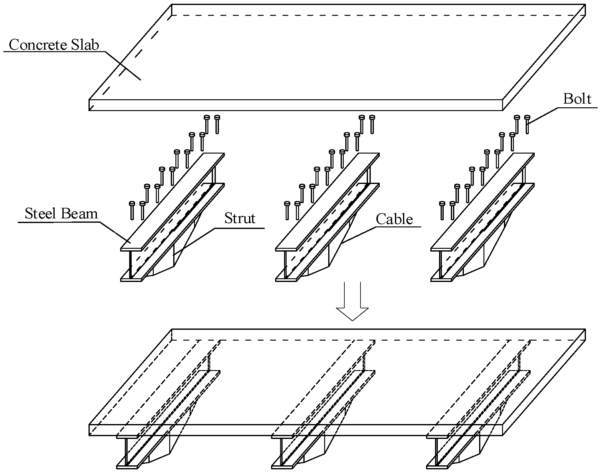
The support rods of the beam string structure utilize circular steel pipe cross-sections, while the cables are constructed using Galfan-coated steel, enhancing their durability and resistance to corrosion. The choice of support rods and cables is based on the component dimensions used at the Heibei Normal University Gymnasium [14,38]. The support rods have a specification of φ159 × 6, while the cables are of 1 × 397 class with a strength grade of 1670 MPa [39].
Table 1. Material properties.
MaterialProperties
Q355b SteelModulus of elasticity (Es)206 GPa
Unit weight (γs)78.5 kN/m3
Design shear strength (fv)205 MPa
Design strength (f)305 MPa
C35 ConcreteModulus of elasticity (Ec)31.5 GPa
Unit weight (γc)25 kN/m3
Design compressive strength(fc)16.7 MPa
The objective function of this study is the economically equivalent steel consumption (W) of cable-supported composite beams under plastic analysis. The formula of W is as follows:
W = γ s A s + α A c + ρ A c + A ca l ca L B
where W is the economically equivalent steel consumption per square meter; As is the cross-sectional area of the steel beam; Ac is the area of the concrete slab; Aca is the cross-sectional area of the cable; lca is the length of the cable; ρ is the total reinforcement ratio of the concrete slab (with a value of 1.2%); α is the ratio of the unit price of concrete to the unit price of steel with equal volume. In this optimization problem, the unit price of concrete is taken as 500 CNY/m3, and the price of steel is taken as 6000 CNY/ton [31].
α = 500   CNY / m 3 6   CNY / kg × 7850   kg / m 3 = 5 471

3. Optimization Process

3.1. Variables

The cross-section of the cable-supported steel–concrete composite beam is depicted in Figure 3, in which the h is the height of the strut. The optimization variables consist of eight parameters: the steel beam spacing (B), the concrete slab thickness (hc), the steel beam flange thickness (hf), the steel beam flange width (bf), the steel beam web height (hw), the steel beam web thickness (tw), the steel cable cross-sectional area (Aca), and the cable sag (hca).

3.2. Assumptions

In accordance with the relevant codes for the design of composite structures [37,40,41,42], the plastic theory analysis is applied to optimize the design of the cable-supported composite beam, relying on the following fundamental assumptions:
(1)
Slip between the concrete slab and the steel beam is neglected to maximize the bending resistance of the cross-section.
(2)
The tensile strength of concrete is not taken into account.
(3)
Concrete in compression is assumed to be uniformly compressed, reaching the design compressive strength.
(4)
The steel beams are designed and analyzed to ensure that different sections of the beams meet the specified design values for steel tensile strength in tension zones and steel compressive strength in compression zones.
(5)
The calculated width of the concrete is determined as follows:
b e = min { L 3 , 12 h c + b f , B }
Analyzing cable impact on the composite beam involves a static analysis with the following assumptions and conditions [43,44,45]:
(1)
The support stiffness of the cable structure is significant enough to be simplified as fixed hinge support for calculation.
(2)
The cable is considered to be ideally flexible and cannot experience compression or bending.
(3)
The material properties of the cable are assumed to follow Hooke’s law.
(4)
Instability issues related to cable-supported composite beam structures are not taken into account in this analysis.

3.3. Constraints

The cable-supported composite beams operate at two distinct load paths. The primary load-bearing system involves a cable-supported structure comprising suspension cables and struts, while the secondary load-bearing system encompasses a beam structure composed of concrete slabs and steel beams with an effective span length of L/2. The cables are modeled according to Hooke’s law, representing their elastic behavior in practical operation. The constraints for the optimization problem of composite beams are primarily based on plastic design theory, incorporating the load transfer mechanism and compliance with relevant engineering standards.
(1)
The primary load-bearing system determines the cross-sectional area of the cables in the cable-supported composite floors. The bearing capacity of the steel cable should meet the following requirement [46]:
N d = q L 4 sin θ A ca f ca γ R
where Nd is the maximum axial tensile force of the cable, fca is the ultimate tensile strength of the cable, and γR is taken as 2.0.
(2)
The ultimate bending moment of the composite beam cross-section is determined by considering half-span composite beams [38]:
M M u
where M represents the mid-span bending moment of a half-span beam under uniformly distributed loads. This moment is determined by the formula: M = 1/32qL2, where q is the design value of the line load, and it is calculated as the combination of live loads and permanent loads (self-weight of the structure), given by q = 1.3 × (γcAc + γsAs) + 1.5 × ωB. Mu represents the design value of the ultimate bending bearing capacity of the section, and its calculation involves specific methods based on the difference in the plastic neutral axis position of the composite beam section [47]. These methods are outlined as follows:
  • When the plastic neutral axis in the concrete slab (As fbe hc fc):
    M u = 2 b f h f f ( h c x c 2 + h f + h w 2 ) + h w t w f ( h c x c 2 + h f + h w 2 )
    where xc is the height of the compressed concrete, given as x c = A s f b e f c .
  • When the plastic neutral axis in the upper flange of the steel beam (As f − 2bf hf fbe hc fc < As f):
    M u = h w t w f ( h f + h w + h c 2 ) + b f h f f ( 2 h f + h w + h c ) 2 b f x f f x f + h c 2
    where xf is the height of the compressed upper flange of the steel beam, given as x f = A s f b e h c f 2 b f f .
  • When the plastic neutral axis in the web of the steel beam (As f − 2bf hf f − 2hw tw fbe hc fc < As f − 2bf hf f):
    M u = b e h c f c ( 2 h f + h w a w + h c 2 ) + b f h f f ( 3 2 h f + h w a w ) x w t w f ( h f + h w x w 2 a w )
    where xw is the height of the compressed web of the steel beam, given as x w = A c h f b f t w , and aw is the distance between the centroid of the section in the tensile zone of the steel beam and the bottom of the steel beam, defined as a w = ( h w x w ) t w ( h w x w 2 + h f ) + 1 2 b f h f 2 A s A c .
(3)
The flange and the web of the steel beam must meet the requirements of the plastic design specifications to achieve the compact steel section for bending and prevent stability issues:
b t w 9 235 f y h w t w 72 235 f y
where b is the extension length of the steel beam flange, defined as b = b f t w 2 .
(4)
The initial pre-stress design of the cable, denoted as σp0, is aimed at counterbalancing the structural deflection resulting from the cable’s self-weight:
σ p 0 = q 0 L 4 A c a sin θ
where θ is the angle between the cable and the composite beam.
(5)
In accordance with engineering practice, the spacing between the steel beams and the thickness of the concrete wing plates in this study are set at the following values:
2.5   m B 6   m 100   mm h c 300   mm }
(6)
The limit on the total height of the cable-supported composite beam in this study is set at:
H = h c a + h 1 L 20
where h1 is the distance from the centroid of the converted section of the composite beam to the top of the concrete slab.

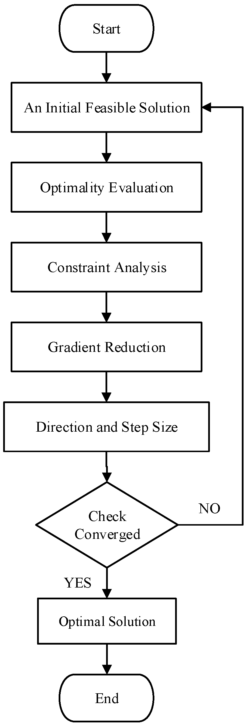
3.4. Optimization Method

To tackle the constructed non-linear programming problem, the generalized reduced gradient (GRG) method is chosen for its efficiency and robustness in solving continuous optimization problems [27,48,49,50]. The GRG algorithm plays a crucial role in transforming the initial constrained optimization problem into a mathematical model with equality and boundary constraints. The core principle involves continuously monitoring the gradient of the objective function as variables evolve, ultimately determining the optimal solution when the partial derivative reaches zero. The flowchart of the GRG optimization method is shown in Figure 4.
For program implementation, the Solver SDK optimization analysis tool in MATLAB was chosen. This versatile tool offers a wide range of planning and solving engines, well-equipped to handle a broad spectrum of nonlinear optimization challenges while adhering to predefined constraints. The principal objective of the program revolves around the minimization of the specified objective function, accomplished through meticulous scrutiny of variable combinations, ultimately providing optimal variable values.
Throughout the optimization process, the position of the plastic neutral axis within the optimal section may vary, resulting in distinct constraint conditions and calculation formulas that determine the positive bending moment bearing capacity. The optimization process is categorized into three scenarios based on the position of the plastic neutral axis within the optimal section: within the concrete slab, within the upper flange section of the steel beam, or within the web section of the steel beam.

4. Optimization Results

4.1. Economically Equivalent Steel Consumption

The economically equivalent steel consumption is depicted in Figure 5a as a three-dimensional surface. This representation illustrates how economically equivalent steel consumption varies with changes in both span and live load. Notably, as both span and live load increase, the economically equivalent steel consumption sharply rises, indicating unfavorable and uneconomical design conditions. The peak of economically equivalent steel consumption is reached when both the span and live load simultaneously attain their maximum values.
To further investigate the impact of span and live load on economically equivalent steel consumption in cable-supported composite beams, we applied projection processing to Figure 5a, generating isolines. These isolines are depicted in Figure 5b. It is evident that isolines exhibit an inward concave shape and become more closely spaced as both span and load values increase. For example, under a live load of 6 kN/m2, the economically equivalent steel consumption corresponds to composite beam spans of 30 m, 57 m, 78 m, and 97 m for steel consumptions of 50 kg/m2, 100 kg/m2, 150 kg/m2, and 200 kg/m2, respectively. In this case, each 50 kg/m2 increase in steel consumption results in a decrement of allowable span by 27 m, 21 m, and 19 m, respectively. Isolines are sparsely distributed for spans of 80 m or less, particularly under a live load of 8 kN/m2 or lower. In such instances, steel consumption remains relatively low, offering favorable structural and economic benefits.
For further analysis, five live load conditions were considered: 2 kN/m2, 4 kN/m2, 6 kN/m2, 8 kN/m2, and 10 kN/m2. Figure 6a illustrates variations in economically equivalent steel consumption concerning the span, revealing a significant upward trend as the beam span increases. Figure 6b provides insights into the relationship between the rate of increase in economically equivalent steel consumption (U) and the span. This curve indicates a gradual rise in the rate of increase in equivalent steel consumption for the cable-supported composite floor as the span increases. Furthermore, the growth rate is influenced by live loads, with larger loads leading to a faster growth rate of equivalent steel consumption.

4.2. Optimal Cross-Sections

For cable-supported composite beams, the cross-sectional design is significantly influenced by two load-bearing systems. The primary load-bearing system of cable-supported composite floors determines the cross-sectional area of the cables, while the secondary load-bearing system dictates the cross-sectional shape of the composite beams. Several rules for optimal composite beam sections emerge from the data obtained under various working conditions:
  • The ratio of the total height to span approaches the limit value.
  • The width-to-thickness and height-to-thickness ratios of the optimal section reach their limit values.
To explore the optimal cross-sectional shape of the steel beam, the ratio of the web area of the optimized section to the total area of the steel beam, denoted as Ra, was considered. The curves depicting the variations in Ra with span were plotted under different conditions, as shown in Figure 7a. The figure illustrates a notable trend—a decrease in the area ratio of the web to the optimal cross-section of the steel beam as the span increases. Beyond 50 m, this ratio stabilizes between 0.6 and 0.7. This suggests that, for larger spans, the proportion of the web area to the steel beam cross-section decreases, contributing to economic efficiency due to the lower contribution of the web to bending bearing capacity compared to the flange. Analyzing the characteristics of optimal sections involves considering the position of the plastic neutral axis. The ratio of the distance between the plastic neutral axis and the interface of concrete and steel beams (with the concrete direction as positive and the steel beam direction as negative) to the total beam height is expressed as Rh. As depicted in Figure 7b, for a composite beam span of 20 m, the neutral axis is located within the concrete slab under live loads of 2 kN/m2 and 4 kN/m2, while under other conditions, it is situated in the steel beam section. Under varying load conditions, the plastic neutral axis gradually shifts towards the center of the steel beam as the span increases. This strategic shift enhances composite beams’ ability to withstand higher bending loads by maximizing their material plastic deformation capacity. Beyond a span of approximately 40 m, the rate of change in the neutral axis position decelerates, stabilizing after reaching 80 m. This suggests that for ultra-large-span composite floors, the optimal cable-supported composite beam sections exhibit stress characteristics similar to conventional steel beams, potentially impacting economic efficiency.

4.3. Discussion on the Economic Benefits of Cable-Supported Composite Floors

In order to comprehensively assess the economic advantages of cable-supported composite beams, a comparative analysis was conducted. This analysis contrasts the economic efficiency of optimal cable-supported composite floors with conventional composite floors under identical span and load conditions, utilizing data extracted from Wu’s paper [31].
Figure 8 presents a comparison of the optimization results for economically equivalent steel consumption in the cable-supported composite floor system and conventional composite floors with welded I-beams. Isolines are drawn to represent every 50 kg/m2 change in the objective function. Each isoline corresponds to multiple design conditions with the same steel consumption. It is evident from the figure that the red isolines exhibit a more pronounced curvature, indicating better economic efficiency at higher spans. This suggests that the cable-supported composite floor system can be widely adopted with reasonable material consumption. The distribution density of isolines further emphasizes the cable-supported system’s competitive edge in terms of economic efficiency. Notably, the red isolines representing the cable-supported composite floor slab exhibit a lower distribution density compared to the blue isolines, indicating a slower overall growth rate in steel consumption. This suggests that the cable-supported composite floor has a competitive edge in terms of economic efficiency over the welded I-beam composite floor. Furthermore, the cost-effectiveness of cable-supported composite floor slabs improves with increasing span. For instance, under a design condition with a live load of 6 kN/m2 and an economically equivalent steel consumption of 100 kg/m2, the economically optimal span for the cable-supported composite floor exceeds that of the I-beam composite floor by 27 m. This difference grows to 133 m when the steel consumption rises to 200 kg/m2, with the cable-supported system allowing spans exceeding 90 m.
In a study conducted by Wu et al. [15], an optimization approach for composite floor systems was proposed, advocating for the integration of corrugated web sections to minimize steel consumption in the web section while ensuring the requisite bearing capacity. However, upon comparing their data with the results presented in this paper, it can be found that composite floors with corrugated web beams are less economical due to higher steel consumption compared to cable-supported composite floors. This difference in economic feasibility can be attributed to the distinctive load-bearing systems employed. For composite floors with corrugated web beams, the steel usage in the beam structure and the bending moment have a linear correlation, but the bending moment and span have a quadratic relationship. In contrast, for cable-supported composite floors, the primary load-bearing system determines a linear relationship between the steel usage and the span. As a result, the cable-supported composite floor system strategically leverages and allocates the benefits of both beam and cable-supported systems. Despite the reduction in overall steel consumption for composite floors with corrugated web beams due to differences in the web area, for ultra-large spans, the cable-supported system emerges as the recommended choice, showcasing its superior economic efficiency.
Furthermore, cable-supported composite floors offer substantial steel-saving advantages when compared to conventional composite floors with welded-I beams. The percentage of steel savings is illustrated in Figure 9. As depicted, the utilization of a cable-supported structure can result in significant steel savings. Particularly for medium- to large-span floors, the steel savings range from 20% to 60%. It is recommended to choose I-beam composite floors for spans less than 30 m, considering both construction and maintenance costs.
The comprehensive analysis of factors influencing the diminished steel usage in cable-supported composite floors is further elucidated. In Figure 10, the variation in the ratio between the cable-supported composite floors and the cross-sectional area of the optimal steel beam in conventional composite floors is presented across different spans and loads. The figure clearly illustrates that the cross-sectional area of the cable-supported composite floors is approximately one-third that of the steel beam in conventional composite floors. This substantial reduction in the cross-sectional area of the steel beam, achieved through the introduction of the cable-supported structure, leads to a significant decrease in steel consumption.
Figure 11 illustrates variations in the cross-sectional sizes of cables, represented by the ratio Rc. This ratio indicates the optimal cross-sectional size of the cables relative to the total cross-sectional area of the composite beams obtained through the optimization program under various working conditions. The figure highlights that cable-supported composite beams with relatively small spans allocate a significant proportion of the cross-sectional area to the cables. This strategic allocation maximizes the cable’s tensile capacity for load bearing, establishing the cable-supported structure as the primary load-bearing system. This shift in the load-bearing mechanism is a key factor in why cable-supported composite beams exhibit higher load-bearing capacities than conventional composite beams. It reflects an optimization strategy that maximizes the efficiency of the cable-supported system. However, with the gradual increase in span length, the ratio of the optimal cable cross-sectional size to the total cross-sectional area of the composite beam decreases and stabilizes.
Based on the constraint in Equation (4), the steel used in the cables (primary load-bearing system) is determined by the load, the height-to-span ratio, and the span length. As the span L increases, the requirements on the cable cross-sectional area increase linearly. However, the amount of steel used for the steel beam cross-section (secondary load-bearing system) is somewhat linearly related to the bending moment of the beam with an effective span length of L/2 due to the support provided by the cable-supported structure. The relationship between the bending moment and the span length is quadratic, leading to a rapid increase in steel usage. As a result, for extremely large spans, cable-supported composite beams with a single strut may have uneconomical steel usage in the main beam cross-section. Therefore, to achieve an economical design of ultra-large-span composite floors (e.g., L > 100 m), it becomes necessary to develop cable-supported composite beams with multiple struts in order to decrease the effective span length of the main beam under bending. In addition, investigating the design criteria for cable-supported composite beams with multiple struts (e.g., under anti-symmetric deformations) should be a focal point in future studies.

5. Conclusions

In this study, the optimization design problem of large-span cable-supported steel–concrete composite floors, considering live load parameters ranging from 2 to 10 kN/m2 and spans up to 100 m, is addressed. The main findings may be summarized as follows:
  • With increasing span and live load of cable-supported composite beams, there is a notable increase in economically equivalent steel consumption. Cable-supported composite floors with a strut exhibit robust economic feasibility for spans of less than 80 m and live loads under 8 kN/m2.
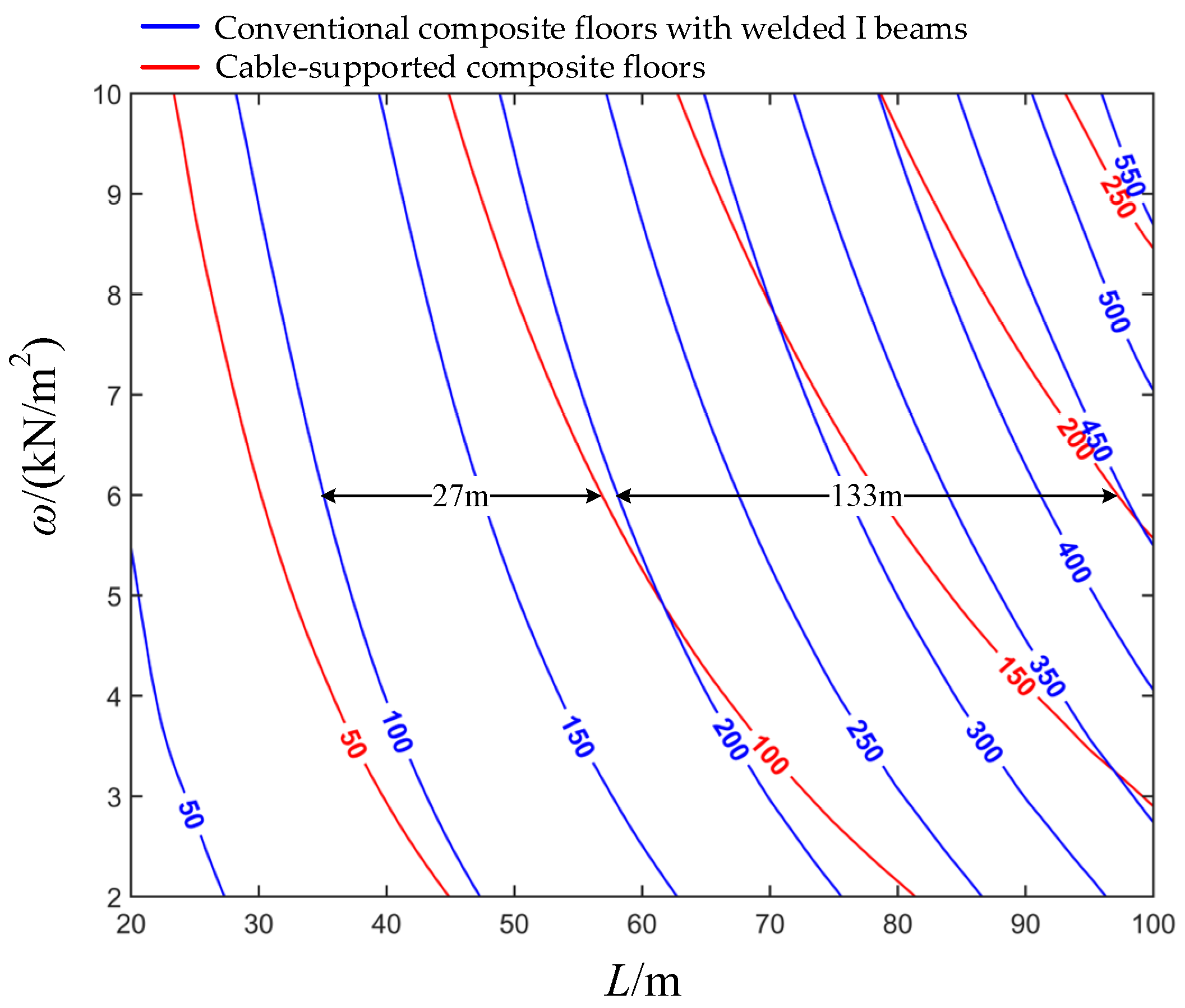
  • A comprehensive comparative analysis was conducted between the cable-supported composite floor and the conventional composite floor, revealing that the cable-supported composite floor system exhibits superior economic efficiency. Especially for medium- to large-span floors, the steel savings range from 20% to 60%. This is because the primary load-bearing system of the cable-supported composite floor is the cable-supported structure, which is more efficient than the single-beam structure under bending.
  • The development of cable-supported composite beams with a single strut for extremely large spans is constrained by the steel usage in the main beam cross-section, due to the beam bending moment associated with an effective span length of L/2 (secondary load-bearing system). Therefore, cable-supported composite beams with multiple struts should be used for ultra-large-span composite floors (e.g., L > 100 m) in order to decrease the effective span length of the main beam under bending.
In order to realize cost-effective design solutions for ultra-large-span composite floors (for example, spans greater than 100 m), the development of cable-supported composite beams with multiple struts becomes crucial. This strategy aims to reduce the effective bending span of the main beam. Moreover, future studies should concentrate on examining the design parameters for such cable-supported composite beams, particularly in scenarios involving anti-symmetric deformations.

Author Contributions

Conceptualization, Y.W. and W.P.; methodology, M.T., W.P. and G.L.; software, M.T., Y.W., W.P. and W.C.; validation, M.T., W.P. and G.L.; formal analysis, M.T. and W.P.; investigation, M.T. and W.P.; resources, Y.W., W.P., G.L. and W.C.; data curation, M.T. and W.P.; writing—original draft preparation, M.T.; writing—review and editing, M.T., W.P., G.L. and W.C.; visualization, M.T.; supervision, Y.W. and W.P.; project administration, Y.W. and W.P.; funding acquisition, W.P. All authors have read and agreed to the published version of the manuscript.

Funding

This research was funded by the National Natural Science Foundation of China (grant no. 52108181) and the Zhejiang Provincial Natural Science Foundation of China (grant no. LQ21E080020). This work was also supported by the Center for Balance Architecture of Zhejiang University (grant no. K20212746).

Data Availability Statement

The data presented in this study are available on request from the corresponding author. The data are not publicly available due to privacy.

Conflicts of Interest

Author Guoming Liu and Wei Chen were employed by the company Architectural Design and Research Institute of Zhejiang University Co., Ltd. The remaining authors declare that the research was conducted in the absence of any commercial or financial relationships that could be construed as a potential conflict of interest.

References

  1. Ahmed, I.M.; Tsavdaridis, K.D. The Evolution of Composite Flooring Systems: Applications, Testing, Modeling, and Eurocode Design Approaches. J. Constr. Steel Res. 2019, 155, 286–300. [Google Scholar] [CrossRef]
  2. Wang, S.J.; Hwang, J.S.; Chang, K.C.; Lin, M.H.; Lee, B.H. Analytical and experimental studies on midstory isolated buildings with modal coupling effect. Earthq. Eng. Struct. Dyn. 2013, 42, 201–219. [Google Scholar] [CrossRef]
  3. Charmpis, D.C.; Komodromos, P.; Phocas, M.C. Optimized earthquake response of multi-storey buildings with seismic isolation at various elevations. Earthq. Eng. Struct. Dyn. 2012, 41, 2289–2310. [Google Scholar] [CrossRef]
  4. Forcellini, D.; Kalfas, K.N. Inter-story seismic isolation for high-rise buildings. Eng. Struct. 2023, 275, 115175. [Google Scholar] [CrossRef]
  5. Chen, Y.; Tong, J.; Li, Q.; Xu, S.; Gao, W.; Liu, X. Flexural Behavior of Novel Profiled Steel-UHTCC Assembled Composite Bridge Decks. J. Constr. Steel Res. 2024, 212, 108258. [Google Scholar] [CrossRef]
  6. Ruiz-Teran, A.; Aparicio, A. Two New Types of Bridges: Under-Deck Cable-Stayed Bridges and Combined Cable-Stayed Bridges—The State of the Art. Can. J. Civ. Eng. 2007, 34, 1003–1015. [Google Scholar] [CrossRef]
  7. Ruiz-Teran, A.; Aparicio, A. Parameters Governing the Response of Under-Deck Cable-Stayed Bridges. Can. J. Civ. Eng. 2007, 34, 1016–1024. [Google Scholar] [CrossRef]
  8. Chen, Z. The State of Art of Cable-Supported Structures. Build. Struct. 2011, 41, 24–31. (In Chinese) [Google Scholar]
  9. Chen, Z.; Qiao, W. Analysis on Basic Characteristics of Cable-Supported Concrete Roof Structure. Build. Struct. 2010, 40, 22–25. (In Chinese) [Google Scholar]
  10. Chen, Z.; Qiao, W. Structural Characteristics Analysis and Parameter Discussion of Cable-Supported Concrete Roof Structure. Build. Struct. 2010, 40, 26–28. (In Chinese) [Google Scholar]
  11. Qiao, W.; An, Q.; Zhao, M.; Wang, D. Experimental Study on the Fundamental Mechanical Features of Cable-Supported Ribbed Beam Composite Slab Structure. Adv. Steel Constr. 2017, 13, 96–116. [Google Scholar]
  12. Qiao, W.; Wang, D.; Zhao, M. Mechanical Features of Cable-Supported Ribbed Beam Composite Slab Structure. Steel Compos. Struct. Int. J. 2017, 25, 523–534. [Google Scholar]
  13. Qiao, W.; Wang, D.; An, Q.; Zhang, H. Study on Dynamic Behaviors and Vibration Reduction Techniques on Cable-Supported Ribbed Beam Composite Slab. Adv. Steel Constr. 2019, 15, 73–81. [Google Scholar]
  14. An, Q. Study on the Mechanical Properties and Human-Induced Vibration of Cable-Supported Composite Floor System. Ph.D. Thesis, Tianjin University, Tianjin, China, 2018. (In Chinese). [Google Scholar]
  15. Wu, Y.; Pan, W.; Luo, Y. Economical Design Comparison of Large-Span Composite Floor Systems with I Beams and Corrugated Web Beams. Buildings 2023, 13, 1940. [Google Scholar] [CrossRef]
  16. Adeli, H.; Kamal, O. Parallel Processing in Structural Engineering; Elsevier Science Publishing Ltd.: Barking, UK, 2003. [Google Scholar]
  17. Adeli, H. Advances in Design Optimization; Chapman & Hall: London, UK, 2002. [Google Scholar]
  18. Vanderplaats, G.N. Numerical Optimization Techniques for Engineering Design: With Applications; McGraw-Hill: New York, NY, USA, 1984. [Google Scholar]
  19. Sarma, K.C.; Adeli, H. Cost Optimization of Concrete Structures. J. Struct. Eng. 1998, 124, 570–578. [Google Scholar] [CrossRef]
  20. Ahmadkhanlou, F.; Adeli, H. Optimum Cost Design of Reinforced Concrete Slabs Using Neural Dynamics Model. Eng. Appl. Artif. Intell. 2005, 18, 65–72. [Google Scholar] [CrossRef]
  21. Sahab, M.; Ashour, A.; Toropov, V. Cost Optimization of Reinforced Concrete Flat Slab Buildings. Eng. Struct. 2005, 27, 313–322. [Google Scholar] [CrossRef]
  22. Kaveh, A.; Shokohi, F. Cost Optimization of Castellated Beams Using Charged System Search Algorithm. Iran. J. Sci. Technol. Trans. Civ. Eng. 2014, 38, 235. [Google Scholar]
  23. Eskandari, H.; Korouzhdeh, T. Cost Optimization and Sensitivity Analysis of Composite Beams. Civ. Eng. J. 2016, 2, 52–62. [Google Scholar] [CrossRef]
  24. Poitras, G.; Lefrançois, G.; Cormier, G. Optimization of Steel Floor Systems Using Particle Swarm Optimization. J. Constr. Steel Res. 2011, 67, 1225–1231. [Google Scholar] [CrossRef]
  25. Kim, H.; Adeli, H. Discrete Cost Optimization of Composite Floors Using a Floating-Point Genetic Algorithm. Eng. Optim. 2001, 33, 485–501. [Google Scholar] [CrossRef]
  26. Korouzhdeh, T.; Eskandari-Naddaf, H.; Gharouni-Nik, M. An Improved Ant Colony Model for Cost Optimization of Composite Beams. Appl. Artif. Intell. 2017, 31, 44–63. [Google Scholar]
  27. Ebid, A.M. Optimum Cross Section and Longitudinal Profile for Unstiffened Fully Composite Steel Beams. Future Eng. J. 2021, 2, 1. [Google Scholar] [CrossRef]
  28. Kravanja, S.; Silih, S. The MINLP Optimization of Composite I-Beams; WIT Press: Southampton, UK, 2001; Volume 54. [Google Scholar]
  29. Kravanja, S.; Šilih, S. Optimization-Based Comparison Between Composite I-Beams and Composite Trusses. J. Constr. Steel Res. 2003, 59, 609–625. [Google Scholar] [CrossRef]
  30. Kravanja, S.; Žula, T.; Klanšek, U. Multi-parametric MINLP Optimization Study of a Composite I-Beam Floor System. Eng. Struct. 2017, 130, 316–335. [Google Scholar] [CrossRef]
  31. Wu, Y.; Pan, W.; Luo, Y. Optimal Design of Long Span Steel-Concrete Composite Floor System. J. ZheJiang Univ. Eng. Sci. 2023, 57, 988–996. (In Chinese) [Google Scholar]
  32. Wu, R.; Wang, L.; Tong, J.; Tong, G.; Gao, W. Elastic Buckling Formulas of Multi-Stiffened Corrugated Steel Plate Shear Walls. Eng. Struct. 2024, 300, 117218. [Google Scholar] [CrossRef]
  33. Yu, C.; Tong, G.; Tong, J.; Zhang, J.; Li, X.; Xu, S. Experimental and Numerical Study on Seismic Performance of L-Shaped Multi-Cellular CFST Frames. J. Constr. Steel Res. 2024, 213, 108360. [Google Scholar] [CrossRef]
  34. Pan, W.; Wang, C.; Zhang, H. Matrix Method for Buckling Analysis of Frames Based on Hencky Bar-Chain Model. Int. J. Struct. Stab. Dyn. 2019, 19, 1950093. [Google Scholar] [CrossRef]
  35. Pan, W.; Wang, C. Elastic In-Plane Buckling of Funicular Arches. Int. J. Struct. Stab. Dyn. 2020, 20, 2041014. [Google Scholar] [CrossRef]
  36. Wu, Z.; Nie, X.; Zhao, J.; Wang, W.; Duan, L. Numerical Study on the Seismic Behavior of Steel–Concrete Composite Frame with Uplift-Restricted and Slip-Permitted (URSP) Connectors. Buildings 2023, 13, 2598. [Google Scholar] [CrossRef]
  37. GB 50010-2010; Code for Design of Concrete Structures. Standardization Administration of the People’s Republic of China: Beijing, China, 2010. (In Chinese)
  38. An, Q.; Chen, Z.; Ren, Q.; Liu, H.; Yan, X. Control of Human-Induced Vibration in an Innovative CSBS–CSCFS. J. Constr. Steel Res. 2015, 115, 359–371. [Google Scholar] [CrossRef]
  39. Xu, F.; Pan, W.; Chan, T.; Sheehan, T.; Gardner, L. Fracture Prediction for Square Hollow Section Braces Under Extremely Low Cycle Fatigue. Thin-Walled Struct. 2022, 171, 108716. [Google Scholar] [CrossRef]
  40. GB 50017-2017; Standard for Design of Steel Structures. Standardization Administration of the People’s Republic of China: Beijing, China, 2017. (In Chinese)
  41. JGJ 138-2016; Code for Design of Composite Structures. Standardization Administration of the People’s Republic of China: Beijing, China, 2016. (In Chinese)
  42. Zhang, H.; Wang, C.; Challamel, N.; Pan, W. Calibration of Eringen’s Small Length Scale Coefficient for Buckling of Circular and Annular Plates via the Hencky Bar-Net Model. Appl. Math. Model. 2020, 78, 399–417. [Google Scholar] [CrossRef]
  43. Tong, J.-Z.; Guo, Y.-L.; Pan, W.-H.; Zhou, P.; Wang, M.-Z. Hysteretic Performance of Inverted-V Patterned BRB Systems Considering Vertical Pre-Compression Effects. Bull. Earthq. Eng. 2019, 17, 3197–3232. [Google Scholar] [CrossRef]
  44. Tong, J.-Z.; Guo, Y.-L.; Pan, W.-H.; Shen, M.-H.; Zhou, P. Global Buckling Prevention of Reduced-Core-Length Buckling-Restrained Braces: Theoretical and Numerical Investigations. Bull. Earthq. Eng. 2020, 18, 1777–1804. [Google Scholar] [CrossRef]
  45. Pan, W.; Tong, J. A New Stiffness-Strength-Relationship-Based Design Approach for Global Buckling Prevention of Buckling-Restrained Braces. Adv. Struct. Eng. 2021, 24, 1343–1356. [Google Scholar] [CrossRef]
  46. JGJ 257-2012; Technical Specification for Cable Structures. Architecture & Building Press: Beijing, China, 2012. (In Chinese)
  47. Du, H.; Yuan, S.; Yu, T.; Hu, X. Experimental and Analytical Investigation on Flexural Behavior of High-Strength Steel-Concrete Composite Beams. Buildings 2023, 13, 902. [Google Scholar] [CrossRef]
  48. Haggag, A. A variant of the generalized reduced gradient algorithm for non-linear programming and its applications. Eur. J. Oper. Res. 1981, 7, 161–168. [Google Scholar] [CrossRef]
  49. Del Castillo, E.; Montgomery, D.C. A nonlinear programming solution to the dual response problem. J. Qual. Technol. 1993, 25, 199–204. [Google Scholar] [CrossRef]
  50. Köksoy, O. A nonlinear programming solution to robust multi-response quality problem. Appl. Math. Comput. 2008, 196, 603–612. [Google Scholar] [CrossRef]
Figure 1. Schematic diagram of the cable-supported steel–concrete composite floor.
Buildings 14 00113 g001
Figure 2. Optimization model of a cable-supported steel–concrete composite floor system.
Buildings 14 00113 g002
Figure 3. Cross-section of the cable-supported steel–concrete composite floor.
Buildings 14 00113 g003
Figure 4. Flowchart of the generalized reduced gradient (GRG) optimization algorithm.
Buildings 14 00113 g004
Figure 5. Economically equivalent steel consumption of cable-supported composite floor. (a) Three-dimensional steel consumption diagram; (b) isolines.
Buildings 14 00113 g005
Figure 6. Variations and trends in economically equivalent steel consumption of cable-supported composite floors. (a) Economically equivalent steel consumption; (b) rate of increase in economically equivalent steel consumption.
Buildings 14 00113 g006
Figure 7. Optimal cross-section properties: (a) the area ratio of the web to the whole section; (b) the relative position of the plastic neutral axis within the whole section.
Buildings 14 00113 g007
Figure 8. Comparison of economically equivalent steel consumption of cable-supported composite floors and conventional composite floors with welded I-beam (unit: kg/m2).
Buildings 14 00113 g008
Figure 9. Steel saving percentage of cable-supported composite floors compared to conventional composite floors.
Buildings 14 00113 g009
Figure 10. The ratio of the cross-sectional area of the steel beam between cable-supported composite floors and optimal conventional composite floors.
Buildings 14 00113 g010
Figure 11. The ratio of the cross-sectional area of the cable to the steel beams.
Buildings 14 00113 g011
Disclaimer/Publisher’s Note: The statements, opinions and data contained in all publications are solely those of the individual author(s) and contributor(s) and not of MDPI and/or the editor(s). MDPI and/or the editor(s) disclaim responsibility for any injury to people or property resulting from any ideas, methods, instructions or products referred to in the content.

