Article

Embroidered Carbon Reinforcement for Concrete †

1
Unit of Concrete Structures and Bridge Design, Department of Structural Engineering and Material Sciences, University of Innsbruck, AT-6020 Innsbruck, Austria
2
Texible GmbH, AT-6845 Hohenems, Austria
3
Faculty of Chemistry and Pharmacy, Research Institute for Textile Chemistry and Textile Physics, University of Innsbruck, AT-6850 Dornbirn, Austria
*
Author to whom correspondence should be addressed.
This article belongs to the Special Issue“Research on the Performance of Non-Metallic Reinforced Concrete”.
Buildings 2023, 13(9), 2293; https://doi.org/10.3390/buildings13092293
Submission received: 11 August 2023 / Revised: 28 August 2023 / Accepted: 1 September 2023 / Published: 8 September 2023
(This article belongs to the Special Issue Research on the Performance of Non-metallic Reinforced Concrete)

Abstract

:
This research focuses on the manufacturing process and mechanical properties of textile reinforcements fabricated using embroidery technology. The study investigates both 2D and 3D reinforcement products and compares the advantages and possibilities of embroidery technology with other manufacturing methods. A series of tests using carbon reinforcement is conducted, and the results are presented and evaluated comprehensively. The uniaxial tensile tests reveal the characteristic behavior of carbon-reinforced concrete (CRC). Furthermore, the bonding behavior between the concrete matrix and embroidered carbon reinforcement is analyzed utilizing asymmetric pull-out tests, demonstrating that the embroidered reinforcements provide a sufficient bond. In addition to conventional 2D reinforcements, 3D reinforcements were also investigated, which can be efficiently manufactured using the TFP (tailored fiber placement) technology. Through the implementation of stirrup rovings, shear failure loads can be increased significantly. The results suggest that the mechanical properties of the reinforcement are influenced by the manufacturing process, which is particularly evident in the variation between longitudinal and transverse directions. The research highlights the potential benefits of using embroidery technology for textile reinforcement and indicates areas for further research and optimization in the manufacturing process. A pilot project that utilizes the embroidered reinforcement is currently under construction.

1. Introduction

The demands of lightweight construction concerning the efficient, resource-saving and responsible use of materials are more in demand today than ever before [1]. In addition, building in existing structures is becoming increasingly important due to ecological and economic aspects in civil engineering and building construction [2]. Increasing aging structures [3], increasing traffic loads and changes in load and dimensioning regulations [4,5,6] are putting a strain on the structures. In addition, the most frequent cause of damage to the common building material reinforced concrete—reinforcement corrosion—is taking its toll [7,8]. In this context, the building material carbon-reinforced concrete (CRC) offers innovative, sustainable and new solutions. Thus, new construction approaches can be realized [9]. Experiments have demonstrated the potential for significant load increases in components by employing non-metallic reinforcement. Furthermore, mechanical models have been developed, yielding congruent results of up to 10% compared to the corresponding experiments [10]. Thereby, the standard reinforcing steel is replaced by fiber materials which, unlike steel, are corrosion-resistant and have significantly higher tensile strengths [11]. The fiber strands used, the so-called rovings, are processed into reinforcement structures using classic production methods from the textile industry. The degree of complexity of such reinforcements ranges from simple, flat 2D textiles to geometrically complex 3D spacer textiles [12]. The vast majority of flat 2D and 3D textile reinforcements for concrete available on the market are produced using so-called warp knitting technology. A multi-ply is produced of parallel rovings in longitudinal and transverse directions which are joined by a knitting thread [13]. Due to the high production rate of this method, reinforcements can be produced relatively cost-efficiently. The stretching of the rovings in the production process results in reinforcements with good mechanical properties [14]. Although it is possible to create such multi-plies with several layers and varying orientations, this production method is in general complex to adapt and is particularly suitable when large quantities of standardized reinforcement have to be produced. For this reason, these reinforcements have a predefined shape, material combination and reinforcement quantity [15]. However, it is important to note that the referenced reinforcement products do not cover externally bonded non-metallic reinforcements, which share a similar application field. An overview and deeper insights into the mechanics of strengthening using these are provided in [16,17,18,19].
Alternatively, adaptive and flexible reinforcement structures can be produced using embroidery technology, specifically through the process of tailored fiber placement (TFP) [20,21,22]. TFP enables the precise placement of fibers along customized paths to create multi-directional structures, resulting in more versatile and adaptable reinforcements. This approach capitalizes on the anisotropic material behavior of fibers, optimizing material usage and presenting an opportunity for cost-effective reinforcement while promoting resource conservation [23,24,25].
The applicability of TFP is not confined to the construction sector; it has already demonstrated its utility in various technical and engineering domains, including aeronautics [26]. Embroidered reinforcements offer elegant solutions to challenges encountered in the structural engineering of carbon-reinforced concrete (CRC) construction.
This paper serves as an introduction and overview of carbon reinforcements produced using technical embroidery. The results are drawn from the authors’ recent research activities to develop carbon reinforcement for strengthening existing structures. A thorough examination of the mechanical properties of selected reinforcements was conducted, involving a comprehensive series of experiments encompassing tension tests, bonding tests, and flexural tests. The manufacturing process underwent optimization based on the obtained results, following an iterative development approach. In this process, mechanical property tests prompted adaptations in the production process, followed by subsequent mechanical property testing and further process adjustments. The objective to utilize this reinforcement for the strengthening of a pilot project was successfully achieved in 2023 [27].

2. Materials

2.1. Fiber Material

Different fiber materials have been used as reinforcement for concrete in civil engineering, most commonly carbon, AR-glass and basalt [28]. As reinforcement in concrete structures, continuous fibers are processed into grids. Analogous to conventional reinforced concrete structures they primarily serve to bear the tensile forces [29]. Due to the mechanical and chemical properties of the non-metallic fiber materials, there are significant differences in design compared to conventional reinforced concrete construction. For example, the tensile strength of carbon fibers is six times higher than that of reinforcing steel. Furthermore, the concrete cover can be reduced to a static minimum due to the corrosion resistance of the fibers. This enables concrete savings of up to 80% [30,31].
After comprehensive investigations and analyses of various fiber materials, such as AR glass, basalt, and carbon, the latter was determined as the most suitable material due to its favorable mechanical [15,32,33,34,35] and durability properties [36,37]. Particularly, the Young’s modulus is several times (approx. 2.5–3) higher than that of basalt and glass fiber. This is particularly intriguing for reinforcement purposes, as the high stiffness allows for a greater transfer of load onto the subsequently applied strengthening layer. Therefore, the embroidered reinforcements are primarily made of carbon. Hence, the investigations in the context of this paper focus solely on carbon reinforcements [24,38].

2.2. Impregnation

Impregnation materials are used to bond the individual fibers of the multi-filament yarn into a load-bearing, more or less solid cross-section. The roving is therefore drenched with an impregnation material. This can be done with different textile finishing techniques, among other coating processes foulard or doctor blade systems have proven suitable [39]. The aim is to create a bond both between the carbon filaments and between the yarn or rod and the concrete matrix [33,40,41]. The main functions of impregnation are to ensure a uniform distribution of tensile stresses in the cross-section of the individual filaments of the roving and to optimize the bond with the hardened cement. The most common materials used are polymers such as acrylates and epoxy resins. [30,34]. Different impregnation materials lead to differences in the mechanical properties and draping capabilities of the textile reinforcements [42,43,44]. The range extends from relatively flexible reinforcements that are available in rolls to rigid grids and molded products [15]. All impregnation materials presented in Table 1 demonstrate high durability properties [45,46,47,48]. Table 1 summarizes the mechanical properties of different types of impregnations and their associated non-metallic carbon reinforcements.

2.3. Concrete

For most of the specimens the high-performance concrete (HPC) TF10 CARBOREFIT® was used. This concrete was specially designed for strengthening with carbon-reinforced concrete according to [50]. Only for the test specimen of the four-point bending tests the HPC Premiumbeton fein® was used. This is a self-compacting concrete with a maximum aggregate size of 4 mm. These concretes’ relatively small maximum grain size ensures that the reinforcement mesh is sufficiently embedded in the matrix.
To determine the material properties for compressive and flexural strength of these special concretes, six prisms were cast at 40 × 40 × 160 mm3. After one day, the specimens were de-molded. One half was stored under water at 20 °C until testing, according to [51], and the other half was cured as the test specimen. They were stored under water until the 7th day and then at 20 °C and 65% relative humidity. The concrete specimens were tested according to [51] on the 28th day. The concrete properties are given in Table 2.

3. Production of Embroidered Reinforcements

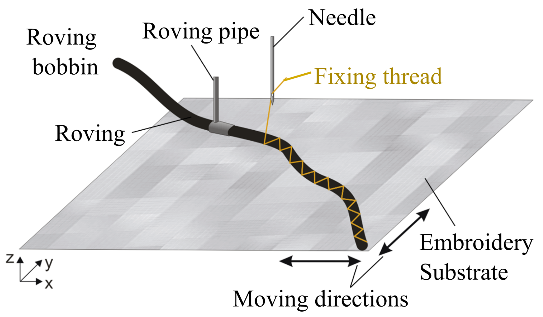
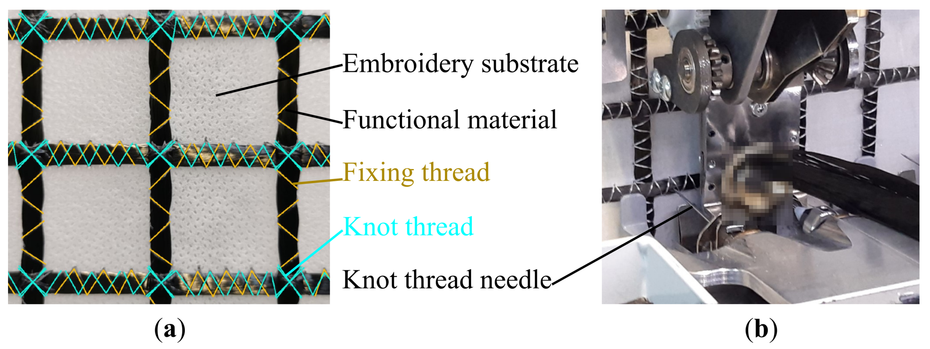
3.1. Embroidery Technology

In principal, embroidery machines work with a frame on which the base material, the so-called embroidery substrate, is stretched. Depending on the function and application, a permanent pattern is applied to it by using threads, whereas needles guide the yarn moving in and out of the embroidery substrate. By increasing the number of embroidery heads, the production time can be shortened [52].

3.2. Tailored Fiber Placement

When using TFP technology, the carbon rovings are sewn onto a flat embroidery substrate by a special machine head. During the fixation of the carbon multi-filament yarn with the fixing thread, it is important to prevent any piercing or damage. The embroidery substrate represents the layer on which embroidery is performed. Depending on the manufacturer, this plane is stretched horizontally or vertically in the area of the embroidery machine. The embroidery substrate can be made from various materials, such as thin wovens or nonwovens or glass fiber fabrics [38]. The desired embroidery pattern is produced by moving the embroidery substrate in a targeted manner. A principal sketch of the TFP process is shown in Figure 1. The input coordinates, which serve as the initiator for the automated movements of the embroidery substrate, are obtained from CAD data. The process of preparing the data for the embroidery machine to interpret is referred to as punching. All possible dimensions of a TFP-manufactured reinforcement structure as well as its production time depend on the available machine infrastructure. The number of available embroidery needles also correlates with the production speed in TFP technology (in comparison to Section 3.1). During the embroidery process, it must be ensured that a temporary anchorage adapted to the embroidery substrate is provided. This is to prevent any displacement of the embroidery design [53].
When using tailored fiber placement, special attention must be paid to the curve radii of the respective embroidery patterns. Among other things, a narrowing in the area of the curve radius can lead to a deviation from the intended path. The thread material used to fix the carbon multi-filaments also has a direct influence on the mechanical properties. If the thread tensions are too high, constrictions can occur in the area of the functional material. This affects the material in subsequent stages of the process negatively [55,56].
When using TFP in comparison to other manufacturing processes, the following potential advantages can be achieved according to [21,57]:
  • Angle-independent deposition of functional material;
  • High positioning accuracy (±0.3 mm with modern CNC-machines);
  • Ability to produce two- and three-dimensional textile semi-finished products with locally variable arrangement of reinforcement threads in the x-, y- and z-directions based on the applied stresses;
  • Prevention of fiber material and matrix accumulations in the final component through the appropriate placement of reinforcement threads specific to the component;
  • Near-net-shape production for material efficiency and waste reduction;
  • Seamless processing of natural, glass, aramid, carbon and ceramic fibers as well as non-textile elements (e.g., optical fibers, metal wire) as functional materials.

3.3. Embroidery Machinery for Carbon Reinforcements

Two different machine types were investigated for the production of flat and curved 2D and 3D reinforcement structures.
  • Multi-head embroidery machine with TFP application
  • Shuttle embroidery machine with soutache application
Regardless the machine type the subsequent reinforcement structure has to be applied to the embroidery substrate in a two-dimensional plane. Thus, it is necessary to position the functional material in such a way that allows it to be arranged into the desired final configuration. This sometimes requires geometric unwinding of the final contour and adherence to a specific embroidery sequence [24,38,58].
When comparing these TFP manufacturing methods to warp knitting technology, it becomes evident that both manufacturing methods offer advantages in specific fields. This is shown in Table 3.

3.4. Process Chain

The process chain begins with rovings threaded onto bobbins as the initial material. The subsequent manufacturing phases are:
  • Formation of planar structures and spatial constructions.
  • Equipment and finishing.
  • Preforming and assembly.
The properties of the embroidered reinforcement are determined by the unique combinations of various process steps and the specific selection of functional material, embroidery substrate, impregnation and fixing thread. The required process steps for production depend on the chosen material selection [24,38].
Although the TFP production process is in principle considered to be direction-independent, certain longitudinal and transverse direction-specific features arise due to the sequence of production steps. When compared with warp knitting technology, the longitudinal direction in TFP corresponds to the warp direction and the transverse direction to the weft direction, considering the subsequent production steps.
The intersection points of the different material layers are then fixed using a separate knotting thread. This is performed with a conventional embroidery needle, whereby the knotting thread is continuously drawn from one knot to the other. The design of the knot itself influences the displacement stiffness of the resulting grid. Furthermore, the repeated sewing of the functional material leads to additional bundling. This increases the uniformity of the cross-sectional shape of the roving [24,38]. A detail of the material placement on the embroidery substrate is given in Figure 2.
Following the fabric-forming process, the embroidery substrate is disintegrated, typically by thermal or chemical processes. As a result, a flexible structure is obtained, which exhibits resistance against displacement and remains connected at the knots. Therefore, the structure can be characterized as a displacement-resistant, open grid with straight rovings, meeting the criteria outlined in [62]. Due to requirements for the use as reinforcement, an impregnation of the fibers is crucial. Suitable materials are given in Section 2.2. The impregnation can be applied using the padder technique, dipping, brushing, or rolling. Throughout the selection of the functional material, suitable impregnation material and appropriate manufacturing process, composite materials can be created that are optimized for use in the construction industry [39]. Epoxy resin impregnations were mainly chosen for their favorable mechanical properties [24,32,38].
During the impregnation curing process, it is essential for the mechanical properties of the final reinforcement that the rovings are in a stretched state. Optimum performance is often achieved by applying tensile forces to the rovings in the longitudinal direction. This can be accomplished using frames or tensioning systems incorporated within the machinery. In the case of curved forms of reinforcement, the impregnated textile structure must be brought into its final position with formworks, molds, or other suitable aids [63].
Three-dimensional reinforcements consist of at least two planes of parallel reinforcement connected by a spatial structure. For this publication, three-dimensional reinforcements are reinforcements that have a third direction of force transmission and therefore also have a functional material in the third spatial direction. They contrast reinforcements in which these structures act only as spacers [64].
The third spatial direction is looped alternately around two rovings of the lower and upper reinforcement layers, forming a sort of stirrup that is similar to the stirrups used in reinforced concrete construction. Due to the production principle of the embroidery, the 3D structure has to be created by unfolding out of the plane. To enable out-of-plane folding, it may be necessary to consider a specific embroidery sequence and placement of the embroidery knots [58].

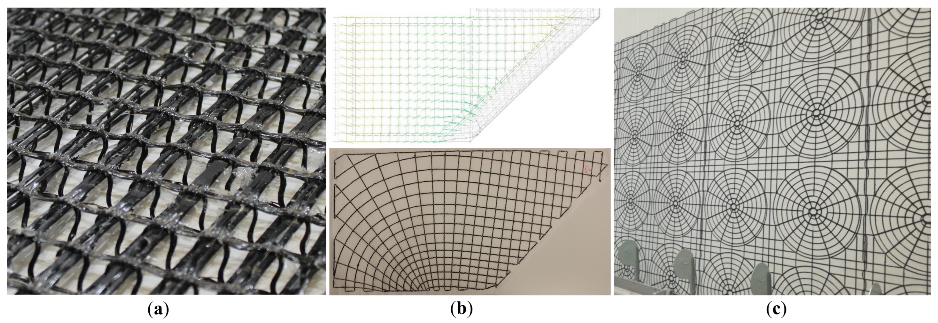
3.5. Selected Reinforcement Examples

The manufacturing of embroidered reinforcement is primarily aimed at leveraging the advantages of embroidery technology. The possibility to position rovings unrestrictedly, thus offering greater flexibility and adaptability, allows the reinforcement to be oriented according to the principal stress directions of the component [24,38]. The possibility of placing rovings in curves could also be used for additional reinforcement for precast elements. Special inlays were produced for areas of concentrated loads. Using TFP technology, the circular reinforcing elements could be produced economically [24,38]. Examples can be seen in Figure 3.
Further investigations on embroidered reinforcements, accounting for the effects on the durability of CRC, can be found in [65]. In pilot projects, the first reinforcement batches of plane reinforcement grids were used. The Krumbach Bridge (47 ° 16 59.9 N 9 ° 53 24.4 E) serves as an illustrative example to showcase the application of embroidered carbon fiber reinforcement, covering a total surface area of 6600 m² and weighing approximately 2500 kg. This marks the inaugural installation of such carbon fiber reinforcements. The carbon fiber reinforcements were used as structural reinforcement to compensate for the existing shear force and torsional deficiencies. Due to the complexity of this pilot project, further publications are referred as follows [27,66,67,68].

3.6. TFP Reinforcements for Test Specimen

All reinforcements used for the investigations consisted of carbon fiber and were impregnated with epoxy resin. The different types of reinforcement grids are given in Table 4. The 3D reinforcement can be seen in Figure 3a.

4. Experimental Investigations

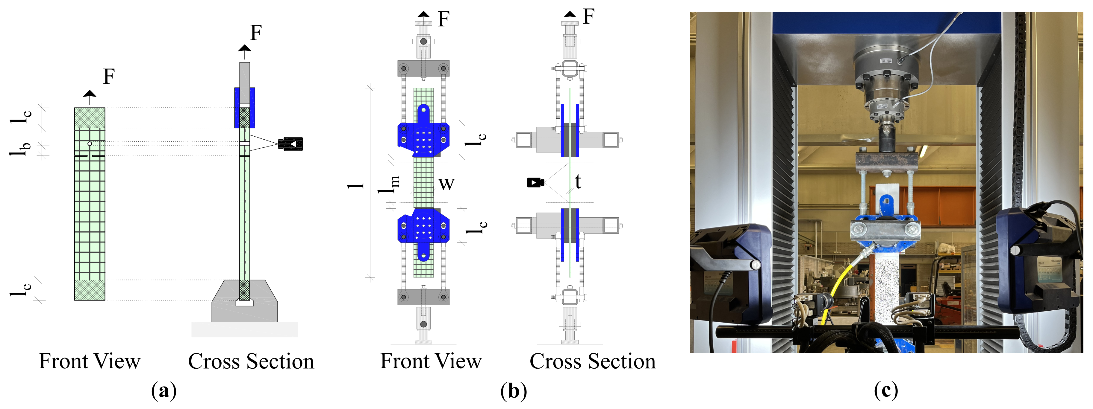
4.1. Uniaxial Tensile Tests

The tensile strength of the reinforcement is a crucial mechanical property and is determined through a uniaxial tensile test. Several test setups have been previously developed for this purpose. The roving stress tests were performed according to [69,70]. Therefore, the roving endings were embedded in epoxy resin to allow clamping. The strain was measured using a video extensometer. The load was applied in a displacement-controlled manner until failure.
In addition to the bare reinforcement test, uniaxial tensile tests were also conducted on CRC specimens. These tests were carried out following [71,72,73,74]. For crack detection and elongation measurement, a photogrammetric system was used. Once again, the load was applied in a displacement-controlled manner. The test setup can be seen in Figure 4.

4.2. Pull-Out Tests

The test setup to determine the bond behavior of the reinforcement was based on the asymmetric pull-out test according to [71,72,75]. Single-layer reinforcement grids with an odd number of at least three rovings are usually used for the specimen. It is crucial to ensure that the reinforcement is aligned centrally within the specimen’s thickness. To create a predetermined location for the crack, the specimen is notched from both sides perpendicular to the direction of loading. When cutting, care is taken to ensure that the lateral rovings are cut through. In order to obtain a defined anchorage length, the middle roving is cut by drilling or cutting. For load application, the specimen is clamped at the ends. Subsequently, a path-controlled tensile force is applied to the specimen. A crack is formed at the notch and the roving is pulled out of the concrete matrix. The test setup is shown in Figure 4b. A specimen thickness t of 20 mm was chosen to provide a concrete cover of 10 mm on each side. The bonding length l b of the central roving was determined based on the axial spacing of the reinforcement grid and was found to range between 27–29 mm.

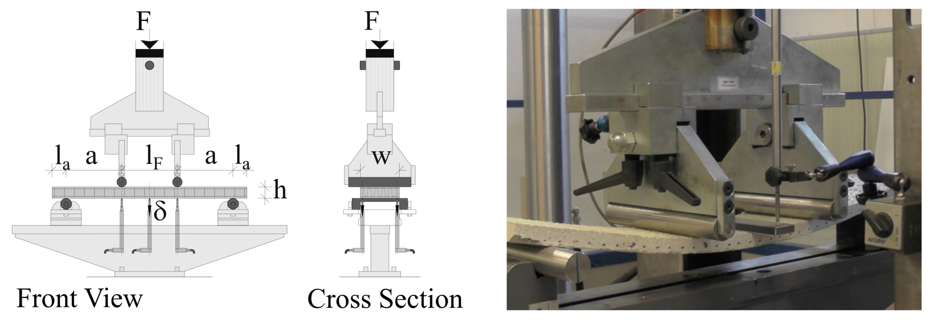
4.3. Four-Point Bending Tests

To demonstrate the effectiveness of the three-dimensional (3D) reinforcements, four-point bending tests were performed. Thus, Reference specimens with two planar (2D) reinforcement grids were compared with the 3D reinforcement. The fineness of the longitudinal rovings was consistent at 3200 tex for all specimens. However, two different heights of reinforcement were used: 20 mm and 31 mm, resulting in specimen thicknesses of 30 mm and 41 mm, respectively. The fineness of the stirrup rovings varied between 800 tex and 1600 tex. The test setup is depicted in Figure 5. As detailed in Section 3.1, the stirrup rovings alternately enclose two longitudinal rovings of the lower and upper layers. The specimen tests are given in Table 5.
As a second parameter, the shear-span-to-effective-depth ratio (a/d) was varied. This parameter defines the portion of the applied force that is transmitted directly to the support via transverse force and is therefore likely to cause shear failure, as well as the portion that contributes to the development of a bending moment. The a/d ratio is also given in Table 5.
Other parameters, such as the load span (lF = 200 mm), width (w = 140 mm), fine concrete mix, impregnation of the carbon rovings and the embroidery sequence, were identical for all specimens. As concrete, the Premiumbeton fein® was used.

5. Results

The results are given for each test setup individually.

5.1. Uniaxial Tensile Tests: Carbon Rovings

The results of the roving tensile tests on the reinforcement 2D-6400 in both the longitudinal (L) and transverse (T) directions are shown in Figure 6 as stress–strain diagrams. The stress–strain diagram depicts a linear-elastic material response until failure.
In the longitudinal direction, a mean value of 3595 MPa is achieved with a number of 10 individual samples. The resulting mean Young’s modulus is 226 GPa. This is calculated as follows according to [25]:
E f , n m , m = 0.9 E f , n m , m 0.1 E f , n m , m 0.9 ϵ f , n m , m 0.1 ϵ f , n m , m
The mean value of the fracture stress of the transverse layer, which also contains 10 individual samples, is 2681 MPa. The resulting Young’s modulus is 203 GPa.

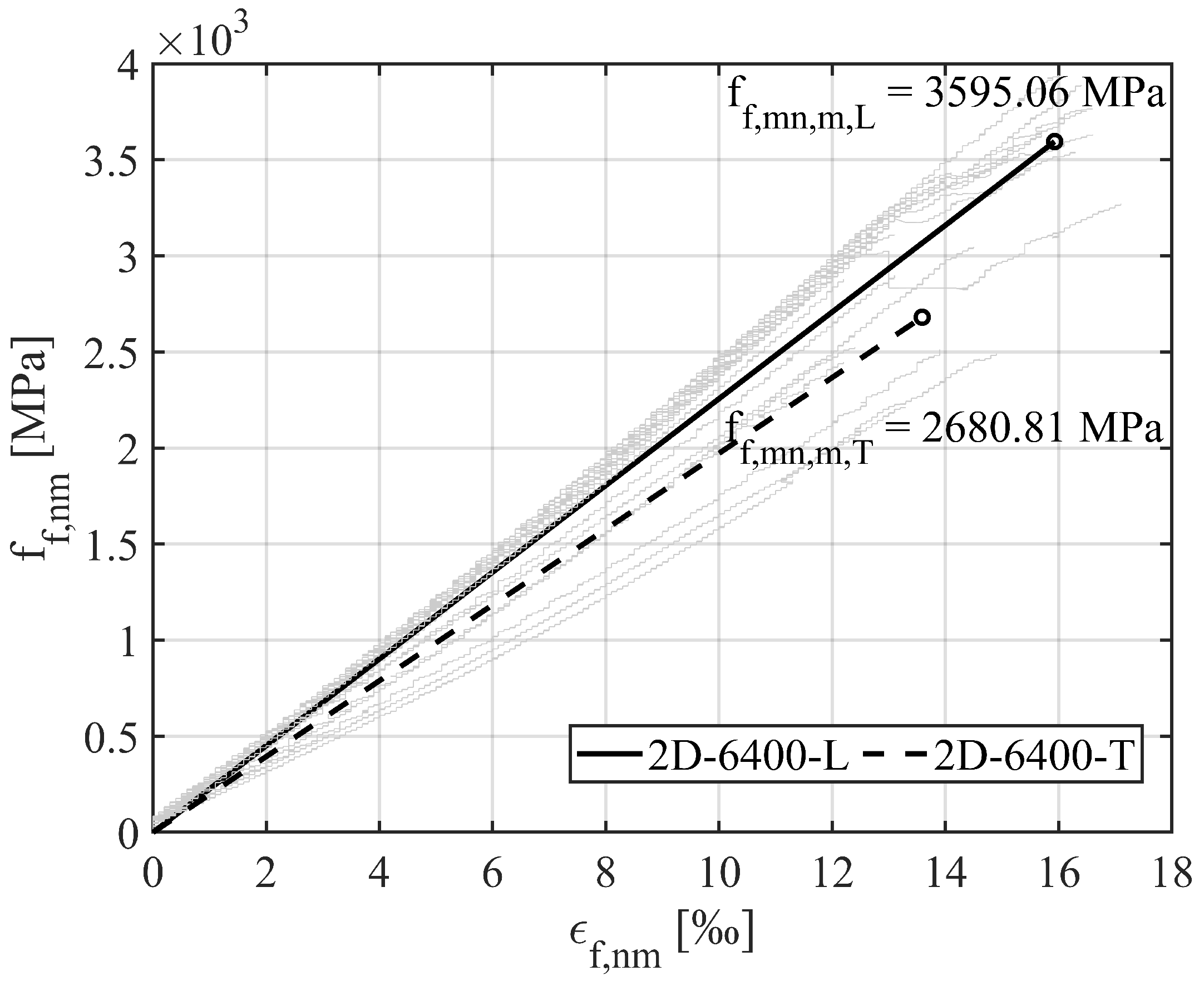
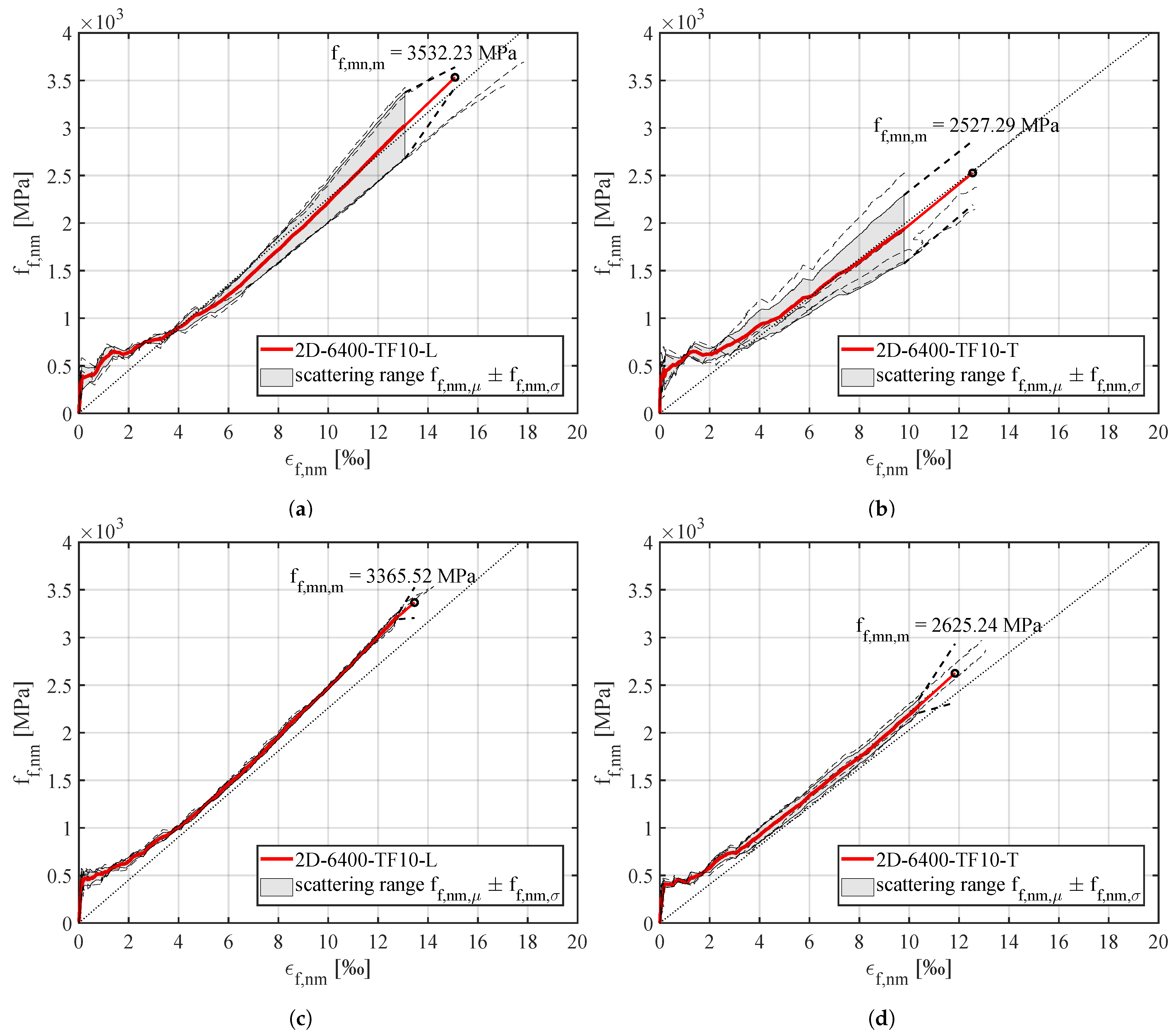
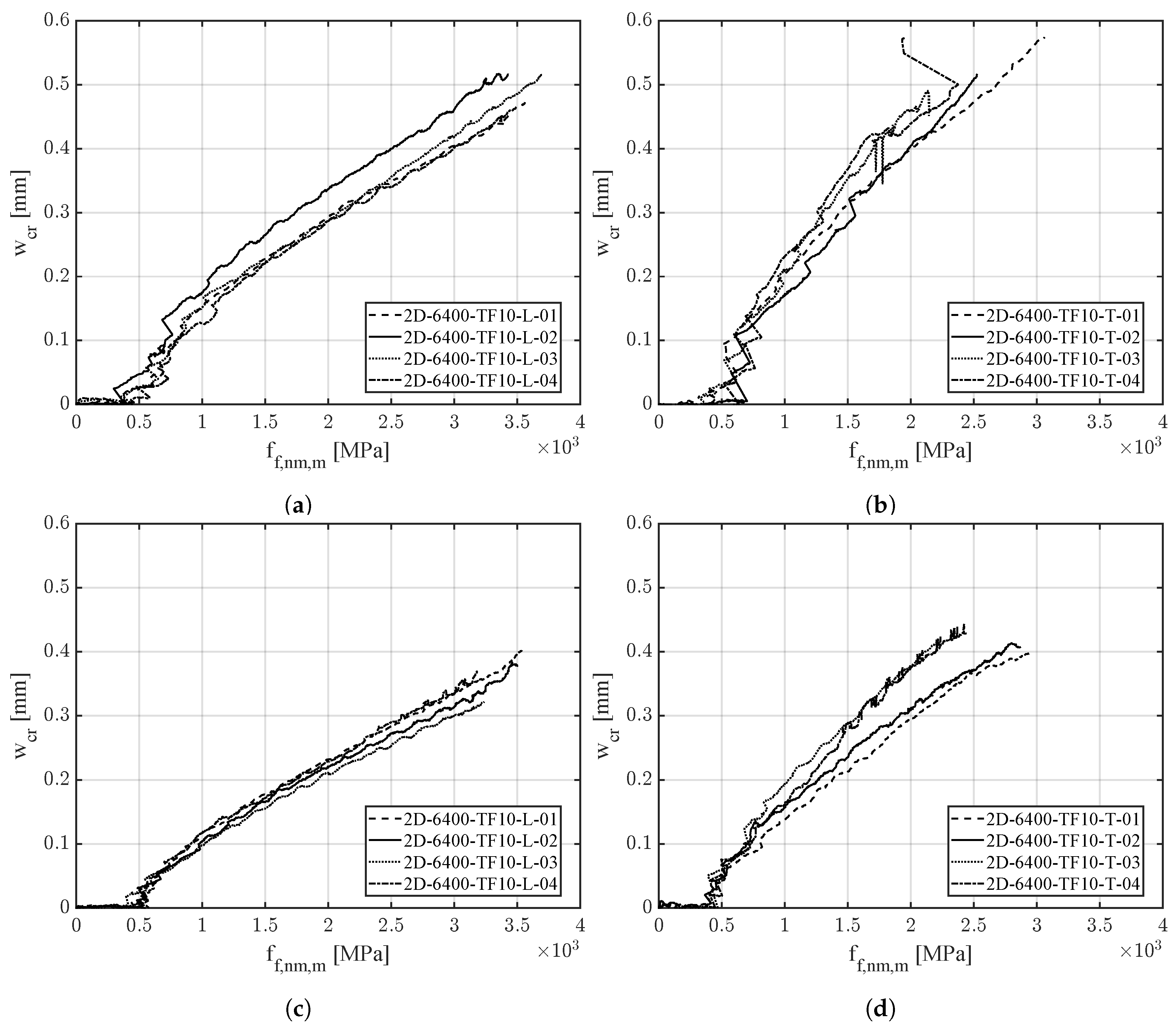
5.2. Uniaxial Tensile Tests CRC
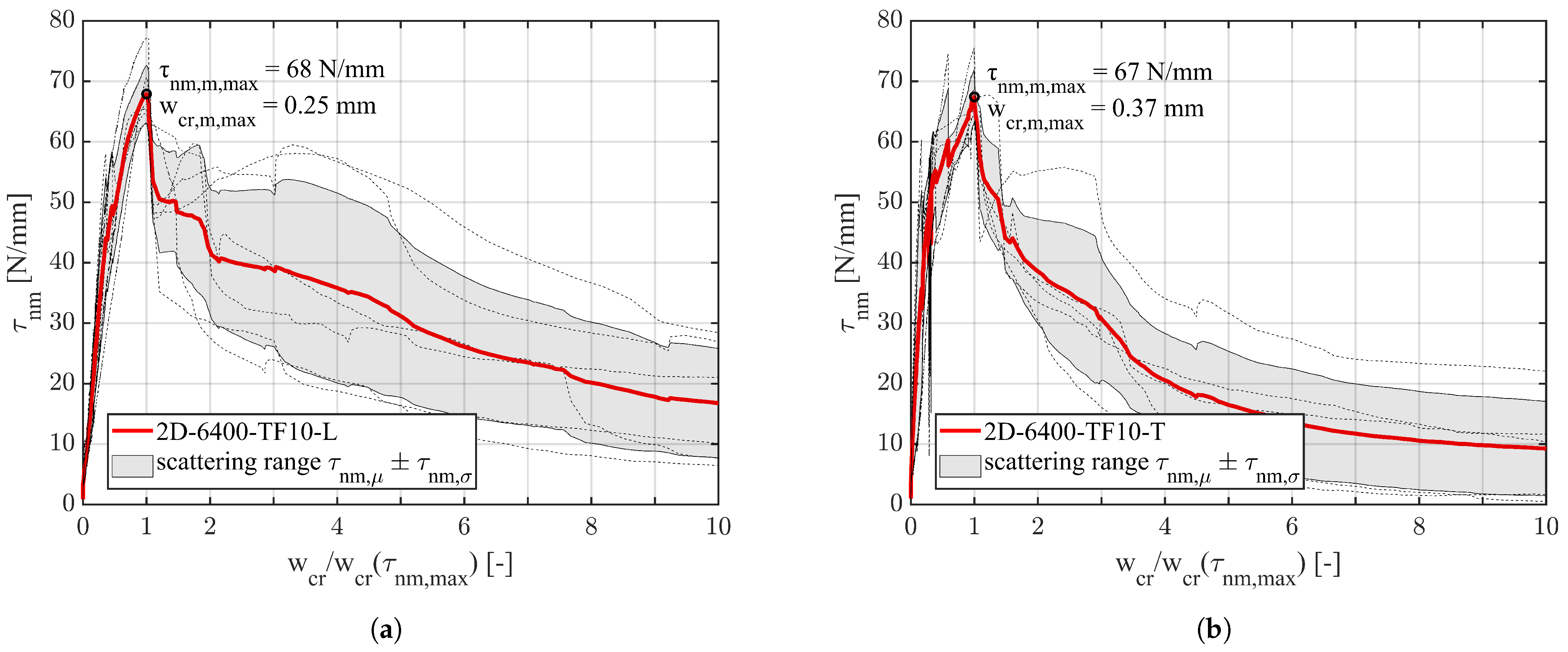
The specimen of the uniaxial tensile tests had different thicknesses depending on the number of reinforcement layers. For specimens with a single layer of reinforcement, the thickness was 20 mm (four rovings each). In the case of specimens with two layers of reinforcement, the thickness was increased to 30 mm (eight rovings each), resulting in two different reinforcement ratios. To ensure uniaxial stresses and eliminate bending moments during testing, the reinforcement was aligned centrally or symmetrically. The concreting was carried out using the laminating method. To be able to describe the samples uniformly and to generate an analogous representation as in the uniaxial roving tensile tests, the stress in the individual rovings is calculated. This is calculated according to Equation (2):
f f , n m = F r e d A f , n m
The experiments were carried out according to the procedure described in Section 4.1. The effect of the CRC composite on the tensile strength of the reinforcement f f , n m , m is determined by measuring the maximum force while considering the total area of reinforcement of the specimen. Specimens with a single layer of reinforcement reached a mean value for maximum tensile strength f f , n m , m of 2520 MPa in the transverse direction and 3530 MPa in the longitudinal direction. The stress–strain diagram is shown in Figure 7a,b. The two-layer reinforced specimens were evaluated in the same manner, and the corresponding results are presented in Figure 7c,d. A mean tensile strength of 2625 MPa was obtained for the transverse direction and 3365 MPa for the longitudinal direction. Three different failure mechanisms could be observed. Failure occurred due to roving rupture (mode α), delamination of the concrete matrix (mode β) and pull-out failure of reinforcement (mode γ). The dotted lines in the diagram describe the respective Young’s module of the reinforcements used in the loading direction and are obtained from the uniaxial roving tests in Section 5.1. An overview of the single test results is given in Table 6.
During the elongation tests, crack development was monitored using a photogrammetric measurement system. The measurement field was consistent for all samples, with a height of 200 mm (along the stress direction) and spanning the entire width of each specimen (108 mm). Figure 8 displays the mean value of the crack width as a function of the roving tension. Specifically, Figure 8a,b represent specimens with a single layer of reinforcement, while c and d represent specimens with two layers of reinforcement.
In general, each specimen developed between 5 and 9 cracks within the measuring range. For the specimens with longitudinal rovings, the averaged maximum crack width is 0.4 mm and 0.51 mm at axial tensile stresses of 3500 MPa and 3600 MPa, respectively. The corresponding values for the transverse rovings were slightly lower, with mean stresses in the reinforcement of 3000 MPa and 3100 MPa, resulting in average maximum crack widths of 0.4 mm and 0.59 mm, respectively.

5.3. Pull-Out Tests

The shear flow was measured in an asymmetrical pull-out test, as described in Section 4.2. To calculate the shear flow, the measured force is divided by the anchorage length which, varies between 27 mm and 29 mm. It is assumed, that the shear flow remains constant over the entire anchorage length.
In addition to the force, the crack width in the area of the notch was measured. In Figure 9, the shear flow is displayed as a function of the crack width, which was normalized by dividing with the crack width at the maximum shear flow. Thus, the maximum value for each specimen can be determined at x = 1 and then statistically evaluated. Each series comprised ten individual samples. Because for each sample the shear flow is assumed to be constant along the anchoring length, it is determined according to the following equation:
τ n m = F r e d l b
The averaged maximum shear flow for longitudinal rovings is 68 N/mm at a mean crack width of 0.25 mm. For the transverse direction, a peak value of 67 N/mm is measured. The associated crack width is 0.37 mm.

5.4. Four-Point Bending Tests

The results obtained from the four-point bending tests are illustrated in the moment-deflection diagram presented in Figure 10. The transverse force is also indicated on the second y-axis. For specimens with a height of 41 mm, the average of three individual tests is depicted, while for specimens with a height of 30 mm, single test results are shown. In the reference specimens, shear failure was observed. However, the inclusion of stirrup rovings prevented this failure when the shear span to effective depth ratio (a/d) was greater than or equal to 5.0, leading to an additional increase in load-carrying capacity until flexural failure occurred due to tearing of the rovings on the tension side. This underscores the effectiveness of the stirrup rovings in preventing shear failure.
For specimens with an a/d ratio of less than or equal to 4.24, shear failure was also observed in cases of 3D reinforcement, albeit at a higher load level. This further demonstrates the positive impact of the stirrup rovings. Depending on the a/d ratio, the load-bearing capacity was enhanced by 33% to 57%.

6. Discussion

The tests presented in this study provide a clear understanding of the mechanical properties of embroidered carbon reinforcements for concrete. The results are interpreted in detail in the following sections.

6.1. Uniaxial Tensile Tests Carbon Rovings

In Figure 6 can be seen that the transverse direction has lower mechanical properties than the longitudinal direction. A comparison of the results of the uniaxial roving tensile tests with the pure fiber material carbon (fnm,u = 4300 MPa) shows that the fiber strength can be utilized to approx. 84% in the longitudinal direction and to approx. 62% in the transverse direction. The problem arises from the need to transfer the fabric between the embroidery and finishing stages, making it difficult to maintain consistent roving tension. This issue is rooted in the non-uniform process flow between fabric production and subsequent steps like impregnation, drying and curing. In the currently used so-called “offline process”, the fabric undergoes local modifications and reorientation on a separate tensioning frame. As a consequence, the yarns are not adequately stretched in the transverse direction, resulting in uneven mechanical properties. This irregularity has an adverse effect on the reinforcing capabilities, in this case, particularly in the transverse direction [15].
The achievable ultimate stress in the transverse direction is approximately 75% and the Young’s modulus is about 90% of the longitudinal direction. It is also particularly striking that the transverse rovings had a significantly higher experimental dispersion. This behavior could also be observed at the beginning of the production of warp-knitted reinforcements, where the weft direction showed sufficient better mechanical properties than the warp direction [63].
Since the same fiber material and impregnation were used, the reason has to be found in the manufacturing process. Decisive for the mechanical properties of the finished reinforcement, apart from the material properties, is the strain that acts on the rovings during production. Together with the type of binding, in the case of TFP, the fixing and knotting thread highly influences the waviness of the single carbon fibers in the composite and therefore highly affects the mechanical properties [13]. It is evident that in the longitudinal direction, the fibers are aligned straighter compared to the transverse direction. Based on these results, the manufacturing process is adjusted to achieve more uniformity in the mechanical properties in the longitudinal and transverse directions and fully exploit the potential of the carbon fibers. However, it should be noted that a slight degradation in the material properties because of production is common [76].

6.2. Uniaxial Tensile Tests CRC

The tensile tests show the expected characteristic behavior for CRC according to the literature [77]. In Figure 4, a linear elastic behavior until forming of the initial crack can be observed. After the full development of the crack pattern, linear elastic behavior is observed again. A comparison with the reinforcement material, which is also depicted in Figure 4, shows a good concordance. For the specimen with a two-layer reinforcement, a tension-stiffening effect is observed, indicated by the parallel shift between the CRC tensile tests and the roving tensile tests. However, this is not observed in the case of the single-layered specimen.
Again, the mean maximal stresses reached in the transverse direction are significantly lower than in the longitudinal direction. The transverse direction has a strength of about 71% for the single-layered specimen and 78% for the specimen with a double layer of reinforcement compared to the longitudinal direction.
It is also evident that the results of the single-layered specimen show significantly more scatter. This also applies to the comparison between the longitudinal and transverse directions, as shown by the gray shaded scatter area in Figure 4. Again, this behavior can be attributed to the manufacturing process. Thus, the results show that, in the best case, the failure stress reached in CRC tensile tests is equal to the roving tensile stresses. However, in the case of imperfectly stretched transverse rovings, deviations of single CRC test results showed a deviation of up to 19% compared to the mean roving tensile stresses. The mean maximum stress of the CRC samples shows a deviation of up to 5% for the transverse rovings, whereas the maximum deviation in the longitudinal direction is 1%.
While corrosion resistance allows for the relaxation of crack width limitations, certain applications may necessitate adhering to specific crack width restrictions, such as the optical requirement of 0.4 mm [78]. In such cases, to ensure serviceability (SLS) [79], it becomes essential to proportionally decrease the stress within the carbon roving. By way of example, the stresses associated with the crack width wcr = 0.4 mm are given in Table 7 and are based on the figures in Figure 8. As expected, a higher reinforcement ratio leads to a smaller crack width [80] and respectively higher stress at wcr = 0.4 mm.

6.3. Pull-Out Tests

Due to the irregular roving cross-section, the shear flow is used to characterize the bond behavior and to examine the suitability of the embroidered reinforcements for its use in CRC. It can be assumed that the adhesive bond between concrete and reinforcement remains active until reaching the maximum shear flow. Showing the shear flow as a function of the normalized crack width in Figure 9 this relates to the section wcr/wcrnm,max) ≤ 1. After reaching the maximum value, the adhesive bond is destroyed, and the bond strength decreases. Finally, the frictional bond is activated, which, however, is significantly lower. This behavior is consistent with the pull-out behavior found in the literature [75,81].
Due to the mentioned manufacturing-related differences, the transverse direction exhibits a less stiff behavior, which is reflected in a larger mean crack width upon reaching the maximum shear flow. Again the shear flow is influenced by many parameters such as the roving surface and shape, transversal rovings, knot stiffness, impregnation and type and form of fixing a knotting thread [75]. Therefore, the results shown can only be viewed as specific to this type of reinforcement, and no general statement can be made for embroidered reinforcements. Again, an influence of the manufacturing process on the mechanical properties can be observed.

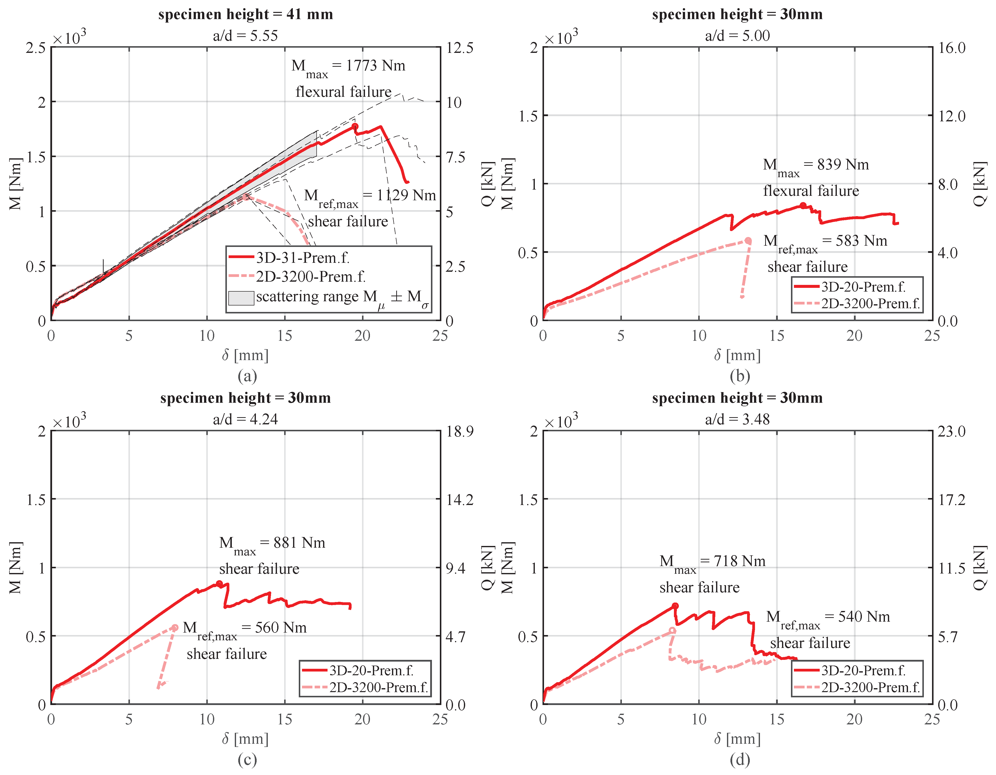
6.4. Four-Point Bending Tests

The range of investigated shear span to effective depth ratio (a/d) reached a maximum value of 5.55 for specimens with a thickness of 30 mm. Surprisingly, despite such slenderness and in consideration of insights from steel-reinforced concrete construction, shear failure occurred in specimens lacking stirrup reinforcements. This defies the conventional expectation of flexural failure [82], yet it aligns with the observations of [63], where this phenomenon was noticed for shear span to effective depth ratios (a/d) of up to 7. According to [83], this could be an effect of the bonding behavior of the textile reinforcement with its substantial longitudinal cracks in the reinforcement layer.
As shown in [84], a non-metallic transverse reinforcement can increase the load bearing of CRC components. This could also be performed by incorporating 3D reinforcements, which notably improved the load-bearing capacity, as demonstrated in Figure 10. The diagram and the corresponding percentage enhancements underscore the efficacy of the reinforcement and its influence on the behavior of the tested specimens. The chart in Figure 10 also illustrates a more ductile response in the specimens, showcasing the advantageous failure indication achieved through the use of textile 3D reinforcements.
For instance, when considering a specimen with a height of 41 mm and an a/d ratio of 5.55, the avoidance of shear failure resulted in tensile stresses of 3230 MPa in the roving, as determined using the iterative method outlined in [63]. This finding suggests that the reinforcement approaches the upper threshold of tensile stress [38]. Although it can already be proven by initial tests that a transverse force reinforcement leads to an increase in load, no decisive statements can yet be made regarding the tensile stresses in the stirrups in the absence of established mechanical models and the limited number of tests.

7. Conclusions

This article describes the manufacturing process of carbon reinforcements using embroidery technology and their 2D and 3D reinforcement products. In addition, the advantages and possibilities compared to other manufacturing methods are described and explained comprehensively. Furthermore, thorough results from a series of tests with carbon reinforcement are presented and evaluated in this article.
  • The results exhibit the excellent mechanical properties of the embroidered carbon reinforcements, making them suitable for use in structural strengthening applications.
  • Based on the analysis from Section 6, it can be concluded that sufficient stretching of the rovings during the finishing process has a crucial influence on their subsequent mechanical properties. This is particularly evident in the evaluation of the roving tensile test data and the evaluation of the uniaxial CRC tensile tests. Rovings in the transverse direction showed a lower average tensile strength and a more significant scattering of the individual results. Thus, there is still a significant potential for optimization and improvement concerning the manufacturing process using embroidery technology. With the current state of knowledge, practical-use reinforcements can already be produced.
  • The results of the asymmetric pull-out tests are presented as a function of the normalized x-axis enabling it to compare the peak values at the same position and to enable an exact statistical evaluation. Based on the results obtained, it can be assumed that a sufficient bond is achieved between the concrete matrix and the embroidered carbon reinforcement. However, it is important to note that the tests were limited to one series with a fixed bonding length between 27 mm to 29 mm according to the considerations from Section 4.2.
  • The maximum load and the deformation of the 3D structure CRC-reinforced specimens increased compared to the 2D structure reference specimens with conventional reinforcement for the four-point bending tests.
  • Due to the small number of specimens, it is not feasible to draw a general conclusion about the load-bearing capacity of the stirrup rovings. As the incorporation of carbon stirrup rovings represents a novel approach, the conducted tests are intended primarily as a proof of concept. Importantly, it is observed that shear failure can be witnessed at a higher shear span to effective depth ratio (a/d) in CRC construction compared to traditional reinforced concrete construction. This phenomenon, coupled with the findings of [63,83,84], suggests either a shift in the shear failure behavior or the presence of ongoing uncertainties in CRC design.
The authors’ further research endeavors entail comprehensive examinations of the bond characteristics of carbon concrete achieved through asymmetric pull-out tests featuring varying anchorage lengths. Additionally, the mechanical performance of reinforcement overlapping joints is going to be investigated. Concurrently, efforts should be dedicated to the further refinement of 3D reinforcements, with particular attention to optimizing the load-bearing behavior of the stirrup rovings and the design models derived from them for the shear force.

Author Contributions

Conceptualization, J.K. and J.W.; methodology, M.E., J.F and T.B.; investigation, J.K., M.E., C.W., T.F. and T.B.; resources, T.F., J.F and T.B.; data curation, J.K., J.W., M.E., C.W. and T.F.; writing—original draft preparation, J.K. and J.W; writing—review and editing, J.F. and T.B.; visualization, J.K. and J.W.; supervision, J.F. and T.B.; project administration, J.K., M.E., J.F. and T.B.; funding acquisition, M.E., C.W., T.F., J.F. and T.B. All authors have read and agreed to the published version of the manuscript.

Funding

This research was funded by Austrian Research Promotion Agency (FFG) grant number 841339 (TEXon), grant number 860474 (TCCV) and 866713 (concreteX).

Data Availability Statement

The data presented in this study are available on request from the corresponding author.

Acknowledgments

The authors express their gratitude to Hämmerle Stickerei, Fussenegger & Grabher and RAC for their support and cooperation. Special thanks are due to the students who were involved in the test implementation in the course of their master’s theses.

Conflicts of Interest

The following authors declare a conflict of interest regarding Patent EP3684985A1: M. Egger, T. Fröis, T. Bechtold, J. Feix. The author T. Fröis is CEO of the company Texible GmbH.

Abbreviations

The following abbreviations are used in this manuscript:
CNCComputerized Numerical Control
CRCCarbon-Reinforced Concrete
FMachine Force
HPCHigh-Performance Concrete
SLSServiceability Limit State
TFPTailored Fiber Placement
ashear span
αfailure mode—roving rupture
a/dratio of shear span to effective depth
A f , n m roving cross-sectional area of the intact fiber strands
Atexreinforcement cross-section
Atexreinforcement cross-section, stirrups
βfailure mode—delamination of the concrete matrix
γfailure mode—pull-out failure reinforcement
δdisplacement
ϵ n m fiber, non-metallic strain
E f , n m , m fiber, non-metallic, mean Young’s modulus roving
E f , n m , m , L fiber, non-metallic, mean Young’s modulus, longitudinal
E f , n m , m , T fiber, non-metallic, mean Young’s modulus, transverse
F r e d machine force, corrected for load application and dead load if required
f c m mean compressive strength of concrete
f c t m , f l mean flexural bending strength of concrete
f f , n m fiber, non-metallic, stress
f f , n m , m fiber, non-metallic, mean tensile stress
f f , n m , μ fiber, non-metallic, mean tensile stress as a function of corresponding strain
f f , n m , m , L fiber, non-metallic, mean tensile stress, longitudinal
f f , n m , m , T fiber, non-metallic, mean tensile stress, transverse
f f , n m , u fiber, non-metallic, rupture stress
f f , n m , σ fiber, non-metallic, standard deviation tensile stress as a function of corresponding strain
F r e d machine force, adjusted for load application and dead load if necessary
hheight
laanchoring length
l b bond length
lcclamping length
lFload span
lmmeasuring length
Mmoment four-point bending test
Mmaxmaximum moment four-point bending test
Mref,maxmaximum moment of the reference specimens four-point bending test
nnumber of roving in the corresponding specimen
Qtransverse force
ρ reinforcement ratio
sHaxial spacing at height
sLaxial spacing in length
sTaxial spacing crossways
tthickness specimen uniaxial tensile tests
texfineness of the reinforcement grams per 1.000 meters
τ n m non-metallic shear-flow
τ n m , μ non-metallic, mean shear-flow as a function of cracking width
τ n m , m , m a x non-metallic, mean, maximum mean shear-flow
τ n m , σ non-metallic, standard deviation shear-flow as a function of cracking width
wwidth
wcrcrack width
wcr,m,maxmaximum mean cracking width

References

  1. Kalthoff, M.; Bosbach, S.; Backes, J.G.; Morales Cruz, C.; Claßen, M.; Traverso, M.; Raupach, M.; Matschei, T. Fabrication of lightweight, carbon textile reinforced concrete components with internally nested lattice structure using 2-layer extrusion by LabMorTex. Constr. Build. Mater. 2023, 395, 132334. [Google Scholar] [CrossRef]
  2. Lechner, J. Ein Neues Verfahren zur Nachträglichen Querkraftverstärkung von Stahlbetonbauteilen. Ph.D. Thesis, Universität Innsbruck, Innsbruck, Austria, 2017. [Google Scholar]
  3. Bergmeister, K.; Mark, P.; Österreicher, M.; Sanio, D.; Heek, P.; Krawtschuk, A.; Strauss, A.; Ahrens, M.A. Innovative Monitoringstrategien für Bestandsbauwerke. In Beton-Kalender 2015: Schwerpunkt: Bauen im Bestand, Brücken; John Wiley & Sons, Inc.: Hoboken, NJ, USA, 2014; pp. 315–458. [Google Scholar] [CrossRef]
  4. Yang, Y.; Peng, J.; Cai, C.; Zhou, Y.; Wang, L.; Zhang, J. Time-dependent reliability assessment of aging structures considering stochastic resistance degradation process. Reliab. Eng. Syst. Saf. 2022, 217, 108105. [Google Scholar] [CrossRef]
  5. Maurer, R.; Arnold, A.; Müller, M. Auswirkungen aus dem neuen Verkehrslastmodell nach DIN EN 1991-2/NA bei Betonbrücken. Beton-Und Stahlbetonbau 2011, 106, 747–759. [Google Scholar] [CrossRef]
  6. Marzahn, G.; Hegger, J.; Maurer, R.; Zilch, K.; Dunkelberg, D.; Kolodziejczyk, A.; Teworte, F. Die Nachrechnung von Betonbrücken–Fortschreibung der Nachrechnungsrichtlinie. In Beton-Kalender 2015: Schwerpunkt: Bauen im Bestand, Brücken; John Wiley & Sons, Inc.: Hoboken, NJ, USA, 2014; pp. 819–904. [Google Scholar] [CrossRef]
  7. Schießl-Pecka, A.; Rausch, A.; Zintel, M.; Linden, C. Lebenszykluskostenbetrachtungen für chloridexponierte Bauteile von Brücken-und Tunnelbauwerken: Vergleich verschiedener Instandsetzungs-/Instandhaltungsstrategien zur Sicherstellung einer hundertjährigen Dauerhaftigkeit. Beton-Und Stahlbetonbau 2019, 114, 767–775. [Google Scholar] [CrossRef]
  8. Gehlen, C. Probabilistische Lebensdauerbemessung von Stahlbetonbauwerken; Heft 510; Deutscher Ausschuss für Stahlbeton: Berlin, Germany, 2000. [Google Scholar] [CrossRef]
  9. Beckmann, B.; Bielak, J.; Bosbach, S.; Scheerer, S.; Schmidt, C.; Hegger, J.; Curbach, M. Collaborative research on carbon reinforced concrete structures in the CRC/TRR 280 project. Civ. Eng. Des. 2021, 3, 99–109. [Google Scholar] [CrossRef]
  10. Schladitz, F.; Frenzel, M.; Ehlig, D.; Curbach, M. Bending load capacity of reinforced concrete slabs strengthened with textile reinforced concrete. Eng. Struct. 2012, 40, 317–326. [Google Scholar] [CrossRef]
  11. Curbach, M.; Jesse, F. Eigenschaften und Anwendung von Textilbeton. Beton-Und Stahlbetonbau 2009, 104, 9–16. [Google Scholar] [CrossRef]
  12. Cherif, C. Textile Prozesskette und Einordnung der textilen Halbzeuge. In Textile Werkstoffe für den Leichtbau: Techniken-Verfahren-Materialien-Eigenschaften; Springer: Berlin, Germany, 2011; pp. 9–37. [Google Scholar] [CrossRef]
  13. Hausding, J.; Lorenz, E.; Ortlepp, R.; Lundahl, A.; Cherif, C. Application of stitch-bonded multi-plies made by using the extended warp knitting process: Reinforcements with symmetrical layer arrangement for concrete. J. Text. Inst. 2011, 102, 726–738. [Google Scholar] [CrossRef]
  14. Hausding, J.; Märtin, J. Gewirkte Halbzeuge und Wirktechniken. In Textile Werkstoffe für den Leichtbau; Cherif, C., Ed.; Springer: Berlin/Heidelberg, Germany, 2011; Volume 43, pp. 265–305. [Google Scholar] [CrossRef]
  15. Rittner, S.; Schladitz, F.; Schütze, E. Bewehrung. In Handbuch Carbonbeton; Wiley Online Libary: Hoboken, NJ, USA, 2023; Chapter 2; pp. 21–54. [Google Scholar] [CrossRef]
  16. Barros, J.; Fortes, A.S. Flexural strengthening of concrete beams with CFRP laminates bonded into slits. Cem. Concr. Compos. 2005, 27, 471–480. [Google Scholar] [CrossRef]
  17. Täljsten, B. Strengthening concrete beams for shear with CFRP sheets. Constr. Build. Mater. 2003, 17, 15–26. [Google Scholar] [CrossRef]
  18. Jahami, A.; Temsah, Y.; Khatib, J. The efficiency of using CFRP as a strengthening technique for reinforced concrete beams subjected to blast loading. Int. J. Adv. Struct. Eng. 2019, 11, 411–420. [Google Scholar] [CrossRef]
  19. Jahami, A.; Temsah, Y.; Khatib, J.; Baalbaki, O.; Kenai, S. The behavior of CFRP strengthened RC beams subjected to blast loading. Mag. Civ. Eng. 2021, 3, 1–168. [Google Scholar] [CrossRef]
  20. Zhuo, P.; Li, S.; Ashcroft, I.A.; Jones, A.I. Material extrusion additive manufacturing of continuous fiber reinforced polymer matrix composites: A review and outlook. Compos. Part B Eng. 2021, 224, 109143. [Google Scholar] [CrossRef]
  21. Mattheij, P.; Gliesche, K.; Feltin, D. Tailored Fiber Placement-Mechanical Properties and Applications. J. Reinf. Plast. Compos. 1998, 17, 774–786. [Google Scholar] [CrossRef]
  22. Ogale, A.; Weimer, C.; Grieser, T.; Mitschang, P. Textile Halbzeuge; Hanser: Munich, Germany, 2014. [Google Scholar]
  23. Egger, M.; Feix, J. Gestickte textile Bewehrungen für die Beton-Leichtbauweise. In Beiträge zur 5. DAfStb-Jahrestagung mit 58. Forschungskolloquium; Breit, W., Ed.; TU Kaiserslautern: Kaiserslautern, Germany, 2017; Volume 1, pp. 110–121. [Google Scholar]
  24. Egger, M.G.; Waltl, C.; Konzilia, J.; Fröis, T. Gestickte Textilbewehrung für Beton. In Innsbrucker Bautage 2022; Berger, J., Ed.; Studia Verlag: Innsbruck, Austria, 2022; Volume 7, pp. 79–107. [Google Scholar]
  25. Preinstorfer, P. Zur Spaltrissbildung von textilbewehrtem Beton; TU Wien Academic Press: Vienna, Austria, 2020. [Google Scholar] [CrossRef]
  26. Khaliulin, V.; Khilov, P.; Toroptsova, D. Prospects of applying the tailored fiber placement (TFP) technology for manufacture of composite aircraft parts. Russ. Aeronaut. (Iz VUZ) 2015, 58, 495–500. [Google Scholar] [CrossRef]
  27. Feix, J.; Konzilia, J.; Waltl, C.; Egger, M.; Plattner, N. Textilbetonverstärkung für ein typisches Brückenbauwerk aus den 1980er-Jahren. Bauingenieur 2023, 98, 207–2016. [Google Scholar] [CrossRef]
  28. Kranich, S.; Schladitz, F. C3—Carbon Concrete Composite—Vom größten Bauforschungsprojekt zum bedeutendsten Verband für Carbonbetonbau. Beton-Und Stahlbetonbau 2023, 118, 4–6. [Google Scholar] [CrossRef]
  29. Curbach, M.; Hauptenbuchner, B.; Ortlepp, R.; Weiland, S. Textilbewehrter Beton zur Verstärkung eines Hyparschalentragwerks in Schweinfurt. Beton-Und Stahlbetonbau 2007, 102, 353–361. [Google Scholar] [CrossRef]
  30. Lieboldt, M. Einführung zum Carbonbeton. Beton-Und Stahlbetonbau 2023, 118, 7–10. [Google Scholar] [CrossRef]
  31. Erhard, E.; Weiland, S.; Lorenz, E.; Schladitz, F.; Beckmann, B.; Curbach, M. Anwendungsbeispiele für Textilbetonverstärkung. Beton-Und Stahlbetonbau 2015, 110, 74–82. [Google Scholar] [CrossRef]
  32. Reichenbach, S.; Preinstorfer, P.; Hammerl, M.; Kromoser, B. A review on embedded fiber-reinforced polymer reinforcement in structural concrete in Europe. Constr. Build. Mater. 2021, 307, 124946. [Google Scholar] [CrossRef]
  33. Hollaway, L. A review of the present and future utilisation of FRP composites in the civil infrastructure with reference to their important in-service properties. Constr. Build. Mater. 2010, 24, 2419–2445. [Google Scholar] [CrossRef]
  34. Friese, D.; Scheurer, M.; Hahn, L.; Gries, T.; Cherif, C. Textile reinforcement structures for concrete construction applications—A review. J. Compos. Mater. 2022, 56, 4041–4064. [Google Scholar] [CrossRef]
  35. Freudenberg, C. Textile Faserstoffe. In Textile Werkstoffe für den Leichtbau; Cherif, C., Ed.; Springer: Berlin/Heidelberg, Germany, 2011; Volume 6, pp. 39–109. [Google Scholar] [CrossRef]
  36. Spelter, A.; Bergmann, S.; Bielak, J.; Hegger, J. Long-Term Durability of Carbon-Reinforced Concrete: An Overview and Experimental Investigations. Appl. Sci. 2019, 9, 1651. [Google Scholar] [CrossRef]
  37. Wagner, J.; Curbach, M. Bond Fatigue of TRC with Epoxy Impregnated Carbon Textiles. Appl. Sci. 2019, 9, 1980. [Google Scholar] [CrossRef]
  38. Egger, M.G. Gestickte Bewehrung für Textilbeton. Ph.D. Thesis, Universität Innsbruck, Innsbruck, Austria, 2022. [Google Scholar]
  39. Hund, H.; Hund, R.D. Textile Ausrüstung und Ausrüstungstechniken. In Textile Werkstoffe für den Leichtbau: Techniken—Verfahren—Materialien—Eigenschaften; Springer: Berlin/Heidelberg, Germany, 2011; pp. 453–507. [Google Scholar] [CrossRef]
  40. Schneider, K.; Michel, A.; Liebscher, M.; Mechtcherine, V. Verbundverhalten mineralisch gebundener und polymergebundener Bewehrungsstrukturen aus Carbonfasern bei Temperaturen bis 500 °C. Beton-Und Stahlbetonbau 2018, 113, 886–894. [Google Scholar] [CrossRef]
  41. Böhm, R.; Thieme, M.; Wohlfahrt, D.; Wolz, D.S.; Richter, B.; Jäger, H. Reinforcement systems for carbon concrete composites based on low-cost carbon fibers. Fibers 2018, 6, 56. [Google Scholar] [CrossRef]
  42. Younes, A.; Seidel, A.; Rittner, S.; Cherif, C.; Thyroff, R. Innovative textile Bewehrungen für hochbelastbare Betonbauteile. Beton-Und Stahlbetonbau 2015, 110, 16–21. [Google Scholar] [CrossRef]
  43. Schumann, A.; May, M.; Curbach, M. Carbonstäbe im Bauwesen. Beton-Und Stahlbetonbau 2018, 113, 868–876. [Google Scholar] [CrossRef]
  44. Schleser, M.; Walk-Lauffer, B.; Raupach, M.; Dilthey, U. Application of polymers to textile-reinforced concrete. J. Mater. Civ. Eng. 2006, 18, 670–676. [Google Scholar] [CrossRef]
  45. Uthaman, A.; Xian, G.; Thomas, S.; Wang, Y.; Zheng, Q.; Liu, X. Durability of an epoxy resin and its carbon fiber-reinforced polymer composite upon immersion in water, acidic, and alkaline solutions. Polymers 2020, 12, 614. [Google Scholar] [CrossRef] [PubMed]
  46. Ceroni, F.; Cosenza, E.; Gaetano, M.; Pecce, M. Durability issues of FRP rebars in reinforced concrete members. Cem. Concr. Compos. 2006, 28, 857–868. [Google Scholar] [CrossRef]
  47. Kromoser, B.; Butler, M.; Hunger, M.; Kimm, M.; Kopf, F.; Mechtcherine, V.; Pressmair, N.; Traverso, M. Article of RILEM TC 292-MCC: Life cycle assessment (LCA) of non-metallic reinforcement for reinforcing concrete: Manufacturing, durability, dismantling, recycling and reuse: A review. Mater. Struct. 2023, 56, 126. [Google Scholar] [CrossRef]
  48. Micelli, F.; Nanni, A. Durability of FRP rods for concrete structures. Constr. Build. Mater. 2004, 18, 491–503. [Google Scholar] [CrossRef]
  49. AVK-Industrievereinigung Verstärkte Kunstoffe, e.V. Handbuch Faserverbundkunststoffe/Composites: Grundlagen, Verarbeitung, Anwendungen; Springer Vieweg: Wiesbaden, Germany, 2013. [Google Scholar] [CrossRef]
  50. abZ-31.10-182; CARBOrefit Verfahren zur Verstärkung von Stahlbeton mit Carbonbeton. DIBt—Deutsche Institut für Bautechnik: Berlin, Germany, 2021.
  51. EN 196-1:2016; Methods of Testing Cement—Part 1: Determination of Strength. Austrian Standards Institute: Vienna, Austria, 2016.
  52. Selm, B.; Bischoff, B.; Seidl, R. 12—Embroidery and smart textiles. In Smart Fibres, Fabrics and Clothing; Tao, X., Ed.; Woodhead Publishing Series in Textiles; Woodhead Publishing: Cambridge, UK, 2001; pp. 218–225. [Google Scholar] [CrossRef]
  53. Schade, M. Gestickte Halbzeuge und Sticktechniken. In Textile Werkstoffe für den Leichtbau: Techniken—Verfahren—Materialien—Eigenschaften; Springer: Berlin/Heidelberg, Germany, 2011; pp. 367–379. [Google Scholar] [CrossRef]
  54. Principle Sketch of the Tailored Fiber Placement Process. Available online: https://en.m.wikipedia.org/wiki/File:Principle_sketch_of_the_tailored_fiber_placement_process.png (accessed on 20 July 2023).
  55. Meyer, O. Kurzfaser-Preform-Technologie zur Kraftflussgerechten Herstellung von Faserverbundbauteilen. Ph.D. Thesis, University of Stuttgart, Stuttgart, Germany, 2008. [Google Scholar] [CrossRef]
  56. Hazra, K.; Potter, K. Design of carbon fiber composite aircraft parts using tow Steering technique. In Proceedings of the SECIO 08, SAMPE Europe International Conference, Paris, France, 18–19 September 2008; pp. 471–476. [Google Scholar]
  57. Witt, G. Taschenbuch der Fertigungstechnik; Carl Hanser Verlag GmbH & Co. KG: Munich, Germany, 2005. [Google Scholar]
  58. Fröis, T.; Bechtold, T.; Egger, M.; Feix, J.; Hämmerle, H.; Grabher, G.; Hofer, M.; Hofer, S.; Meixner, G. Bewehrungsmaterial. EP3684985A1, 29 July 2020. [Google Scholar]
  59. Hausding, J. Multiaxiale Gelege auf Basis der Kettenwirktechnik: Technologie für Mehrschichtverbunde mit variabler Lagenanordnung. Ph.D. Thesis, TU Dresden, Dresden, Germany, 2009. [Google Scholar]
  60. Hausding, J.; Cherif, C. Improvements in the warp-knitting process and new patterning techniques for stitch-bonded textiles. J. Text. Inst. 2010, 101, 187–196. [Google Scholar] [CrossRef]
  61. Padaki, N.V.; Alagirusamy, R.; Sugun, B.S. Knitted Preforms for Composite Applications. J. Ind. Text. 2006, 35, 295–321. [Google Scholar] [CrossRef]
  62. Jesse, F.; Curbach, M. Verstärken mit Textilbeton. In Beton-Kalender 2010: Schwerpunkte: Brücken, Betonbau im Wasser; John Wiley & Sons, Inc.: Hoboken, NJ, USA, 2009; pp. 457–565. [Google Scholar] [CrossRef]
  63. Kulas, C. Zum Tragverhalten getränkter textiler Bewehrungselemente für Betonbauteile. Ph.D. Thesis, RWTH Aachen, Aachen, Germany, 2013. [Google Scholar]
  64. El Kadi, M.; Kapsalis, P.; Van Hemelrijck, D.; Wastiels, J.; Tysmans, T. Influence of Loading Orientation and Knitted Versus Woven Transversal Connections in 3D Textile Reinforced Cement (TRC) Composites. Appl. Sci. 2020, 10, 4517. [Google Scholar] [CrossRef]
  65. Konzilia, J.; Egger, M.; Feix, J. Experimental investigation on salt frost scaling of textile–reinforced concrete. Struct. Concr. 2022, 23, 954–969. [Google Scholar] [CrossRef]
  66. Waltl, C.; Egger, M.; Plattner, N.; Feix, J. Krumbachbrücke–Textilbetonverstärkung. In Innsbrucker Bautage 2022; Berger, J., Ed.; Studia Verlag: Innsbruck, Austria, 2022; Volume 7, pp. 433–456. [Google Scholar]
  67. Feix, J.; Lechner, J.; Egger, M. Zur Verstärkung von Ingenieurbauwerken unter Verkehr. In 5. Brückenkolloquium: Fachtagung für Beurteilung, Planung, Bau, Instandhaltung und Betrieb von Brücken; Isecke, B., Krieger, J., Eds.; Expert Verlag GmbH: Renningen, Germany, 2022; pp. 169–177. [Google Scholar]
  68. Konzilia, J.; Egger, M.; Waltl, C.; Kutscher, K. Dauerhafte Betonsanierung mittels Textilbeton. In Innsbrucker Bautage 2022; Berger, J., Ed.; Studia Verlag: Innsbruck, Austria, 2022; Volume 7, pp. 257–271. [Google Scholar]
  69. Eckers, V.; Gries, T. Entwicklung eines Prüfplans für Bewehrungen für Textilbeton. Bautechnik 2012, 89, 754–763. [Google Scholar] [CrossRef]
  70. Rempel, S.; Ricker, M. Ermittlung der Materialkennwerte der Bewehrung für die Bemessung von textilbewehrten Bauteilen. Bauingenieur 2017, 92, 280–288. [Google Scholar] [CrossRef]
  71. Lorenz, E.; Schütze, E.; Schladitz, F.; Curbach, M. Textilbeton–grundlegende untersuchungen im überblick. Beton-Und Stahlbetonbau 2013, 108, 711–722. [Google Scholar] [CrossRef]
  72. Lorenz, E.; Schütze, E.; Weiland, S. Textilbeton–eigenschaften des verbundwerkstoffs. Beton-Und Stahlbetonbau 2015, 110, 29–41. [Google Scholar] [CrossRef]
  73. Jesse, F. Tragverhalten von Filamentgarnen in zementgebundener Matrix. Ph.D. Thesis, Technische Universität Dresden, Dresden, Germany, 2005. [Google Scholar]
  74. Brameshuber, W.; Hinzen, M.; Dubey, A.; Peled, A.; Mobasher, B.; Bentur, A.; Silva, F.; Hegger, J.; Gries, T.; Wastiels, J.; et al. Recommendation of RILEM TC 232-TDT: Test methods and design of textile reinforced concrete. Mater. Struct. 2016, 49, 4923–4927. [Google Scholar] [CrossRef]
  75. Lorenz, E. Endverankerung und Übergreifung Textiler Bewehrungen in Betonmatrices. Ph.D. Thesis, Technische Universität Dresden, Dresden, Germany, 2014. [Google Scholar]
  76. Weiland, S. Interaktion von Betonstahl und Textiler Bewehrung bei der Biegeverstärkung mit Textilbewehrtem Beton. Ph.D. Thesis, TU Dresden, Dresden, Germany, 2009. [Google Scholar]
  77. Schütze, E.; Bielak, J.; Scheerer, S.; Hegger, J.; Curbach, M. Einaxialer Zugversuch für Carbonbeton mit textiler Bewehrung. Beton-Und Stahlbetonbau 2018, 113, 33–47. [Google Scholar] [CrossRef]
  78. OENORM B 1992:2018; Design of Concrete Structures—Part 1-1: General Rules and Rules for Buidlings—National Specifications Concerning OENORM EN 1992-1-1, National Comments and National Supplements. Austrian Standards Institute: Vienna, Austria, 2018.
  79. Hansl, M.; Feix, J. Untersuchung der Rissbreiten in textilbewehrten Betonen. Beton-Und Stahlbetonbau 2015, 110, 410–418. [Google Scholar] [CrossRef]
  80. Preinstorfer, P.; Yanik, S.; Kirnbauer, J.; Lees, J.M.; Robisson, A. Cracking behaviour of textile-reinforced concrete with varying concrete cover and textile surface finish. Compos. Struct. 2023, 312, 116859. [Google Scholar] [CrossRef]
  81. Preinstorfer, P.; Huber, P.; Huber, T.; Kromoser, B.; Kollegger, J. Experimental investigation and analytical modelling of shear strength of thin walled textile-reinforced UHPC beams. Eng. Struct. 2021, 231, 111735. [Google Scholar] [CrossRef]
  82. Kani, G. The Riddle of Shear Failure and its Solution. ACI J. Proc. 1964, 61, 441–468. [Google Scholar] [CrossRef]
  83. Bielak, j.; Adam, V.; Hegger, J.; Classen, M. Shear Capacity of Textile-Reinforced Concrete Slabs without Shear Reinforcement. Appl. Sci. 2019, 9, 1382. [Google Scholar] [CrossRef]
  84. Bielak, j.; Hegger, J. Enhancing shear capacity of thin slabs with CFRP shear reinforcement: Experimental study. Struct. Concr. 2021, 22, 3057–3073. [Google Scholar] [CrossRef]
Figure 1. Principle sketch of the tailored fiber placement process [54].
Buildings 13 02293 g001
Figure 2. (a) Material placement on the embroidery substrate [38] and (b) detail of embroidery process [38].
Buildings 13 02293 g002
Figure 3. (a) Examples for three-dimensional reinforcement, (b) reinforcement following principal stress directions and (c) concentric reinforcement [38].
Buildings 13 02293 g003
Figure 4. (a) Test set-up for asymmetric pull-out test and (b,c) uniaxial CRC tension tests [38].
Buildings 13 02293 g004
Figure 5. Four-point bending test setup [38].
Buildings 13 02293 g005
Figure 6. Mean value of the tested series in the longitudinal and transverse direction given as stress–strain diagram.
Buildings 13 02293 g006
Figure 7. Stress–strain response of specimens (a) 2D-6400-TF10-L (single layer), (b) 2D-6400-TF10-T (single layer), (c) 2D-6400-TF10-L (double layer) and (d) 2D-6400-TF10-T (double layer), including their corresponding statistic mean value (red) and the standard deviation (grey).
Buildings 13 02293 g007
Figure 8. Statistic mean value of the crack-stress response of specimens (a) 2D-6400-TF10-L (single layer), (b) 2D-6400-TF10-T (single layer), (c) 2D-6400-TF10-L (double layer) and (d) 2D-6400-TF10-T (double layer).
Buildings 13 02293 g008
Figure 9. Shear flow–crack width response of specimens (a) 2D-6400-TF10-L and (b) 2D-6400-TF10-T including their corresponding statistic mean value (red) and the standard deviation (grey).
Buildings 13 02293 g009
Figure 10. Results of the four-point bending tests for the different configurations of specimen height and a/d from Table 5 with the combinations (a) h = 41 mm, a/d = 5.55; (b) h = 30 mm, a/d = 5.00; (c) h = 30 mm, a/d = 4.24; and (d) h = 30 mm, a/d = 3.48.
Buildings 13 02293 g010
Table 1. Mechanical properties of various impregnation materials and corresponding fiber reinforcements made exclusively of carbon [32,49].
ParmeterUnitEpoxy Resin (EP)Acrylate Dispersion (AD)Styrene-Butadiene (SBR)
PolymerYoung’s modulus    [GPa]      4.23.1–3.33.0–3.4
Tensile strength[MPa]10060–803.5–20.5
Tensile strain[mm/m]13–5020–6017–37
Impregnated Roving *Young’s modulus[GPa]151–230195–210170–210
Tensile strength[MPa]1650–40002200–32501200–2850
Tensile strain[mm/m]11–1814–2311–12
* made out of carbon of carbon yarns.
Table 2. Concrete strength TF10 CARBOREFIT®.
ConcreteCuring f cm
[MPa]
f ctm , fl
[MPa]
TF10 CARBOREFIT®EN 196-1:2016 *89.110.3
Specimen curing **97.26.4
Premiumbeton fein®EN 196-1:2016 *111.711.0
Specimen curing **115.66.0
* according to EN 196-1:2016 [51], 28 days submerged at 20 °C. ** submerged until 7th day at 20 °C, until 28th day at 20 °C and 65% RH.
Table 3. Comparison of the advantages of embroidery and warp knitting technology.
FeatureEmbroidery [21,23,24,38,53]Warp Knitting [13,14,59,60,61]
Production speed-++
Production length+ (30 m)++ (endless)
Production width+ (3 m)+ (4 m)
Fabric roving tension++
Angle independence+++
Flexibility++-
Curved roving placement++- -
Multiple parallel yarn placement+++
Near-net shape++- -
Legend: ++ high advantage, + advantage, - minor disadvantage, - - severe disadvantage.
Table 4. Varieties of reinforcement by dimensions, fineness and material content.
Type-Height (3D)FinenessAxial SpacingCross-SectionAtexAtex
L/T/S *sL/sT/sH **L/T/SL/T
[mm][tex][mm][mm2][mm2/m][mm2/m2]
2D-6400 6400/6400/-27/273.62/3.62134/134-
2D-3200 2 × 3200/3200/-25/361.81/1.81145/50-
3D-31top layer2 × 3200/3200/80025/36/312 × 1.81/1.81/0.45145/501000
bottom layer2 × 3200/1600/80025/36/312 × 1.81/0.90/0.45145/25
3D-20top layer2 × 3200/3200/160025/20/202 × 1.81/1.81/0.90145/913600
bottom layer2 × 3200/1600/160025/20/202 × 1.81/0.90/0.90145/45
* Longitudinal/transverse/stirrups. ** center to center distance longitudinal/transverse/high.
Table 5. Specimen identification and configuration for four-point bending tests.
SpecimenReinforcementNumber of SpecimensSpecimen Heighta/da
[−][mm][−][mm]
2D-3200-Prem.f.2D 2 × 3200/32003415.55200
3D-31-Prem.f.3D-313415.55200
2D-3200-Prem.f.2D 2 × 3200/32001305.00125
3D-20-Prem.f.3D-201305.00125
2D-3200-Prem.f.2D 2 × 3200/32001304.24106
3D-20-Prem.f.3D-201304.24106
2D-3200-Prem.f.2D 2 × 3200/32001303.4887
3D-20-Prem.f.3D-201303.4887
Table 6. Specimen data for the uniaxial CRC tensile tests.
SpecimenNumbern *Dimensions ρ Concrete f f , n m , u f f , n m , u / f f , n m , m , < L | T > ** E f , n m , m , < L | T > Failure
[−]w × t [mm2][%] [MPa][−][GPa]Mode
2D-6400-TF10-LZ014108 × 200.34Pagel TF1036111.00 226 ± 15 (α),(β)
Z0334690.96(α),(β)
Z0437391.04(α),(β)
Z0534930.97(α),(β)
2D-6400-TF10-TZ014108 × 200.34Pagel TF1031041.16 203 ± 15 (α),(β)
Z0325690.96(α),(β)
Z0421850.81(β)
Z0524200.90(α),(β)
2D-6400-TF10-LZ018108 × 300.45Pagel TF1035610.99 226 ± 15 (α),(β)
Z0335340.98(α),(β)
Z0432570.91(α),(β)
Z0532020.89(α),(β)
2D-6400-TF10-TZ018108 × 300.45Pagel TF1029971.12 203 ± 25 (α),(β)
Z0228961.08(α),(β)
Z0322440.84(α),(β)
Z0424630.92(α),(β)
* numbers of rovings in the specific specimen. ** f f , n m , m , L = 3595 MPa and f f , n m , m , T = 2681 MPa.
Table 7. Mean fiber stress at a crack width of 0.4 mm.
2D-6400-TF10-L *2D-6400-TF10-T *2D-6400-TF10-L **2D-6400-TF10-T **
[MPa][MPa][MPa][MPa]
f f , n m , m (wcr = 0.4 mm)2816.291819.883349.322500.50
f f , n m , σ (wcr = 0.4 mm)±195.49±180.92±146.18±357.35
ρ in [%]0.340.340.450.45
* single-layer of reinforcement. ** two-layers of reinforcement.
Disclaimer/Publisher’s Note: The statements, opinions and data contained in all publications are solely those of the individual author(s) and contributor(s) and not of MDPI and/or the editor(s). MDPI and/or the editor(s) disclaim responsibility for any injury to people or property resulting from any ideas, methods, instructions or products referred to in the content.

