Article

Dynamic Compression-Bending Performance of Concrete-Filled Steel Tubular Columns under Lateral Impact

1
School of Civil Engineering and Transportation, Northeast Forestry University, Harbin 150040, China
2
Design and Development Department, Center International Group Co., Ltd., Beijing 100176, China
3
Key Lab of Structures Dynamic Behavior and Control of the Ministry of Education, Harbin Institute of Technology, Harbin 150090, China
*
Author to whom correspondence should be addressed.
Buildings 2023, 13(9), 2289; https://doi.org/10.3390/buildings13092289
Submission received: 5 August 2023 / Revised: 1 September 2023 / Accepted: 5 September 2023 / Published: 8 September 2023
(This article belongs to the Special Issue Current Progress of Concrete and Composite Structures)

Abstract

:
In this paper, a finite element model of concrete-filled steel tubular (CFST) columns under compression and lateral impact is developed and validated against previous experiments. After analyzing the influence of axial compression on the impact performance of CFST columns, the effects of eccentricity, material strength, and steel ratio on the dynamic compression-bending performances of CFST columns subjected to lateral impact are discussed. The simulated results show that at different axial compression ratios, CFST columns show overall bending failure under lateral impact. The axial force ratio below 0.2 shows a positive effect on the impact resistance of CFST columns, otherwise the axial force would degrade the impact resistance of CFST columns. Eccentricity has a negative effect on the dynamic compression-bending performance of CFST columns. The increase in the concrete strength has little effect on the dynamic compression-bending performance of the CFST columns under lateral impact and eccentric compression. The increases in steel strength and steel ratio can improve the dynamic compression-bending performances of the CFST columns under lateral impact and eccentric compression. Even though the prediction formula for the dynamic compression-bending performance of CFST columns shows good fitness with the simulated results, it is modified to have sufficient strength reserves for design applications.

1. Introduction

Due to the advantages of fast construction, high resistance, and good economy, concrete-filled steel tubular (CFST) structures are increasingly being adopted for high-rise buildings, bridge piers, and other infrastructures [1]. Therefore, the damage to the CFST structures under exceptional impact may result in catastrophic results and massive casualties.
Research on the impact resistance of CFST structures has received increasing attention from engineers and researchers. Zhang [2] studied the mechanical properties of CFST columns with different tube thicknesses through axial impact tests and finite element simulations. The steel ratio and material strength were directly proportional to the impact resistance of CFST. Li et al. [3] studied the dynamic mechanical properties of CFST short columns through the axial impact tests. Zheng [4] studied the concrete-filled steel tubes by axial impact tests, showing that the concrete-filled steel tubes mainly exhibited oblique shear failure. Mirmomeni et al. [5] studied the size effect of circular CFST short columns under axial impact and proposed an empirical formula related to the size and strain rate. Qu et al. [6] used LS-DYNA to simulate the lateral dropping hammer tests on concrete-filled steel tubes and obtained a simplified analysis model based on the results of finite element analysis and rigid-plastic theory. Liu [7] concluded that the increase in the thickness of the steel tube increased the peak value and the platform value of the impact force of the circular concrete-filled steel tubes. Han et al. [8] carried out lateral impact tests on circular high-strength concrete-filled steel tubes and hollow steel tubes, and proposed a simplified formula related to steel strength, steel ratio, section size, and impact velocity. Hou et al. [9] used the finite element method to study the life cycle and residual bearing capacity of concrete-filled steel tubes from the aspects of preloading and residual stresses. Yang [10] concluded that the impact force platform values of square high-strength concrete-filled steel tubes under lateral impact were almost unaffected by impact energy. Wang et al. [11] found that the CFST specimens experienced an obvious local response stage before cracking. Through a numerical parametric analysis, Gao et al. [12] proposed the prediction formulas for the residual resistance of square CFST columns under repeated lateral impacts. In addition, FRP composites are supposed to provide benefits for the impact resistance of CFST columns [13,14].
It can be seen that most of the present research focuses on the dynamic response, lateral resistance, and residual axial resistance of CFST columns under lateral impact. Even though some tests considered the axial force on CFST columns while conducting lateral impact, the axial force is only considered as pre-loading conditions, namely, the axial compression ratio, instead of being combined with bending moment. The dynamic compression-bending performance, namely, the N-M relationship curve of CFST under lateral impact, has never been mentioned. The dynamic compression-bending performance of CFST under lateral impact is rather meaningful for practical design and application since most CFST columns in frames are under the service loading combination of axial force and bending moment, which are vulnerable under lateral impact.
In this paper, the numerical model of the CFST columns under the coupling of axial force–lateral impact is developed by using ABAQUS and validated against the experimental data from previous research. The effects of eccentricity, material strength, and steel ratio on the dynamic compression-bending performances of CFST columns under lateral impact are investigated. Based on the simulated results, a compression-bending relation formula for CFST columns under lateral impact is proposed aiming at practical design.

2. Development and Validation of the Finite Element Model
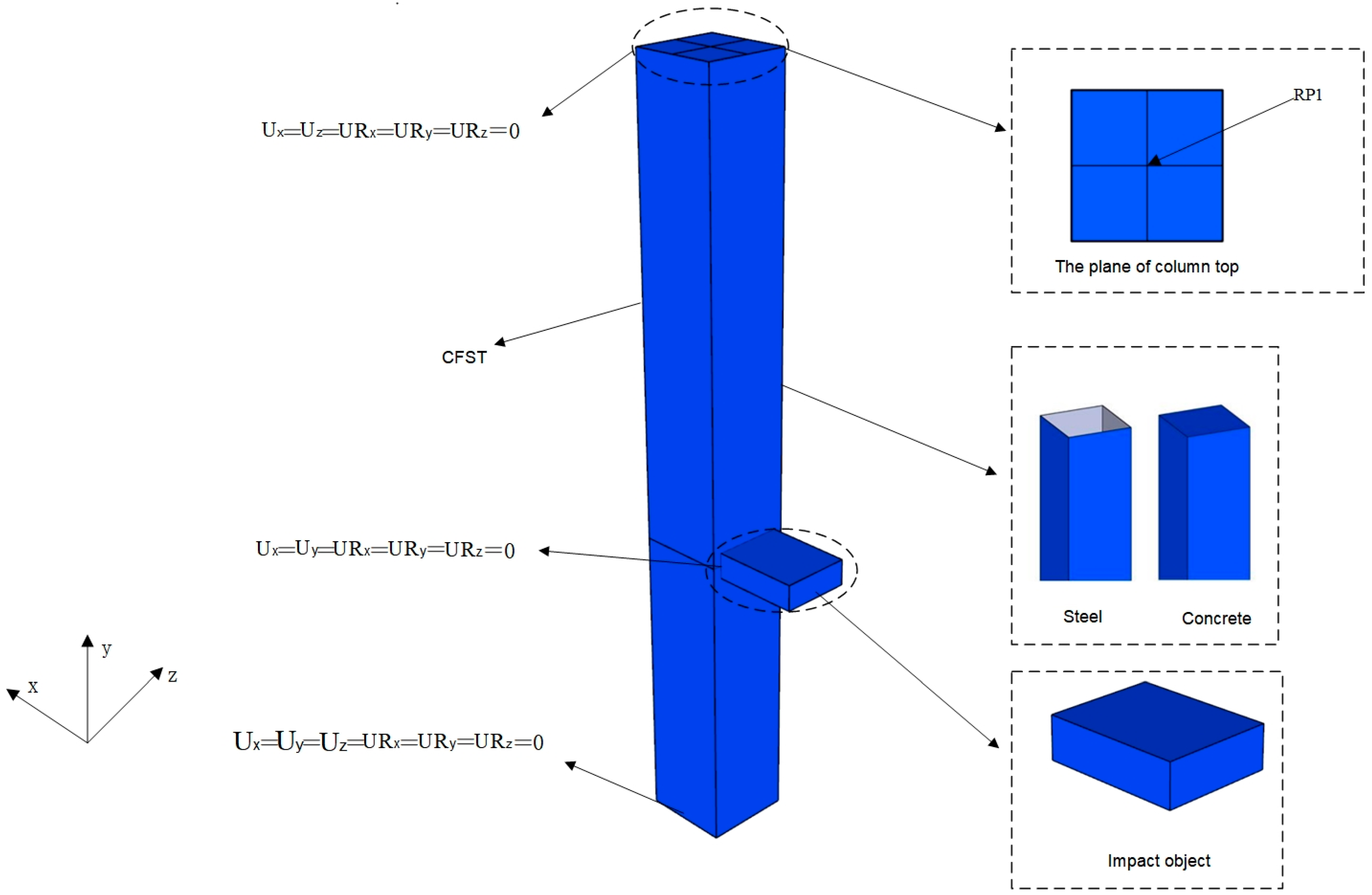
2.1. Elements

The finite element model (FEM) consisting of a steel tube, core concrete, and a dropping hammer is shown in Figure 1. The steel tube and core concrete are modeled by using the ‘C3D8R’ element, namely, a 3D eight-node linear reduced integral element with a mesh size of 50 mm which is determined by a trial running. The ‘R3D4′ element, namely, a 3D four-node bilinear quadrilateral element, is used to simulate a dropping hammer, since the deformation of the hammer is ignored.

2.2. Boundary Conditions and Contacts

To facilitate the application of boundary conditions, impact, and axial force, the reference points are set at the ends of the model and the dropping hammer, respectively. The reference point at one end of the model is set as a fixed constraint, namely, Ux = Uy = Uz = URx = URy = URz = 0. The reference point RP1 on the top of the column is constrained except for the y-direction translation degree of freedom, namely, Ux = Uz = URx = URy = URz = 0. In addition, the position of the reference point RP1 changes as the eccentricity of the member. Regardless of the free-falling process, the dropping hammer is placed in the initial position of contact with the specimen, whilst the mass and impact velocity of the dropping hammer are applied to the reference point at the dropping hammer. The impact velocity of the dropping hammer is taken from the corresponding free-fall velocity from the impact height calculated by V = 2 g h , where h is the impact height by ignoring the energy loss during the falling process of the hammer.
The interface contact of the finite element model is defined as “general contact”. For the steel tube and dropping hammer, the tangential direction of contact is defined as “frictionless”. The cohesive force between the steel tube and the concrete is calculated by Equation (1) from Ref. [15] as:
τ b o n d = 0.75 [ 2.314 0.0195 ( B / t s ) ]
where τbond is the bond stress of the contact surface, B is the concrete side length in the square concrete-filled steel tube, and ts is the thickness of the steel tube. If the shear stress of the contact surface is less than τbond, there is no relative slip at the interface. At this time, the Coulomb friction model is used to characterize the relative slip between the two and the corresponding friction coefficient is 0.6 [16].

2.3. Constitutive Relationship of Material
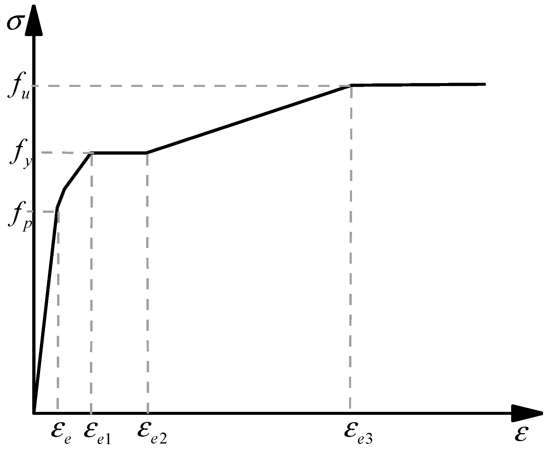
2.3.1. Steel

Based on the previous studies from the authors’ research group [12], the static material model of steel shows little effect on the performance of CFST columns under lateral impact load. Since normal-strength low-carbon steel is used in this study, the secondary plastic flow model by Han [17] is used as shown in Figure 2. The specific expression is described by Equation (2), where fp, fv, and fu represent the proportional limit, yield strength, and tensile strength of the steel, respectively.
σ s = { E s ε s ε s ε e A ε s 2 + B ε s + C ε e < ε s ε e 1 f y ε e 1 < ε s ε e 2 f y ( 1 + 0.6 ε s ε e 2 ε e 3 ε e 2 ) ε e 2 < ε s ε e 3 1.6 f y ε s > ε e 3
where εe = 0.8fy/Es, εe1 = 1.5εe, εe2 = 10εe1, εe3 = 100εe1, A = 0.2fy/(εe1 − εe)2, B = 2e1, and C = 0.8fy + Aεe2e.
The Cowper–Symonds model is used in the simulation due to its suitability for the calculation of dynamic problems with low strain rates. The model is expressed by Equation (3), where ε ˙ is the strain rate of steel, σd is the stress at the strain rate ε ˙ of steel, σs is the stress value of steel under static force, and D and P are the material fitting parameters and could be taken as 4945 s−1 and 2.696, respectively [18,19,20].
σ d / σ s = 1 + ( ε ˙ / D ) 1 / p

2.3.2. Concrete

The Concrete Damaged Plasticity (CDP) model from ABAQUS library is used to describe the mechanical behavior of concrete. The dilation angle, flow potential eccentricity, the ratio of the compressive strength under biaxial loading to the uniaxial compressive strength, fbo/fco, the ratio of the second stress invariant on the tensile meridian to that on the compressive meridian, K, and the viscosity coefficient of concrete are set to 30°, 0.1, 1.16, 0.667, and 0.0005, respectively [21].
The stress–strain relationship of concrete under uniaxial compression provided in Ref. [17] is adopted, as expressed by Equation (4):
y = { 2 x x 2 x 1 x β 0 ( x 1 ) η + x x > 1
where x = ε/ε0, y = σ/σ0, σ0 = fc, ε0 = εc + 800·ξ0.2·10−6, εc = (1300 + 12.5fc′)10−6, η = 1.6 + 1.5 / x , β 0 = ( f c ) 0.1 1.2 1 + ξ .
The uniaxial tensile stress–strain relationship of concrete is expressed by Equation (5):
y = { 1.2 x 0.2 x 6 x 1 0.31 σ p 2 ( x 1 ) 1.7 + x x > 1
where x = εcp, y = σcp, σp = 0.26 × (1.25fc)2/3, σp is the peak tensile stress of concrete, and εp = 43.1 με is the strain value corresponding to the peak tensile stress of concrete.
The effect of the strain rate of concrete is considered by using the relationship between DIF (dynamic increase factor) and strain rate ε ˙ = 3 × 10 5 300 s 1 of concrete provided by CEB-FIP (1988) [22].
(1)
Equation (6) is used for the concrete under dynamic compression:
D I F = f c d f c s = { ( ε ˙ ε ˙ s ) 1.026 α s ε ˙ 30 s 1 γ s ( ε ˙ ε ˙ s ) 1 / 3 ε ˙ > 30 s 1
where fcs and fcd are the static compression strength and dynamic compression strength respectively, γ s = 10 ( 6.156 α s 2.0 ) , α s = ( 5 + 9 f c s / f c o ) 1 , ε ˙ s = 30 × 10 6 s 1 (quasi-static strain rate), and fco = 10 MPa.
(2)
Equation (7) is used for the concrete under dynamic tension:
D I F = f t d f t s = { ( ε ˙ ε ˙ s ) 1.016 δ ε ˙ 30 s 1 β ( ε ˙ ε ˙ s ) 1 / 3 ε ˙ > 30 s 1
where δ = (10+fcs/fco)−1, β = 107.11δ−2.33, fts, and ftd are the static tensile strength and dynamic tensile strength, respectively, ε ˙ s = 30 × 10 6 s 1 (quasi-static strain rate), and fco = 10 MPa.

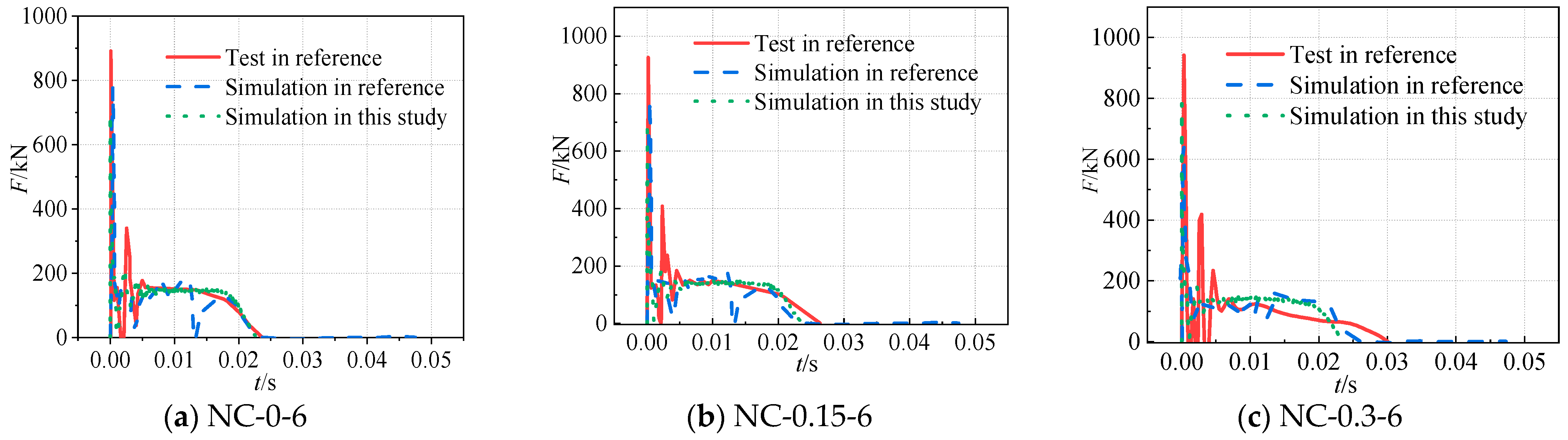
2.4. Model Validation

The results of the axial force–impact coupling tests from Ref. [23] are used to validate the finite element model. The steel tube used in the tests was cut from a pre-fabricated cold-formed square hollow section with an average thickness of 2.45 mm. The average yield strength, tensile strength, elastic modulus, and Poisson’s ratio of steel are 370.8 MPa, 446.5 MPa, 1.98 × 10⁵ N/mm2, and 0.267, respectively. The compressive strength and elastic modulus of concrete are 53.9 MPa and 3.29 × 10⁴ MPa, respectively. The relevant test information is listed in Table 1 and more detailed information can be found in Ref. [23].
As shown in Figure 3, the impact force–time history curves of the three specimens in Table 1 mainly experienced three stages: oscillation stage, stable stage, and attenuation stage. From the impact force–time history curves for different axial compression ratios, it can be concluded that the impact force platform value gradually decreases as the axial force increases. This is due to the increased ability of the column to resist lateral impact under axial force within a certain range, resulting in a decrease in the deflection and the impact force platform value. In general, the overall trends of the curves and the magnitudes of the feature values are similar, indicating that the finite element models can accurately reflect the effect of axial force on the impact performance of CFST columns.

3. Effect of the Axial Compression Ratio on Impact Performance of the CFST Columns

Axial compression ratio is an important parameter affecting the lateral impact resistance of CFST columns [24,25]. In this section, the axial compression ratio n is taken as 0, 0.1, 0.2, 0.3, 0.4, and 0.5 whilst the steel tube is Q345, the concrete is C60, and the eccentricity is zero. According to the previous studies from the authors’ research group [12], the cross-sectional shape for the same cross-sectional area and the shape of the drop hammer are also expected to have little effect on the lateral impact performance of CFST columns. Therefore, the size of the dropping hammer is set as 120 mm × 320 mm × 400 mm and only a square section tube is used in the model. Besides, aiming to provide a reference for practical design and application, only a full-scale height of square CFST is used in this study. The detailed parameters of the specimens are given in Table 2.
The platform value of the impact force of the models is calculated by using Equation (8) from Ref. [10]:
F p = t 0 t 2 F ( t ) d t t 2 t 0
where F(t) is the impact force, t0 is the moment when the impact force reaches the peak value, and t2 is the moment when the deflection reaches the peak value.

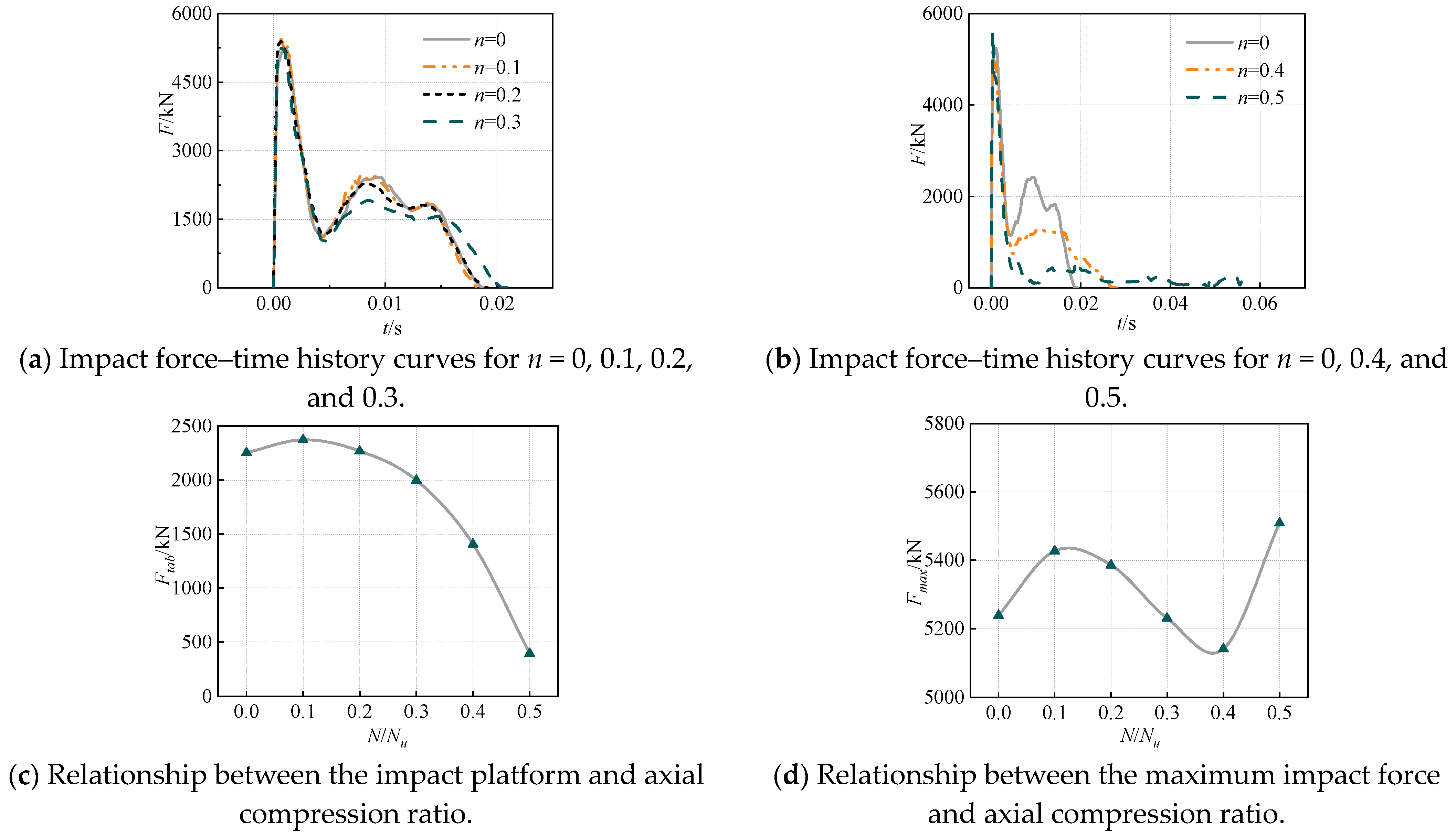
3.1. Impact Force Curve

From Figure 4a,b, it can be seen that as the axial compression ratio increases, the duration of impact force gradually increases. As shown in Figure 4c, the impact platform value with an axial compression ratio of 0.1 is greater than that without axial compression. For an axial compression ratio of 0.2, the impact platform value is almost the same as that without axial compression. With the increase in the axial compression ratio, the impact platform values of the specimens under axial forces are generally lower than those without axial forces. As shown in Figure 4d, the peak impact force of the CFST column is less affected by the axial force, since the time consumed at the beginning of the impact is very short and the axial compression hardly affects the peak impact force between the impact body and the column. When n > 0.2, the increase in the axial force accelerates the bending of the CFST column. In other words, increasing the axial force leads to more obvious second-order effects and decreases the impact resistance of CFST columns.

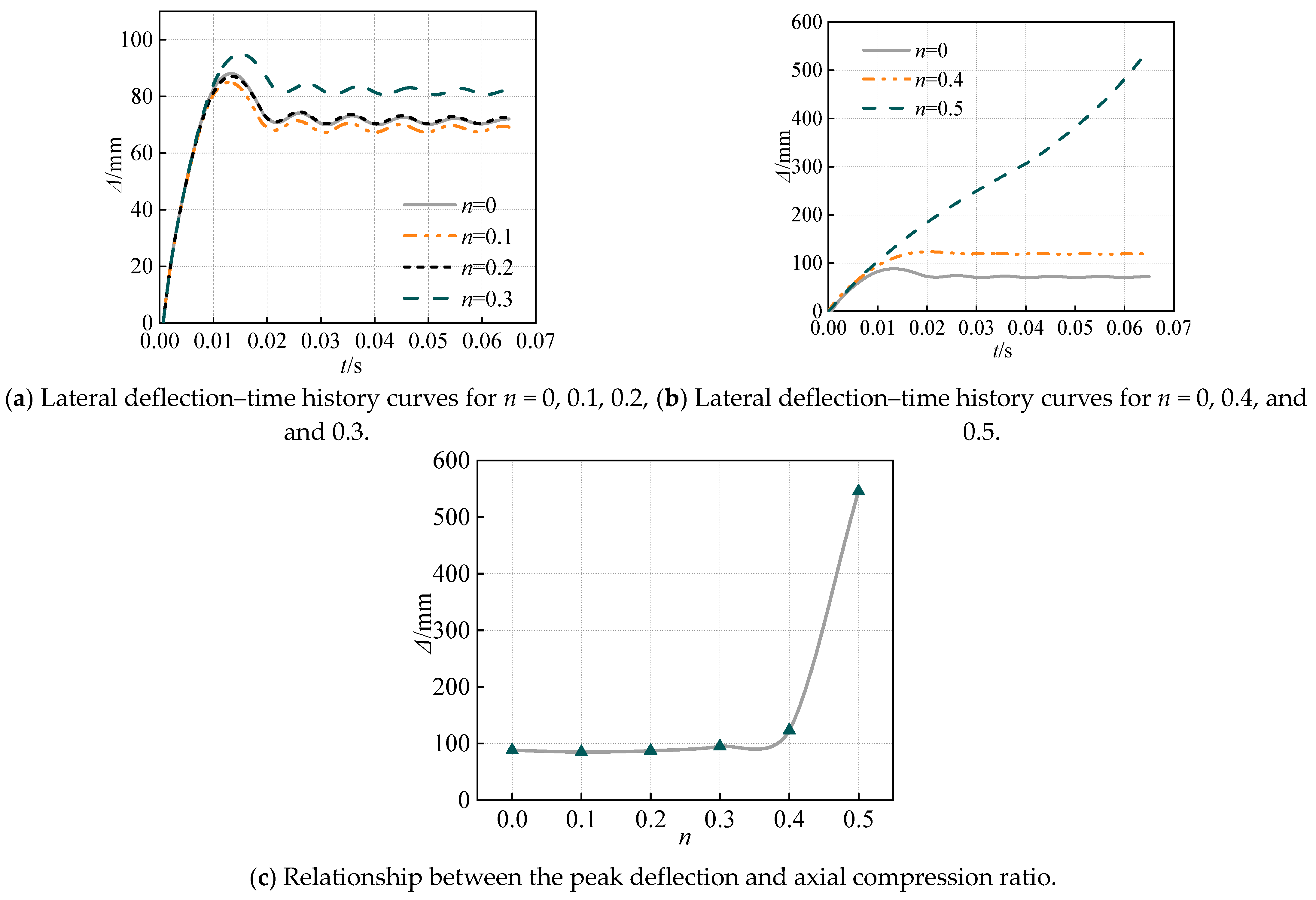
3.2. Deflection Curves

It can be seen from Figure 5a,b that when the axial compression ratio is relatively low, the lateral deflection curves of the CFST column show oscillations after reaching the peak values. As the axial compression ratio increases, the oscillation amplitudes weaken or even disappear. The deflection of the member with the axial compression ratio of 0.1 is lower than that without axial force, decreasing from 87.95 mm to 84.93 mm, indicating that the axial force enhances the sectional resistance of the member. For an axial compression ratio of 0.2, the peak values of the deflection curves are almost the same as those without axial force. At the axial compression ratio of 0.5, the lateral deflection is 545.46 mm, and the column is damaged. Since the axial force accelerates the bending of the member, the deflection of the member increases rapidly under the lateral impact, as shown in Figure 5c.

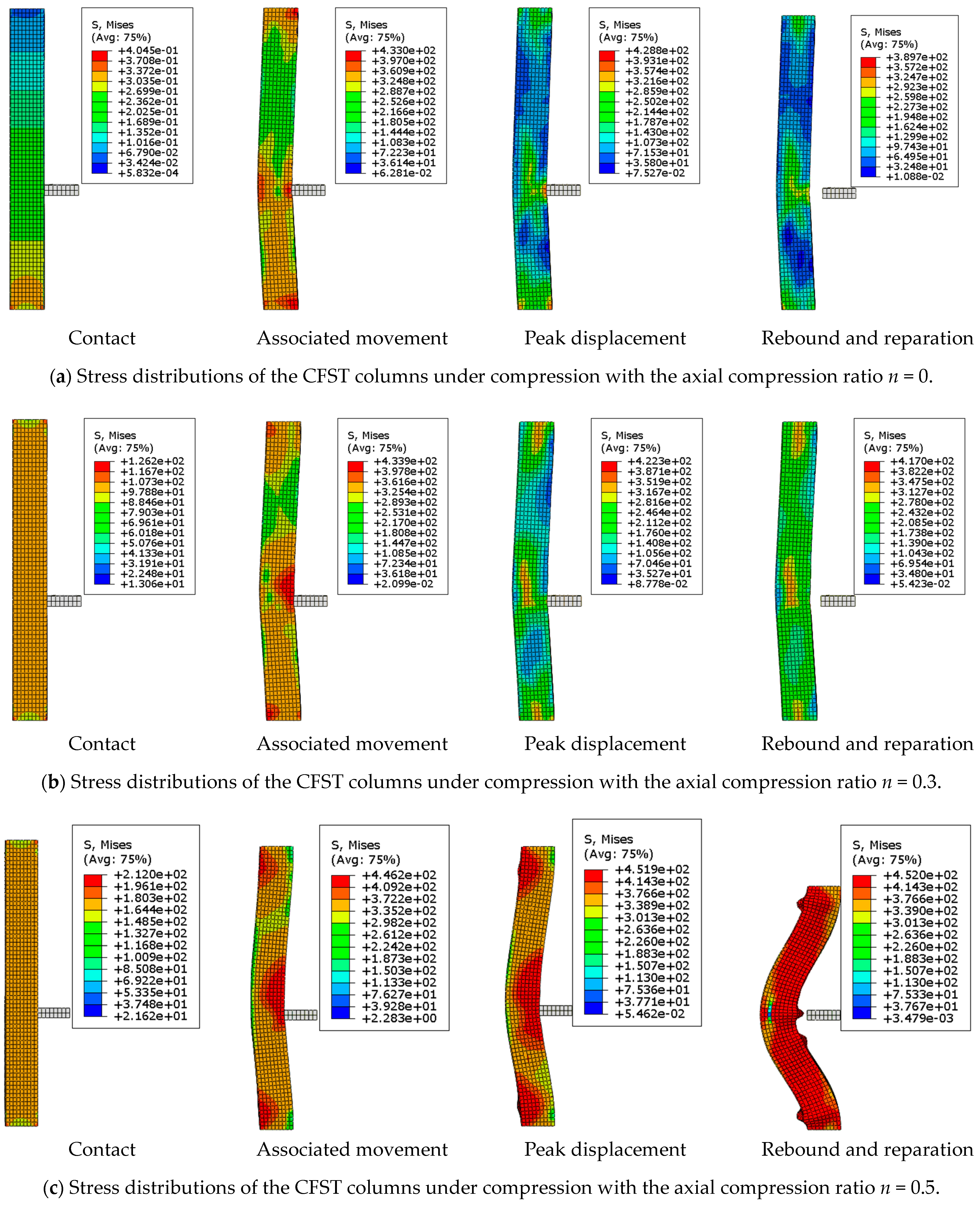
3.3. Stress Contours

As shown in Figure 6a, it can be seen that the stress of the CFST column without axial force is almost zero before the lateral impact begins. With the increase in the axial compression ratio, the stress of the entire column increases, as shown in Figure 6b,c. Under the action of lateral impact, the impact part and both ends of the column are higher stress areas. With the increase in the axial compression ratio, the range of the high-stress area expands. As for the continuous effect of the impact, the high-stress regions at the impact site and the two ends of the column expand successively, and the overall bending deformation range of the CFST column also increases. During the rebound and reparation stage, the impacted part and the backs of the two ends of the column appear to buckle, and typical overall bending damage occurs in the column.

4. Parametric Studies on the Dynamic Compression-Bending Performances of the CFST Columns

4.1. Model Introduction

To investigate the dynamic compression-bending performances of the eccentric compression CFST columns under lateral impact, the eccentricity, concrete strength, steel strength, and steel ratio of CFST columns are considered. The section of the steel tube is B × B = 400 mm × 400 mm whilst the tube thicknesses are 5 mm, 10 mm, and 15 mm, respectively. The overall height H of the column is 3500 mm. The steel tube is made of Q235, Q345, and Q390 steel, and the core concrete is made of C40, C50, and C60 concrete grades. The eccentricities are set as 0 mm, 35 mm, 45 mm, and 55 mm, respectively. The basic parameters of the specimens are given in Table 3. The simulated results are summarized in Table 4. The formula for calculating the axial compression resistances of square CFST columns is Equation (9):
N ( 1 / γ ) N u
N u = f A s + f c A c
where f is the compressive strength of the steel tube, fc is the axial compressive strength of the core concrete, As is the cross-sectional area of the steel tube, Ac is the cross-sectional area of the core concrete, N is the design value of the axial resistance, Nu is the sectional compressive-bearing capacity, and γ is the coefficient according to Technical Regulations for Rectangular Concrete-Filled Steel Structures.
The bending capacity of the models is calculated according to Equation (11) [26], where the bending moment is extracted from the impact position section of the models:
M u = γ m W s c f s c
where fsc is the compressive strength of the concrete-filled steel tube, γm is the coefficient of plastic development, and Wsc is the section modulus of the bending member.

4.2. Analysis of the Results
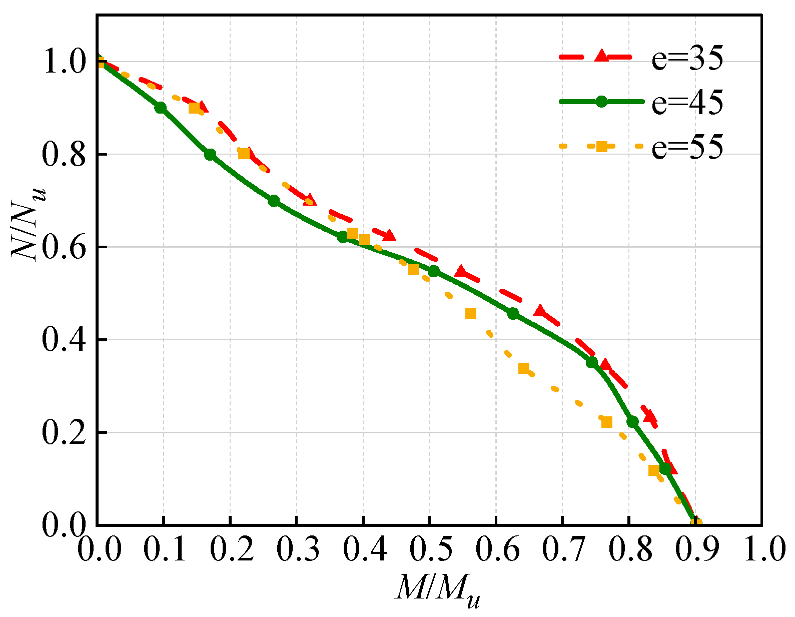
4.2.1. Eccentricity

To investigate the influence of eccentricity on the dynamic compression-bending performances of eccentric compression CFST columns under lateral impact, the eccentricity values of e = 35 mm, 45 mm, and 55 mm are adopted. It can be seen from Figure 7 that the dynamic N/NuM/Mu curves for different eccentricities show decreasing trends. The curves are divided into two parts at N/Nu = 0.6. Even as the normalized curves, the increase in the eccentricity would decrease the enveloping areas of the dynamic N/NuM/Mu curves of the CFST columns, indicating the worse impact resistances.

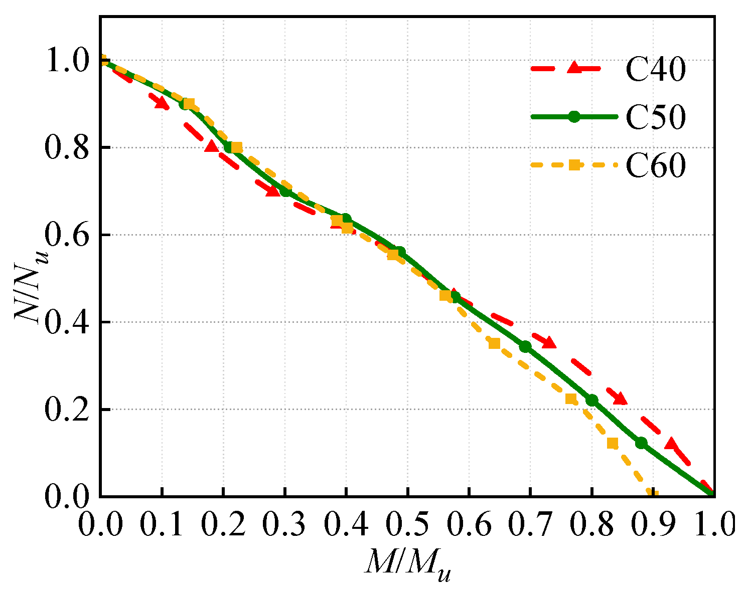
4.2.2. Concrete Strength

To investigate the influence of concrete strength on the dynamic compression-bending performances of eccentric compression CFST columns under lateral impact, C40, C50, and C60 concrete grades are adopted. It can be seen from Figure 8 that the dynamic N/Nu–M/Mu curves with different concrete strengths show decreasing trends. At M/Mu = 0.55, the three curves almost intersect at one point. The N/Nu–M/Mu curves for the eccentric compression CFST columns indicate that the increase in the concrete strength has a minor effect on the bending capacity of the columns. This is because the core concrete in the concrete-filled steel tube contributes little to the flexural strength of the member sections and plays a supporting role under lateral impact.

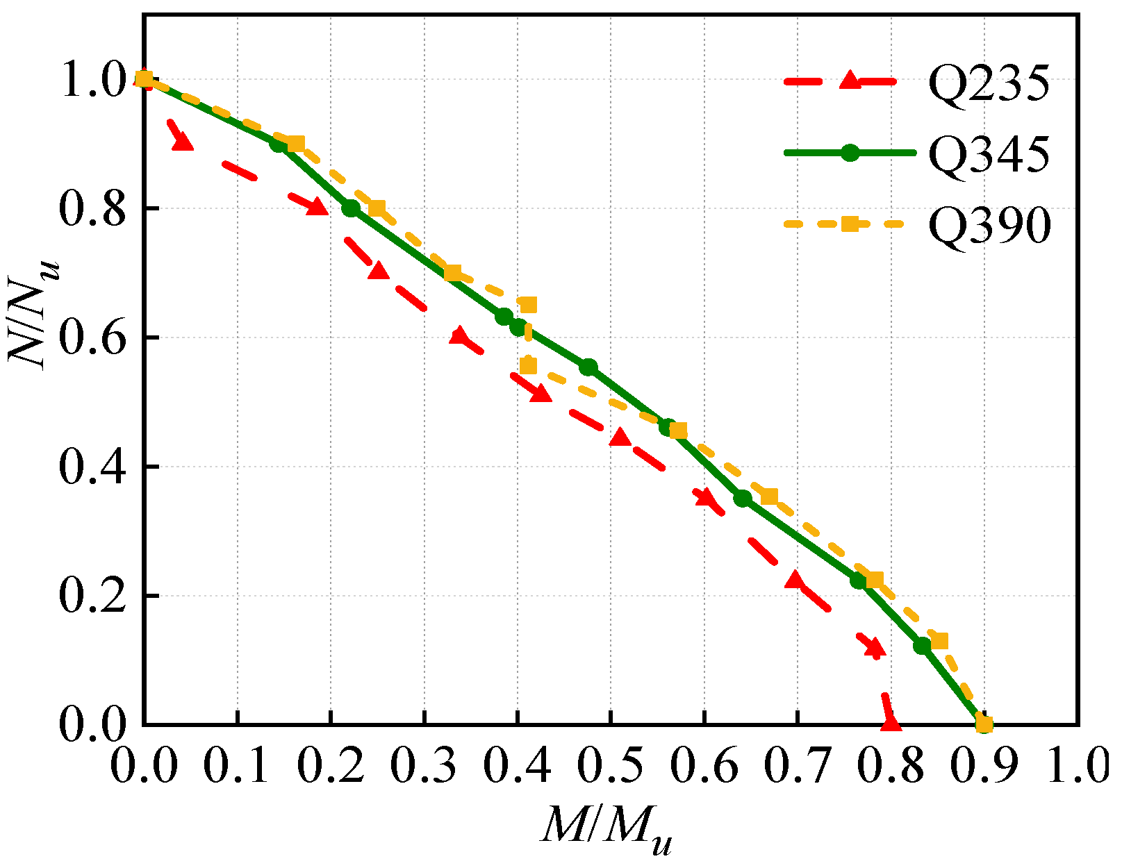
4.2.3. Steel Strength
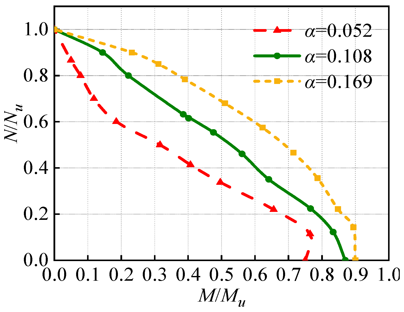
To investigate the influence of steel strength on the dynamic compression-bending performances of eccentric compression CFST columns under lateral impact, Q235, Q345, and Q390 steel grades are selected. As can be seen from Figure 9, the dynamic N/NuM/Mu curves with different steel strengths show decreasing trends. At the beginning of the curve, the CFST column with Q235 steel has the smallest M/Mu value. With the increasing steel strength, the restraint effect on the core concrete is enhanced and thus it has a better ability to delay deformation.

4.2.4. Steel Ratio

To investigate the influence of steel ratio on the dynamic compression-bending performances of eccentric compression CFST columns under the lateral impact, the steel ratios of α = 0.052, 0.108, and 0.169 are adopted. It can be seen from Figure 10 that the M/Mu values increase significantly with the increasing steel ratio, indicating better dynamic compression-bending performances of the model. This is because increasing the steel ratio improves the resistance and stiffness of the columns which can largely delay the deformation.

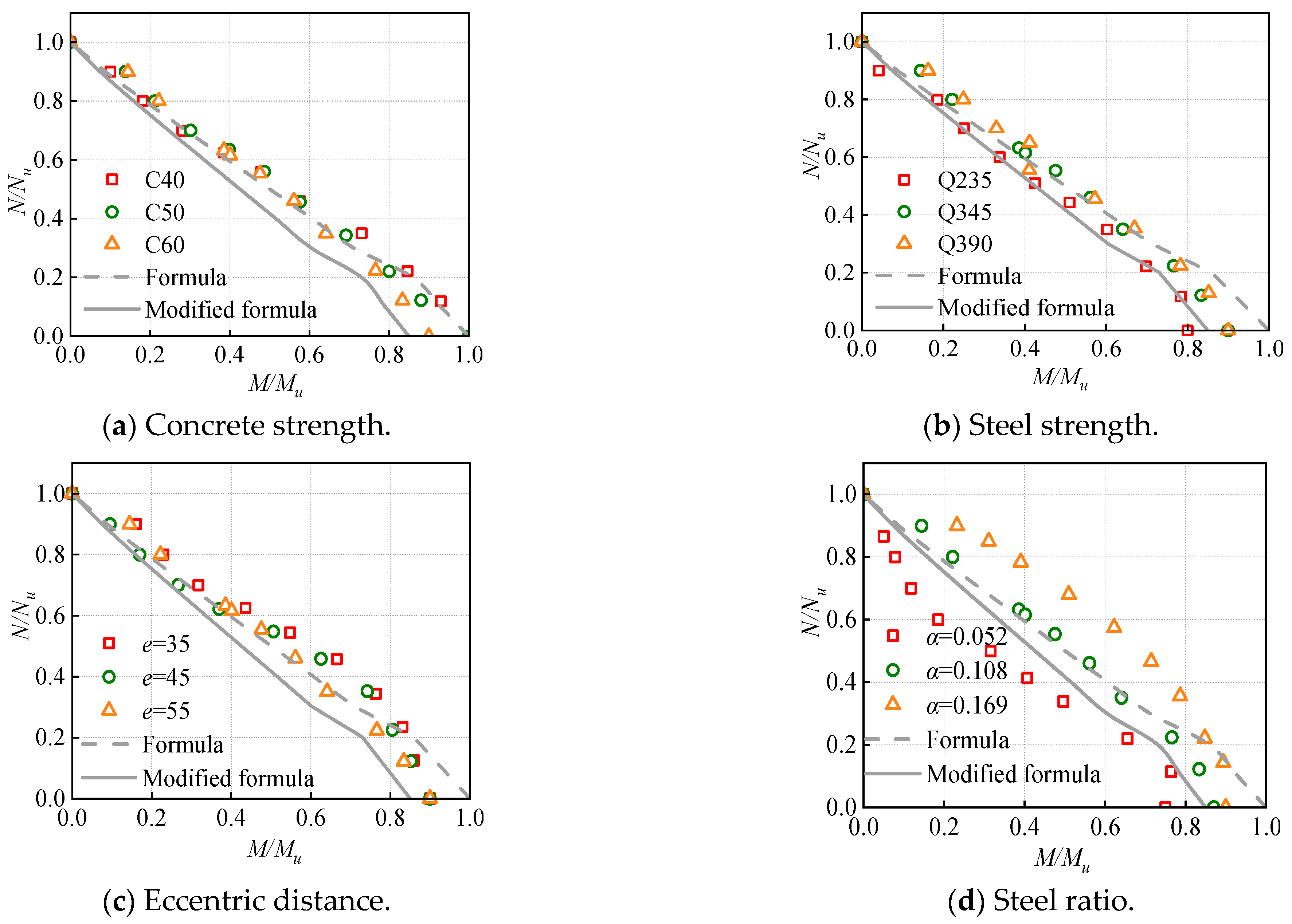
5. Dynamic Compression-Bending Formula for the CFST Columns

According to the above parameter analysis, the dynamic compression-bending formula for the eccentric compression CFST columns can be divided into two parts:
When (N/Nu) ≤ 0.2,
a ( N N u ) + ( M M u ) = b
Through the analysis of the previous results, the fitting coefficients a and b are 0.7 and 1.0, respectively, so the compression-bending formula of CFST columns can be expressed as Equation (13):
0.7 ( N N u ) + ( M M u ) = 1
When (N/Nu) > 0.2,
( N N u ) a + ( M M u ) b = 1
Through the analysis of the previous results, the fitting coefficients a and b are 1.1 and 1.1, respectively, so the compression-bending formula for CFST columns can be expressed as Equation (15):
( N N u ) 1.1 + ( M M u ) 1.1 = 1
where N and M are the axial force and bending moment of concrete-filled steel tube columns, respectively, Nu is the axial compressive resistance of CFST columns, and Mu is the flexural resistance of CFST columns.
From Figure 11, it can be seen that the fitting accuracy of the formula is high with R2 = 0.95. To have sufficient strength reserves for the practical design, the fitting formula is modified as Equations (16) and (17). The predicted results from the modified formula are all smaller than the simulated results, indicating the dynamic N-M strength reserves by using Equations (16) and (17). The differences between the simulated and the predicted results from the modified formulas are approximately 20%.
When (N/Nu) ≤ 0.2,
0.7 ( N N u ) + 20 17 ( M M u ) = 1
When (N/Nu) > 0.2,
( N N u ) 1.1 + 20 17 ( M M u ) 1.1 = 1
The proposed dynamic compression-bending formula for CFST columns could be used to determine the corresponding internal forces of CFST columns when considering the impact design. Then the section design of CFST columns under the design service loads and impact load could be conducted by using the most unfavorable internal load combination.

6. Conclusions

In this paper, the dynamic compression-bending performances of CFST columns under lateral impact load are studied. Some conclusions are drawn as follows.
(1)
The axial compression ratio of 0.2 is a feature point to evaluate the impact resistance of the CFST column. The axial force ratio shows a positive effect on the impact resistance of CFST columns when less than 0.2, otherwise the axial force would degrade the impact resistance of CFST columns.
(2)
The increase in the steel strength and steel ratio rather than the concrete strength has a positive effect on the dynamic compression-bending performances of eccentric compression CFST columns under impact.
(3)
Based on the simulated results with different parameters, a high-accuracy dynamic compression-bending formula for CFST columns is obtained. The formula is also modified to have a sufficient strength reserve for the practical design.

Author Contributions

Methodology, M.X.; Formal analysis, X.H.; Writing—original draft, Z.D.; Writing—review & editing, S.G. All authors have read and agreed to the published version of the manuscript.

Funding

The project is supported by the National Natural Science Foundation of China (Grant No. 51908085), Fundamental Research Funds for the Central Universities (Grant No. AUGA5710010322), and The Youth Innovation Team of Shaanxi Universities (Grant No. 21JP138).

Data Availability Statement

The raw/processed data required to reproduce these findings can be shared.

Acknowledgments

The project is supported by the National Natural Science Foundation of China (Grant No. 51908085), Fundamental Research Funds for the Central Universities (Grant No. AUGA5710010322), and The Youth Innovation Team of Shaanxi Universities (Grant No. 21JP138), which are gratefully acknowledged.

Conflicts of Interest

We declare that we do not have any commercial or associative interest that represents any conflict of interest in connection with the work submitted.

References

  1. Han, L.H. Theory and Practice of Concrete-Filled Steel Tubular Structures; Science Press: Beijing, China, 2017; pp. 66–110. [Google Scholar]
  2. Zhang, C. Dynamic Analysis of Concrete-Filled Steel Tubular Columns under Impact Load; Taiyuan University of Technology: Taiyuan, China, 2005. [Google Scholar]
  3. Li, Z.; Li, B.; Li, Y.G.; Ren, G.P. Discussion on dynamic characteristics of axial impact of concrete-filled steel tubular short columns. J. Taiyuan Univ. Technol. 2006, 4, 383–385. [Google Scholar]
  4. Zheng, Q. Experimental Study and Finite Element Analysis on Impact Resistance of Concrete-Filled Steel Tubular Short Columns; Hunan University: Changsha, China, 2008. [Google Scholar]
  5. Mirmomeni, M.; Heidarpour, A.; Zhao, X.L.; Al-Mahaidi, R. Size-dependency of concrete-filled steel tubes subject to impact loading. Int. J. Impact Eng. 2017, 100, 90–101. [Google Scholar] [CrossRef]
  6. Qu, H.; Li, G.; Chen, S.; Sun, J.; Sozen, M.A. Analysis of circular concrete-filled steel tube specimen under lateral impact. Adv. Struct. Eng. 2011, 14, 941–951. [Google Scholar] [CrossRef]
  7. Liu, Y.L. Experimental Study and Numerical Analysis of Lateral Impact Response of Concrete-Filled Steel Tubular Members with Common Constraint Types; Taiyuan University of Technology: Taiyuan, China, 2005. [Google Scholar]
  8. Han, L.H.; Hou, C.C.; Zhao, X.L.; Rasmussen, K.J.R. Behavior of high-strength concrete-filled steel tubes under transverse impact loading. J. Constr. Steel Res. 2014, 92, 25–39. [Google Scholar] [CrossRef]
  9. Hou, C.C.; Han, L.H. Life-cycle performance of deteriorated concrete-filled steel tubular (CFST) structures subject to lateral impact. Thin-Walled Struct. 2018, 132, 362–374. [Google Scholar] [CrossRef]
  10. Yang, X.Q. Dynamic Constitutive Model of Structural Steel and Lateral Impact Resistance of High Strength CFST Square Members; Harbin Institute of Technology: Harbin, China, 2020. [Google Scholar]
  11. Wang, L.M.; Liu, Y.H.; Zhao, S.C.; Zhao, Y.C.; Kang, X.J. Research on cracking evaluation model and influencing factors of concrete-filled steel tubular members under lateral low-velocity impact. J. Civ. Eng. 2022, 55, 7–17. [Google Scholar]
  12. Gao, S.; Xu, Y.C.; Zhang, S.M.; Derlatka, A. Performance of square concrete-filled steel tubular columns under repeated lateral impact. Eng. Struct. 2023, 280, 115719. [Google Scholar] [CrossRef]
  13. Ostrowski, K.; Dudek, M.; Sadowski, L. Compressive behaviour of concrete-filled carbon fiber-reinforced polymer steel composite tube columns made of high performance concrete. Compos. Struct. 2020, 234, 111668. [Google Scholar] [CrossRef]
  14. Ostrowski, K.; Chastre, C.; Furtak, K.; Malazdrewicz, S. Consideration of critical parameters for improving the efficiency of concrete structures reinforced with FRP. Materials 2022, 15, 2774. [Google Scholar] [CrossRef] [PubMed]
  15. Symonds, P.S. Survey of methods of analysis for plastic deformation of structures under dynamic Loading. Ciência Technol. Aliment. 1967, 31, 967–972. [Google Scholar]
  16. Han, L.; Yao, G.; Tao, Z. Performance of concrete-filled thin-walled steel tubes under pure torsion. Thin-Walled Struct. 2007, 45, 24–36. [Google Scholar] [CrossRef]
  17. Han, L.H. Concrete-Filled Steel Tubular Structure: Theory and Practice; Science Press: Beijing, China, 2007. [Google Scholar]
  18. Forni, D.; Chiaia, B.; Cadoni, E. Strain rate behaviour in tension of S355 steel: Base for progressive collapse analysis. Eng. Struct. 2016, 119, 164–173. [Google Scholar] [CrossRef]
  19. Reid, S.R.; Reddy, T.Y. Static and dynamic crushing of tapered sheet metal tubes of rectangular cross-section. Int. J. Mech. Sci. 1986, 28, 623–637. [Google Scholar] [CrossRef]
  20. Abramowicz, W.; Jones, N. Dynamic progressive buckling of circular and square tubes. Int. J. Impact Eng. 1986, 4, 243–270. [Google Scholar] [CrossRef]
  21. Tao, Z.; Wang, Z.; Yu, Q. Finite element modelling of concrete-filled steel stub columns under axial compression. J. Constr. Steel Res. 2013, 133, 121–131. [Google Scholar] [CrossRef]
  22. CEB-FIP. Concrete Structures under Impact and Impulsive Loading—Synthesis Report; Comite Euro-International du Beton: Lausanne, Switzerland, 1988; Volume 187, 184p. [Google Scholar]
  23. Yang, Y.F.; Zhang, Z.C.; Fu, F. Experimental and numerical study on square RACFST members under lateral impact loading. J. Constr. Steel Res. 2015, 111, 43–56. [Google Scholar] [CrossRef]
  24. Jia, D.B. Preliminary Study on Concrete-Filled Steel Tubular Members under Lateral Impact Load; Taiyuan University of Technology: Taiyuan, China, 2005. [Google Scholar]
  25. Gao, S.; Zhao, G.H.; Guo, L.H.; Zhou, L.Q.; Yuan, K.K. Utilization of coal gangue as coarse aggregates in structural concrete. Constr. Build. Mater. 2021, 268, 121212. [Google Scholar] [CrossRef]
  26. Cai, S.H. Contemporary Concrete-Filled Steel Tube Structure; Beijing People’s Traffic Press: Beijing, China, 2003. [Google Scholar]
Figure 1. Finite element model.
Buildings 13 02289 g001
Figure 2. Stress–strain relationship curve for steel.
Buildings 13 02289 g002
Figure 3. Comparisons of the simulated and tested results.
Buildings 13 02289 g003
Figure 4. Impact force-related curves.
Buildings 13 02289 g004
Figure 5. Deflection-related curves.
Buildings 13 02289 g005
Figure 6. Comparison of the stress distributions of the CFST columns under different axial compression ratios.
Buildings 13 02289 g006
Figure 7. Effect of eccentricity on the dynamic N/Nu–M/Mu curves.
Buildings 13 02289 g007
Figure 8. Effect of concrete strength on the dynamic N/NuM/Mu curves.
Buildings 13 02289 g008
Figure 9. Effect of steel strength on the dynamic N/Nu–M/Mu curves.
Buildings 13 02289 g009
Figure 10. Effect of steel ratio on the dynamic N/NuM/Mu curves.
Buildings 13 02289 g010
Figure 11. Comparisons of the simulated and predicted results.
Buildings 13 02289 g011
Table 1. Details of the test specimens in Ref. [23].
GroupSpecimen NumberAxial Compression RatioLength/mmCross Section/mmHammer Weight/kgImpact Velocity/(m/s)
1NC-0-601800B × t = 100 × 2.4523810.85
2NC-0.15-60.151800B × t = 100 × 2.4523810.85
3NC-0.3-60.31800B × t = 100 × 2.4523810.85
Table 2. Parameters and results of the axial compression specimens.
Axial Compression Ratio nB × t/mmSpecimen Height H/mImpact Mass m/tImpact Speed V /m/sImpact Height H/mFmax/kNFstab/kNΔ/mm
0400 × 103.51.85616.671.3855238.782252.9187.95
0.15427.202371.8384.93
0.25386.242268.7987.07
0.35230.591997.7994.93
0.45140.481405.63123.35
0.55509.12393.03545.46
Note: Fmax is the maximum value of the impact force, Fstab is the platform value of the impact force, and Δ is the peak deflection of the concrete-filled steel tubular column.
Table 3. Detailed information of the specimens.
Specimen NumberColumn Section Size/mmConcreteSteelEccentric Distance/mmSteel Ratio/α
CF1400 × 400 × 10C60Q34500.108
CF2400 × 400 × 10C50Q345550.108
CF3400 × 400 × 10C40Q345550.108
CF4400 × 400 × 10C60Q235550.108
CF5400 × 400 × 10C60Q345550.108
CF6400 × 400 × 10C60Q390550.108
CF7400 × 400 × 10C60Q345350.108
CF8400 × 400 × 10C60Q345450.108
CF9400 × 400 × 5C60Q345550.052
CF10400 × 400 × 15C60Q345550.169
Table 4. Calculations of the bending moment M of the eccentric compression CFST columns under impact.
Numbern = 0n = 0.1n = 0.2n = 0.3n = 0.4n = 0.5n = 0.6n = 0.7n = 0.8n = 0.9
CF2942.7909.3828.0714.7562.9467.9377.8274.6177.098.0
CF3956.0920.2836.3722.8602.6508.6416.4315.6220.6143.9
CF4961.2924.7849.5711.1622.6527.7427.6445.3245.8160.1
CF5704.3678.9604.8522.2442.2368.6293.3217.8160.936.1
CF61059.6102694.3806.3689.4495.3495.9397.8300.0196.2
CF7952.4953.4921.5847.0738.2607.6483.5351.8254.1177.8
CF8951.2944.9893.1823.0693.8561.5409.9295.8188.7105.4
CF9540.2550.4472.2357.3293.0227.5133.485.256.545.4
CF101297.31282.012161128.21025.1892.8731.4560.0446.2332.8
Disclaimer/Publisher’s Note: The statements, opinions and data contained in all publications are solely those of the individual author(s) and contributor(s) and not of MDPI and/or the editor(s). MDPI and/or the editor(s) disclaim responsibility for any injury to people or property resulting from any ideas, methods, instructions or products referred to in the content.

