Article

Integrating BIM–IoT and Autonomous Mobile Robots for Construction Site Layout Printing

1
Department of Civil Engineering, Ghulam Ishaq Khan Institute of Engineering Sciences & Technology, Topi 23640, Pakistan
2
School of Surveying and Built Environment, University of Southern Queensland, Springfield Central, QLD 4300, Australia
*
Author to whom correspondence should be addressed.
Buildings 2023, 13(9), 2212; https://doi.org/10.3390/buildings13092212
Submission received: 1 August 2023 / Revised: 28 August 2023 / Accepted: 29 August 2023 / Published: 30 August 2023

Abstract

:
The traditional methods of marking construction site layouts using manual techniques such as chalk lines are prone to human errors, resulting in discrepancies between blueprints and actual layouts. This has serious implications for project delivery, construction, costs and, eventually, project success. However, this issue can be resolved through autonomous robots and construction automation in line with Industry 4.0 and 5.0 goals. Construction automation enables workers to concentrate on the construction phase and not worry about manual site markups. This leads to an enhancement in their productivity. This study aims to improve the floor layout printing technique by introducing a framework that integrates building information modeling (BIM) and the Internet of Things (IoT), i.e., BIM–IoT and autonomous mobile robots (AMR). The development process focuses on three key components: a marking tool, an IoT-based AMR and BIM. The BIM-based tools extract and store coordinates on the cloud platform. The AMR, developed using ESP32 and connected to the Google Firestore cloud platform, leverages IoT technology to retrieve the data and draw site layout lines accordingly. Further, this research presents a prototype of an automated robot capable of accurately printing construction site layouts. A design science research (DSR) method is employed in this study that includes a comprehensive review of the existing literature and usage of AMRs in construction layout printing. Subsequently building upon the extant literature, an AMR is developed and experiments are conducted to evaluate the system’s performance. The experiment reveals that the system’s precision falls within a range of ±15 mm and its angle accuracy is within ±4 degrees. Integrating robotic automation, IoT and BIM technologies enhances the efficiency and precision of construction layout printing. The findings provide insights into the potential benefits of deploying AMRs in construction projects, reducing site layout errors and improving construction productivity. This study also adds to the body of knowledge around construction automation in line with Industry 4.0 and 5.0 endeavors.

1. Introduction

The construction industry has been lagging behind other sectors, such as manufacturing, for years in terms of productivity [1]. According to McKinsey Global Institute, productivity in manufacturing has nearly doubled whereas in the same period, construction has experienced stagnant growth since 2005 [2]. Nowadays, one of the biggest concerns is the lack of skilled construction workers or the general availability of construction workers and the application of innovative technologies [3]. Construction automation, particularly robotics-based automation, can reduce some of the pressure brought on by the labor shortage and help boost productivity [4,5,6]. Several sectors have benefited from the Industry 4.0 revolution to create programs that use automated technologies for handling operations [7]. However, there is still a long way to go for the construction industry in terms of digital transformation and making full use of the potential technologies [8].
In the construction industry, project inefficiencies such as poor productivity, cost overruns and the need for rework pose a significant challenge [9,10]. Remarkably, 90% of projects encounter cost overruns [11], resulting in profound financial ramifications. It is projected that the implementation of productivity enhancements has the potential to yield a remarkable annual cost savings of approximately USD 1.63 trillion to the industry [12]. Hence, it is unsurprising that enhancing project efficiency has become a top priority for construction leaders. The study found that, among the various factors contributing to costs, construction site layout plays a crucial role and can account for up to 25% of a project’s expenses [13]. One of the main reasons for this is the high labor costs resulting from a shortage of skilled workers. The lack of expertise or the ability to minimize errors leads to delays, further adding to the project costs [14]. Therefore, to meet the rising demands of the construction industry, automation of construction processes to eliminate inefficiencies has become an urgent and essential task for contractors and industry leaders alike.
Construction site layout operation uses floor-marking elements, including the position of door windows, free-access flooring and dry walls. To mark their future positions on the floor and other surfaces at the construction site, the construction workers first use measuring tapes to create marks and lines with chalk. This process often requires multiple people with a high level of skill to carry out this activity.
Thousands of lines and marks must be drawn manually while constructing large buildings and infrastructures, requiring high precision and time from workers. Depending on the expertise of the on-site personnel, such as carpenters, standard manual layout-printing procedures have varying degrees of precision [15]. Additionally, one of the primary issues for construction rework is often the differences between the on-site layout and the blueprint [16]. The traditional method is suitable for small-scale labor because it heavily depends on workers’ skills and may not be useful for mega projects [17]. The usage of manual methods leads to layout clashes, resulting in variations in mega projects. Earlier studies suggest that the total cost of rework due to construction errors in layout could range between 5% to 25% of the total rework [18].
In recent years, surveying technology has advanced remarkably. Measuring tools like the total station and laser scanner are frequently utilized on building sites. Prior research to enhance the effectiveness of the lining/marking job performed by these devices can be categorized as a support technology. Support technology is intended to improve the efficiency of the manual or automated marking process [19]. Construction workers will be more productive if they can focus on installing building components while the marking process is automated through robots [20]. These robots could be programmed to interpret data from CAD models and accurately mark reference points or lines on construction sites.
Building information modeling (BIM) is a cutting-edge technology that revolutionizes how construction projects are designed, managed and executed [21]. It represents the functional and physical aspects of an infrastructure or building, integrating various data elements such as 3D models, spatial relationships, material specifications and project schedules. This technology streamlines the construction process, improves efficiency, reduces rework and saves time and costs [22]. The ability of BIM to provide detailed and accurate information makes it an ideal tool for automating construction processes, especially when combined with robotics. By leveraging BIM data, robotic systems can be integrated into the construction processes to perform complex and repetitive tasks with higher precision and reliability [23]. This integration offers a unique response to mitigate the challenges of automation, curb the effects of labor shortages and improve productivity in the construction industry [24].
Over the last two decades, robotics in construction (RiC) has emerged as a diverse and interdisciplinary field, integrating technologies like additive manufacturing, deep learning and BIM [25]. The rapidly expanding literature covers various applications, from robotic excavators and construction drones to specialized robots like façade cleaners [26,27]. RiC promises to revolutionize the construction industry, improving efficiency, safety and sustainability. However, more research and collaboration is needed to fully exploit its potential.
Unlike industrial robots, the benefits of RiC are not yet fully utilized in the construction sector due to its slow adoption and lagging behind the technology adoption curve [28,29]. One of the challenges in developing and implementing RiC is the need for expert knowledge from both robotics and construction. The situation is further exacerbated due to the involvement of various stakeholders, including general contractors, robot developers and researchers who may not share the same views about automation and robotics adoption [30]. Furthermore, due to a lack of interoperability between the design and robotics, data must be manually transferred and integrated between the phases of design and construction, which takes much time, is tedious and is prone to error. Therefore, practical implementation and individual handling are significantly more difficult. Added to this is the constantly increasing complexity of technical innovations, data communication and the coordination between everyone involved in the construction project.
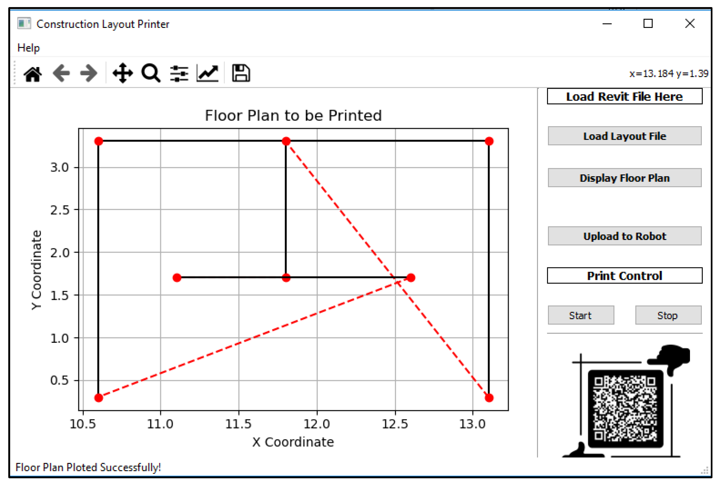
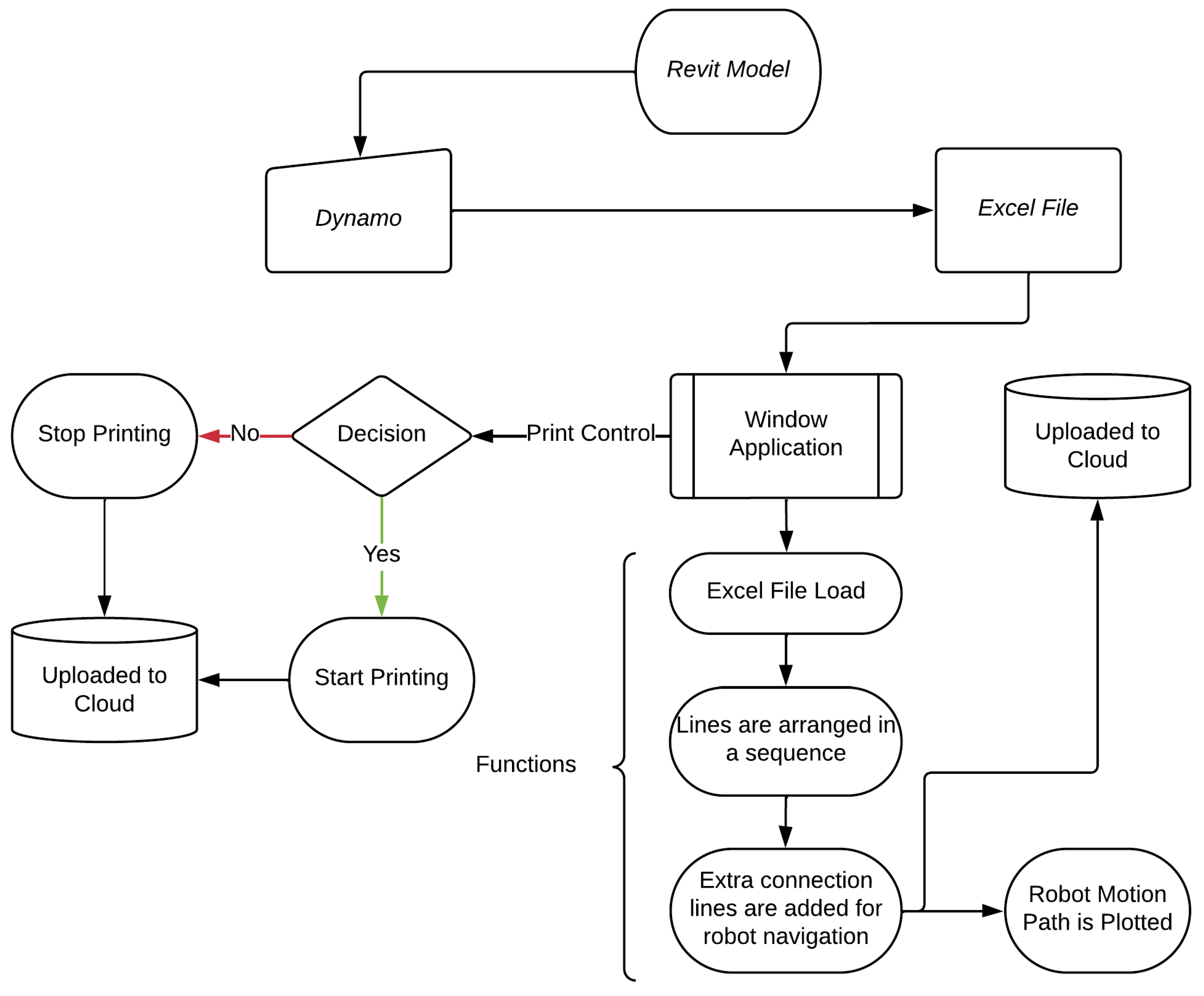
  • To address this interoperability gap for the layout marking process, the authors propose a framework for the automated extraction and analysis of floor plans from BIM models using Dynamo. The data extracted are then input into the Windows application developed in this study to determine and draw an optimal path for the IoT-powered robot. Finally, the data are uploaded to the robot via the Internet using the Firestore real-time database to draw the floor plans on an actual scale on the construction site. The proposed framework uses a set of algorithms for robotic systems to automatically perform the printing operations based on the extracted and analyzed input data from BIM. This framework will facilitate accurate and precise site layout printing operations by utilizing the information extracted from BIM models in real-time. Accordingly, the objectives of this study include:
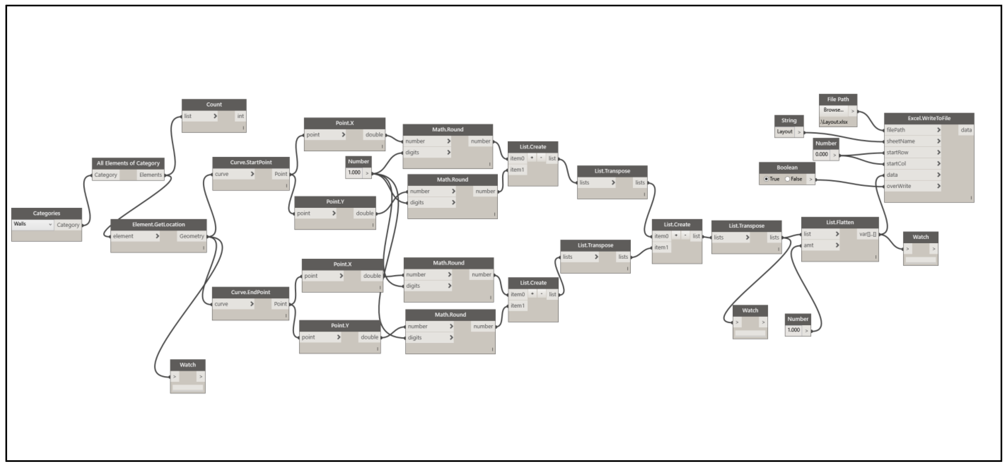
  • To extract data from BIM models using Dynamo and process it through a Windows application to establish an efficient workflow for transforming the BIM data into a format suitable for the layout printing robot.
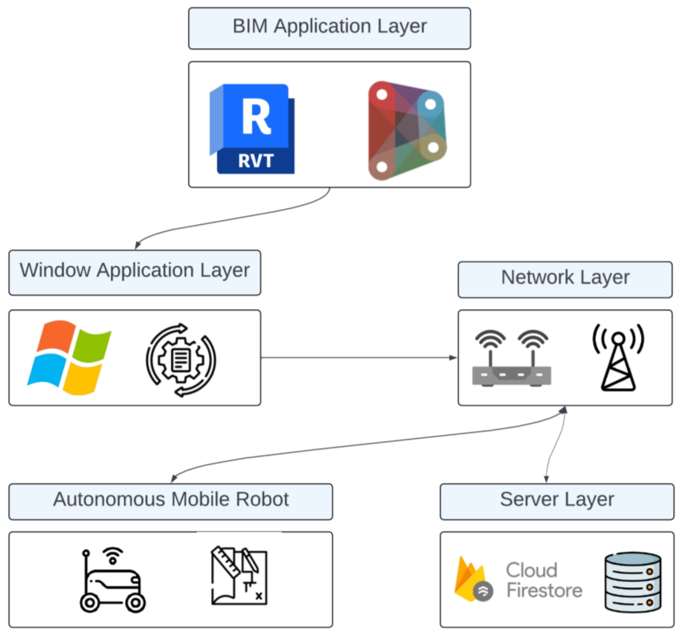
  • To develop a comprehensive framework that enables smooth communication and data exchange between BIM models and robotic systems through the IoT.
The novelty of this study lies in its comprehensive approach to addressing the challenges of construction layout printing through the integration of BIM, IoT and AMR. While previous research has explored individual aspects of construction automation or robotics in layout printing, the primary gap this study addresses is the lack of interoperability between BIM and robotics, which has hindered the full realization of the benefits of automation in construction. By developing a framework that enables seamless communication and data exchange between BIM and AMR through the IoT, this study aims to optimize the layout printing process and improve construction productivity. The integration of BIM, IoT and AMR sets this study apart from others. It highlights its importance in paving a new innovative way for the widespread adoption of automation in the construction industry, leading to enhanced project delivery and cost-effectiveness.
The proposed framework for construction layout printing has far-reaching applications and benefits across the construction sector. Firstly, large-scale construction projects, such as commercial buildings and infrastructure developments, stand to gain the most from this automation. The use of autonomous robots for precise layout printing can significantly reduce the time and effort required, leading to faster project completion and reduced labor costs. Additionally, the improved accuracy and data exchange through BIM integration can enhance project coordination and decision-making, resulting in improved project efficiency, reduced errors, minimized rework and increased cost-efficiency. Furthermore, the technology can benefit smaller construction projects and contractors, allowing them to compete more effectively and deliver high-quality results with minimum workforce and time constraints. BIM–IoT integration for the site layout process enables construction professionals to focus on more critical tasks, thus enhancing workforce productivity.
The research methodology employed in this study follows a systematic approach to comprehensively investigate the technological interoperability between BIM and RiCs with a specific focus on construction site marking. The study is initiated with the systematic literature review (SLR) method, enabling a thorough analysis of the most recent publications on the application of the BIM–IoT framework and layout marking robots. Identifying research gaps in the literature highlighted the need for a BIM–IoT framework to develop a BIM-integrated AMR for construction layout printing. Therefore, the design science research (DSR) methodology was adopted to tackle this topic [31]. Following the tenets of design science research (DSR), a creative BIM–IoT framework customized for the specific task of construction layout marking was conceived. In order to verify its feasibility and efficiency, the framework was put into action through a sequence of demonstrations and meticulously planned laboratory experiments. The results of these experiments were subsequently juxtaposed with existing research to evaluate the suitability and potential advantages of the newly introduced BIM–IoT framework. This paper is structured as follows. Section 2 presents a review of the pertinent literature and discusses relevant studies on robotics system designs and existing research in construction automation. It sets the foundation for the proposed framework’s novelty and addresses the research gap. Section 3 details the proposed approach, including BIM integration, Windows application development and the AMR design for layout printing. Section 4 presents the results of the experiments, demonstrating the accuracy and efficiency of the proposed system. Pertinent discussions and comparisons with other studies are presented in Section 5. Finally, Section 6 concludes the study, summarizes its contributions and presents the limitations and future directions of research.

2. Existing Robotic Systems for Construction Site Layout Drawings

Previous studies have attempted to achieve accurate and autonomous marking operations through AMRs. Tanaka et al. [32] developed a system that could independently navigate and draw on a ceiling board. The system had an accuracy of 10 mm and it took approximately 8 min to draw a single point. The robot relied on a laser range finder (LRF) to locate the three pillars’ margins at a building site. However, the accuracy of the markings was compromised if a pillar was too far away or if a fire-resistant material was used to cover it. Abidin et al. [33] developed a mobile robotic system for autonomous floor marking during trade fairs or exhibitions. The marking accuracy of this method was about 10 mm. The accuracy depended on a camera situated on top of the designated marking area. However, the setup was time-consuming and expensive since each installation position required the camera to be calibrated, which had to be positioned on the ceiling. The viewing field of the camera also restricted the marking area.
Another marking robot developed by Tanaka et al. [34] consisted of a mobile self-positioning robot with a drawing system. This robot was used to mark and fit the various devices on the ceiling board. In this task, the marking precision of ±10 mm was satisfactory but insufficient for building construction. Inoue et al. [35] presented a system that used an LRF and a total station to find the position of the robots. This system achieved a marking accuracy of about 2 mm and it took approximately 2 min to mark the target area once the robot reached it. However, the system was unable to gauge the mobile robot’s attitude angle while it was traveling and no reported navigation technique allowed it to move between marking sites. Kitahara et al. [19] and Lee et al. [36] presented a robotic system that could precisely draw line segments on floors and walls of construction sites with a precision of 1 mm or less. However, their setup required a human worker to move the robot via a remote command; it was not automated.
Previous studies in the field have often depended on manual operator intervention or robot position resets for each task, resulting in laborious and repetitive work, ultimately decreasing overall work productivity. Additionally, none of these studies have explored integrating the process with BIM. This presents a critical gap. Accordingly, there is a need for a novel robotic marking system that minimizes reliance on manual labor, automates repetitive tasks and allows the workforce to focus on other construction activities. Developing low-cost IoT-based robots becomes imperative to achieve this objective. Various other industries have already leveraged IoT platforms and relevant frameworks to develop navigational robots, making it a promising avenue for cost-effective and efficient robot integration in construction.
Kamarudin et al. [37] developed an IoT-based mobile robot with a line-following mechanism for an automated guided vehicle (AGV) application, controlled via a mobile app communicating through the IoT. The system used radio frequency identification (RFID) tags for location identification. Karahan et al. [38] created an IoT-based mobile robot position controlling system with Raspberry Pi, allowing users to control the robot remotely through a web-based control panel. Nafais et al. [39] designed an IoT-based intelligent cargo carrier robot capable of providing location, orientation, obstacle and surface texture information in real-time. The system also enabled remote monitoring and control and was programmed to respond intelligently to sensor-detected conditions. These projects showcase the integration of IoT technology with mobile robots, facilitating advanced functionalities suitable for various applications like logistics and warehouse automation. Nevertheless, the applications of such AMRs are limited in construction site layout drawings.

3. Research Methodology

This section presents the conceptual framework and detailed methodology adopted in this study. It provides a detailed overview of the carefully organized stages of the current research and shares implementation details of the proposed system.

3.1. Proposed Framework

The automated construction site layout printing process presented in this study involves utilizing multiple components and technologies. It includes a BIM model for generating plans [40], the development of a Windows application for processing data and an IoT-based mobile robot for printing the layout. This integrated system enables automation and streamlines the site layout printing process, offering numerous benefits such as increased efficiency, improved precision and reduced labor requirements [41]. Figure 1 presents an overview of the framework proposed for BIM–IoT integrated construction layout printing through AMRs. The proposed framework has multiple layers of operation. It includes a BIM application layer, a Windows application layer, a network layer, an AMR layer and a server layer.
The BIM model in the BIM application layer serves as the foundation for the layout printing process. It provides accurate and detailed information for different elements of floor plans and the site layout [42]. The information is extracted using Dynamo. A Windows application is also developed in the Windows application layer that plays a crucial role in processing the data extracted from the BIM model. The application serves as an intermediary between the BIM model and the mobile robot (the AMR layer), transforming the extracted information into a format suitable for printing and storing it on a cloud database (server layer). The system is connected through IoTs and networks through the network layer. The mobile robot is the physical entity responsible for drawing the layout of the construction site.

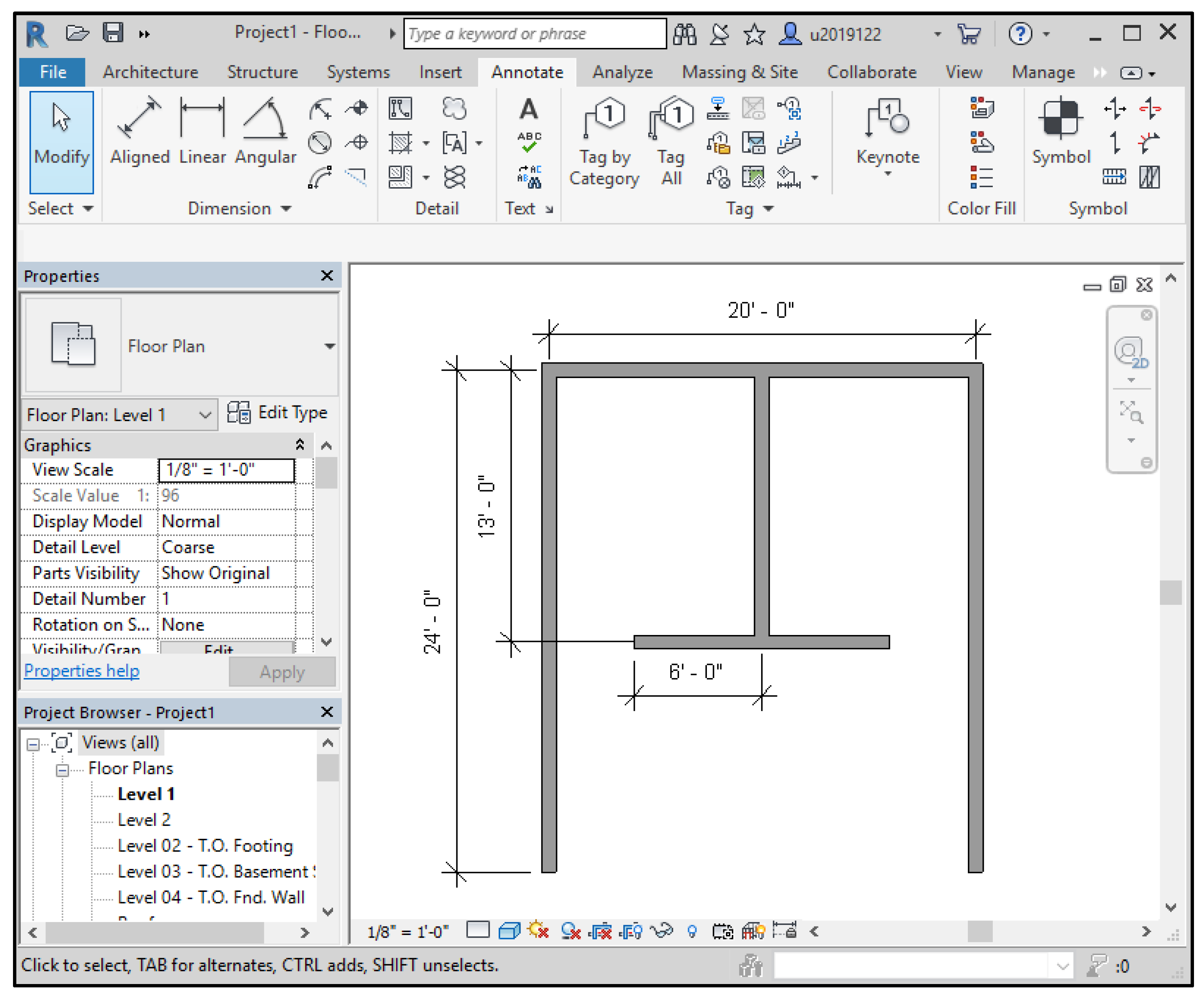
3.2. BIM Model and Information Extraction

In this study, a BIM model was developed using Revit 2018 [41]. The model consisted of a floor plan of 480 ft2 as depicted in Figure 2 [43]. The floor plan consisted of two rooms of 10 × 13 ft with a window of width 4ft and a Veranda of 20 × 11 ft. For testing purposes, the floor plan was scaled down by 1:8. The floor plan serves as the basis for extracting the necessary data from the Revit model. To extract the data from the floor plan, the coordinates of the start and end points of elements were obtained using Dynamo, a visual programming tool for Revit [44,45]. These coordinates were then stored in a local file stored on the desktop.
Extracting coordinates using Dynamo enables the collection of precise information about the elements in the floor plan, specifically walls and windows. The Dynamo script adopted in this study is shown in Figure 3. Critical data related to the positioning and dimensions of walls and other site features can be obtained by accessing the start and end points of these elements. This information is essential for accurately replicating the layout on the construction site. The current model extracts data for walls and windows only; however, it can be extended to other features with start and end coordinates.

3.3. Developed Windows Application

In addition to developing the BIM model and extracting data from Revit, a Windows-based application was also developed to process the extracted data and upload it to a cloud platform for the mobile robot to access. The user interface of the developed window application, which provides a user-friendly environment for data processing, can be seen in Figure 4. The application was developed using Python, leveraging PyQt, Firestore and Matplotlib to enhance its functionality. The developed application has various features, such as loading the Revit file, loading layouts, displaying floor plans and uploading the plans to the robot. It also instructs the robots on when to print the layout through the print control function. The x and y coordinates can be changed or varied in the application through various tools where needed.
To design the user interface of the window application, the PyQt library was utilized. Qt Designer is a powerful tool that allows developers to create interactive and visually appealing graphical user interfaces [46]. Firebase’s Firestore feature provides the necessary remote data access and storage functionality. This integration allows seamless communication between the Windows application and the cloud platform, enabling efficient and convenient availability of the extracted data for subsequent analysis and utilization by the mobile robot [47]. Furthermore, for the visualization of the data collected from the Revit model in the Windows application, the Matplotlib library was utilized [48]. The overall data flow in the Windows application can be seen in Figure 5.
In the developed Windows application, coordinates of the wall elements are extracted by Dynamo and stored in a local file. These coordinates are imported into the robot. The Windows application sorts the coordinates based on their starting points and proximity. It adds virtual navigation lines to bridge gaps, ensuring the robot’s smooth movement without printing additional lines. The robot’s path is displayed on the screen to ensure it follows the Revit model and finally, the data are stored on the Firestore cloud. The free tier of Firebase Cloud provides 1 GB of space, allowing for 20,000 document writes and 50,000 document reads per day. The usage limit can be increased by opting for premium tiers [49]. The Windows application also enables users to start or stop the robot remotely when new floor plans are sent for navigation. This streamlined data flow simplifies the process, enabling efficient robot navigation in complex environments.

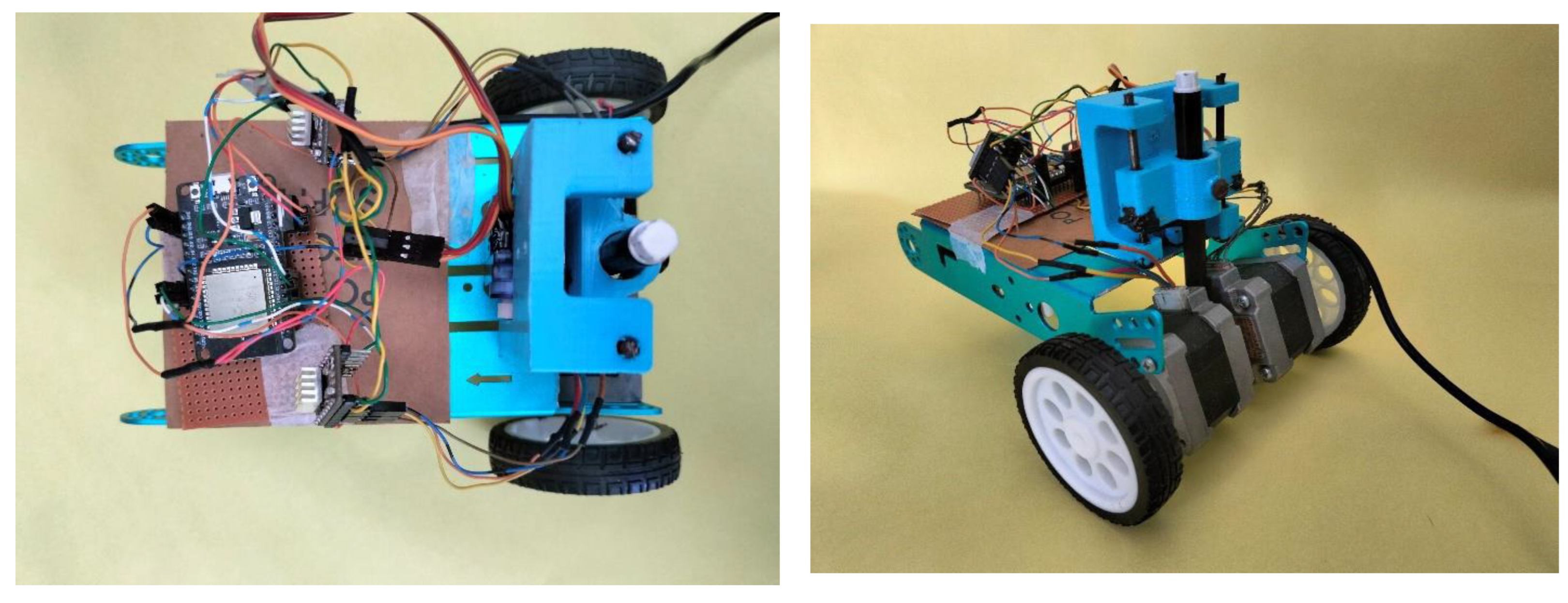
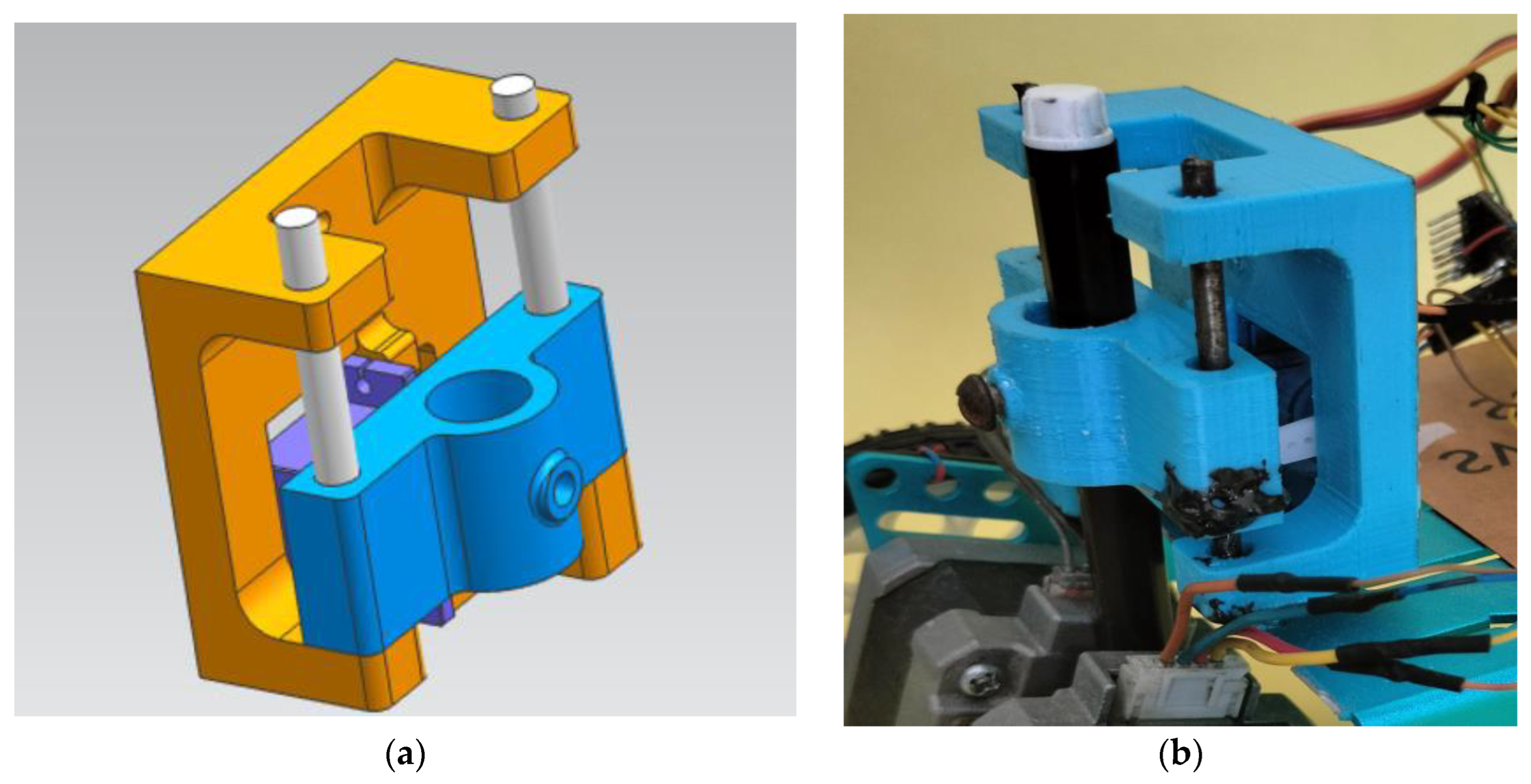
3.4. Proposed Robotic System Design
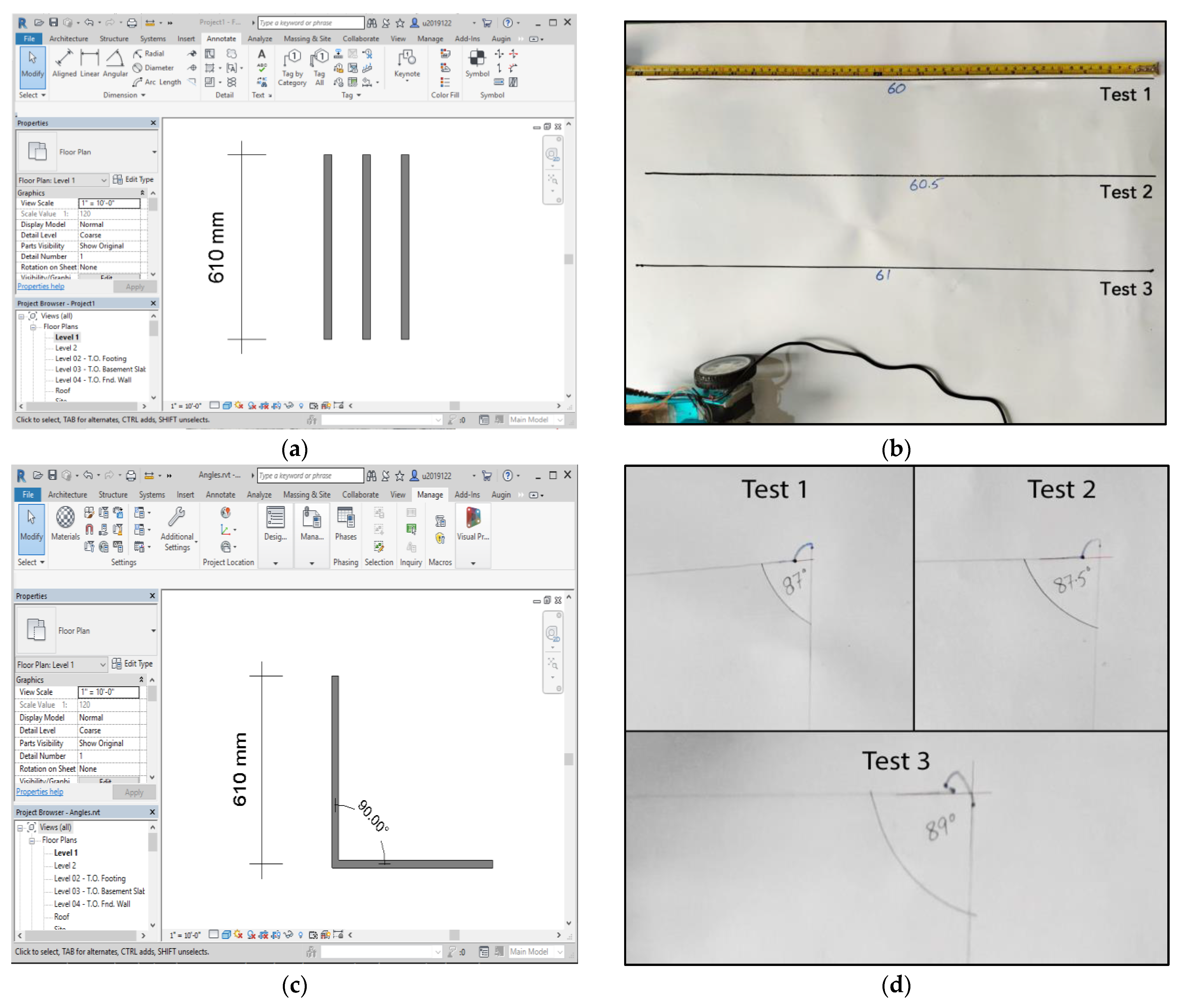
The robot developed for this study is based on the studies of Inoue et al. [50] and Tanaka et al. [32]. The developed mobile robot consists of two main components, as illustrated in Figure 6. These include a robot with a self-position measurement system and a marking system. The robot utilizes odometry for localization based on the input coordinates. The mobile system is equipped with two independent driving wheels and a caster wheel, allowing it to navigate toward the target point using BIM data stored on the cloud. By utilizing the rotational angles of its driving wheels, the robot employs dead reckoning to follow its predetermined path. A benchpoint is needed for the robot to initiate the layout printer. This can be set through the survey point of the BIM model. The robot makes minor adjustments to ensure positional accuracy at the first start if necessary. With the designated point confirmed, the lifting system activates the marking system, enabling the robot to draw the desired layout on the floor. This process continues until all floor markings are completed.
The robot’s physical specifications include a length of 200 mm, a width of 95 mm and a variable height ranging from 170 mm to 200 mm. It has a total weight of 4 kg. Its development is based on using ESP32, a versatile microcontroller, combined with two NEMA 17 stepper motors, each integrated with DRV8825 stepper motor drivers to facilitate precise movement. Additionally, the robot’s marking tool is equipped with an SG 90 servo motor for the linear motion of movable assembly.
The marking device of the mobile robot developed in the current study has a special pen holder module designed especially for the computer numerical control (CNC) plotter [51]. It consists of two parts, as shown in Figure 7. One part is fixed and attached to the robot chassis, holding a servo motor. The other part is movable and holds the marker. During the operation, the marker is lowered when the robot moves along the path to be marked. The marker is subsequently raised when the robot needs to move to a different location for navigation. This way, the robot can accurately mark its path when needed and avoid unnecessary marking, thus ensuring efficient and safe operation. The module used in the developed marking device was 3D printed with 50% density to have significant strength to push the pen so that the layout can also be drawn on rough surfaces.
In this study, a permanent marker was attached to the movable part of the marking device to draw the mentioned floor plan on a leveled surface of ceramic tile. The attached servo motor pushes the marker to touch the surface when the line needs to be drawn. The force applied by the servo motor is restricted to avoid causing any disturbance to the motion of the robot. Although the proposed marking assembly may not work on uneven, rough surfaces or soils, the robot can still be utilized with a different marking device, i.e., chalk powder, to adapt to various surfaces [52].
One of the primary challenges when implementing an IoT-based framework is ensuring security to prevent cyberattacks and data misuse. The proposed framework incorporates the Firebase Authentication and Authorization mechanism [53]. The Firestore security rules meticulously control data access, specifying who can read and write data. Furthermore, the sensors are programmed using the “Firebase_ESP_Client.h” library, which offers built-in security features, guaranteeing secure data transmission from the sensor to the database. This library prioritizes user privacy and data protection, adhering to Google’s stringent authentication processes.

4. System Testing

Different sets of experiments were conducted to test the developed robotic system based on the proposed framework for drawing construction site layouts. In the first set of experiments, the lengths of lines were drawn and the robot’s performance was evaluated. For length evaluation, three straight lines of 61 cm in length were drawn in Revit, as shown in Figure 8a. The robot was then deployed to draw these lines on a B2 sheet of paper placed on a concrete floor. On average, each 61 cm line was marked in approximately 8 s and the accuracy achieved was within ±1 cm. The results of the robot’s markings can be observed in Figure 8b. In the next step, three L-shaped lines were also drawn to assess the accuracy of the angle drawn by the robot, as shown in Figure 8c,d. The accuracy of the angle drawn by the robot ranged within ±4 degrees. These tests were performed inside a lab on a smooth surface. The experiments were repeated several times for initial calibration until the most accurate results were obtained.
In another experiment, the scaled floor plan prepared in Revit (see Figure 9a) was uploaded to the cloud after processing. Both straight lines and corners were included in the floor plan to determine both the linear and angular accuracy of the robotic drawings. The developed robot was placed on a plane surface of ceramic tiles and the layout from the cloud was input to the robot for pertinent drawings, as shown in Figure 9b. The accuracy of the drawn layout was cross-checked in the experiment by manually measuring the lines and angles drawn by the robot. The layout was drawn in less than 5 min with a line accuracy of 1.5 cm and angle accuracy of ±3 degrees.
In the first set of experiments conducted in a controlled environment, the results obtained were highly accurate compared to the second set of experiments performed on ceramic tiles. This discrepancy suggests that the surface on which the robot moves can significantly impact its accuracy. Despite the overall efficiency of the experiment, a few issues arose during the first trial, notably a power outage that caused the robot to lose its location information, requiring it to restart the entire process from the beginning. Additionally, an error can also be seen at the cross of the L-shaped line where the end point of the line does not coincide with the starting point of the next line. This error is due to the lateral motion of the marking device that results in higher linear lengths in the second experiment. The robot requires the marking device to be located in the center of the axle of the wheel so that during turning or rotation, the marking point does not change.

5. Discussion

Automating the site layout marking process can reduce reliance on manual labor and minimize the potential for human error. This may eventually lead to an improvement in workers’ productivity. The use of robotics in construction offers several advantages [54]. Firstly, it significantly speeds up the layout marking process, allowing construction projects to progress faster with increased accuracy and safety in precision working. With automation, the mobile robot can swiftly navigate the construction site and print multiple layout markings faster than manual methods.
Automation improves the precision and accuracy of layout printing. Human error and associated variations in worker skill levels can lead to discrepancies between the on-site layout and the blueprint. However, with the integration of robotics and the precise data extracted from the BIM model as proposed in the current study, the mobile robot may strengthen the sustainability of innovation and the digital transformation process as a whole and can consistently apply the layout markings with high accuracy, minimizing errors and ensuring adherence to the design specifications [55].
Furthermore, the automation of the layout printing process frees up human resources to focus on other critical construction tasks. By delegating the labor-intensive and time-consuming task of layout printing to the mobile robot, construction workers can dedicate their time and expertise to more complex and value-adding activities. This increases productivity and efficiency within the construction site, leading to positive economic long-term effects [56]. The use of the layout printing robot may not be limited to building construction; rather, it can be adapted for a wide range of applications, including traffic signs and symbol printing on the road.
The current study demonstrates superior results compared to several other systems presented by Jensfelt et al. [17], Tsuruta et al. [20], Lee et al. [36] and Kitahara et al. [19] as shown in Table 1. The current study achieves an accuracy of 10 mm and completes the layout marking task in 8 s, showcasing a fully automated process with BIM–IoT integration. In contrast, the systems presented in the above studies exhibit lower accuracy values ranging from 2.3 mm to 28 mm and take longer to complete the task, with values ranging from 33 s to 98 s. The degree of automation in the other systems varies, with some being semiautomated, requiring an on-site operator to set up the mobile robot and load the floor plan. Similarly, the manual systems need an operator to control the robot’s motion on-site using a joystick/controller. In comparison, the current study presents a completely automated process utilizing the IoT framework; the robot can be controlled remotely.
The current study uses a BIM-integrated model. In comparison, the other systems do not use BIM integration for precise data extraction. Although the system developed by Jensfelt et al. [17] uses 2D CAD drawings manually uploaded to the robot, such manual models cause an additional error of up to 2 cm. The current study’s automated approach offers advantages in terms of speed, precision and accuracy, reducing reliance on manual labor, minimizing human errors and allowing construction workers to focus on more critical tasks. Compared to manual methods, AMRs presented in the current study can reduce the time of layout marking by almost 50% [17].
The cost of a simple robot developed based on ESP32 and NEMA 17 for developing countries is significantly lower compared to the robots mentioned in the studies above. The mentioned studies involved the development of specialized robotic systems for specific tasks, such as ceiling board marking and floor marking, using advanced technologies like laser range finders, cameras and total stations. These specialized systems often require expensive components and complex setups, leading to higher development costs. In contrast, the ESP32 and NEMA 17 based robot would be a more straightforward and cost-effective solution due to the simplicity of its design and the affordability of its components. By leveraging IoT-based platforms and frameworks, the development of the ESP32 and NEMA 17 based robot can be further streamlined, making it an attractive and economically viable option for construction applications in developing countries.

6. Conclusions, Limitations and Future Directions

This study investigates the potential integration of RiC with BIM in addressing real-world challenges, with a focus on enhancing the efficiency of construction layout marking. Through the integration of robotics, IoT and BIM, a comprehensive framework has been proposed in this study to enable seamless communication and data exchange between BIM models and robotic systems. A prototype robot was developed that facilitates accurate and precise printing operations based on extracted information from BIM, resulting in increased efficiency, improved precision and reduced reliance on manual labor. The need for improved interoperability between BIM and robotics, as well as the adoption of robotics in the construction sector, is also highlighted in this study. The proposed methodology aims to bridge these gaps by providing an integrated system that combines BIM data extraction, Windows application processing and IoT-powered mobile robot printing. The developed automation system has the potential to enhance productivity, accuracy and efficiency in the site layout printing process, freeing up construction workers for more complex tasks and minimizing errors associated with human factors. Moreover, the minimized dependency on manual labor can decrease workplace accidents and health risks associated with physically demanding tasks, ultimately contributing to improved worker well-being. In addition, the AMRs have zero to no carbon emissions compared to other techniques and heavy equipment used on construction sites. Therefore, these will help reduce the carbon footprints of construction site layout activities [57]. Similarly, the usage of advanced technologies will help in the smoother integration of construction activities into society in line with modern smart cities and society endeavors [58].
The BIM–IoT framework devised within the scope of this study stands as a proof of concept. One of the potential challenges in the adoption of the BIM–IoT framework is the limitations in data transfer capacity and data security. This study uses encryption and authentication to enhance data protection and flow. However, there are other limitations that need to be addressed in future research. For example, while mostly automated, it extracts data from the BIM model using Dynamo. The local file created by Dynamo is then imported into the Windows application; thus, the system includes a few manual steps. Hence, the system cannot be recognized as a real-time automated system but rather as a nearly real-time system. Moreover, using an Arduino device, such as the ESP32, to operate an AMR with stepper motors can be an excellent choice, but there are certain limitations related to the execution of instructions that can affect the simultaneous control of both motors. The Arduino executes instructions sequentially, one line at a time, which can introduce challenges for coordinating the movement of multiple motors. This delay is in microseconds; hence, it is not significant, but the Arduino-based AMR may not be the best choice for extremely high accuracy. Furthermore, the robot developed in this study does not sense the environment in terms of surfaces and obstacles; plain surfaces were used to test the robot. The accuracy of the robot may result differently as odometry results are prone to surface slippage or wheel malfunctioning, in which the error accumulates with time. This may restrict its usage on uneven surfaces, which are not uncommon on construction sites.
Further advancements in the real-time operation and precision of the AMRs could be explored in future research. Some recommendations include streamlining the data extraction process from the BIM model by exploring automated methods that minimize manual steps. Further enhancing the real-time capabilities and addressing the limitations of the Arduino device, such as the ESP32, will improve coordination and ensure smooth movement of the AMRs. This can be achieved by controlling multiple stepper motors simultaneously using alternative hardware or programming techniques. In addition, the advancements in relation to Industry 5.0 endeavors can also be explored in future studies.

Author Contributions

Conceptualization, F.I., S.A., S.Q., F.A. and F.U.; methodology, F.I., S.A., F.A., S.Q. and F.U.; software, F.I.; validation, F.I., S.A., S.Q., F.A. and F.U.; formal analysis, F.I., S.A., S.Q., F.A. and F.U.; investigation, F.I., S.A., S.Q., F.A. and F.U.; resources, F.U. and S.Q.; data curation F.I., S.A. and F.A.; writing—original draft preparation, F.I. and F.A.; writing—review and editing, S.Q., S.A. and F.U.; visualization, F.A.; supervision, S.A., S.Q. and F.U.; project administration, S.Q., S.A. and F.U.; funding acquisition, F.U. and S.Q. All authors have read and agreed to the published version of the manuscript.

Funding

This research received no external funding.

Data Availability Statement

The data and codes used in this study are available from the first author and can be shared upon reasonable request.

Acknowledgments

The authors acknowledge the design of the marking system developed by Trần Luân under open access and the developers of Firebase-ESP-Client Library for esp32 that have been utilized in the current study.

Conflicts of Interest

The authors declare no conflict of interest.

References

  1. Chen, Q.; García de Soto, B.; Adey, B.T. Construction Automation: Research Areas, Industry Concerns and Suggestions for Advancement. Autom. Constr. 2018, 94, 22–38. [Google Scholar] [CrossRef]
  2. Changali, S.; Mohammad, A.; Van Nieuwland, M. The Construction Productivity Imperative. In McKinsey Quarterly; McKinsey: New York, NY, USA, 2015. [Google Scholar]
  3. Ma, X.; Mao, C.; Liu, G. Can Robots Replace Human Beings?—Assessment on the Developmental Potential of Construction Robot. J. Build. Eng. 2022, 56, 104727. [Google Scholar] [CrossRef]
  4. Haas, C.; Skibniewski, M.; Budny, E. Robotics in Civil Engineering. Comput. Aided Civ. Infrastruct. Eng. 1995, 10, 371–381. [Google Scholar] [CrossRef]
  5. García de Soto, B.; Agustí-Juan, I.; Hunhevicz, J.; Joss, S.; Graser, K.; Habert, G.; Adey, B.T. Productivity of Digital Fabrication in Construction: Cost and Time Analysis of a Robotically Built Wall. Autom. Constr. 2018, 92, 297–311. [Google Scholar] [CrossRef]
  6. Streule, T.; Miserini, N.; Bartlomé, O.; Klippel, M.; de Soto, B.G. Implementation of Scrum in the Construction Industry. Procedia Eng. 2016, 164, 269–276. [Google Scholar] [CrossRef]
  7. Kim, K.P.; Freda, R.; Nguyen, T.H.D. Building Information Modelling Feasibility Study for Building Surveying. Sustainability 2020, 12, 4791. [Google Scholar] [CrossRef]
  8. Ullah, F. (Ed.) Towards Smart Tech 4.0 in the Built Environment: Applications of Disruptive Digital Technologies in Smart Cities, Construction, and Real Estate; MDPI: Basel, Switzerland, 2023; ISBN 978-3-0365-7355-7. [Google Scholar]
  9. Amini, S.; Rezvani, A.; Tabassi, M.; Malek Sadati, S.S. Causes of Cost Overruns in Building Construction Projects in Asian Countries; Iran as a Case Study. Eng. Constr. Archit. Manag. 2022, 30, 2739–2766. [Google Scholar] [CrossRef]
  10. Taha, G.; Sherif, A.; Badawy, M. Overall Cost Overrun Estimate in Residential Projects: A Hybrid Dynamics Approach. Appl. Comput. Intell. Soft Comput. 2022, 2022, 2285971. [Google Scholar] [CrossRef]
  11. Propeller Aero 10 Construction Project Cost Overrun Statistics You Need to Hear. Available online: https://www.propelleraero.com/blog/10-construction-project-cost-overrun-statistics-you-need-to-hear/ (accessed on 25 July 2023).
  12. Dobbs, R.; Pohl, H.; Lin, D.-Y.; Mischke, J.; Garemo, N.; Hexter, J.; Matzinger, S.; Palter, R.; Nanavatty, R. Infrastructure Productivity: How to Save $1 Trillion a Year; McKinsey Global Institute: New York, NY, USA, 2013. [Google Scholar]
  13. Williams, B. The Real Cost of Inefficient Construction Layout. Available online: https://constructible.trimble.com/construction-industry/the-real-cost-of-inefficient-construction-layout (accessed on 25 July 2023).
  14. AGC Construction Workforce Shortages Risk Undermining Infrastructure Projects as Most Contractors Struggle to Fill Open Positions. Available online: https://www.agc.org/news/2022/08/31/construction-workforce-shortages-risk-undermining-infrastructure-projects-most-contractors-struggle-0 (accessed on 25 July 2023).
  15. Sestras, P. Methodological and On-Site Applied Construction Layout Plan with Batter Boards Stake-out Methods Comparison: A Case Study of Romania. Appl. Sci. 2021, 11, 4331. [Google Scholar] [CrossRef]
  16. Zhao, J.; Hu, Y.; Tian, M. Pose Estimation of Excavator Manipulator Based on Monocular Vision Marker System. Sensors 2021, 21, 4478. [Google Scholar] [CrossRef]
  17. Jensfelt, P.; Gullstrand, G.; Förell, E. A Mobile Robot System for Automatic Floor Marking. J. Field Robot. 2006, 23, 441–459. [Google Scholar] [CrossRef]
  18. Peter, E.; Love, D.; Heng, L.I. Quantifying the Causes and Costs of Rework in Construction. Constr. Manag. Econ. 2000, 18, 479–490. [Google Scholar] [CrossRef]
  19. Kitahara, T.; Satou, K.; Onodera, J. Marking Robot in Cooperation with Three-Dimensional Measuring Instruments. In Proceedings of the ISARC 2018—35th International Symposium on Automation and Robotics in Construction and International AEC/FM Hackathon: The Future of Building Things, Berlin, Germany, 22 July 2018. [Google Scholar]
  20. Tsuruta, T.; Miura, K.; Miyaguchi, M. Mobile Robot for Marking Free Access Floors at Construction Sites. Autom. Constr. 2019, 107, 102912. [Google Scholar] [CrossRef]
  21. Anane, W.; Iordanova, I.; Ouellet-Plamondon, C. Building Information Modeling (BIM) and Robotic Manufacturing Technological Interoperability in Construction—A Cyclic Systematic Literature Review. Digit. Manuf. Technol. 2023, 3, 1–29. [Google Scholar] [CrossRef]
  22. Biancardo, S.A.; Gesualdi, M.; Savastano, D.; Intignano, M.; Henke, I.; Pagliara, F. An Innovative Framework for Integrating Cost-Benefit Analysis (CBA) within Building Information Modeling (BIM). Socioecon Plann Sci 2023, 85, 101495. [Google Scholar] [CrossRef]
  23. Zhang, J.; Luo, H.; Xu, J. Towards Fully BIM-Enabled Building Automation and Robotics: A Perspective of Lifecycle Information Flow. Comput. Ind. 2022, 135, 103570. [Google Scholar] [CrossRef]
  24. Schöberl, M.; Huber, A.; Kreppold, S.; Dirnaichner, J.; Kessler, S.; Fottner, J. Cobot Uptake in Construction: Embedding Collaborative Robots in Digital Construction Processes. Constr. Robot. 2023, 7, 89–103. [Google Scholar] [CrossRef]
  25. Xiao, B.; Chen, C.; Yin, X. Recent Advancements of Robotics in Construction. Autom. Constr. 2022, 144, 104591. [Google Scholar] [CrossRef]
  26. Munawar, H.S.; Ullah, F.; Heravi, A.; Thaheem, M.J.; Maqsoom, A. Inspecting Buildings Using Drones and Computer Vision: A Machine Learning Approach to Detect Cracks and Damages. Drones 2022, 6, 5. [Google Scholar] [CrossRef]
  27. Abdeen, F.N.; Gunatilaka, R.N.; Sepasgozar, S.M.E.; Edwards, D.J. The Usability of a Novel Mobile Augmented Reality Application for Excavation Process Considering Safety and Productivity in Construction. Constr. Innov. 2022, in press. [Google Scholar] [CrossRef]
  28. Manuel Davila Delgado, J.; Oyedele, L. Robotics in Construction: A Critical Review of the Reinforcement Learning and Imitation Learning Paradigms. Adv. Eng. Inform. 2022, 54, 101787. [Google Scholar] [CrossRef]
  29. Ullah, F. Smart Tech 4.0 in the Built Environment: Applications of Disruptive Digital Technologies in Smart Cities, Construction, and Real Estate. Buildings 2022, 12, 1516. [Google Scholar] [CrossRef]
  30. Yahya, M.Y.B.; Lee Hui, Y.; Yassin, A.B.M.; Omar, R.; Robin, R.O.A.; Kasim, N. The Challenges of the Implementation of Construction Robotics Technologies in the Construction. In MATEC Web of Conferences; EDP Sciences: Yu Lisi, UK, 2019; Volume 266. [Google Scholar] [CrossRef]
  31. Anane, W.; Iordanova, I.; Ouellet-Plamondon, C. BIM-Driven Computational Design for Robotic Manufacturing in off-Site Construction: An Integrated Design-to-Manufacturing (DtM) Approach. Autom. Constr. 2023, 150, 104782. [Google Scholar] [CrossRef]
  32. Tanaka, K.; Kajitani, M.; Kanamori, C.; Itoh, H.; Abe, Y.; Tanaka, Y. Development of Marking Robot Working at Building Sites. In Proceedings of the 12th International Symposium on Automation and Robotics in Construction (ISARC), Warsaw, Poland, 30 May–1 June 1995. [Google Scholar]
  33. Abidin, Z.Z.; Hamid, S.B.A.; Aziz, A.A.A.; Ab Malek, A. Development of a Vision System for a Floor Marking Mobile Robot. In Proceedings of the 2008 Fifth International Conference on Computer Graphics, Imaging and Visualisation, Modern Techniques and Applications, CGIV, Penang, Malaysia, 26–28 August 2008. [Google Scholar]
  34. Tanaka, K.; Kajitani, M.; Ito, H.; Kanamori, C.; Abe, Y.; Tanaka, Y. Development of a Construction Robot for Marking on Ceiling Boards. Nippon. Kikai Gakkai Ronbunshu C Hen/Trans. Jpn. Soc. Mech. Eng. Part C 1996, 62, 658–664. [Google Scholar] [CrossRef]
  35. Inoue, F.; Doi, S.; Omoto, E. Development of High Accuracy Position Making System Applying Mark Robot in Construction Site. In Proceedings of the SICE Annual Conference, Tokyo, Japan, 13–18 September 2011. [Google Scholar]
  36. Lee, A.Y.; Seo, H.C.; Park, E.S. Development of a Manually Operated Mobile Robot That Prints Construction Site Layouts. Machines 2022, 10, 1192. [Google Scholar] [CrossRef]
  37. Kamarudin, K. Development of IoT Based Mobile Robot for Automated Guided Vehicle Application. J. Electron. Inf. Syst. 2019, 1. [Google Scholar] [CrossRef]
  38. Karahan, O.; Hökelek, H. Mobile Robot Position Controlling System Based On IoT Through Raspberry Pi. J. Intell. Syst. Theory Appl. 2020, 3, 25–30. [Google Scholar] [CrossRef]
  39. Suhana Nafais, A.; Cibi, S.L.; Harish Kumar, A.; Tharani, M.; Viswak Avinash, S.P. An IoT Based Intelligent Cargo Carrier. In Proceedings of the 2023 7th International Conference on Intelligent Computing and Control Systems (ICICCS), Madurai, Tamil Nadu, 17–19 May 2023; IEEE: Piscataway Township, NJ, USA, 2023; pp. 1569–1574. [Google Scholar]
  40. Tao, G.; Feng, H.; Feng, J.; Wang, T. Dynamic Multi-Objective Construction Site Layout Planning Based on BIM. KSCE J. Civ. Eng. 2022, 26, 1522–1534. [Google Scholar] [CrossRef]
  41. Tang, S.; Shelden, D.R.; Eastman, C.M.; Pishdad-Bozorgi, P.; Gao, X. A Review of Building Information Modeling (BIM) and the Internet of Things (IoT) Devices Integration: Present Status and Future Trends. Autom. Constr. 2019, 101, 127–139. [Google Scholar] [CrossRef]
  42. Al Hawarneh, A.; Bendak, S.; Ghanim, F. Construction Site Layout Planning Problem: Past, Present and Future. Expert Syst. Appl. 2021, 168, 114247. [Google Scholar] [CrossRef]
  43. Revit® Architecture 2018 for Designers; Bloomsbury Publishing Plc: New York, NY, USA, 2017; ISBN 978-1-5013-2773-5.
  44. Divin, N.V. BIM by Using Revit API and Dynamo: A Review. AlfaBuild 2020, 14, 1404. [Google Scholar]
  45. Kensek, K.M. Integration of Environmental Sensors with BIM: Case Studies Using Arduino, Dynamo, and the Revit API. Inf. De La Constr. 2014, 66. [Google Scholar] [CrossRef]
  46. Liu, Q.; Qiao, Z.; Lv, Y. PyVT: A Python-Based Open-Source Software for Visualization and Graphic Analysis of Fluid Dynamics Datasets. Aerosp. Sci. Technol. 2021, 117, 106961. [Google Scholar] [CrossRef]
  47. Singh, S.; Verma, S.; Kumar, S.; Kumar Singh, S. Home Automation Using Node MCU, Firebase & IOT. Int. J. Sci. Res. Rev. 2019, 7, 1289–1294. [Google Scholar]
  48. Hunter, J.; Dale, D.; Firing, E.; Droettboom, M. Matplotlib: Visualization with Python. Available online: https://matplotlib.org (accessed on 2 July 2023).
  49. Sukmana, Y.; Rosmansyah, Y. The Use of Cloud Firestore for Handling Real-Time Data Updates: An Empirical Study of Gamified Online Quiz. In Proceedings of the 2021 2nd International Conference on Electronics, Communications and Information Technology, CECIT 2021, Sanya, China, 27 December 2021. [Google Scholar]
  50. Inoue, F.; Ohmoto, E. High Accuracy Position Marking System Applying Mobile Robot in Construction Site. J. Robot. Mechatron. 2012, 24, 985–991. [Google Scholar] [CrossRef]
  51. Trần Luân Pen Holder for Drawing Machine. Available online: https://www.thingiverse.com/thing:5505579 (accessed on 8 July 2023).
  52. Park, E.S.; Seo, H.C.; Lee, A.Y. Development of a Multi-Layer Marking Toolkit for Layout-Printing Automation at Construction Sites. Sensors 2022, 22, 4822. [Google Scholar] [CrossRef]
  53. Hlaing, K.M.; Nyaung, D.E. Electricity Billing System Using Ethereum and Firebase. In Proceedings of the 2019 International Conference on Advanced Information Technologies, ICAIT 2019, Yangon, Myanmar, 6–7 November 2019. [Google Scholar]
  54. Soffar, H. Robotics, Automation in Construction Uses, Advantages & Disadvantages|Science Online. Available online: https://www.online-sciences.com/robotics/robotics-automation-in-construction-uses-advantages-disadvantages/ (accessed on 24 July 2023).
  55. Faghihi, V.; Nejat, A.; Reinschmidt, K.F.; Kang, J.H. Automation in Construction Scheduling: A Review of the Literature. Int. J. Adv. Manuf. Technol. 2015, 81, 1845–1856. [Google Scholar] [CrossRef]
  56. Park, J.K.; Lee, K.W. Efficiency Analysis of Construction Automation Using 3D Geospatial Information. Sens. Mater. 2022, 34, 415–425. [Google Scholar] [CrossRef]
  57. Šlajpah, S.; Munih, M.; Mihelj, M. Mobile Robot System for Selective Asparagus Harvesting. Agronomy 2023, 13, 1766. [Google Scholar] [CrossRef]
  58. Sepasgozar, S.M.E.; Khan, A.A.; Smith, K.; Romero, J.G.; Shen, X.; Shirowzhan, S.; Li, H.; Tahmasebinia, F. BIM and Digital Twin for Developing Convergence Technologies as Future of Digital Construction. Buildings 2023, 13, 441. [Google Scholar] [CrossRef]
Figure 1. Overview of the proposed framework.
Buildings 13 02212 g001
Figure 2. Revit floor plan.
Buildings 13 02212 g002
Figure 3. Dynamo script for automation of data extraction from the Revit file.
Buildings 13 02212 g003
Figure 4. Developed window application for layout printing through the robot.
Buildings 13 02212 g004
Figure 5. Dataflow diagram of the window application.
Buildings 13 02212 g005
Figure 6. Developed mobile robot for layout printing.
Buildings 13 02212 g006
Figure 7. Marking tool (a). 3D CAD Model (b). Actual 3D-printed model with servo motor and pen mounted.
Buildings 13 02212 g007
Figure 8. (a) Lines drawn in the Revit. (b) Lines drawn on site by the robot. (c) Angled lines in Revit. (d) Lines drawn on site by the robot.
Buildings 13 02212 g008
Figure 9. (a) Floor plan model in Revit. (b) Layout of the drawing printer by the robot.
Buildings 13 02212 g009
Table 1. Comparison of the proposed marking robotic system with other studies.
StudyAccuracyTimeDegree of
Automation
WeightBIM
Integration
Current Study15 mm8 s Automated4 KgYes
System Presented by Jensfelt et al. [17]28 mm33 sSemi-AutomatedUnknownNo
System Presented by Tsuruta et al. [20] 2.3 mm98 sSemi-Automated17 KgNo
System Presented by Lee et al. [36]UnknownUnknownManualUnknownNo
System Presented by Kitahara et al. [19] <1 mmUnknownManual56 KgNo
Disclaimer/Publisher’s Note: The statements, opinions and data contained in all publications are solely those of the individual author(s) and contributor(s) and not of MDPI and/or the editor(s). MDPI and/or the editor(s) disclaim responsibility for any injury to people or property resulting from any ideas, methods, instructions or products referred to in the content.

