

Analytical Solution for Longitudinal Anti-Push Stiffness of the Middle Tower of Cross-Cable Multi-Tower Cable-Stayed Bridge
Abstract
:1. Introduction
2. Derivation of the Analytical Formula
- (1)
- Under the action of live load, the deformation of the bridge tower and stay cable is small; thus, it is assumed that the inclination angle of the cable does not change.
- (2)
- The cable material is linearly elastic. Consider that the deformation of the cable is elastic elongation.
- (3)
- No longitudinal drift of the main beam.
- (4)
- Ignore the axial deformation of the beam and the compression deformation of the tower.
- (5)
- The horizontal displacement of the side tower is so small that it is ignored.
- (1)
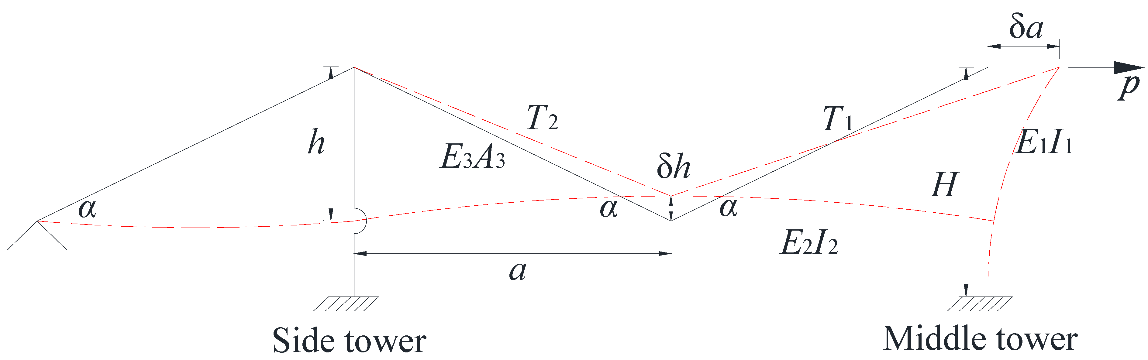
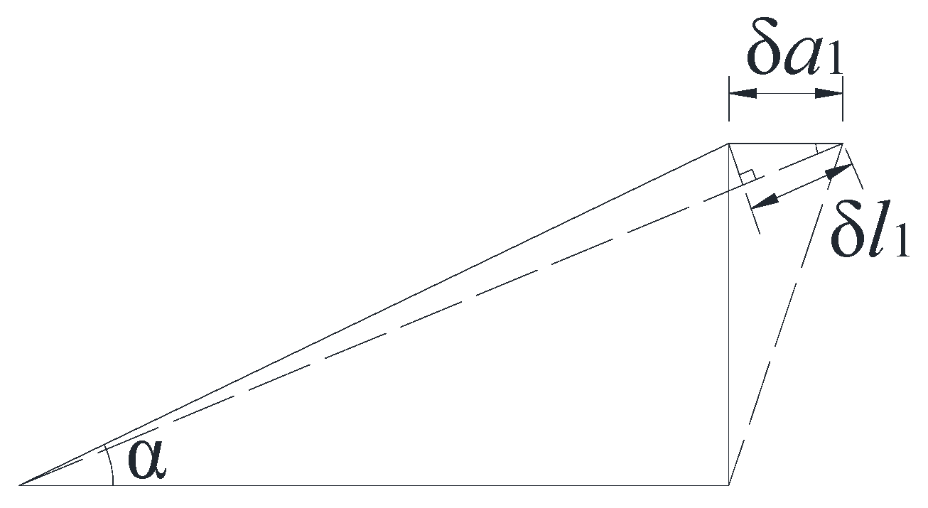
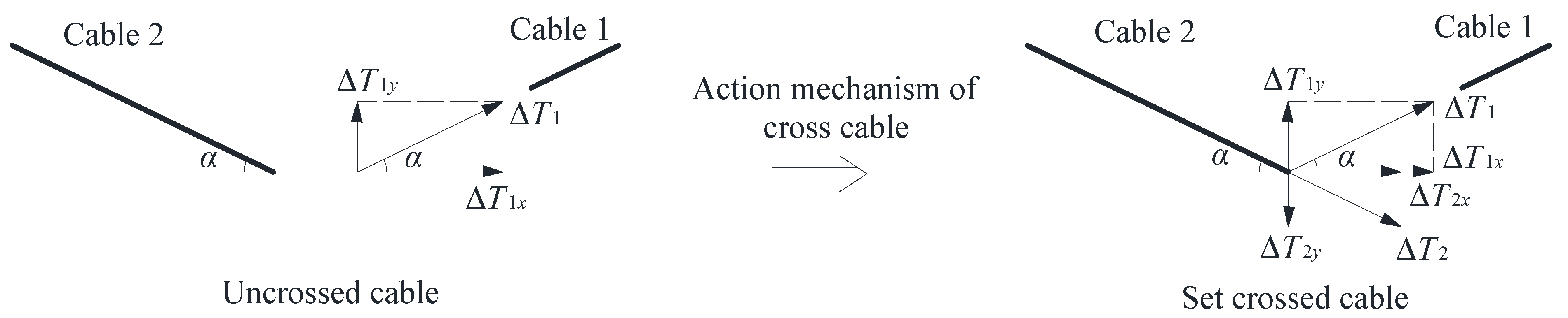
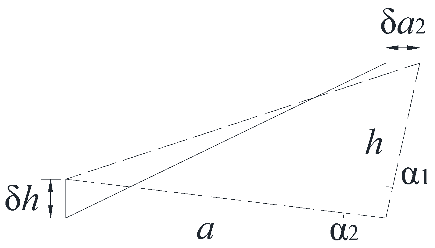
- When the horizontal external force acts on the middle tower, it can be divided into and parts. makes the deformation of the middle tower under the action of its own stiffness. makes the cable 1 elongate. The horizontal displacement amount of cable 1 near the end of the tower consists of two parts. One part is caused by the self-elongation of cable 1, and the other part is the horizontal displacement of cable 1 near the end of the middle tower due to the vertical deformation of the main beam. Taking the top of the middle tower as the research object, according to the principle of deformation coordination, the displacement of the middle tower under the action of should be equal to the displacement of cable 1 near the end of the tower under the action of . The horizontal deformation values of both are .
- (2)
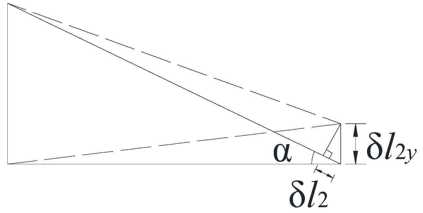
- The influence of the change in cable 1 cable force can be divided into two parts. One part causes the vertical deformation of the beam, and the other part compresses the length of the cable 2. According to the previous assumption, the displacement of the top of the side tower is ignored. Taking the main beam in the middle of the span as the research object, according to the principle of deformation coordination, the vertical displacement of the beam is equal to the vertical deformation of cable 2 near the end of the beam. The vertical deformation values of both are .
3. Results and Discussion
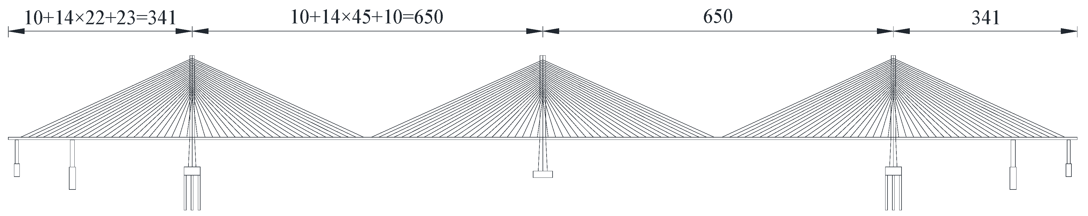
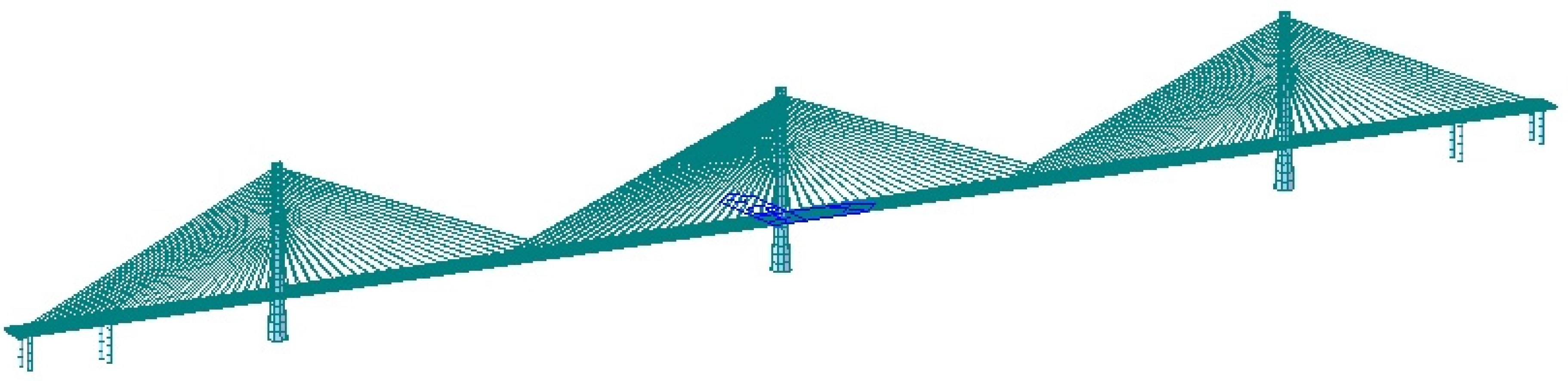
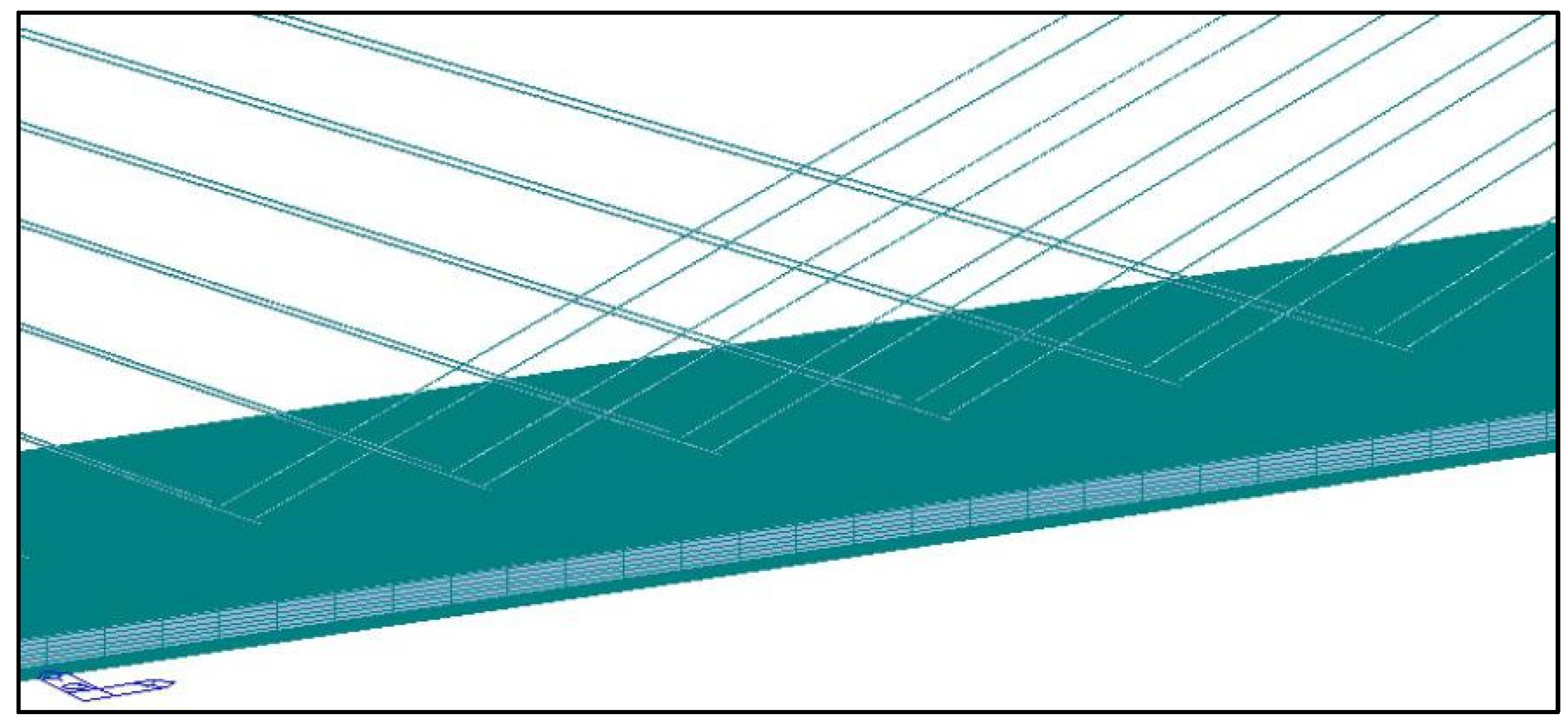
3.1. Structural Parameters
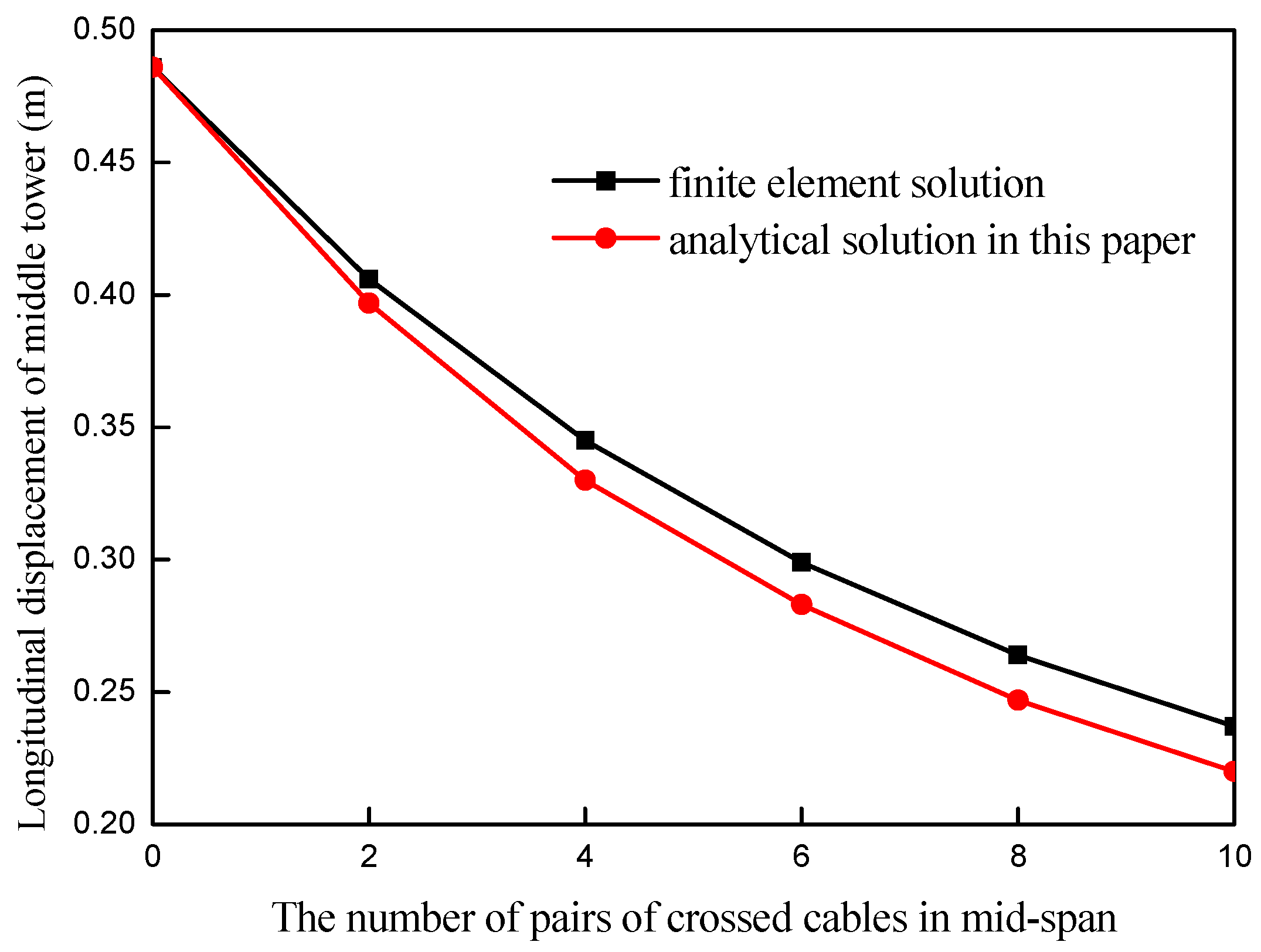
3.2. Verification of Analytical Solution
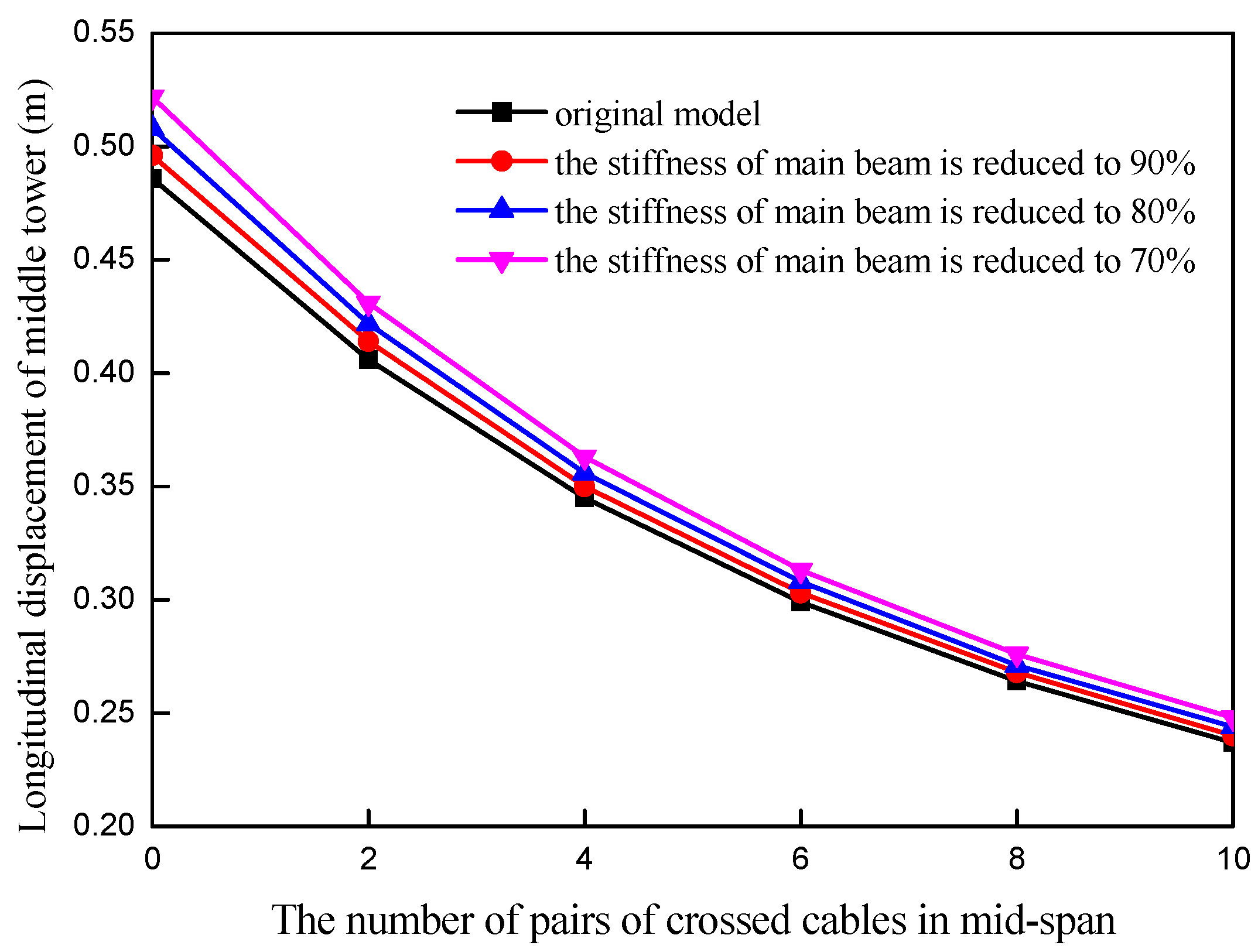
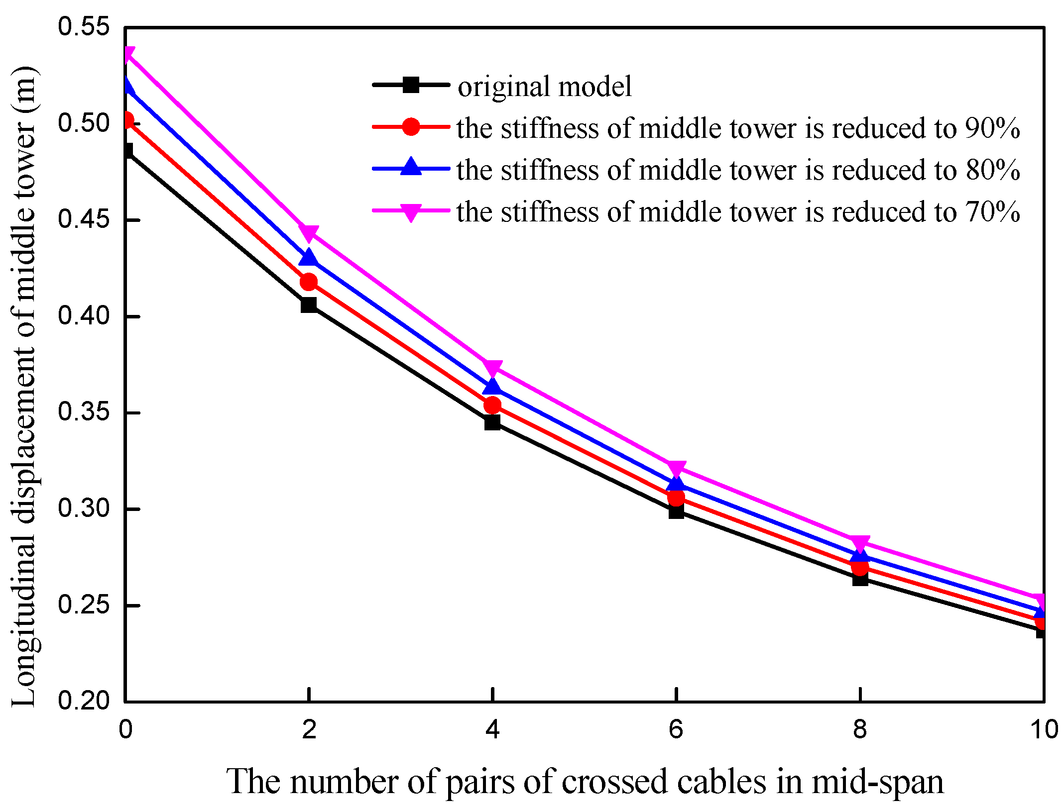
3.3. Analysis of the Influence of Tower and Main Beam on the Stiffness of Middle Tower
4. Conclusions and Recommendations
- (1)
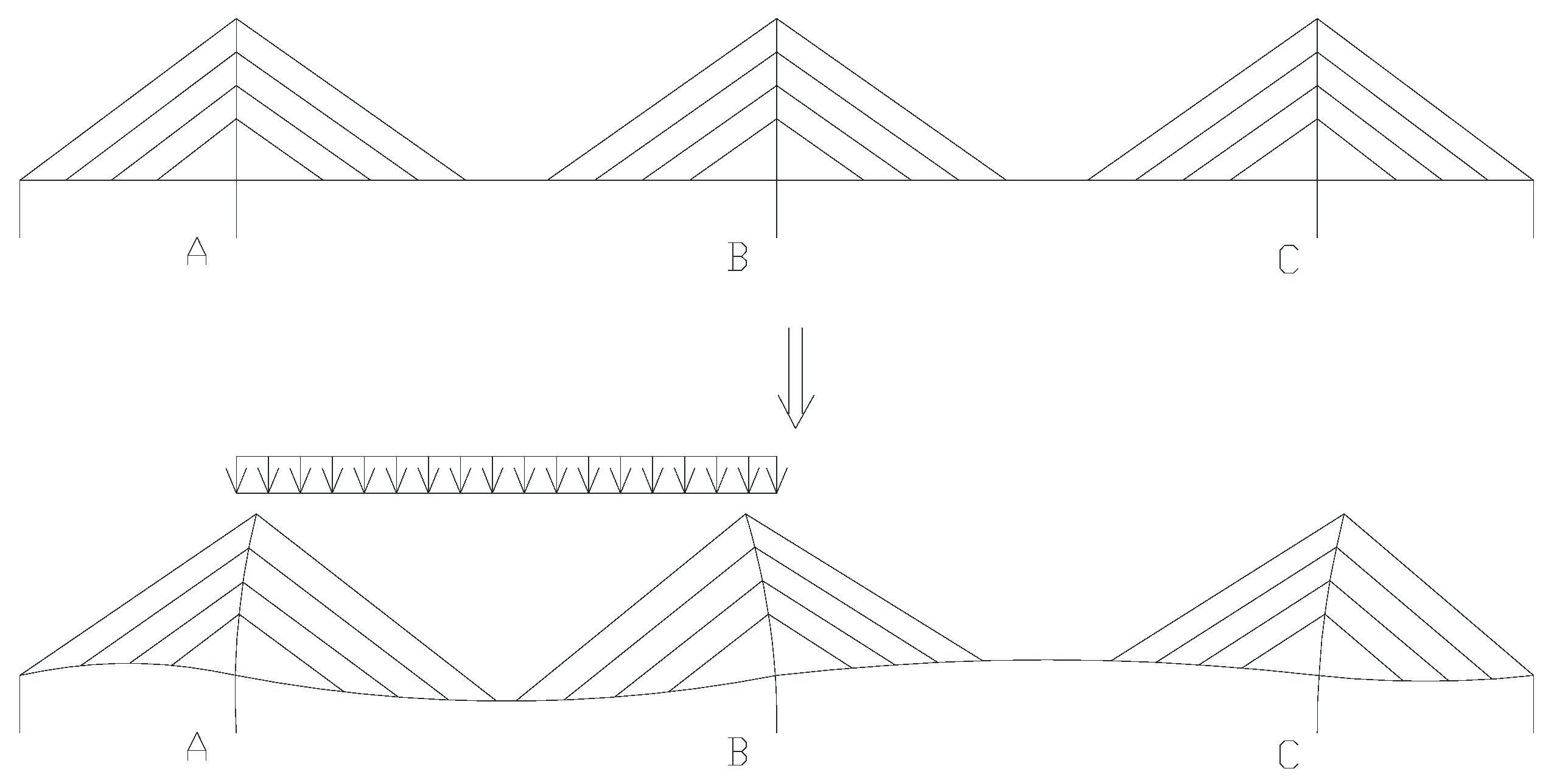
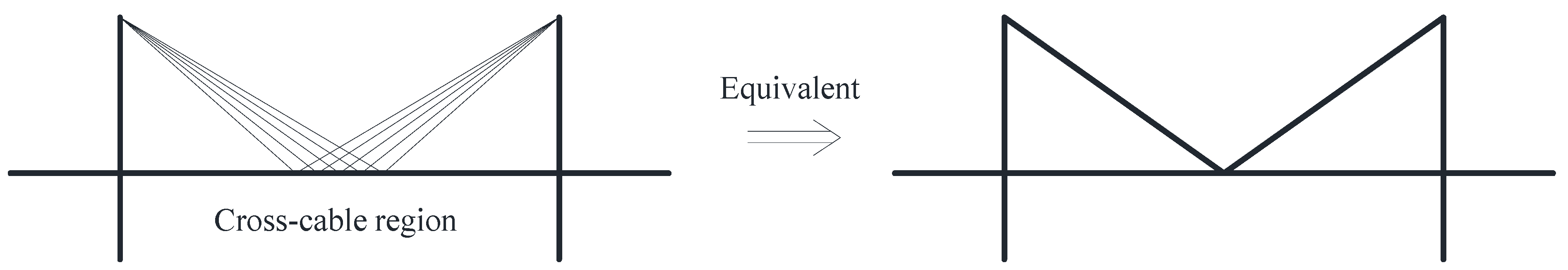
- In this paper, the action mechanism of the cross cable is revealed as a result of mechanical analysis. That is, the cross cable in the middle of the span can weaken the vertical force that causes the deformation of the main beam and then reduce the overall deformation of the structure and improve the overall stiffness of the structure.
- (2)
- Using the deformation coordination principle twice, we derive the analytical solution for calculating the longitudinal anti-push stiffness of the middle tower of cross-cable multi-tower cable-stayed bridges. The formula shows that the influence of the cross cable on the stiffness of the middle tower is related to its stiffness, the stiffness of the main beam, the main span, the height of the tower, and the length of the cross cable.
- (3)
- The accuracy of the analytical solution is verified by an example of the finite element model. The analysis shows that the error of the analytical formula is less than 2–8%, which meets the accuracy requirements of the scheme design stage of the multi-tower cable-stayed bridge. The analytical formula can quickly determine the number of cross cables in the mid-span, with the stiffness of the middle tower being the target value. It can provide guidance and a reference for scheme designs which aim to improve the structural stiffness of multi-tower cable-stayed bridges by setting cross cables.
- (4)
- The stiffness of the beam and tower itself has a certain influence on the overall stiffness of the structure, and the influence of the tower stiffness is greater than that of the beam. However, compared with setting the cross cables, the method of improving the structural stiffness by increasing the stiffness of the tower or the beam is inefficient and uneconomical.
Author Contributions
Funding
Data Availability Statement
Conflicts of Interest
References
- Kite, S.E.; Hornby, R.; Minto, B.; Carter, M.T.; Hussain, N.M. Queensferry Crossing, Scotland-scheme, specimen and definition designs. J. Bridge Eng. 2019, 172, 92–112. [Google Scholar]
- Yang, X.Y.; Xia, T. The design of FRC in Scotland. Bridge 2011, 2, 5–7. [Google Scholar]
- Kite, S.E.; Hussain, N.M.; Carter, M.T. Forth replacement crossing-Scotland, UK. Procedia Eng. 2011, 14, 1480–1484. [Google Scholar] [CrossRef]
- Carter, M.T.; Kite, S.E.; Hussainm, N.M.; Minto, B. Design of the Forth replacement crossing, Scotland. Proc. Inst. Civ. Eng. 2010, 163, 91–99. [Google Scholar] [CrossRef]
- Ning, B.W. Overall design of Bianyuzhou Yangtze river bridge on newly-built Anjiu high-speed railway. Bridge Constr. 2020, 50, 86–91. [Google Scholar]
- Wang, P.H.; Yang, C.G. Parametric studies on cable-stayed bridges. Comput. Struct. 1996, 60, 243–260. [Google Scholar] [CrossRef]
- Gimsing, N.J. Cable Supported Bridges: Concept & Design; John Wiley & Sons, Ltd. Publication: Hoboken, NJ, USA, 1997. [Google Scholar]
- Yu, B.C.; Wang, J.S.; Ai, J.; Sun, R.Y. The structural form and development of cable-stayed bridge. In Proceedings of the 2017 2nd International Conference on Advances in Materials, Mechatronics and Civil Engineering (ICAMMCE 2017), Guangzhou, China, 19–20 January 2017; Volume 121, pp. 61–64. [Google Scholar]
- Dong, H.C.; Sun, G.G.; Hoon, Y.; Ho, S.N. Nonlinear static analysis of continuous multi-span suspension bridges. Int. J. Steel Struct. 2013, 13, 103–115. [Google Scholar]
- Huu, T.T.; Dong, H.C. Advanced analysis of multi-span suspension bridges. J. Constr. Steel Res. 2013, 90, 29–41. [Google Scholar]
- Pei, B.D.; Chong, A.X.; Xia, H.; Kang, X.Y. Design and key construction technology of steel-concrete-steel sandwich composite pylon for a large span cable-stayed bridge. Sci. Rep. 2023, 13, 6626. [Google Scholar] [CrossRef] [PubMed]
- Nagal, M.; Fujino, Y.; Yamaguchi, H. Feasibility of a 1400 m span steel cable-stayed bridge. J. Bridge Eng. 2004, 9, 444–452. [Google Scholar]
- Shi, X.F.; Sun, J.Y. Static performance analysis of three-tower cable-stayed bridge. Acad. Symp. Bridge Struct. Eng. 2001, 10, 470–477. [Google Scholar]
- Gimsing, N.J. The modern cable-stayed bridge—50 years of development from 1955 to 2005. In Proceedings of the International Symposium on Innovation & Sustainability of Structures in Civil Engineering, Nanjing, China, 1 January 2005; Volume 1, pp. 47–64. [Google Scholar]
- Chai, S.B.; Wang, X.L. Simplified calculation method for deformation of multi-tower cable-stayed bridges with crossed cables. Eng. Struct. 2019, 181, 354–361. [Google Scholar] [CrossRef]
- Cid, C.; Baldomir, A.; Hernandez, S. Optimum crossing cable system in multi-span cable-stayed bridges. Eng. Struct. 2018, 160, 342–355. [Google Scholar] [CrossRef]
- Xia, G.P.; Zhang, Z. Cable deflection and gravity stiffness of cable-stayed suspension bridge. Adv. Mater. Res. 2011, 255, 1039–1042. [Google Scholar] [CrossRef]
- Alsayed, M.; Lin, L.; Hassan, J. Static behavior of partially earth-anchored cable-stayed bridge of different side-to-main span ratios: Super-long span system with crossing cables. Structures 2021, 33, 3736–3745. [Google Scholar] [CrossRef]
- Arellano, H.; Tolentino, D.; Gomez, R. Optimum criss crossing cables in multi-span cable-stayed bridges using genetic algorithms. J. Civ. Eng. 2019, 23, 719–728. [Google Scholar] [CrossRef]
- Tang, M.C. Cable-stayed bridges. In Bridge Engineering Handbook; Chen, W.F., Duan, L., Eds.; CRC Press: Boca Raton, FL, USA, 2000. [Google Scholar]
- Zhou, N.X. Prospect of design conception of cable-stayed bridge in the 21st century. In Proceedings of the 13th National Bridge Academic Conference, Shanghai, China, 16–19 November 1998; pp. 161–170. [Google Scholar]
- Chen, A.R.; Xiang, H.F. Conceptual design of multi-tower cable-stayed bridge. In Proceedings of the 13th National Bridge Academic Conference, Shanghai, China, 16–19 November 1998; pp. 171–177. [Google Scholar]
- Chai, S.B.; Xiao, R.C.; Wang, X.L. Longitudinal restraint stiffness of cross cables of multi-tower cable-stayed bridges. J. Harbin Inst. Technol. 2016, 48, 119–124. [Google Scholar]
- Zhou, L.J. Test Study on Vertical Stiffness of Railway Vable-Stayed Bridge with Three Towers and Double Main Span. Ph.D. Thesis, Central South University, Changsha, China, 2013. [Google Scholar]
- Zhang, Y.Y. Approximate Calculation and Study of Structural System in Cable-Stayed Bridge. Ph.D. Thesis, Tongji University, Shanghai, China, 2010. [Google Scholar]
- Li, Z.S.; Lei, J.Q. Solution and analysis of cable support stiffness coefficient of multi-tower cable-stayed bridge. J. Chang. Univ. (Nat. Sci. Ed.) 2015, 35, 83–90. [Google Scholar]
- Xiong, F.; Chen, C.C. A comparative study on the economic characteristics of the extradosed cable-stayed bridge and cable stayed bridge. Appl. Mech. Mater. 2015, 721, 744–746. [Google Scholar] [CrossRef]
- Yao, S.S.; Peng, B.; Wang, L.Y.; Chen, H.D. Structural performance and reasonable cross-ratio of cross-cable multi-tower cable-stayed bridges. Buildings 2022, 12, 764. [Google Scholar] [CrossRef]


| (kN) | Horizontal Displacement of the Top of the Middle Tower (m) | Horizontal Displacement of the Top of the Side Tower (m) | Stiffness of the Middle Tower (kN·m−1) |
|---|---|---|---|
| 20,000 | 0.486 | −0.003 | 41,165.8 |
| The Number of Pairs of Crossed Cables in Mid-Span | Horizontal Displacement of the Top of the Middle Tower (m) | Horizontal Displacement of the Top of the Side Tower (m) | Ratio of Horizontal Displacement at the Top of the Middle Tower to the Side Tower (%) | Stiffness of the Middle Tower (kN·m−1) |
|---|---|---|---|---|
| 2 | 0.406 | −0.011 | 2.71 | 49,261.1 |
| 4 | 0.345 | −0.013 | 3.77 | 57,971.0 |
| 6 | 0.299 | −0.015 | 5.02 | 66,889.6 |
| 8 | 0.264 | −0.017 | 6.44 | 75,757.6 |
| 10 | 0.237 | −0.022 | 9.28 | 84,388.2 |
| The Number of Pairs of Crossed Cables in Mid-Span | Stiffness of the Middle Tower (kN·m−1) | Error of Analytical Solution * (%) | |
|---|---|---|---|
| The Analytical Solution in This Paper | The Calculation Solution of Finite Element Model | ||
| 2 | 50,349.3 | 49,261.1 | 2.21 |
| 4 | 60,545.7 | 57,971.0 | 4.44 |
| 6 | 70,738.7 | 66,889.6 | 5.75 |
| 8 | 80,930.9 | 75,757.6 | 6.83 |
| 10 | 91,122.6 | 84,388.2 | 7.98 |
Disclaimer/Publisher’s Note: The statements, opinions and data contained in all publications are solely those of the individual author(s) and contributor(s) and not of MDPI and/or the editor(s). MDPI and/or the editor(s) disclaim responsibility for any injury to people or property resulting from any ideas, methods, instructions or products referred to in the content. |
© 2023 by the authors. Licensee MDPI, Basel, Switzerland. This article is an open access article distributed under the terms and conditions of the Creative Commons Attribution (CC BY) license (https://creativecommons.org/licenses/by/4.0/).
Share and Cite
Yao, S.; Wang, L.; Peng, B.; Chen, H. Analytical Solution for Longitudinal Anti-Push Stiffness of the Middle Tower of Cross-Cable Multi-Tower Cable-Stayed Bridge. Buildings 2023, 13, 2158. https://doi.org/10.3390/buildings13092158
Yao S, Wang L, Peng B, Chen H. Analytical Solution for Longitudinal Anti-Push Stiffness of the Middle Tower of Cross-Cable Multi-Tower Cable-Stayed Bridge. Buildings. 2023; 13(9):2158. https://doi.org/10.3390/buildings13092158
Chicago/Turabian StyleYao, Sisi, Luyao Wang, Biao Peng, and Hengda Chen. 2023. "Analytical Solution for Longitudinal Anti-Push Stiffness of the Middle Tower of Cross-Cable Multi-Tower Cable-Stayed Bridge" Buildings 13, no. 9: 2158. https://doi.org/10.3390/buildings13092158