Article

Comparing Mechanical Characterization of Carbon, Kevlar, and Hybrid-Fiber-Reinforced Concrete under Quasistatic and Dynamic Loadings

1
Department of Civil Engineering, National Taipei University of Technology, Taipei 10608, Taiwan
2
Department of Materials, National Taipei University of Technology, Taipei 10608, Taiwan
3
Department of Aerospace and Systems Engineering, Feng Chia University, Taichung 40724, Taiwan
4
Department of Environmental Information and Engineering, Chung Cheng Institute of Technology, National Defense University, Taoyuan 33551, Taiwan
*
Author to whom correspondence should be addressed.
Buildings 2023, 13(8), 2044; https://doi.org/10.3390/buildings13082044
Submission received: 24 July 2023 / Revised: 7 August 2023 / Accepted: 9 August 2023 / Published: 10 August 2023
(This article belongs to the Special Issue Advances in Cement Composite Materials)

Abstract

:
Concrete is a brittle material due to its poor tensile strength; consequently, concrete tends to crack or peel under an applied external load. Previous studies have investigated the effect of incorporating fiber into concrete, which can improve its tensile strength. In this study, the static and dynamic mechanical characteristics of three types of fiber-reinforced concrete (FRC) were examined: carbon-fiber-reinforced concrete (CFRC); Kevlar-fiber-reinforced concrete (KFRC); and a combination of both, known as carbon/Kevlar-hybrid-fiber-reinforced concrete (HFRC). This study created concrete specimens by pneumatically dispersing carbon and Kevlar fibers and mixing them with cement to comprise 1% of the weight. The mixture was then combined with aggregates and water to form the concrete specimens. When compared with the benchmark concrete specimens, it was found that the compressive strength of the CFRC, KFRC, and HFRC specimens increased by about 19% to 50%, the bending strength increase by about 8% to 32%, and the splitting strength increased by about 4% to 36%. Specifically, the HFRC made with the 24 mm carbon and Kevlar fibers displayed the most significant mechanical strength in a static state. Furthermore, the HFRC showed superior resistance to impact compared to the benchmark concrete specimens across various impact energies, with the 24 mm carbon and Kevlar fiber HFRC showing the highest resistance. The inclusion of fibers in the split Hopkinson pressure bar (SHPB) test demonstrated a notable increase in the maximum strength, particularly in the case of the 12 mm carbon fiber combined with the 24 mm Kevlar fiber in the HFRC specimen.

1. Introduction

Concrete is prone to damage due to its inherent brittleness and low tensile strength, particularly when subjected to overloading or repeated dynamic forces. In an effort to overcome these shortcomings, fiber-reinforced concrete (FRC) has been engineered. This composite material is developed by integrating fibrous elements into the concrete. FRC offers several advantages, including an improved impact strength, crack limitation, enhanced durability, resistance to freeze–thaw cycles, mitigation of plastic shrinkage, increased toughness, and enhanced fatigue strength. Consequently, FRC finds applications in scenarios where high tensile strength, reduced cracking, or conventional reinforcement placement is impractical. Examples of applications for this material include use in concrete pavements, airplane runways, spillways of dams, the expansion joints of highway bridges, and tunnel constructions.
The mechanical attributes and ease of use of FRC can be adjusted by a number of variables, such as the kind of fiber used, the ratio of fiber to cement, and the length of the fibers. To enhance the mechanical performance of concrete, fibers such as chopped carbon, steel, aramid, glass, polyvinyl alcohol (PVA), and polyethylene are frequently used. Both single-typed fiber-reinforced concrete and hybrid-fiber-reinforced concrete (HFRC) are frequently used to improve concrete’s mechanical properties [1,2,3]. Table 1 provides an overview of the material properties of popular fiber types [4,5,6,7,8].
Prior research has indicated that the fiber-to-cement ratio significantly influences the mechanical characteristics of fiber-reinforced concrete [9,10,11,12,13,14,15]. For example, steel-fiber-reinforced concrete demonstrates maximum tensile strength when cured for 28 days at a volume percentage of 1.5% [16]. Conversely, an increase in the glass fiber weight percentage beyond 0.1% results in a decline in the compressive strength of the fiber-reinforced concrete [17]. Research conducted on basalt-fiber-reinforced concrete (BFRC) has evaluated the effects of varying the basalt-fiber-to-cement ratios on its mechanical strength. BFRC shows an optimal strength increment at a weight percentage of 0.2%; any further increase in the fiber content causes a decline in the strength increment [18,19,20,21,22,23]. Studies on cement and concrete’s mechanical attributes and microstructures have been performed by utilizing different carbon fibers, fiber lengths, and fiber ratios [24,25,26,27,28,29,30].
The length of fibers notably affects FRC’s mechanical properties. Bijo and Unnikrishnan found that hybrid FRC incorporating 12 mm polypropylene fiber and 50 mm coconut fiber at a 0.2% volume displayed maximum impact resistance [31]. Yoo and colleagues tested ultrahigh-performance fiber-reinforced concrete (UHPFRC) with steel fibers of different lengths (16 mm, 17.5 mm, and 19.5 mm) and found that the 19.5 mm steel fiber yielded the greatest flexural strength [32]. Mastali et al. [33] utilized recycled carbon fiber of various lengths from a carbon-fiber-reinforced polymer (CFRP), concluding that CFRC with 30 mm of recycled carbon fiber showed superior compressive and flexural strength. Additionally, Li et al. [34] found that 6 mm basalt fiber displayed an enhanced compressive strength, while 24 mm basalt fiber showed a greater splitting tensile and flexural strength.
Carbon fiber, known for its high density, strength, light weight, chemical and high-temperature resistance, and low thermal expansion, is widely used in aerospace engineering, racing, military, and sports products. When added to concrete, it hinders the crack propagation, thereby improving FRC’s mechanical properties [35,36,37]. Conversely, Kevlar fiber, a strong and lightweight organic fiber with a tensile strength five times that of steel and a density about one fifth of steel [38], improves FRC’s mechanical properties and impact resistance when incorporated [39,40].
Hybrid-fiber-reinforced concrete (HFRC), a blend of at least two fiber types, boosts FRC’s mechanical properties through fiber synergy [41,42]. Steel–polypropylene HFRC, for example, shows excellent synergistic behavior, particularly at lower hybrid-fiber-to-cement-volume fractions [43]. The introduction of polypropylene and basalt fibers to concrete enhances its acid–alkali and crack propagation resistance [44]. Studies on hybrid-fiber-reinforced concrete (HFRC) with Kevlar and carbon fibers revealed that a 1% fiber-to-cement-weight percentage maximizes the mechanical strength [45].
While FRC improves the static mechanical performance and dynamic loading resistance compared to regular concrete, a high static strength does not always correspond to a high impact resistance as the fiber type plays a crucial role [46,47]. The Hopkinson pressure bar, proposed by Hopkinson in 1914 [48] and later refined by Kolsky in 1949 [49], is often used to measure high strain rates [50,51,52]. Previous studies [53,54,55] have played a vital role in advancing the study of the mechanical behavior of rocks and concrete subjected to dynamic loading and high strain rates. However, the standard split Hopkinson pressure bar (SHPB) test configuration does not suit studies on high strain rates’ effect on soft materials due to repeated loading pulse issues. Nemat-Nasser et al. [56] devised a momentum trapping method for a single stress pulse, involving an incident tube and a reaction mass for a tensile pulse after the compression pulse. Later research has successfully applied similar concepts [57,58,59]. The dynamic stress–strain relationship of the cementitious material from the SHPB test can contribute to further studies on explosive-induced air-blast loadings [60].
This study focuses on carbon and aramid fibers, which exhibit a higher tensile strength and elastic modulus than other fibers. The goal is to explore the static and dynamic mechanical properties of carbon-fiber-reinforced concrete (CFRC), Kevlar-fiber-reinforced concrete (KFRC) with varying length ratios, and carbon/Kevlar-hybrid-fiber-reinforced concrete (HFRC).

2. Materials

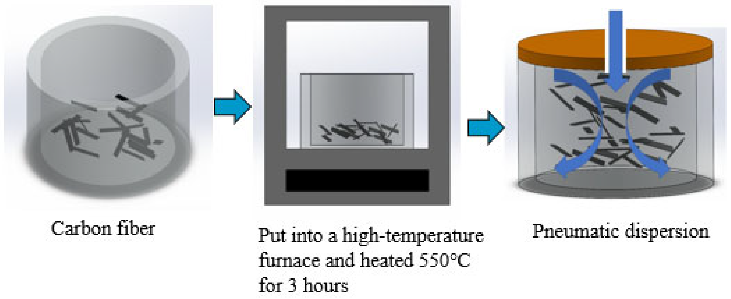
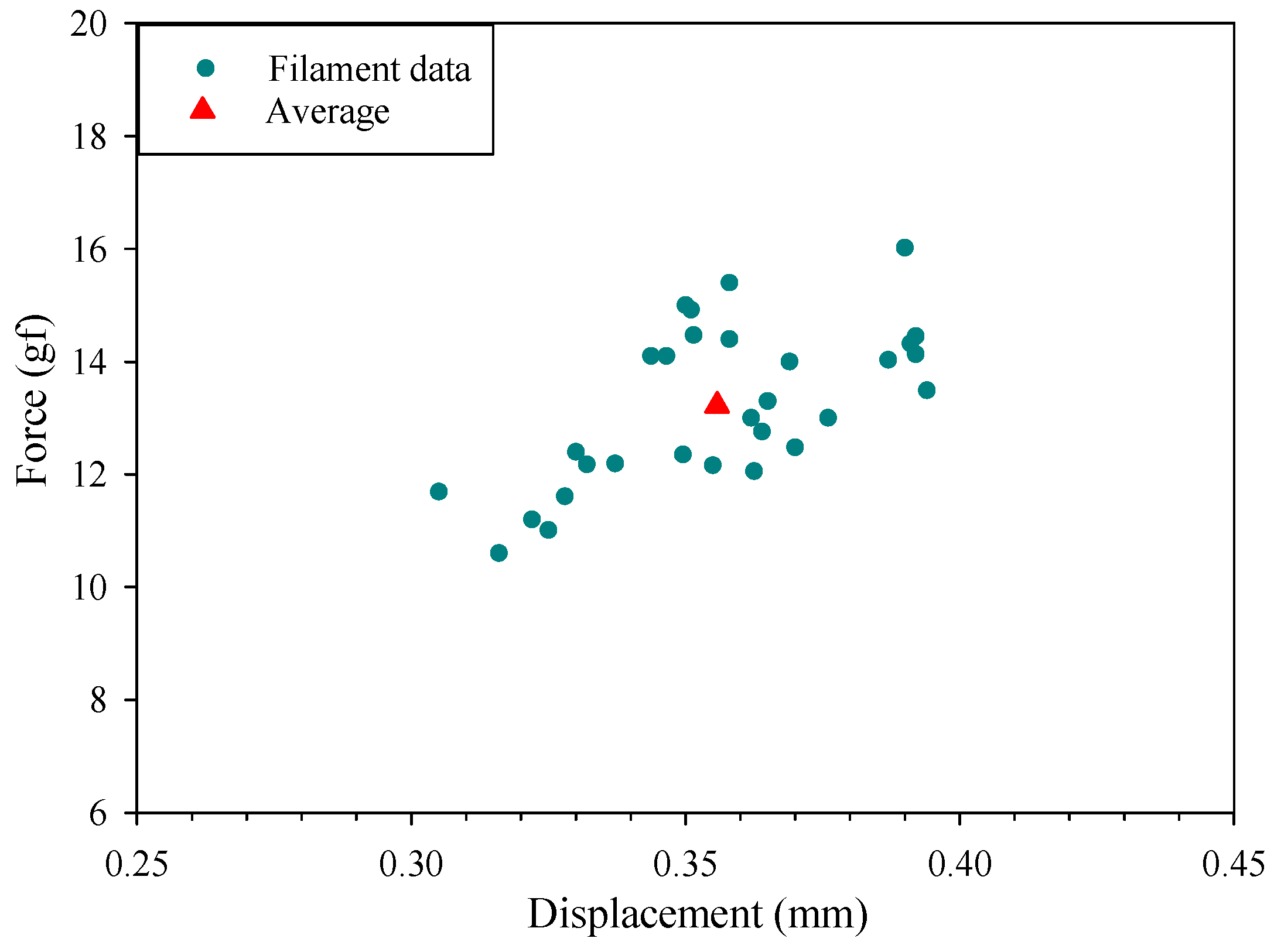
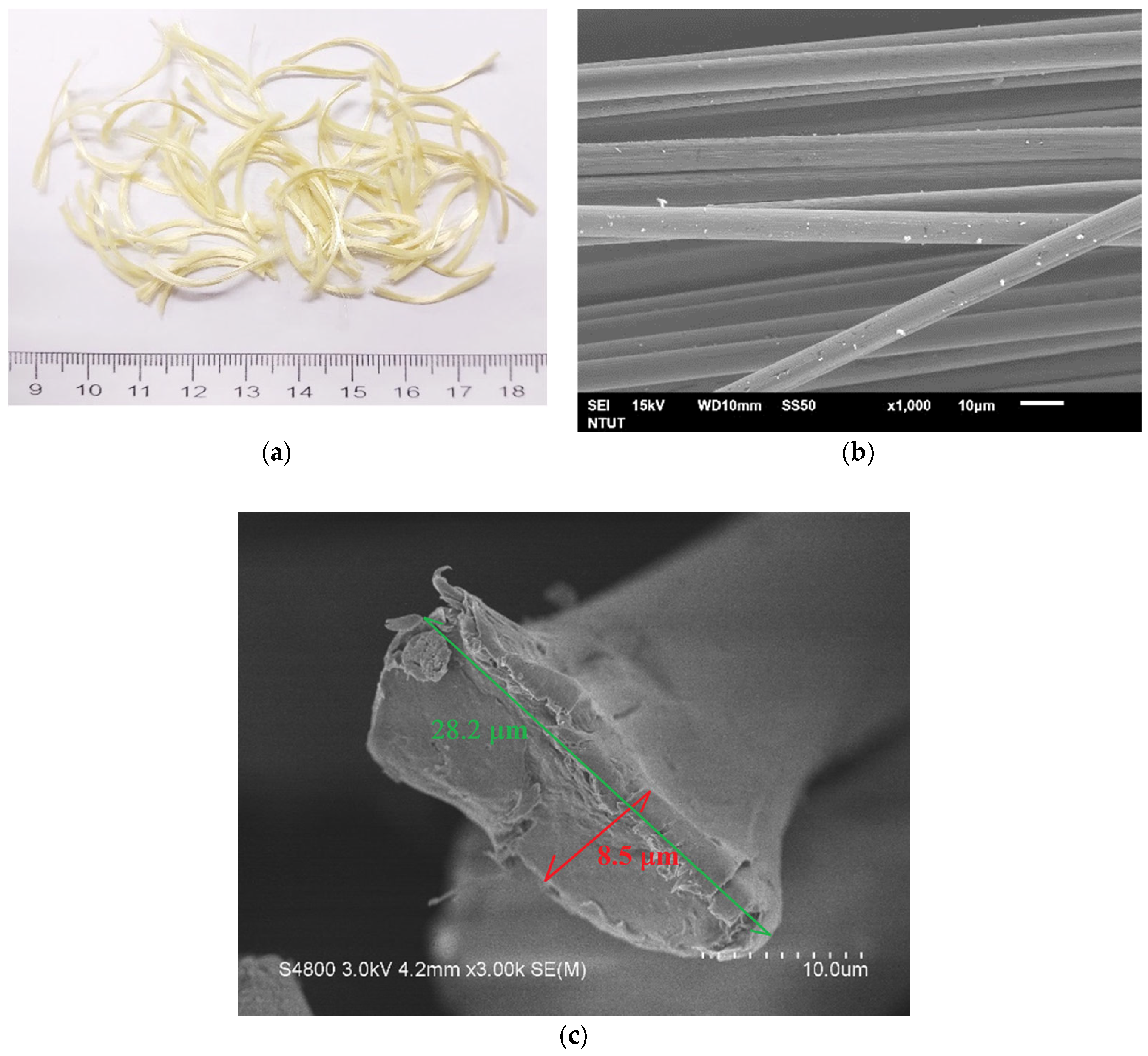
2.1. Carbon Fiber (CF)

Carbon fiber (CF) (TC36P, Tairyfil, Formosa Plastics Corporation, Taipei, Taiwan) was employed to produce the CFRC and HFRC specimens. The CF exhibited tensile strength, tensile modulus, and elongation properties of 4900 MPa, 250 GPa, and 2.0%, respectively. Furthermore, potential interference with the mechanical attributes of FRC was anticipated from the sizing present on the CF surface [61,62].
To mitigate this interference, the CF was placed in a crucible and subjected to a temperature of 550 °C for a duration of 3 h to remove the sizing [63]. Upon completion of this process, the CF was dispersed by utilizing a pneumatic dispersion method, as illustrated in Figure 1.
In the present study, a scanning electron microscope (SEM, JEOL, JSM-6510LV, Tokyo, Japan) was utilized to examine the fiber surface imagery. Figure 2a depicts the cross-sectional view of the original carbon fiber, having a diameter of 8.0 μm. Meanwhile, Figure 2b,c provide SEM images of the original chopped CF and the sizing-removed chopped CF, respectively, both captured at a 1000-fold magnification.
The single filament tensile strength of the original carbon fiber was conducted per ASTM D3822-07 [64]. The single filament tensile test results of the original carbon fiber showed that the average tensile force was 13.22 ± 1.39 gf and the average fracture displacement was 0.356 ± 0.024 mm. Figure 3 illustrates the failure force and displacement for the original carbon fiber filaments.

2.2. Kevlar Fiber (KF)

DuPont’s Kevlar® 29 fiber was used in this study to improve the strength of the concrete. The chemical formula of Kevlar is –[-CO-C6H4-CONH-C6H4-NH-]-. KF is thermally stable and chemically resistant, especially in acetic acid, hydrochloric acid, and other acidic chemicals. The tensile strength, tensile modulus, and elongation of KF were measured at 2920 Mpa, 70 Gpa, and 3.6%, respectively; two lengths of KF, namely 12 mm and 24 mm, were used.
Figure 4a,b present images of the chopped KF and its corresponding SEM representation at a 1000-fold magnification, respectively. Figure 4c illustrates the SEM-acquired cross-sectional view of the Kevlar fiber. The KF was dispersed in a manner similar to the CF, utilizing the pneumatic dispersion method.
The single filament tensile strength of the Kevlar fiber was also conducted per ASTM D3822-07 [64]. The single filament tensile test results of the Kevlar fiber showed that the average tensile force was 51.27 ± 8.54 gf and the average fracture displacement was 0.660 ± 0.087 mm. Figure 5 illustrates the failure force and displacement for the Kevlar fiber filaments.

2.3. Cement and Aggregate

The main binder used in this study was Type I Portland cement, supplied by Taiwan Cement Ltd (Taipei, Taiwan). The fineness modulus (F.M.) of both the fine and coarse aggregates was determined following the ASTM C33/C33M-18 standard [65]. The calculated F.M. values for the fine and coarse aggregates were 4.71 and 7.17, respectively. Furthermore, the overall F.M. value for all the aggregates combined was measured to be 5.96.

3. Experimental Methods

There were nine different specimens in this experiment, including the benchmark, CFRC, KFRC, and HFRC. The HFRC specimens were prepared in different proportions including two fiber types with two fiber lengths that were 1% of the weight percentage of the total fiber-to-cement ratio. The mechanical properties, including those explored with the slump test, compressive test, three-point bending test, splitting tensile test, and impact test, were tested in this study based on ACI and ASTM standards.

3.1. Specimen Nomenclature

The specimen-naming convention is structured as follows: The first letter designates the type of mechanical test, such as a compression test (C), flexural test (F), splitting test (S), and impact test (I). The second letter denotes the type of fiber used, where “C” represents the carbon fiber and “K” represents the Kevlar fiber. The subsequent number indicates the length of the fiber; for instance, “12” signifies a length of 12 mm. For example, C-C12 refers to the CFRC specimen with a 12 mm carbon fiber used in the compressive test, while S-C12K12 represents the HFRC specimen with both 12 mm carbon and 12 mm Kevlar fibers used in the splitting test.

3.2. Slump Test

The workability of the control, CFRC, KFRC, and HFRC samples was evaluated by using a slump test as per ASTM C143/C143M-20 [66] specifications, designed to gauge the flowability and consistency of the concrete.

3.3. Compressive Test

The compressive strength of the control, CFRC, KFRC, and HFRC was determined in adherence to the ASTM C39/C39M-01 [67] guidelines, utilizing a universal testing machine (HT-9501 Series, Hong-Ta, Taipei, Taiwan). Cylindrical specimens (ϕ 10 cm × 20 cm) were subjected to a steady load rate ranging between 900 and 1800 N/s.

3.4. Three-Point Bending Test

The universal testing machine was again used to determine the flexural strength of the control, KFRC, CFRC, and HFRC as per ASTM C293-02 [68]. The three-point bending test was conducted on a specimen with dimensions of 28 cm × 7 cm × 7 cm (length × width × height) at a loading rate of 20 kPa/s, as shown in Figure 6. The rupture modulus or flexural strength of the specimen was calculated by using the formula below:
R = 3 P L 2 b d 2
where R stands for the rupture modulus (flexural strength) in Mpa, P for the maximum load as per the testing machine in N, L for the span length in mm, b for the average specimen width at rupture in mm, and d for the average specimen thickness at rupture in mm.

3.5. Splitting Tensile Test
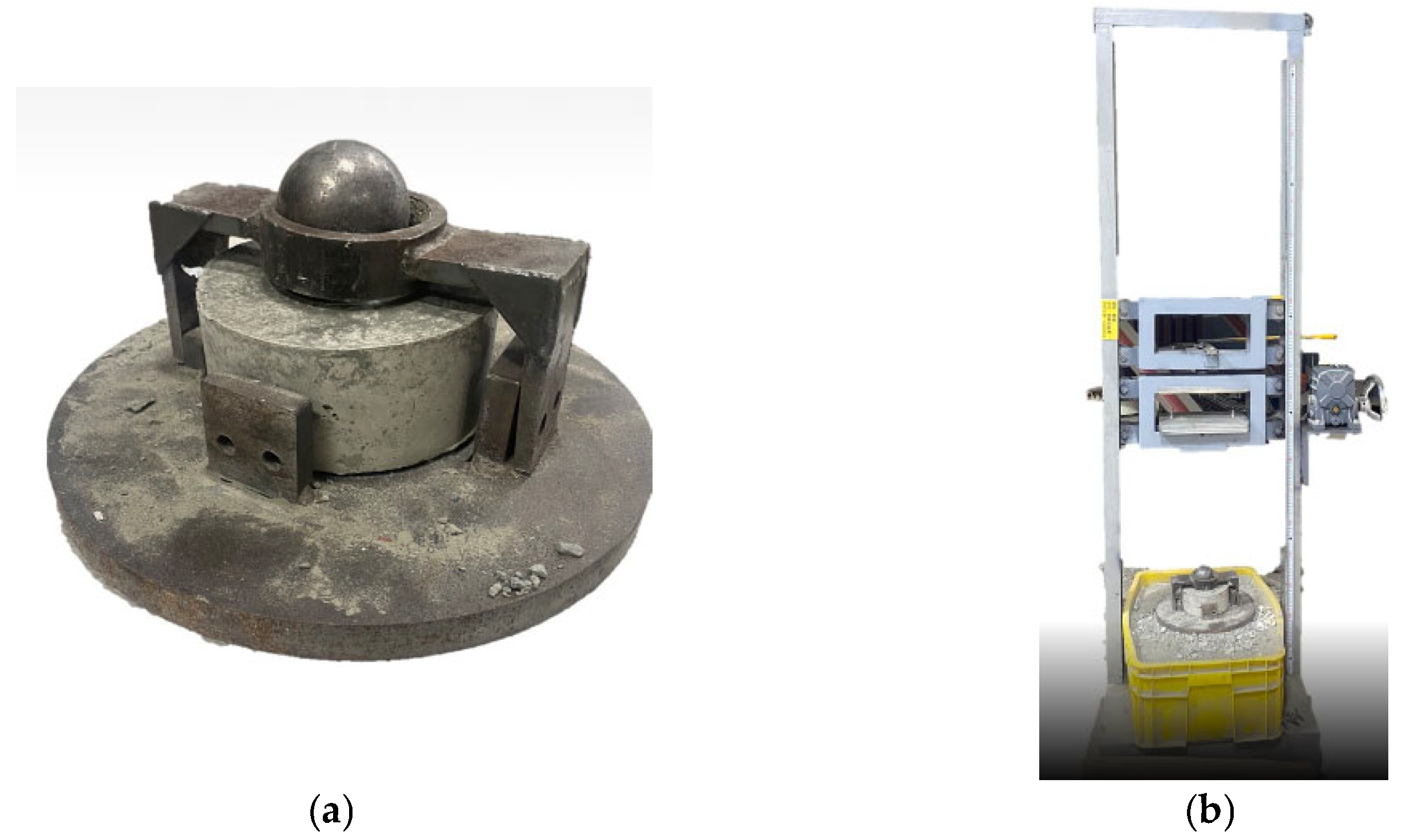
The universal testing machine was employed to conduct the splitting tensile strength test on the control, KFRC, CFRC, and HFRC samples in accordance with ASTM C496/C496M-17 [69]. The test was performed on a cylindrical specimen with dimensions ϕ 10 cm × 20 cm at a loading rate of 4300 N/min. The splitting tensile strength of the specimen was computed by using the following equation:
T = 2 P π L D
where T denotes the splitting tensile strength (Mpa), P stands for the maximum load applied as indicated by the testing machine (N), L stands for the length (mm), and d stands for the diameter (mm).

3.6. Impact Test

The impact test specimen, measuring ϕ 15.2 cm × 6.35 cm, was placed on a fixture with a hardened steel ball, as depicted in Figure 7a. The impact test was conducted following the guidelines of ACI 544.2R-89T [70] by using an impact testing machine (SP-006, Shengpeng, Yunlin, Taiwan). The specimen was positioned in a fixture and subsequently set on a sandbox’s top, as displayed in Figure 7b. The potential energy (E) can be computed as E = m × g × h, where m stands for the hammer’s mass (kg), g stands for the gravitational acceleration (m/s2), and h stands for the hammer’s setting height (m). The impact energies tested for both the control and HFRC specimens varied between 100 J and 300 J.

3.7. Split Hopkinson Pressure Bar Test

The device used in this study is located in the Materials Laboratory of the Environmental Information and Engineering Department of Chung Cheng Institute of Technology, National Defense University. The equipment was improved during the experiment, the original equipment was used in the experiment on the CFRC, and the HFRC was improved. Figure 8 illustrates the original SHPB devices.
During the SHPB examination, a striker bar was accelerated from the gas pressure chamber under a prescribed pressure, which impacted the incident bar and generated stress waves. These stress waves propagated from the incident bar to the specimen’s interface, leading to the creation of reflective and transmissive waves. Strain gauges were attached to the incident bar and transmission bar to record the strain–time signals of the incident wave ε i ( t ) , reflected wave ε r ( t ) , and transmitted wave ε t ( t ) . The specimen’s stress σ t , strain ε t , and strain rate ε ˙ (t) obtained from the three-wave method are represented as follows [71]:
ε t = C e L S 0 t [ ε i ( t ) ε r ( t ) ε t ( t ) ] t
ε ˙ t = C e L S [ ε i ( t ) ε r ( t ) ε t ( t ) ]
σ t = A e E 2 A S [ ε i t + ε r t + ε t ( t ) ]
where C e is the wave speed; E is the elastic modulus of the incident bar; A e is the cross-sectional area of the incident bar; and L s and A S are the length and cross-sectional area of the specimen, respectively.

4. Results and Discussion

This section outlines the findings from the experimental work conducted for this study. CF and KF, with sizing removed, were employed in the creation of the CFRC, KFRC, and HFRC specimens, which had varying fiber lengths and mixing proportions, and each maintained a 1% fiber-to-cement weight ratio. The specimens’ workability was evaluated via the slump test, while the ASTM and ACI standards were applied to ascertain the compressive strength, flexural strength, splitting tensile strength, and impact resistance.

4.1. Slump Test

Table 2 displays the slump values of the benchmark, CFRC, KFRC, and HFRC specimens at different weight percentages. Compared to the benchmark concrete, the CFRC, KFRC, and HFRC exhibited a significantly reduced workability, with slump values ranging from 20 mm to 30 mm, while the benchmark had a slump value of 78 mm.

4.2. Compression Test

Table 3 presents the compressive strengths of the C-C12, C-C24, C-K12, and C-K24 specimens. The average compressive strengths of these specimens were 30.01 MPa, 31.81 MPa, 27.73 MPa, and 31.49 MPa, respectively. Compared to the benchmark specimen, the average compressive strengths increased by 19.3%, 26.4%, 10.2%, and 25.2%, respectively.
The compressive strengths of the C-C12K12, C-C12K24, C-C24K12, and C-C24K24 specimens are presented in Table 4. The respective mean compressive strengths were measured to be 32.63 MPa, 33.63MPa, 35.32 MPa, and 37.86 MPa. In comparison to the benchmark specimen, these signify respective average compressive strength enhancements of 29.7%, 33.7%, 40.4%, and 50.5%.
Figure 9 illustrates the average compressive strengths of the benchmark, CFRC, KFRC, and HFRC specimens. The CFRC exhibited a higher compressive strength than the KFRC, and the length of the fiber had a positive correlation with the compression strength. The C-C24K24 specimen had the highest compressive strength among all the specimens.

4.3. Three-Point Bending Test

The flexural strengths of the F-C12, F-C24, F-K12, and F-K24 specimens are detailed in Table 5. They manifested average flexural strengths of 5.76 MPa, 5.91 MPa, 6.19 MPa, and 6.34 MPa, respectively. When compared to the benchmark specimen, these averages demonstrate enhancements in the flexural strength by 8.3%, 11.0%, 16.2%, and 19.0%, respectively.
Table 6 presents the flexural strengths of the F-C12K12, F-C12K24, F-C24K12, and F-C24K24 specimens. The average flexural strengths of these specimens were 6.41 MPa, 6.49 MPa, 6.89 MPa, and 7.02 MPa, respectively. Compared to the benchmark specimen, the average flexural strengths increased by 20.5%, 22.0%, 29.5%, and 32.0%, respectively.
Figure 10 portrays the mean flexural strengths of the benchmark, CFRC, KFRC, and HFRC specimens. It can be observed that the KFRC samples exhibited an enhanced flexural strength compared to the CFRC samples. Additionally, the fiber length displayed a beneficial association with the flexural strength. Remarkably, the F-C24K24 specimen stood out with the highest flexural strength among all the specimens.

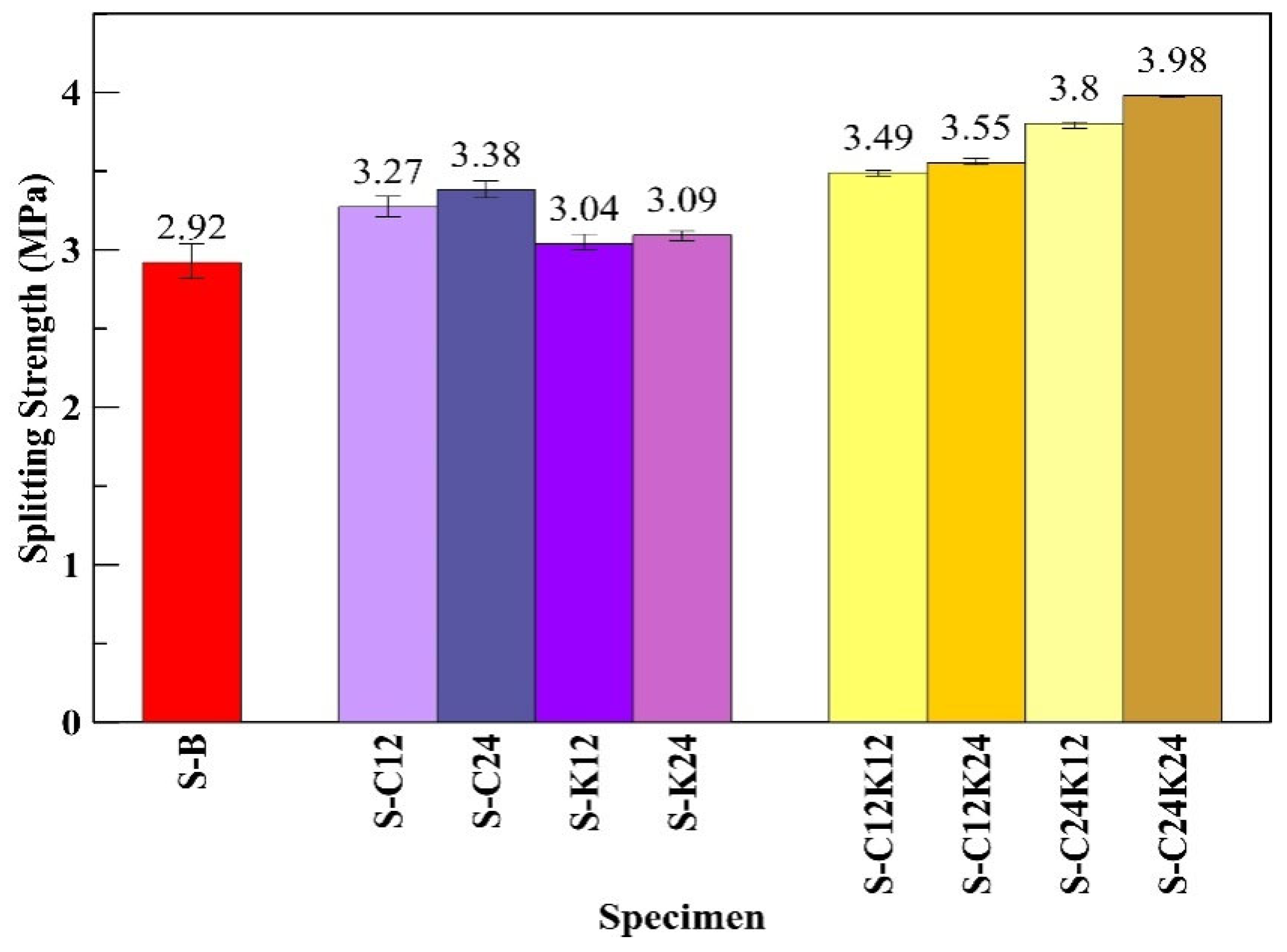
4.4. Splitting Tensile Test

Table 7 shows the splitting strengths of the S-C12, S-C24, S-K12, and S-K24 specimens. The average splitting strengths of these specimens were 3.27 MPa, 3.38 MPa, 3.04 MPa, and 3.09 MPa, respectively. Compared to the benchmark specimen, the average splitting strengths increased by 12.1%, 15.8%, 4.0%, and 5.9%, respectively.
Table 8 presents the splitting strengths of the S-C12K12, S-C12K24, S-C24K12, and S-C24K24 specimens. The average splitting strengths of these specimens were 3.49 MPa, 3.55 MPa, 3.80 MPa, and 3.99 MPa, respectively. Compared to the benchmark specimen, the average splitting strengths increased by 19.5%, 21.7%, 30.3%, and 36.5%, respectively.
Figure 11 presents the average splitting strengths of the benchmark, CFRC, KFRC, and HFRC specimens. As seen in Figure 11, it can be deduced that the CFRC exhibited a superior splitting strength compared to the KFRC, and a trend can be observed where an increase in the fiber length corresponds to a higher splitting strength. Notably, the S-C24K24 specimen had the highest peak splitting strength amongst all the samples.
According to the above quasistatic test results, the HFRC demonstrated highly improved mechanical performances compared with the CFRC and KFRC. Based on Table 1, the elongation of the carbon fiber ranged from 0.3 to 0.2% and of aramid ranged from 2.1 to 4.5%. When a force is applied to the FRC specimen, the concrete and the fibers would experience the same amount of strain, and since carbon fiber and Kevlar fiber have distinct elongation, it is suspected that the carbon fiber would break first while the Kevlar fiber would still maintain its overall structural integrity due to the synergistic effect of the two fibers [72].

4.5. Impact Test

Based on the previous test results, the HFRC exhibited greater strength compared to the single-type FRC. Therefore, the impact test was conducted on the HFRC and benchmark specimens by using impact energies of 100 J, 150 J, 200 J, 250 J, and 300 J. Table 9 presents the impact energies and corresponding impact numbers for the HFRC and benchmark specimens. For example, at 100 J of impact energy, the average impact numbers for the benchmark, I-12K12, I-C12K24, I-C24K12, and I-C24K24 HFRC specimens were 18.0, 37.5, 46.8, 56.5, and 79.0, respectively.
Figure 12 illustrates the average impact resistance of the benchmark and HFRC specimens. Specimen I-C24K24 exhibited the highest impact number under different impact energies. It was observed that the HFRC with longer fibers demonstrated greater impact resistance.

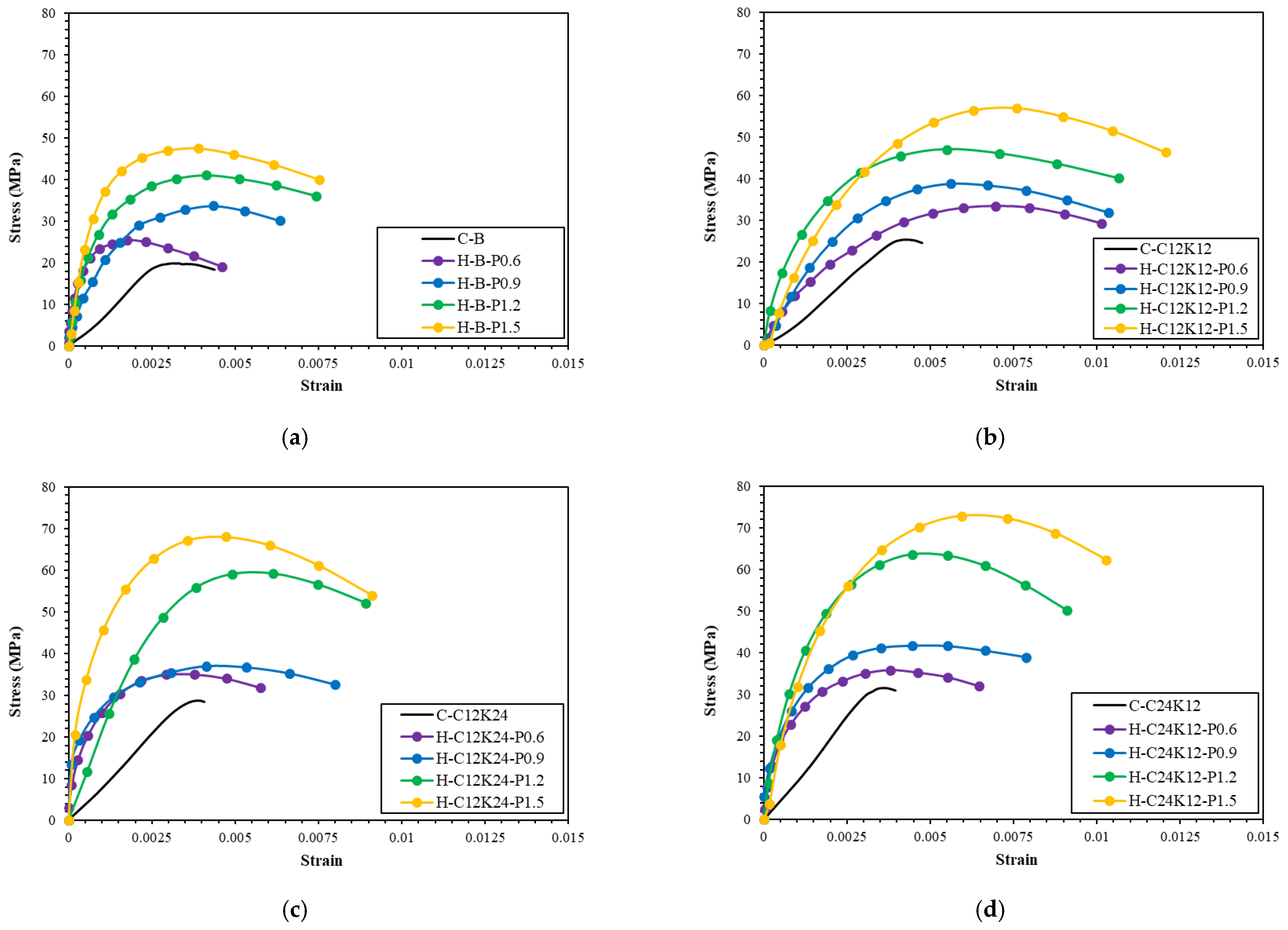
4.6. Split Hopkinson Pressure Bar Test

During the SHPB test on the HFRC, the stress–strain relationship was obtained with various ratios under the impact of different gas pressures (from 0.6 to 1.5 kgf/cm2). Since the breaking point of the machine cannot be set in the SHPB test unlike in the compression test, in this test, the breaking point is always set as 80% of the maximum stress. The stress–strain relationship from the SHPB test are shown in Figure 13. As seen from this figure, the higher the gas pressure, the larger the maximum strength. Additionally, the addition of fiber will also increase the maximum strength of the concrete, especially in the C12K24 HFRC specimen.
The strain energy, which encapsulates the energy stored within a specimen, is calculated by determining the integral of the area beneath the stress–strain curve and subsequently multiplying this value by the specimen’s volume. Figure 14 displays a bar chart of the strain energy, indicating a higher concentration of strain energy in the HFRC specimens composed of 12 mm carbon fiber and 24 mm Kevlar fiber relative to the other tested samples.

5. Conclusions

This research embarked on a rigorous examination of the mechanical characteristics of HFRC synthesized through the fusion of carbon and Kevlar fibers and each endowed with distinct material attributes. This study brings to light compelling distinctions when juxtaposing HFRC with singular-fiber-reinforced concretes, specifically CFRC and KFRC, culminating in a series of key insights:
  • An assessment of the slumps of the CFRC, KFRC, and HFRC mixtures indicated minimal variation. Despite this, these measures were consistently less than those of conventional concrete, underscoring the impact of fiber incorporation on the workability of the mix.
  • A significant contrast was observed in the compressive, flexural, and splitting strengths between the CFRC and KFRC specimens, with the CFRC demonstrating superior compressive and splitting strengths. Conversely, the KFRC specimens exhibited an enhanced flexural strength, a crucial attribute affecting the concrete’s response under stress.
  • The introduction of disparate fiber types into the HFRC specimens yielded an overall improvement in the compressive strength by a maximum increment of 50.5%, flexural strength by 32%, and splitting tensile strength by 36.5%, all surpassing those of the CFRC and KFRC specimens.
  • The HFRC variant composed of longer fibers (I-C24K24) exhibited remarkable impact resistance, surpassing that of its shorter counterpart. Compared with the benchmark, the impact number under 100 J of load increased from 18 times to 79 times. This heightened resistance can be traced back to the greater bonding force achieved with longer fibers, which facilitated the effective energy absorption from shear and tensile forces, subsequently mitigating concrete fracture.
  • The empirical data acquired through a split Hopkinson pressure bar test demonstrated an increase in the maximum strength correlating with a higher gas pressure. The addition of fibers led to the further enhancement of this maximum strength. In particular, the HFRC specimens equipped with 12 mm carbon fiber and 24 mm Kevlar fiber manifested higher strain energies than the other specimens, promising more robust and enduring constructions.

Author Contributions

Conceptualization, Y.-F.L. and S.-J.W.; data curation, K.-H.Y. and P.-Y.H.; formal analysis, K.-H.Y. and P.-Y.H.; funding acquisition, Y.-F.L. and W.-S.K.; investigation, K.-H.Y. and J.-Y.S.; methodology, Y.-F.L. and Y.-K.T.; project administration, Y.-F.L. and S.-J.W.; supervision, Y.-F.L. and Y.-K.T.; writing—original draft, K.-H.Y. and J.-Y.S.; writing—review and editing, Y.-F.L. and W.-S.K. All authors have read and agreed to the published version of the manuscript.

Funding

This research was funded by the Ministry of Science and Technology of the Taiwan government under contract No. MOST 110-2221-E-027-031 and the “Research Center of Energy Conservation for New Generation of Residential, Commercial, and Industrial Sectors” from the Ministry of Education in Taiwan under contract No. L7121101-19.

Institutional Review Board Statement

Not applicable.

Informed Consent Statement

Not applicable.

Data Availability Statement

Not applicable.

Conflicts of Interest

The authors declare no conflict of interest.

References

  1. Tran, T.K.; Tran, N.T.; Nguyen, D.L.; Kim, D.J.; Park, J.K.; Ngo, T.T. Dynamic fracture toughness of ultra-high-performance fiber-reinforced concrete under impact tensile loading. Struct. Concr. 2021, 22, 1845–1860. [Google Scholar] [CrossRef]
  2. Conforti, A.; Minelli, F.; Plizzari, G.A.; Tiberti, G. Comparing test methods for the mechanical characterization of fiber reinforced concrete. Struct. Concr. 2018, 19, 656–669. [Google Scholar] [CrossRef]
  3. Zheng, D.; Song, W.; Fu, J.; Xue, G.; Li, J.; Cao, S. Research on mechanical characteristics, fractal dimension and internal structure of fiber reinforced concrete under uniaxial compression. Constr. Build. Mater. 2020, 258, 120351. [Google Scholar] [CrossRef]
  4. Chen, B.; Wu, K.; Yao, W. Conductivity of carbon fiber reinforced cement-based composites. Cem. Concr. Compos. 2004, 26, 291–297. [Google Scholar] [CrossRef]
  5. Jung, S.H.; Kishimoto, H.; Nakazato, N.; Nakata, D.; Park, J.S.; Kohyama, A. Effect of the fabrication process on the microstructural evolution of carbon fibers and flexural property on C/SiC composites by the NITE method. Ceram. Int. 2022, 48, 32712–32722. [Google Scholar] [CrossRef]
  6. Ravichandran, D.; Prem, P.R.; Kaliyavaradhan, S.K.; Ambily, P.S. Influence of fibers on fresh and hardened properties of Ultra High-Performance Concrete (UHPC)—A review. J. Build. Eng. 2022, 57, 104922. [Google Scholar] [CrossRef]
  7. Li, C.; Xian, G. Experimental and modeling study of the evolution of mechanical properties of PAN-based carbon fibers at elevated temperatures. Materials 2019, 12, 724. [Google Scholar] [CrossRef] [Green Version]
  8. Pertuz-Comas, A.D.; Díaz, J.G.; Meneses-Duran, O.J.; Niño-Álvarez, N.Y.; León-Becerra, J. Flexural fatigue in a polymer matrix composite material reinforced with continuous Kevlar fibers fabricated by additive manufacturing. Polymers 2022, 14, 3586. [Google Scholar] [CrossRef]
  9. El Naggar, H.; Abu Abdo, A.M. Properties and behavior of rubberized concrete enhanced with PVA fibers. Building 2023, 13, 1681. [Google Scholar] [CrossRef]
  10. Li, Y.F.; Kadagathur Ramanathan, G.; Syu, J.Y.; Huang, C.H.; Tsai, Y.K. Mechanical behavior of different fiber lengths mix-proportions carbon fiber reinforced concrete subjected to static, impact, and blast loading. Int. J. Prot. Struct. 2022, 20414196221138596. [Google Scholar] [CrossRef]
  11. Babaei, A.; Mortezaei, A.; Salehian, H. Experimental study on seismic performance of steel fiber reinforced concrete wall piers. Struct. Concr. 2021, 22, 1363–1377. [Google Scholar] [CrossRef]
  12. Li, Y.F.; Wang, H.F.; Syu, J.Y.; Kadagathur Ramanathan, G.; Tsai, Y.K. Investigating the mechanical performance on static and shock wave loading of aramid fiber-reinforced concrete. Fibers 2022, 10, 82. [Google Scholar] [CrossRef]
  13. Torrijos, M.C.; Giaccio, G.; Zerbino, R. Glass macrofiber self-compacting concrete: Fiber distribution and mechanical properties in thin walls and slabs. Struct. Concr. 2019, 20, 798–807. [Google Scholar] [CrossRef]
  14. Li, Y.F.; Huang, Y.R.; Syu, J.Y.; Tsai, Y.K.; Huang, C.H. A study on mechanical behavior of Kevlar fiber reinforced concrete under static and high-strain rate loading. Int. J. Prot. Struct. 2022, 14, 20414196221118596. [Google Scholar] [CrossRef]
  15. Yang, L.; Xie, H.; Fang, S.; Huang, C.; Yang, A.; Chao, Y.J. Experimental study on mechanical properties and damage mechanism of basalt fiber reinforced concrete under uniaxial compression. Structures 2021, 31, 330–340. [Google Scholar] [CrossRef]
  16. Köksal, F.; Altun, F.; Yiğit, İ.; Şahin, Y. Combined effect of silica fume and steel fiber on the mechanical properties of high strength concretes. Constr. Build. Mater. 2008, 22, 1874–1880. [Google Scholar] [CrossRef]
  17. Tibebu, A.; Mekonnen, E.; Kumar, L.; Chimdi, J.; Hailu, H.; Fikadu, N. Compression and workability behavior of chopped glass fiber reinforced concrete. Mater. Today Proc. 2022, 62, 5087–5094. [Google Scholar] [CrossRef]
  18. Dong, J.Q.; Du, Y.T.; Wen, B.L.; Sun, L.X.; Wang, J.Q. Research on mechanical properties and toughening mechanism of basalt fiber reinforced concrete. Ind. Concr. 2011, 638–641. [Google Scholar]
  19. Sun, X.; Gao, Z.; Cao, P.; Zhou, C. Mechanical properties tests and multiscale numerical simulations for basalt fiber reinforced concrete. Constr. Build. Mater. 2019, 202, 58–72. [Google Scholar] [CrossRef]
  20. Wang, D.; Ju, Y.; Shen, H.; Xu, L. Mechanical properties of high performance concrete reinforced with basalt fiber and polypropylene fiber. Constr. Build. Mater. 2019, 197, 464–473. [Google Scholar] [CrossRef]
  21. Tumadhir, M. Thermal and mechanical properties of basalt fibre reinforced concrete. Int. J. Civ. Environ. Eng. 2013, 7, 334–337. [Google Scholar]
  22. Jalasutram, S.; Sahoo, D.R.; Matsagar, V. Experimental investigation of the mechanical properties of basalt fiber-reinforced concrete. Struct. Concr. 2017, 18, 292–302. [Google Scholar] [CrossRef]
  23. Wang, Y.; Hu, S.; Sun, X. Experimental investigation on the elastic modulus and fracture properties of basalt fiber–reinforced fly ash geopolymer concrete. Constr. Build. Mater. 2022, 338, 127570. [Google Scholar] [CrossRef]
  24. Park, S.-J.; Seo, M.-K.; Shim, H.-B.; Rhee, K.Y. Effect of different cross-section types on mechanical properties of carbon fibers-reinforced cement composites. Mater. Sci. Eng. A 2014, 366, 348–355. [Google Scholar] [CrossRef]
  25. Tabatabaei, Z.S.; Volz, J.S.; Keener, D.I.; Gliha, B.P. Comparative impact behavior of four long carbon fiber reinforced concretes. Mater. Des. 2014, 55, 212–223. [Google Scholar] [CrossRef]
  26. Han, B.; Zhang, L.; Zhang, C.; Wang, Y.; Yu, X.; Ou, J. Reinforcement effect and mechanism of carbon fibers to mechanical and electrically conductive properties of cement-based materials. Constr. Build. Mater. 2016, 125, 479–486. [Google Scholar] [CrossRef] [Green Version]
  27. Rangelov, M.; Nassiri, S.; Haselbach, L.; Englund, K. Using carbon fiber composites for reinforcing pervious concrete. Constr. Build. Mater. 2016, 126, 875–885. [Google Scholar] [CrossRef]
  28. Li, Y.F.; Li, J.Y.; Syu, J.Y.; Yang, T.H.; Chang, S.M.; Shen, M.Y. Mechanical Behaviors of Microwave-Assisted Pyrolysis Recycled Carbon Fiber-Reinforced Concrete with Early-Strength Cement. Materials 2023, 16, 1507. [Google Scholar] [CrossRef]
  29. Li, Y.F.; Li, J.Y.; Kadagathur Ramanathan, G.; Chang, S.-M.; Shen, M.-Y.; Tsai, Y.-K.; Huang, C.-H. An Experimental study on mechanical behaviors of carbon fiber and microwave-assisted pyrolysis recycled carbon fiber-reinforced concrete. Sustainability 2021, 13, 6829. [Google Scholar] [CrossRef]
  30. Li, Y.F.; Lee, K.F.; Kadagathur Ramanathan, G.; Cheng, T.-W.; Huang, C.-H.; Tsai, Y.-K. Static and dynamic performances of chopped carbon-fiber-reinforced mortar and concrete incorporated with disparate lengths. Materials 2021, 14, 972. [Google Scholar] [CrossRef]
  31. Bijo, M.D.; Unnikrishnan, S. Mechanical strength and impact resistance of hybrid fiber reinforced concrete with coconut and polypropylene fibers. Mater. Today Proc. 2022, 65, 1873–1880. [Google Scholar]
  32. Yoo, D.Y.; Zi, G.; Kang, S.T.; Yoon, Y.S. Biaxial flexural behavior of ultra-high-performance fiber-reinforced concrete with different fiber lengths and placement methods. Cem. Concr. Compos. 2015, 63, 51–66. [Google Scholar] [CrossRef]
  33. Mastali, M.; Dalvand, A.; Sattarifard, A. The impact resistance and mechanical properties of the reinforced self-compacting concrete incorporating recycled CFRP fiber with different lengths and dosages. Compos. Part B Eng. 2017, 112, 74–92. [Google Scholar] [CrossRef]
  34. Li, Y.F.; Hung, J.Y.; Syu, J.Y.; Chang, S.M.; Kuo, W.S. Influence of sizing of basalt fiber on the mechanical behavior of basalt fiber reinforced concrete. J. Mater. Res. Technol. 2022, 21, 295–307. [Google Scholar] [CrossRef]
  35. Hossain, M.Z.; Awal, A.A. Flexural response of hybrid carbon fiber thin cement composites. Constr. Build. Mater. 2011, 25, 670–677. [Google Scholar] [CrossRef]
  36. De Souza Abreu, F.; Ribeiro, C.C.; da Silva Pinto, J.D.; Nsumbu, T.M.; Buono, V.T.L. Influence of adding discontinuous and dispersed carbon fiber waste on concrete performance. J. Clean. Prod. 2020, 273, 122920. [Google Scholar] [CrossRef]
  37. Sharma, M.; Gao, S.; Mäder, E.; Sharma, H.; Wei, L.Y.; Bijwe, J. Carbon fiber surfaces and composite interphases. Compos. Sci. Technol. 2014, 102, 35–50. [Google Scholar] [CrossRef]
  38. Rolland, A.; Chataigner, S.; Benzarti, K.; Quiertant, M.; Argoul, P.; Paul, J.M. Experimental investigation and modeling of the bond between aramid fiber-reinforced polymer bars and concrete. Mater. Infrastruct. 2016, 1, 115–128. [Google Scholar]
  39. Karthik, K.; Rajamani, D.; Manimaran, A.; Udayaprakash, J. Evaluation of tensile properties on Glass/Carbon/Kevlar fiber reinforced hybrid composites. Mater. Today Proc. 2021, 39, 1655–1660. [Google Scholar] [CrossRef]
  40. Krishna, A.; Kaliyaperumal, S.R.M.; Kathirvel, P. Compressive strength and impact resistance of hybrid fiber reinforced concrete exposed to elevated temperatures. Struct. Concr. 2022, 23, 1611–1624. [Google Scholar] [CrossRef]
  41. ASTM-C1371; Standard Test Method for Determination of Emittance of Materials Near Room Temperature Using Portable Emissometers. American Society for Testing and Materials: West Conshohocken, PA, USA, 2004.
  42. Huang, H.; Yuan, Y.; Zhang, W.; Zhu, L. Experimental study on the mechanical properties and the microstructure of hybrid-fiber-reinforced concrete under an early stage. Struct. Concr. 2020, 21, 1106–1122. [Google Scholar] [CrossRef]
  43. Singh, N.K.; Rai, B. Assessment of synergetic effect on microscopic and mechanical properties of steel-polypropylene hybrid fiber reinforced concrete. Struct. Concr. 2021, 22, 516–534. [Google Scholar] [CrossRef]
  44. Deng, Z.; Liu, X.; Yang, X.; Liang, N.; Yan, R.; Chen, P.; Xu, Y. A study of tensile and compressive properties of hybrid basalt-polypropylene fiber-reinforced concrete under uniaxial loads. Struct. Concr. 2021, 22, 396–409. [Google Scholar] [CrossRef]
  45. Li, Y.F.; Wang, H.F.; Syu, J.Y.; Kadagathur Ramanathan, G.; Tsai, Y.K.; Lok, M.H. Mechanical properties of aramid/carbon hybrid fiber-reinforced concrete. Materials 2021, 14, 5881. [Google Scholar] [CrossRef]
  46. Isabai, B.; Nurzhan, S.; Yerlan, A. Strength properties of various types of fiber-reinforced concrete for production of driven piles. Buildings 2023, 13, 1733. [Google Scholar] [CrossRef]
  47. Anas, S.M.; Shariq, M.; Alam, M.; Yosri, A.M.; Mohamed, A.; AbdelMongy, M. Influence of supports on the low-velocity impact response of square rc slab of standard concrete and ultra-high performance concrete: FEM-Based Computational Analysis. Buildings 2023, 13, 1220. [Google Scholar] [CrossRef]
  48. Hopkinson, B. A method of measuring the pressure produced in the detonation of high, explosives or by the impact of bullets. Philos. Trans. R. Soc. Lond. Ser. A 1914, 213, 437–456. [Google Scholar]
  49. Kolsky, H. An investigation of the mechanical properties of materials at very high rates of loading. Proc. Phys. Soc. Sect. B 1949, 62, 676. [Google Scholar] [CrossRef]
  50. Malvar, L.J.; Crawford, J.E. Dynamic Increase Factors for Concrete. In Proceedings of the 28th DDESB Seminar, Orlando, FL, USA, 10–12 August 1998. [Google Scholar]
  51. Xiong, B.; Demartino, C.; Xu, J.; Simi, A.; Marano, G.C.; Xiao, Y. High-strain rate compressive behavior of concrete made with substituted coarse aggregates: Recycled crushed concrete and clay bricks. Constr. Build. Mater. 2021, 301, 123875. [Google Scholar] [CrossRef]
  52. Yang, H.; Song, H.; Zhang, S. Experimental investigation of the behavior of aramid fiber reinforced polymer confined concrete subjected to high strain-rate compression. Constr. Build. Mater. 2015, 95, 143–151. [Google Scholar] [CrossRef]
  53. Ross, C.A.; Tedesco, J.W. Split-Hopkinson pressure-bar tests on concrete and mortar in tension and compression. Mater. J. 1989, 86, 475–481. [Google Scholar]
  54. Tedesco, J.W.; Powell, J.C.; Ross, C.A.; Hughes, M.L. A strain-rate-dependent concrete material model for ADINA. Comput. Struct. 1997, 64, 1053–1067. [Google Scholar] [CrossRef]
  55. Zhu, W.C.; Bai, Y.; Li, X.B.; Niu, L.L. Numerical simulation on rock failure under combined static and dynamic loading during SHPB tests. Int. J. Impact Eng. 2012, 49, 142–157. [Google Scholar] [CrossRef]
  56. Nemat-Nasser, S.; Isaacs, J.B.; Starrett, J.E. Hopkinson techniques for dynamic recovery experiments. Proc. R. Soc. London. Ser. A 1991, 435, 371–391. [Google Scholar]
  57. Prot, M.; Cloete, T.J. A tandem momentum trap for dynamic specimen recovery during split Hopkinson pressure bar testing of cancellous bone. J. Dyn. Behav. Mater. 2016, 2, 50–58. [Google Scholar] [CrossRef]
  58. Song, B.; Chen, W. Loading and unloading split Hopkinson pressure bar pulse-shaping techniques for dynamic hysteretic loops. Exp. Mech. 2004, 44, 622–627. [Google Scholar] [CrossRef]
  59. Anas, S.M.; Alam, M.; Umair, M. Experimental and numerical investigations on performance of reinforced concrete slabs under explosive-induced air-blast loading: A state-of-the-art review. Structures 2021, 31, 428–461. [Google Scholar] [CrossRef]
  60. Wang, S.; Xu, Y.; Xia, K.; Tong, T. Dynamic fragmentation of microwave irradiated rock. J. Rock Mech. Geotech. Eng. 2021, 13, 300–310. [Google Scholar] [CrossRef]
  61. Yu, K.; Shi, Q.; Dunn, M.L.; Wang, T.; Qi, H.J. Carbon fiber reinforced thermoset composite with near 100% recyclability. Adv. Funct. Mater. 2016, 26, 6098–6106. [Google Scholar] [CrossRef]
  62. Karthik, K.; Rajamani, D.; Raja, T.; Subramani, K. Experimental investigation on the mechanical properties of Carbon/Kevlar fibre reinforced epoxy LY556 composites. Mater. Today Proc. 2022, 52, 668–674. [Google Scholar] [CrossRef]
  63. Li, Y.-F.; Yang, T.-H.; Kuo, C.-Y.; Tsai, Y.-K. A Study on Improving the mechanical performance of carbon-fiber-reinforced cement. Materials 2019, 12, 2715. [Google Scholar] [CrossRef] [PubMed] [Green Version]
  64. ASTM D3822-07; Tensile Properties of Single Textile Fibers. ASTM: West Conshohocken, PA, USA, 2010.
  65. ASTM C33/C33M-18; Standard Specification for Concrete Aggregates. ASTM: West Conshohocken, PA, USA, 2018.
  66. ASTM C143/C143M−20; Standard Test Method for Slump of Hydraulic-Cement Concrete. ASTM: West Conshohocken, PA, USA, 2020.
  67. ASTM C39/C39M-01; Standard Test Method for Compressive Strength of Cylindrical Concrete Specimens. ASTM: West Conshohocken, PA, USA, 2017.
  68. ASTM C293/C293M-16; Standard Test Method for Flexural Strength of Concrete. ASTM: West Conshohocken, PA, USA, 2016.
  69. ASTM C496/C496M–17; Standard Test Method for Splitting Tensile Strength of Cylindrical Concrete Specimens. ASTM: West Conshohocken, PA, USA, 2017.
  70. ACI 544.2R-89; Measurement of Properties of Fiber Reinforced Concrete. America Concrete Institute: Farmington Hills, MI, USA, 1999.
  71. Lindholm, U.S. Some experiments with the split Hopkinson pressure bar. J. Mech. Phys. Solids 1964, 12, 317–335. [Google Scholar] [CrossRef]
  72. Pakravan, H.R.; Latifi, M.; Jamshidi, M. Hybrid short fiber reinforcement system in concrete: A review. Constr. Build. Mater. 2017, 142, 280–294. [Google Scholar] [CrossRef]
Figure 1. Carbon fiber pretreatment eliminates the interface coupling agent.
Buildings 13 02044 g001
Figure 2. SEM image: (a) cross-section of the original carbon fiber; (b) side profile of the original carbon fiber; (c) side profile of the sizing-removed chopped carbon fiber.
Buildings 13 02044 g002
Figure 3. Filament tensile test result of the original carbon fiber.
Buildings 13 02044 g003
Figure 4. The Kevlar fiber: (a) chopped KF; (b) side profile by SEM; (c) cross-section by SEM.
Buildings 13 02044 g004
Figure 5. Filament tensile test result of the Kevlar fiber.
Buildings 13 02044 g005
Figure 6. Three-point bending test setup.
Buildings 13 02044 g006
Figure 7. Impact test. (a) Test fixture and FRC specimen; (b) instrumented drop weight system.
Buildings 13 02044 g007
Figure 8. SHPB testing devices.
Buildings 13 02044 g008
Figure 9. Compressive strength of benchmark, CFRC, KFRC, and HFRC specimens.
Buildings 13 02044 g009
Figure 10. Flexural strengths of benchmark, CFRC, KFRC, and HFRC specimens.
Buildings 13 02044 g010
Figure 11. Splitting strength of benchmark, CFRC, KFRC, and HFRC specimens.
Buildings 13 02044 g011
Figure 12. Impact energy–number relationships of benchmark and HFRC specimens.
Buildings 13 02044 g012
Figure 13. Figure 13. Stress–strain relationship from SHPB test: (a) benchmark; (b) specimen C12K12; (c) specimen C12K24; (d) specimen C24K12.
Buildings 13 02044 g013
Figure 14. SHPB of benchmark and HFRC specimens.
Buildings 13 02044 g014
Table 1. Material properties of various fibers.
FiberCarbonAramidGlass SteelPolypropylene
Property
Density (g/cm3)1.65~2.181.442.48~2.767.81.18
Tensile strength (MPa)1700~60002500~31001400~2500280~2800300~770
Elastic modulus (GPa)220~88060~12070~80200~2503~9
Elongation (%)0.3~2.02.1~4.52.5~3.5<1515~25
Table 2. Slump of benchmark, CFRC, KFRC, and HFRC.
SpecimensBenchmarkC12C24K12K24
Slump (mm)7824232527
Specimens-C12K12C12K24C24K12C24K24
Slump (mm)-24222521
Table 3. Compressive strengths of benchmark, CFRC, and KFRC specimens.
SpecimenC-BCFRC and KFRC
C-C12C-C24C-K12C-K24
Compressive
strength (MPa)
24.8730.5931.9226.5629.97
25.2729.7132.0327.1932.36
25.3429.7331.4729.4532.15
Average compressive
strength (MPa)
25.1630.0131.8127.7331.49
Increase (%)-19.326.410.225.2
Table 4. Compressive strengths of benchmark and HFRC specimens.
SpecimenC-BHFRC
C-C12K12C-C12K24C-C24K12C-C24K24
Compressive
strength (MPa)
24.8732.9833.8736.4037.20
25.2732.1233.0935.3937.82
25.3432.7833.9434.1638.56
Average compressive
strength (MPa)
25.1632.6333.6335.3237.86
Increase (%)-29.733.740.450.5
Table 5. Flexural strengths of benchmark, CFRC, and KFRC specimens.
SpecimenF-BCFRC and KFRC
F-C12F-C24F-K12F-K24
Flexural
strength (MPa)
5.345.785.896.126.34
5.245.765.886.226.33
5.395.755.956.226.34
Average flexural strength (MPa)5.325.765.916.196.34
Increase (%)-8.311.016.219.0
Table 6. Flexural strengths of benchmark and HFRC specimens.
SpecimenF-BHFRC
F-C12K12F-C12K24F-C24K12F-C24K24
Flexural
strength (MPa)
5.346.416.506.817.17
5.246.466.496.926.96
5.396.356.496.926.92
Average flexural strength (MPa)5.326.416.496.897.02
Increase (%)-20.522.029.532.0
Table 7. Splitting strengths of concrete benchmark, CFRC, and KFRC specimens.
SpecimenS-BCFRC and KFRC
S-C12S-C24S-K12S-K24
Splitting
strength (MPa)
3.043.213.373.103.12
2.823.273.443.013.06
2.903.343.333.003.10
Average splitting strength (MPa)2.923.273.383.043.09
Increase (%)-12.115.84.05.9
Table 8. Splitting strengths of benchmark and HFRC specimens.
SpecimenS-BHFRC
S-C12K12S-C12K24S-C24K12S-C24K24
Splitting
strength (MPa)
3.043.523.543.773.99
2.823.473.573.814.00
2.903.483.553.833.97
Average splitting strength (MPa)2.923.493.553.803.99
Increase (%)-19.521.730.336.5
Table 9. Impact energy and the corresponding impact number of benchmark and HFRC specimens.
SpecimenImpact Energy (J)Impact Number
1234Average
I-B30011111.0
25022111.5
20077676.8
1501312161313.5
1001720161918.0
I-C12K1230012111.3
25032232.5
2001117131113.0
1502327292325.5
1003742383337.5
I-C12K2430012211.5
25043443.8
2002426221922.8
1502933303130.8
1004544475146.8
I-C24K1230023322.5
25035654.5
2002522272825.5
1503533393234.8
1006054555756.5
I-C24K2430034333.3
25075666.0
2003739433638.8
1504954585353.5
1007983748079.0
Disclaimer/Publisher’s Note: The statements, opinions and data contained in all publications are solely those of the individual author(s) and contributor(s) and not of MDPI and/or the editor(s). MDPI and/or the editor(s) disclaim responsibility for any injury to people or property resulting from any ideas, methods, instructions or products referred to in the content.

