
Influences of Deep Foundation Pit Excavation on the Stability of Adjacent Ancient Buildings

School of Art and Design, Henan University of Urban Construction, Pingdingshan 467000, China
Buildings 2023, 13(8), 2004; https://doi.org/10.3390/buildings13082004
Submission received: 9 June 2023
/
Revised: 18 July 2023
/
Accepted: 26 July 2023
/
Published: 6 August 2023
(This article belongs to the Special Issue Advances in Structural Monitoring for Infrastructures in Construction)
Abstract
:The excavation of deep foundation pits has a significant impact on the stability of adjacent buildings. On the basis of a deep foundation pit project in Xi’an, China, the deformation of a diaphragm wall and the settlement and deformation of an adjacent ancient building with and without MJS (Metro Jet System) pile reinforcement were studied through onsite monitoring and numerical simulation. The influence of the building’s settlement difference on the shear strain of the building’s walls was analyzed, and then the effect of MJS pile reinforcement was verified. The research results show that (1) the settlement difference serves as the primary cause of the shear strain of the building, and the shear strain rises with increasing settlement difference; (2) the maximum shear strain of the building occurs on both sides of the building’s doors and windows and on the left and right corners of the building’s walls; (3) the shear strain and settlement of the building without MJS pile reinforcement are significantly greater than those with MJS pile reinforcement; and (4) MJS pile support exhibits a better reinforcement effect within one times the excavation depth of the foundation pit. These research results have a certain guiding significance for enhancing the stability of foundation pits and ensuring the safety of adjacent buildings.
1. Introduction
With the rapid development of the social economy, urban areas are witnessing a significant surge in the construction of modern buildings. However, due to limited urban space, many construction projects are situated in close proximity to ancient buildings, leading to unavoidable disturbances to these historical structures [1,2]. In particular, the excavation of deep foundation pits undermines the stability of soil, which can easily cause varying degrees of slope instability, posing a threat to the stability of neighboring buildings. It is worth noting that ancient buildings generally possess shallow foundations and are predominantly constructed using brick and wood materials. As a result, their rigidity and strength are inherently limited. Moreover, prolonged aging significantly reduces the strength, rigidity, and stability of these historical structures [3]. Therefore, any excavation of foundation pits can lead to irreparable damage or even the collapse of nearby ancient buildings [4].
Numerous scholars have conducted extensive research on the impact of foundation pit excavation on adjacent buildings [5,6]. For instance, Angiolilli et al. [7] examined the stability of a foundation pit during excavation and established a correlation between damage to adjacent buildings and uneven ground surface settlement. Based on a large number of foundation pit engineering cases, Boone et al. [8] proposed a settlement calculation method pertaining to adjacent buildings and the surrounding soil, taking into account factors such as soil consolidation and the distances between adjacent buildings and foundation pits. Zhao et al. [9] proposed that the presence of adjacent buildings is equivalent to the application of external loads to the edge of a foundation pit, which results in a significant deviation in surface settlement and shear strain of the buildings. Through extensive numerical analysis, Ou et al. [10] established a simplified assessment for potential building damage caused by excavations and proposed a set of simplified equations for predicting both subsurface settlements and lateral movements. Taking a deep foundation pit as an example, Zhao et al. [11] investigated the influence of the thickness and burial depth of a diaphragm wall on a surface settlement and its surrounding buildings. Related studies have shown that onsite monitoring is an important measure to ensure the safety of a deep foundation pit and its surrounding environment. Based on an ultradeep foundation pit in Lanzhou, Wu et al. [12] employed an onsite automated monitoring system to study the deformation patterns of the retaining structure and surrounding buildings during the whole process of excavation and backfilling. Górska et al. [13] measured the sheet pile wall displacement of a deep foundation pit by means of inclinometric and geodetic monitoring techniques and provided data for the systematically updated calibration of a numerical computational model.
Over the years, ancient buildings have suffered from various sources of deterioration, including erosion, wars, and natural disasters, leading to significant weakening of their structural integrity and stability [14,15,16]. In order to reduce the risk of damage to these valuable structures, it is necessary to take appropriate reinforcement measures [17].
Taking a deep foundation pit in Hangzhou as an example, Tang et al. [18] used the method of building foundation grouting reinforcement to effectively control the settlement and deformation of an adjacent building. Dmochowski et al. [2] analyzed various risk factors of historic buildings near a deep foundation pit and presented examples of modern solutions for fixing existing buildings’ walls, such as strut-and-tie steel structures, steel frame structures, and steel buttress structures. Zhai et al. [19] and Ying et al. [20] studied the effect of an isolation pile on an adjacent building during foundation pit excavation and proved that the isolation pile can reduce the settlement of adjacent buildings to a certain extent. The MJS method is a new type of reinforcement method that improves upon the previous spray-mixing method, which can minimize the disturbance of surrounding soil layers outside of the reinforced soil during construction. Wu et al. [21] studied the construction impact of a shield tunnel passing through adjacent ancient buildings when using an MJS pile and proved that MJS piles have excellent reinforcement effects on adjacent buildings. However, there is relatively little research on the application and impact of MJS piles on adjacent buildings during foundation pit excavation.
Taking a deep foundation pit in Xi’an, China, as the study object, this study adopted field monitoring and numerical simulation to investigate the impact of deep foundation pit excavation on the stability of an adjacent ancient building and evaluated the effectiveness of MJS pile reinforcement measures. This study has a particular guiding significance for the protection of ancient buildings near deep foundation pits.
2. Research Background
2.1. Overview of Foundation Pit
A foundation pit in Xi’an was taken as the study object; it is rectangular and approximately 60.9 m long, 20.6 m wide, and 15 m deep. A 0.5 m thick underground diaphragm wall was constructed encircling the foundation pit. Inside the pit, three supports were installed at horizontal intervals of 3.5 m. The first support is a reinforced concrete structure made of C30 concrete whose cross-sectional size is 0.6 m (width) × 0.8 m (height). The second and third supports are supported by steel pipes that each have an outer diameter of 48 cm and a thickness of 12 mm. The foundation pit floor comprises C30 concrete with a thickness of 50 cm.
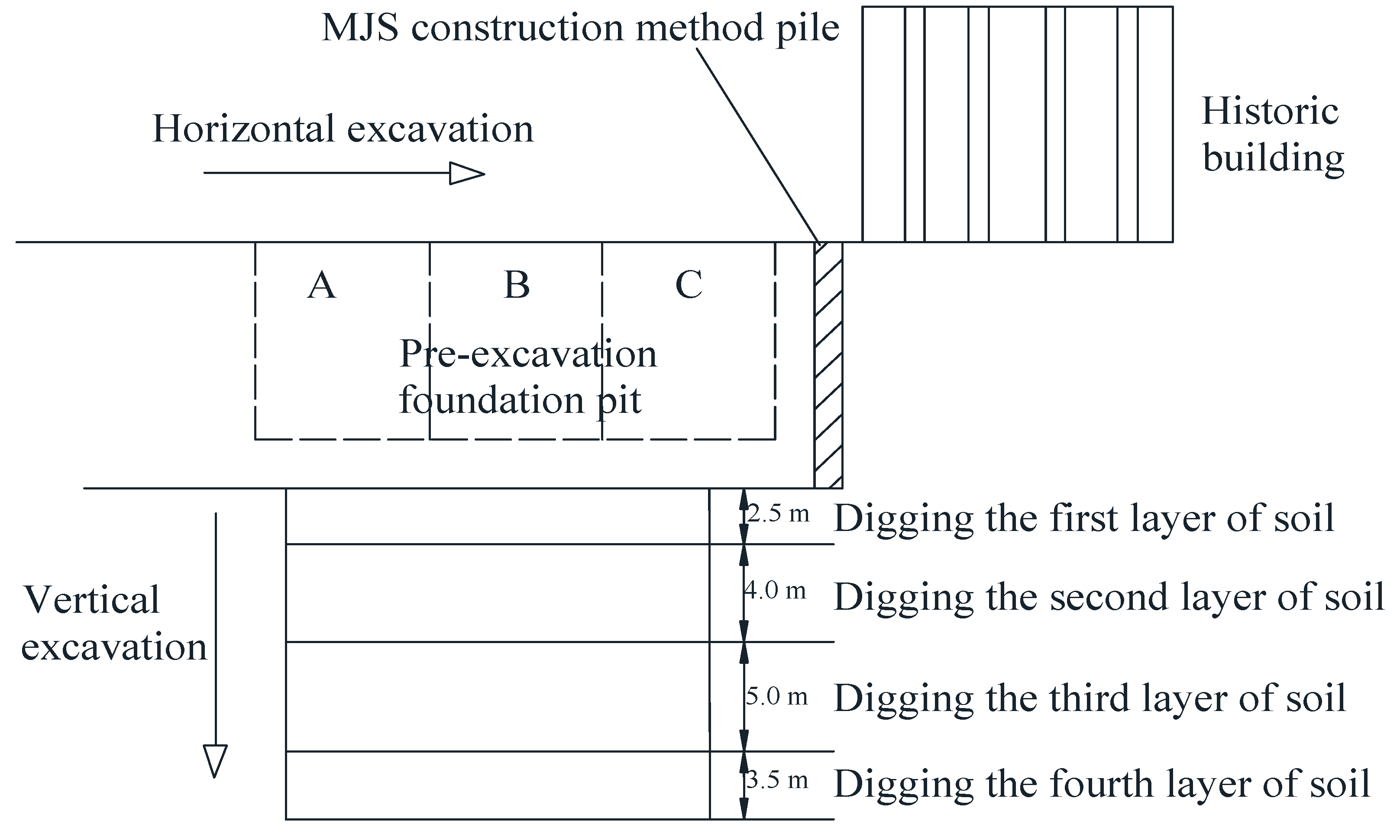
Due to a deep groundwater level in the study area, the influence of groundwater has not been analyzed in this study, as stated in the geological survey report. With consideration paid toward the construction environment and geological conditions, this foundation pit was excavated in layers and sections, with three working faces A, B and C in the horizontal direction and four vertical excavation layers. Vertically, after each layer of construction was completed, a layer of steel support was immediately erected to improve the stability of the foundation pit and reduce the impact on the surrounding environment. A schematic of the layered and segmented excavation of the foundation pit is shown in Figure 1.
2.2. Overview of Surrounding Building
Wenyuan Pavilion (an ancient building of national significance) is situated on the northwest side of the foundation pit, with a minimum distance of approximately 5.4 m from the pit. Given the protected status of Wenyuan Pavilion and its architectural significance, particular attention was paid to it throughout the construction process. The ancient building is approximately 19.5 m in length, 10.8 m in width and 8 m in height. The main structure is a two-story brick and wood structure, and the roof is overlapped with pine mortise and tenon. The foundation is built with bluestone and filled with lime and soil, with a width and depth of 0.5 m and 1.0 m, respectively. The wall is made of bricks and has a thickness of 30 cm. In order to monitor the settlement of buildings during construction, four monitoring points A1–A4 were set at four corners of the building, and a leveling instrument was used for settlement observation. At the same time, the locations of diaphragm walls B1 and B2 were selected, and the deformation was monitored using an inclinometer. A layout of the building and displacement monitoring points is illustrated in Figure 2.
3. Monitoring and Result Analysis of Foundation Pit Excavation
3.1. Time–History Curves of Horizontal Displacement of Diaphragm Wall
Figure 3 depicts the variation in the horizontal displacement of the diaphragm wall at B1 during different construction stages. As the excavation depth of the foundation pit increases, the horizontal displacement of the diaphragm wall gradually increases. Overall, the horizontal displacement of the diaphragm wall exhibits a fish-belly shape, meaning that as the depth increases, the horizontal displacement initially increases, then subsequently decreases. After completion of the four construction stages, the maximum horizontal displacement of the diaphragm wall is 1.9 mm, 3.8 mm, 7.8 mm and 9.6 m occurring at excavation depths of 0 m, 5 m, 7.2 m, and 9 m, respectively. As can be seen, with increasing excavation depth, the maximum horizontal displacement of the diaphragm wall gradually increases. In addition, after the completion of construction stages 2, 3 and 4, the top of the diaphragm wall experienced displacement towards the outside of the foundation pit. This is mainly due to the external force exerted by the internal support on the diaphragm wall, which suppresses the deformation of the diaphragm wall caused by the unloading of the foundation pit soil.
Figure 4 depicts the variation in the horizontal displacement of the diaphragm wall at B2 during different construction stages. From Figure 4, it can be seen that the deformation pattern of the diaphragm wall is the same as in Figure 3, but the overall deformation is greater, with a maximum deformation increase of about 8 mm. This is because the MJS pile effectively reduces the deformation of the diaphragm wall at B1.
3.2. Time–History Curve of Settlement of Ancient Building
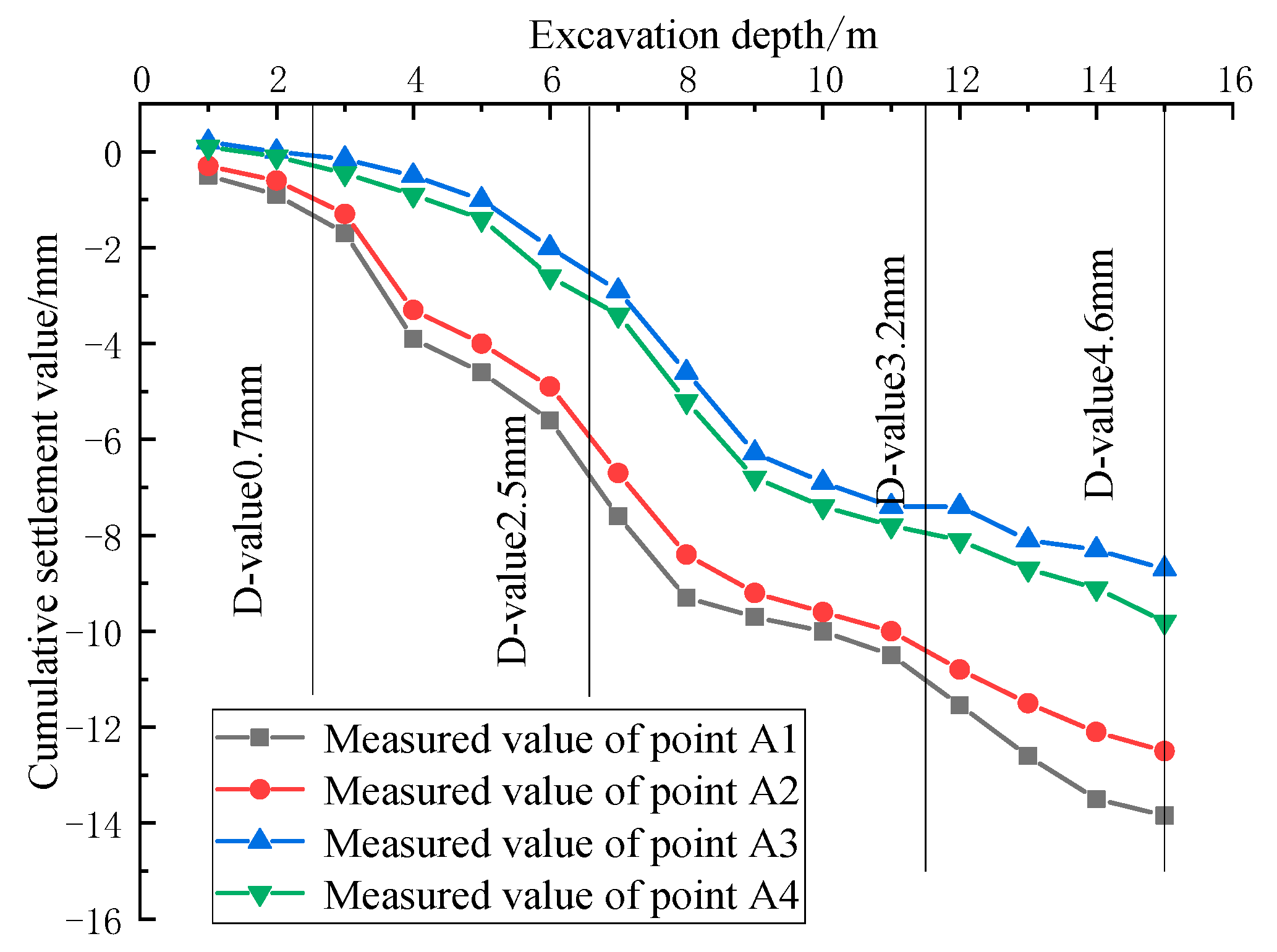
Regarding the monitoring points A1 to A4, compared to points A3 and A4, points A1 and A2 are closer to the foundation pit. In addition, A1 and A3 are located at the end of the foundation pit, while A2 and A4 are near the middle of the foundation pit. During the excavation process of the foundation pit, differential settlement may occur at different positions of the building, which may cause the building to incline. To investigate the inclination degree of the building, according to the excavation stages as presented in Table 1, the data obtained from monitoring points A1, A2, A3 and A4 were compared. The corresponding results are illustrated in Figure 5. As the excavation depth increases, the settlement of monitoring points A1 to A4 all show a trend of first increasing and then gradually leveling off. Among them, monitoring point A2 has the largest settlement, with a maximum value of approximately 13.84 mm. This is mainly due to the fact that this point is close to the foundation pit and located near to the middle of the foundation pit and, thus, more likely to be disturbed during excavation. After the completion of construction stages 1, 2, 3 and 4, the maximum settlement differences at each corner of the building are 0.7 mm, 2.5 mm, 3.2 mm and 4.6 mm, respectively. As the construction progresses through stages 1 through to 4, the maximum settlement difference of the building gradually increases, causing the overall building to incline towards the A2 direction, which can ultimately cause shear failure and cracking of the building wall.
4. Numerical Simulation
4.1. Establishment of Numerical Model
In this study, a three-dimensional model of the foundation pit is established using Midas GTS. In order to reduce the influence of the boundary effect in the horizontal direction, the distance between the model boundary and the edge of the foundation pit is more than three times greater than the depth of the foundation pit and, in the vertical direction, the distance is more than two times greater than the depth of the foundation pit. The dimensions of the established model are 150 m in length, 110 m in width, and 45 m in height. When establishing the model, the soil layer and building foundation adopt 3D solid elements, and 2D plate elements are adopted for the building wall, diaphragm wall and the foundation pit floor. The concrete support, crown beam, steel support and MJS pile are simulated using beam elements. When dividing the model into meshes, in order to ensure the calculation accuracy, the meshes of the foundation pit and building areas were appropriately densified. Figure 6 shows the established numerical model and its mesh division. The number of meshes in the model is 126,325, and the number of nodes is 93,194.
In the model, an MM–C (Modified Mohr–Coulomb) constitutive model is used to simulate the mechanical behavior of soils, and the physical and mechanical parameters are shown in Table 2. The MM–C model is an improved model developed by Midas GTS specifically to solve the problem of excessive soil uplift at the bottom of foundation pits. It takes into account the changes in the soil’s elastic modulus during unloading and reloading, which is more in line with engineering practices. By conducting tri-axial compression tests on soil samples, the strength and deformation relationship of each layer of soil can be obtained. Then, the strength parameters, including cohesion and friction angle, are obtained by fitting and regressing experimental data. Regarding the tri-axial test curve, the slope of the line between the 1/2 failure value and the origin is taken as , and usually = , and = 3 . When conducting numerical simulations, the back analysis method is adopted to continuously adjust the parameters of each soil layer, so that the numerical simulation results are as close as possible to the field monitoring results. In addition, the building wall, building foundation, foundation pit support structure and MJS pile are all regarded as elastic materials. Elastic constitutive models are adopted and the model parameters are shown in Table 3.
The boundary conditions of the model are as follows: the ground surface is a free surface; the lateral displacement around the soil is limited to zero and the vertical displacement is free; all displacements at the bottom boundary are constrained.
4.2. Comparison between Field Measurement and Numerical Calculation
- (1)
- Diaphragm Wall Deformation
The layout of monitoring points in the model corresponds to their actual positions, ensuring data consistency. Additionally, this enables a comprehensive evaluation of the reinforcement effect of the MJS pile. A comparison of the measured values and simulated values is presented in Figure 7.
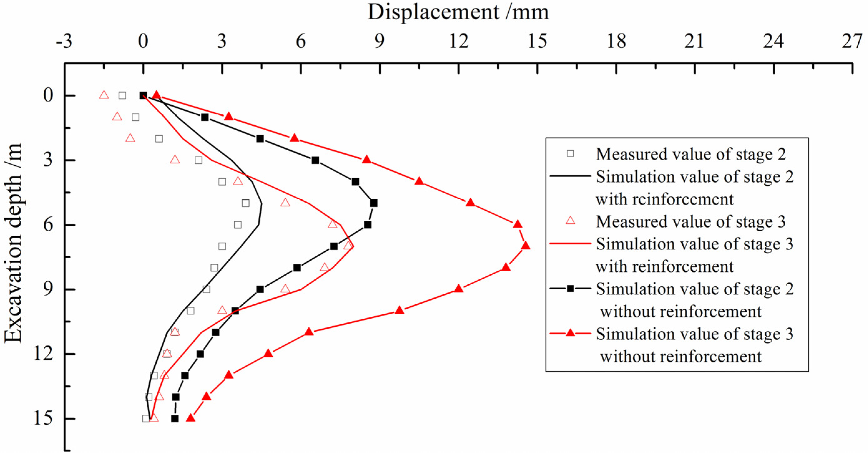
This study focuses on comparing the diaphragm wall deformation at monitoring point B1 during stages 2 and 3. This is because there is a significant difference in the diaphragm wall deformation between these two stages, which is more conducive to comparative analysis. Figure 7 reveals a consistent trend between the simulated values and field-measured data. At an excavation depth greater than 5 m, there is a certain deviation between the simulated value and the measured value, mainly due to the lack of consideration for the timeliness of field support construction during the simulation. By comparing simulated values with measured values, the goodness-of-fit values (R2) of stages 2 and 3 are 0.81 and 0.86, respectively. This indicates that the established numerical model can effectively simulate the excavation process of foundation pits. In addition, the absence of an MJS pile leads to diaphragm wall displacements greater than the measured values. This proves the effectiveness of MJS pile reinforcement in reducing lateral displacement and potential risks during the excavation of foundation pits.
- (2)
- Settlement of Ancient Building
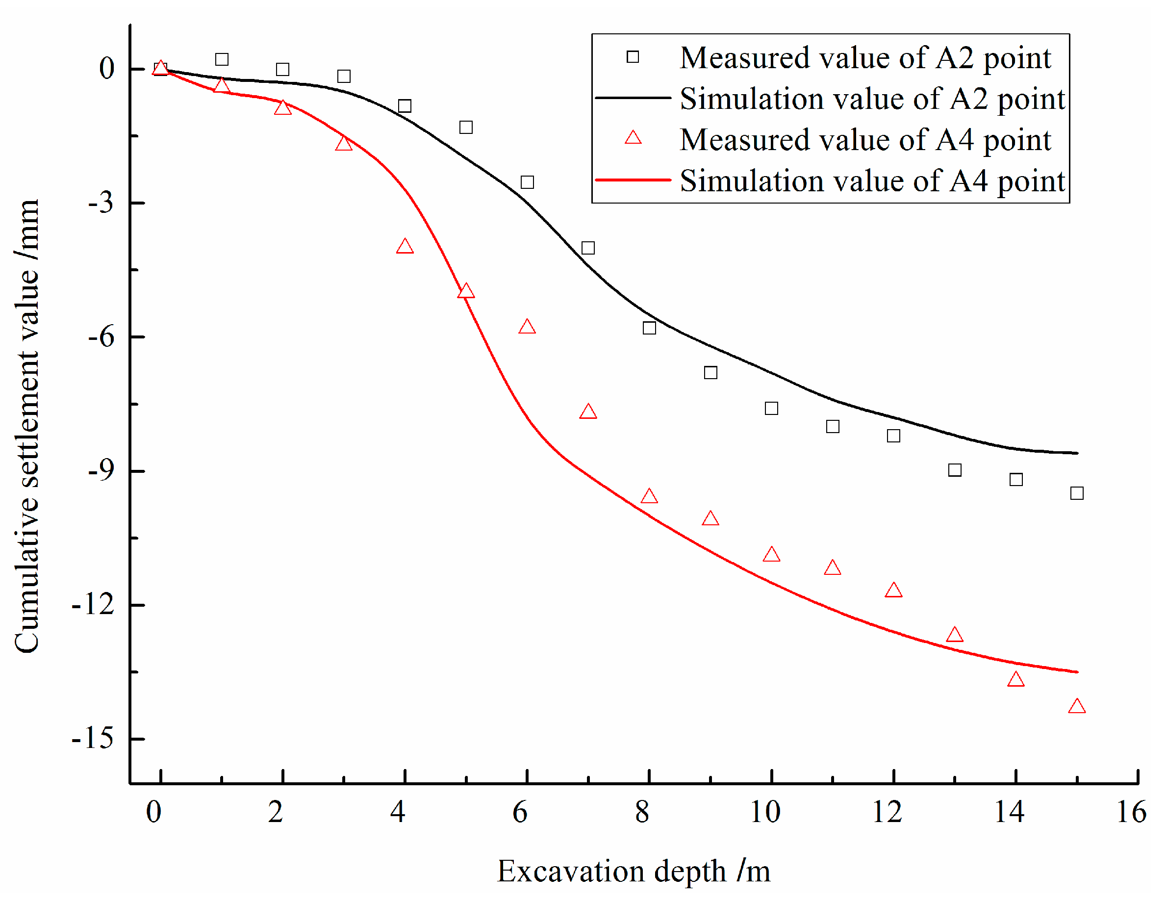
Similarly, the settlement values of two different monitoring points (A2 and A4) positioned on corners of the ancient building were selected for comparison. Figure 8 illustrates the comparison between the measured values and the simulated values.
As depicted in Figure 8, the results of numerical simulation, considering the reinforcement effect of the MJS pile, align closely with measured values. The goodness-of-fit values (R2) for the measured values and simulation values at A2 and A4 are 0.89 and 0.85, respectively. The overall variation trend between the two sets of data exhibits a high degree of similarity, with minimal discrepancies observed at each stage. These slight variations may stem from the influence of human and environmental factors as well as the inherent uncertainties associated with various parameters used in the numerical simulation.
4.3. Influence of Foundation Pit Excavation on Ground Settlement
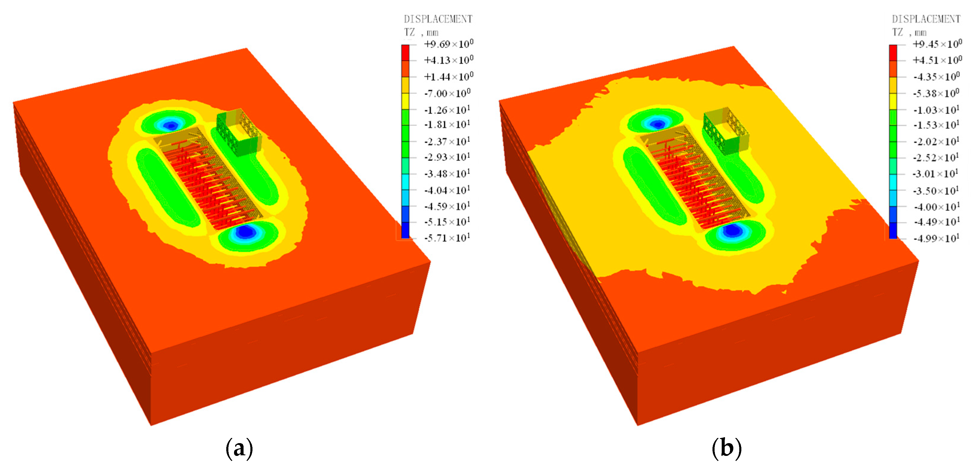
Figure 9 depicts a comparison of ground settlements around the foundation pit with and without MJS pile reinforcement. Overall, the ground settlement patterns around the foundation pit are basically consistent with and without MJS pile reinforcement. The closer to the foundation pit a measurement is made, the greater the surface settlement. Compared to the long side of the foundation pit, the surface settlement on the short side of the foundation pit is greater, mainly due to a lack of support there. In addition, after using an MJS pile for reinforcement, the surface settlement around the building is significantly reduced. Therefore, the MJS pile has a good reinforcement effect on the foundation pit and can better protect the surrounding buildings.
4.4. Influence of Foundation Pit Excavation on Adjacent Building
- (1)
- Settlement of Building
The vertical deformation of the front wall of the ancient building upon completion of foundation pit excavation with an MJS pile is shown in Figure 10. From the figure, it can be seen that the settlement of the building wall ranges from 7 to 15 mm. Moreover, the closer it is to the middle of the foundation pit, the greater the settlement of the wall, resulting in an incline of the wall towards the middle of the foundation pit.
The maximum settlement of the ancient building’s wall with and without the presence of an MJS pile during different construction stages is shown in Figure 11. It can be seen that as construction progresses through stages 1 to 4, the settlement of the wall gradually increases with an increase in excavation depth. Compared with not using an MJS pile, the settlement curve of the building’s walls with MJS pile reinforcement is relatively flat. In addition, the maximum settlement value of the building’s wall without MJS pile reinforcement reached 45 mm, which is approximately 3.6 times that of the building’s wall with MJS pile reinforcement. This indicates that the use of an MJS pile played a good protective role for ancient buildings.
- (2)
- Shear Strain of Building
Relevant research shows that the failure of buildings is usually caused by shear strain induced by uneven settlement of their structure [22]. Therefore, this paper uses the maximum shear strain as an indicator to evaluate the damage degree of the studied building, as shown in Table 4. The shear strain of the front wall of the building with and without MJS pile reinforcement is shown in Figure 12 and Figure 13. Using MJS pile reinforcement, the shear strain of the wall is less than 0.05%, and the degree of damage can be ignored. When there is no MJS pile reinforcement, the shear strain of the wall at the doors and windows is 0.1% to 0.15%, constituting a slight degree of damage, while the shear strain range at the corners is 0.15% to 0.3%, indicating a moderate degree of damage. This is mainly due to the stress concentration caused by the uneven settlement of the building in these areas, which can easily lead to cracks and damage in the doors, windows, and corners of the building. Through comparison, it can be seen that upon using an MJS pile, the impact of foundation pit excavation on the building’s walls is significantly reduced.
The maximum shear strain of the ancient building’s wall with and without MJS pile reinforcement during different construction stages is shown in Figure 14. It can be seen that as construction progresses through stages 1 to 4, the maximum shear strain of the wall gradually increases with increasing excavation depth. The increasing trend of shear strain without MJS pile reinforcement is more significant, with a maximum value of 0.26%, which is about three times the maximum shear strain when using MJS pile reinforcement.
From the previous analysis, it can be seen that foundation pit excavation influences the settlement of adjacent buildings. Therefore, the impact of excavation on the degree of damage to adjacent buildings can be evaluated by analyzing the relationship between the buildings’ settlement difference and the wall strain. Figure 15 depicts the relationship curve between the settlement difference and wall shear strain of the building under study. As the settlement difference increases, the maximum shear strain of the wall gradually increases, and the relationship resembles a logarithmic function. Due to the different distances between different parts of the building and the foundation pit, the less affected wall exerts a pulling effect on the wall closer to foundation pit, which causes shear force on the wall, resulting in shear strain.
4.5. Influence of MJS Pile Parameters on Building Settlement
- (1)
- Influence of MJS Pile Depth
The influence of MJS pile depth on the settlement difference of the ancient building under investigation is shown in Figure 16. As the depth of the MJS pile increases, the settlement difference of the ancient building gradually decreases. The impact of MJS pile reinforcement is primarily observed within the excavation depth range of 4 m to 12 m. However, when the length of the MJS pile exceeds 1.0 times that of H (where H represents the depth of the foundation pit), the impact of MJS pile depth on the building’s settlement difference is reduced. Therefore, the shear strain of the wall related to settlement differences is also reduced. From the perspectives of cost-effectiveness and practicality, the length of the MJS pile should be taken as one times the depth of the foundation pit.
- (2)
- Influence of MJS Pile Position
Figure 17 shows the influence of the MJS pile position on the building’s settlement difference. It can be seen that, for MJS piles set at different positions, the building’s settlement difference is consistent. Moreover, the closer the MJS pile is to the foundation pit, the smaller the differential settlement of the building. It can be seen that, when the MJS pile is closer to the foundation pit, its ability to resist lateral soil pressure becomes stronger, which in turn has a better isolation effect on the building and the foundation pit.
5. Conclusions
Based on a deep foundation pit in Xi’an, China, by means of field monitoring and numerical simulation, the deformation of a diaphragm wall and the settlement and deformation of an adjacent ancient building with and without MJS pile reinforcement are studied. The main conclusions obtained in this article are as follows:
- (1)
- As the excavation depth of the foundation pit increases, the horizontal displacement of the diaphragm wall increases, the settlement difference of the building increases and the building inclines toward the middle of the foundation pit.
- (2)
- The maximum shear strain of the building’s wall is caused by the settlement difference of the building, which mainly occurs on both sides of the doors and windows and on the left and right corners of the wall. During the construction of foundation pits, key monitoring and protection should be carried out in these areas.
- (3)
- Upon using MJS pile reinforcement, the deformation of the diaphragm wall is significantly reduced. The maximum settlement difference and wall deformation of the ancient building is only one third of that when foregoing MJS pile reinforcement, indicating that MJS pile reinforcement played a good protective role for the ancient building in question.
- (4)
- The closer the MJS pile is to the building or the deeper the MJS pile is, the smaller the building’s settlement difference. When the depth of the MJS pile is greater than one times the depth of the foundation pit, its reinforcement effect is not significantly improved. Therefore, the depth of MJS piles in engineering should be the same as the depth of foundation pits.
Funding
This work is supported by the National Natural Science Foundation of Chongqing (No. cstc2018jcyjAX0445) and Key projects of colleges and universities in Henan Province (No. 22B580001).
Data Availability Statement
The data used to support the findings of this study are available from the corresponding author upon request.
Conflicts of Interest
The author declares no conflict of interest.
References
- Han, M.; Li, Z.; Mei, G.; Bao, X.; Jia, J.; Liu, L.; Li, Y. Characteristics of subway excavation in soft soil and protective effects of partition wall on the historical building and pile foundation building. Bull. Eng. Geol. Environ. 2022, 81, 307. [Google Scholar] [CrossRef]
- Dmochowski, G.; Szolomicki, J. Technical and structural problems related to the interaction between a deep excavation and adjacent existing buildings. Appl. Sci. 2021, 11, 481. [Google Scholar] [CrossRef]
- De Vita, M.; Massari, G.; De Berardinis, P. Retrofit methodology based on energy simulation modeling applied for the enhancement of a historical building in L’Aquila. Energies 2020, 13, 3289. [Google Scholar] [CrossRef]
- Xue, H.J. Research on the control of excavation deformation of super deep foundation pit adjacent to the existing old masonry structure building. Sustainability 2023, 15, 7697. [Google Scholar] [CrossRef]
- Wei, H. Influence of foundation pit excavation and precipitation on settlement of surrounding buildings. Adv. Civ. Eng. 2021, 2021, 6638868. [Google Scholar] [CrossRef]
- Wang, G.; Chen, W.; Cao, L.; Li, Y.; Liu, S.; Yu, J.; Wang, B. Retaining technology for deep foundation pit excavation adjacent to high-speed railways based on deformation control. Front. Earth Sci. 2021, 9, 735315. [Google Scholar] [CrossRef]
- Angiolilli, M.; Gregori, A.; Cattari, S. Performance of fiber reinforced mortar coating for irregular stone masonry: Experimental and analytical investigations. Constr. Build. Mater. 2021, 294, 37–42. [Google Scholar] [CrossRef]
- Boone, S.J.; Westland, J.; Nusink, R. Comparative evaluation of building responses to an adjacent braced excavation. Can. Geotech. J. 1999, 36, 210–223. [Google Scholar] [CrossRef]
- Zhao, Y.S.; Wang, B.L.; Zhou, S.H. Monitoring and analysis of the influence of foundation pit excavation on adjacent buildings. Undergr. Space 2000, 20, 51–53. (In Chinese) [Google Scholar]
- Ou, C.Y.; Teng, F.; Li, C.W. A simplified estimation of excavation-induced ground movements for adjacent building damage potential assessment. Tunn. Undergr. Space Technol. 2020, 106, 103561. [Google Scholar] [CrossRef]
- Zhao, C.; Feng, Y.; Wang, W.; Niu, Z. Mechanical properties and numerical analysis of underground continuous wall in underground grain silo foundation pit. Buildings 2023, 13, 293. [Google Scholar] [CrossRef]
- Wu, J.; Ye, S.; Wang, Z.; Yang, D. Application and automatic monitoring and analysis of hybrid support structure in ultra-deep foundation pit engineering in the Lanzhou area under complex environmental conditions. Water 2023, 15, 1335. [Google Scholar] [CrossRef]
- Górska, K.; Muszyński, Z.; Rybak, J. Displacement monitoring and sensitivity analysis in the observational method. Stud. Geotech. Et Mech. 2013, 35, 25–43. [Google Scholar] [CrossRef]
- Zhang, J.; Chen, Z.; Hu, M.; Wu, Z. Study on deep and large foundation pit of a national first-class key tomb protection project. Adv. Civ. Eng. 2021, 2021, 1–12. [Google Scholar] [CrossRef]
- Chen, W.; Wei, X.; Fan, J.; Yang, K.; Yao, X. Monitoring analysis of a deep foundation pit construction adjacent to old buildings. IOP Conf. Ser. Mater. Sci. Eng. 2020, 780, 052015. [Google Scholar] [CrossRef]
- Li, Z.; Han, M.; Liu, L.; Li, Y.; Yan, S. Corner and partition wall effects on the settlement of a historical building near a supported subway excavation in soft soil. Comput. Geotech. 2020, 128, 103805. [Google Scholar] [CrossRef]
- Wang, G. Optimization of seismic reinforcement technology for multi-storey brick masonry structures under differential settlement. Sci. Technol. Eng. 2018, 18, 194–200. [Google Scholar]
- Tang, M.F.; Pu, M.; Gui, J.G. Analysis on influence of excavation of metro station's deep foundation pit upon adjacent buildings. Railw. Eng. 2014, 1, 88–90. (In Chinese) [Google Scholar]
- Zhai, J.Q.; Jia, J.; Xie, X.L. Practice of partition wall in the building protection projects near deep excavation. Chin. J. Undergr. Space Eng. 2010, 6, 162–166. (In Chinese) [Google Scholar]
- Ying, H.W.; Li, T.; Wang, W.F. Optimization design of partition wall in deep excavations based on 3-D numerical simulation. Rock Soil Mech. 2012, 33, 220–226. (In Chinese) [Google Scholar]
- Wu, C.J.; Zhang, Z.X.; Ding, W.Q.; Zhang, D.Y. Influences of construction of side-crossing shield tunnel on adjacent ancient architectures and reinforcement effect of protection measures. Chin. J. Geotech. Eng. 2012, 34, 158–165. (In Chinese) [Google Scholar]
- Boscardin, M.D.; Cording, E.J. Building response to excavation-induced settlement. J. Geotech. Eng. 1989, 115, 1–21. [Google Scholar] [CrossRef]
Figure 1.
Schematic diagram of layered and segmented excavation of foundation pit.

Figure 2.
Schematic diagram of the building and monitoring points around the foundation pit.

Figure 3.
Horizontal displacement curve of diaphragm wall at B1.

Figure 4.
Horizontal displacement curve of diaphragm wall at B2.

Figure 5.
Settlement curves for four monitoring points positioned on corners of ancient building.

Figure 6.
Numerical model.

Figure 7.
Comparison of measured values and simulated values at monitoring point B1.

Figure 8.
Comparison curve between measured and simulated settlement of ancient building.

Figure 9.
Comparison of ground settlement with and without MJS pile. (a) Without MJS pile; (b) with MJS pile.
Figure 9.
Comparison of ground settlement with and without MJS pile. (a) Without MJS pile; (b) with MJS pile.

Figure 10.
Wall settlement of adjacent ancient building caused by foundation pit excavation with MJS pile.
Figure 10.
Wall settlement of adjacent ancient building caused by foundation pit excavation with MJS pile.

Figure 11.
Maximum settlement of ancient building wall with and without MJS pile under different construction stages.
Figure 11.
Maximum settlement of ancient building wall with and without MJS pile under different construction stages.

Figure 12.
Shear strain diagram of the ancient building wall with MJS pile.

Figure 13.
Shear strain diagram of ancient building wall without MJS pile.

Figure 14.
Maximum shear strain of ancient building wall with and without MJS pile during different construction stages.
Figure 14.
Maximum shear strain of ancient building wall with and without MJS pile during different construction stages.

Figure 15.
Relationship between the building settlement difference and wall shear strain.

Figure 16.
Influence of MJS pile depth on ancient building settlement.

Figure 17.
Influence of MJS pile positions on building settlement.


Table 1.
Foundation pit construction stages.
| Process Name | Foundation Pit Support | Excavation Depth | Construction Remarks |
|---|---|---|---|
| Construction Preparation | — | 0 m | Underground diaphragm wall construction |
| Excavation Stage 1 | Set up the first support | 2.5 m | Reinforced concrete support |
| Excavation Stage 2 | Set up the second support | 6.5 m | Steel support |
| Excavation Stage 3 | Set up the third support | 12 m | Steel support |
| Excavation Stage 4 | Pour foundation pit floor | 15 m | —— |
Table 2.
Physical and mechanical parameters of soil.
| Soil Thickness (m) | Soil Type | Cohesion (kPa) | Friction Angle (º) | Unit Weight (kN/m3) | Poisson’s Ratio | (kPa) | (kPa) | (kPa) |
|---|---|---|---|---|---|---|---|---|
| 0–3 | Miscellaneous Fill | 5.5 | 4.2 | 17 | 0.32 | 5200 | 5200 | 15,600 |
| 3–6.5 | Muddy Clay | 18.2 | 17.5 | 18.5 | 0.28 | 6000 | 6000 | 18,000 |
| 6.5–8 | Silty Clay | 8.6 | 12.6 | 18 | 0.35 | 8700 | 8700 | 26,100 |
| 8–12 | Hard Plastic Silty Clay | 26.1 | 28.6 | 19.5 | 0.28 | 14,500 | 14,500 | 43,500 |
| 12–23 | Strongly Weathered Argillaceous Siltstone | 20.5 | 3.5 | 23.2 | 0.32 | 23,000 | 23,000 | 69,000 |
Table 3.
Physical and mechanical parameters of buildings and foundation pit support structure.
| Structure Type | Elastic Modulus (MPa) | Unit Weight (kN/m3) | Poisson’s Ratio |
|---|---|---|---|
| Crown Beam | 25,000 | 25 | 0.2 |
| Diaphragm Wall | 25,000 | 25 | 0.2 |
| Concrete Support | 25,000 | 25 | 0.2 |
| Steel Support | 210,000 | 78 | 0.3 |
| MJS Pile | 400 | 18 | 0.32 |
| Building Wall | 2000 | 23 | 0.25 |
| Building Foundation | 2000 | 23 | 0.25 |
Table 4.
Relationship between shear strain and structural damage degree.
| Maximum Shear Strain/% | Damage Degree of Building |
|---|---|
| 0–0.05 | Negligible |
| 0.05–0.15 | Slight |
| 0.15–0.3 | Medium |
| >0.3 | Serious |
Disclaimer/Publisher’s Note: The statements, opinions and data contained in all publications are solely those of the individual author(s) and contributor(s) and not of MDPI and/or the editor(s). MDPI and/or the editor(s) disclaim responsibility for any injury to people or property resulting from any ideas, methods, instructions or products referred to in the content. |
© 2023 by the author. Licensee MDPI, Basel, Switzerland. This article is an open access article distributed under the terms and conditions of the Creative Commons Attribution (CC BY) license (https://creativecommons.org/licenses/by/4.0/).
Share and Cite
MDPI and ACS Style
Zhang, D. Influences of Deep Foundation Pit Excavation on the Stability of Adjacent Ancient Buildings. Buildings 2023, 13, 2004. https://doi.org/10.3390/buildings13082004
AMA Style
Zhang D. Influences of Deep Foundation Pit Excavation on the Stability of Adjacent Ancient Buildings. Buildings. 2023; 13(8):2004. https://doi.org/10.3390/buildings13082004
Chicago/Turabian StyleZhang, Dandan. 2023. "Influences of Deep Foundation Pit Excavation on the Stability of Adjacent Ancient Buildings" Buildings 13, no. 8: 2004. https://doi.org/10.3390/buildings13082004
Note that from the first issue of 2016, this journal uses article numbers instead of page numbers. See further details here.