Article

Aluminium Bridges under Fire Conditions: Structural Behaviour

by
Fedor Aleksandrovich Portnov
* and
Dmitry Aleksandrovich Korolchenko
Moscow State University of Civil Engineering, Yaroslav Shosse, 26, 129337 Moscow, Russia
*
Author to whom correspondence should be addressed.
Buildings 2023, 13(7), 1669; https://doi.org/10.3390/buildings13071669
Submission received: 28 May 2023 / Revised: 26 June 2023 / Accepted: 26 June 2023 / Published: 29 June 2023
(This article belongs to the Collection Buildings and Fire Safety)

Abstract

:
Due to a number of advantages, aluminium is used in the attachment units of mullion and transom systems for decorative panels and translucent fillings, as well as for bridge structures. Despite its advantages, aluminium has a low melting point and does not have fire resistance performances required by regulatory documents under fire conditions. Therefore, this article is aimed at studying the behaviour of aluminium structures under high temperatures. To achieve this objective, we have analysed the aluminium structures most commonly used in construction—the attachment units of mullion and transom systems, with different protections against fire, columns and orthotropic decks used in bridge construction. In order to assess the behaviour of selected structures under fire conditions, we have developed methods for studying temperature distributions in structures in detail. Using the developed methods, tests have been carried out. Based on the received experimental data, we analysed the behaviour of aluminium structures in fire conditions and developed measures to increase the fire resistance of aluminium structures. Such measures include using hollow profiles to ensure air exchange with the cold sections of the structure, applying dedicated cooling agents to cool the structure and removing heat to the atmosphere and thermal barriers so as to protect aluminium structures. We found that fire resistance measures enhance the fire resistance of aluminium attachment units of mullion and transom systems by 1.5 times. The use of hollow air-permeable profiles and cooling agents in orthotropic decks increases fire resistance by 3 times by removing heat from the structures. The fire resistance rating of hollow profile aluminium columns is 1.5 times higher than that of structures without air-permeable profiles. The obtained results can be used as the most effective basis for the design of aluminium structures. The principles of increasing fire resistance given in this article are applicable to other types of structures, and can also be used with other methods of fire protection. Increasing the fire resistance of aluminium structures enables the expansion of the scope of their applications.

1. Introduction

The global bridge construction industry prefers heavy steel sections and light weight thin-walled steel components (Figure 1). It is well-known that reinforced concrete structures have multiple advantages [1,2,3,4]. However, due to the technological properties of bridge structures, the use of reinforced concrete structures in this area is limited. The general development trend for this type of construction focuses on reducing the weight of structures. However, decreasing the transformed sections of the structures can lower their fire resistance. A large range of measures were developed for such structures to ensure stability under extreme conditions, including fire [5,6,7,8].
One of the main measures to improve fire resistance is using thin layer intumescent coating materials and structural fire protection [9,10]. In the last five years, measures and rules have been developed for designing aluminium bridge structures aimed at ensuring their light weight, easy assembly and operation [11,12,13]. This has significantly increased the relevance of aluminium structures in the building industry. Aluminium structures are used for building bridges [14,15,16,17,18,19]. Moreover, aluminium is used to produce elements of lightweight structures [20,21,22].
Aluminium structures have multiple advantages. Therefore, they are preferred for certain types of building structures. These advantages include the physical properties and manufacturing process of aluminium elements. The physical properties comprise their light weight and high corrosion resistance. Thus, they can be used without additional corrosion protections even in corrosive environments. The process of aluminium structure production is based on extrusion. As a result, it is possible to produce profiles with cross sections that provide maximum rigidity and functionality [23,24,25,26].
The main disadvantage of aluminium that limits its application is the low melting point. It can lead to the destruction of both aluminium construction elements (attachment units) and whole aluminium structures. There is a need to study the behaviour of aluminium structures in fire conditions and develop structures capable of preserving the bearing capacity for a long time. The latter can be achieved by correctly selecting acceptable loads on the structures [27,28].
One of the most popular cases for aluminium utilisation in construction is in attachment units of mullion and transom systems for decorative panels and translucent fillings. Aluminium is used in these structures since it is easy to manufacture profiles of complex forms and the structure is lightweight. These systems can be attached in the area of the slab ends, completely covering this area, or used for the translucent filling of the building’s façade. The site and structural properties of attachment units of decorative and translucent panels determine the attachment options to two (top and bottom or side) or four structure ends.
A more significant (in terms of responsibility) use case for aluminium is bridge structures. The main structural elements are aluminium orthotropic decks and columns. The evident advantages of aluminium structures are that they are lightweight and easy to manufacture, in addition to presenting a high corrosion resistance. However, since aluminium has a low melting point, it can be hard to ensure the necessary fire resistance level of such structures [29]. In a number of cases, columns with a channel section were considered [30]
One option is using the structural fire protection method that is very popular for load-bearing steel elements of industrial and civil building structures [23,31]. This is due to the need to ensure the building structures’ high fire resistance, which is unattainable when using fire-retardant paints and varnishes. However, using such methods to improve fire resistance can significantly reduce the advantages of aluminium structures. Structural fire protection methods add considerably to the cost and weight of structures. Furthermore, materials used for them have a much shorter service life compared to that of aluminium structures. This is due to the fact that thermal insulation materials have high moisture absorption rates and their fire-retardant effectiveness decreases, which leads to a need to replace these materials. The use of gypsum- and cement-based materials requires additional conditions for the installation and significantly increases the weight of the structures [4,5,6,32].
The aim of the research is to study the behaviour of aluminium structures under high temperatures.
To achieve this, the following objectives were set:
to develop a method for testing selected structures;
to identify boundary conditions of various aluminium structures related to the losses of the bearing capacity, the integrity and the heat-insulating capacity;
to identify the relation between the fire resistance level of attachment units of mullion and transom systems with aluminium and the fire protection method;
to assess the heating level of the aluminium orthotropic deck consisting of connected hollow profiles;
to identify the relation between the fire resistance of aluminium columns of different sections and the load;
to determine the main technological solutions to improve the fire resistance of various aluminium structures.
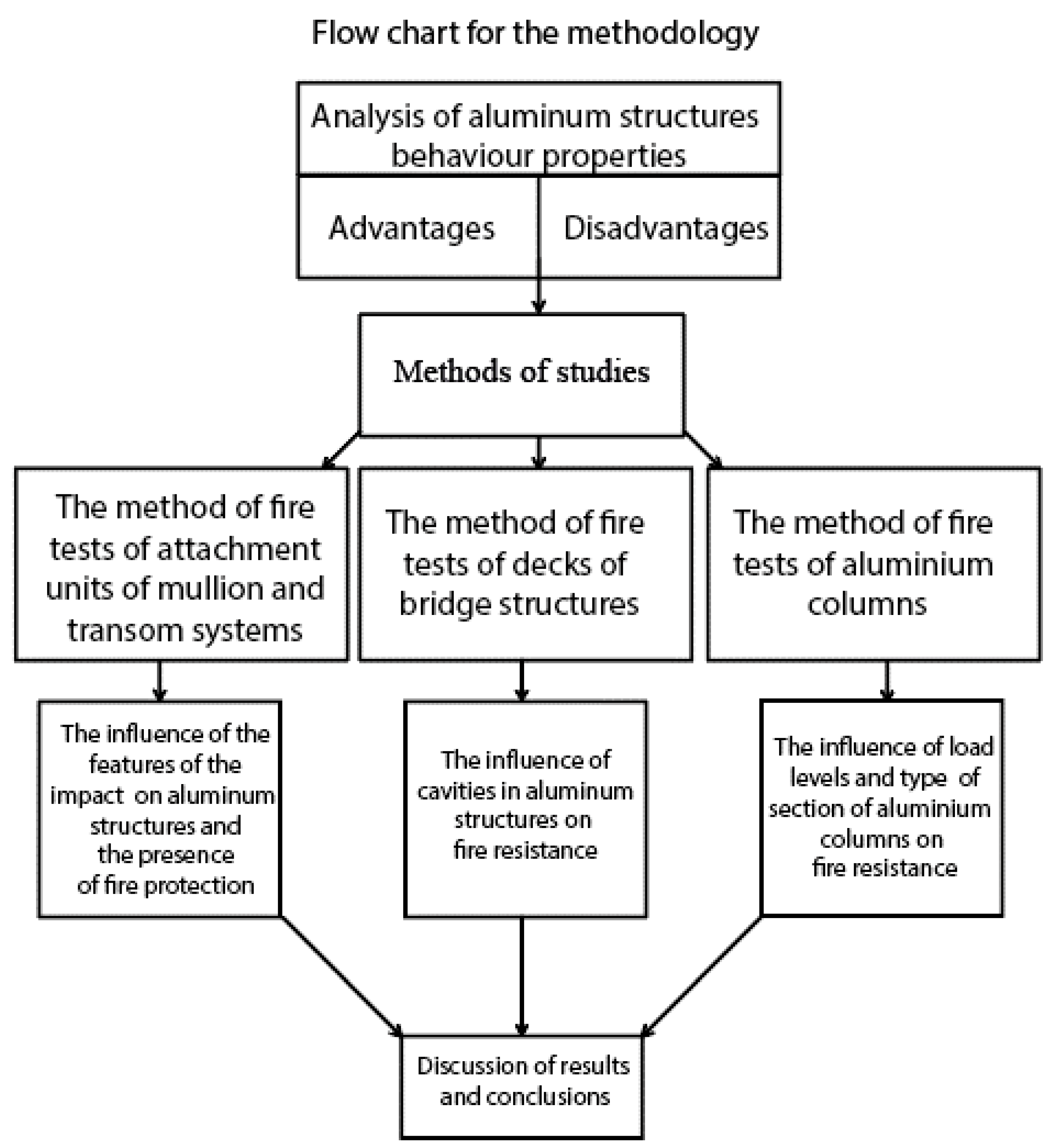
2. Methodology

2.1. Subject of Studies

To assess the behaviour of aluminium structures under fire conditions, we selected the following subjects for the study: the attachment unit of the mullion and transom system; the aluminium orthotropic deck; and the aluminium columns of various sections. The attachment unit of the mullion and transom system consists of the protective casing, the mullion and transom system and the attachment elements. The protective casing, which has a decorative function, among others, is made from a profiled zinc-coated sheet, with a thickness of 0.5 mm on the outside and 0.7 mm on the inside close to the structure, and it is filled with heat insulator. Zinc-coated sheets are attached to the test furnace opening with temporary nails. The joints of zinc-coated sheets and structures are sealed with a firestop sealant. The aluminium mullion and transom system is installed in the unit. For this test, the translucent filling was replaced by the 12.5 mm thick fire-resistant cement slab. Adhesive anchors, pins and supporting brackets installed above and below the system and bearing the main load of the structure are used as attachment elements.
There are two options as regards the attachment units. The first one has a protective non-inflammable heat-insulating membrane between the mullion and transom system and the casing, and the second one has no membrane—instead, the heated side of the mullion and transom system is covered with a 12.5 mm thick fire-resistant cement slab.
The aluminium orthotropic deck measures 4000 mm × 2000 mm in size and 170 mm in height, and consists of 300 mm wide and 170 mm high joined extruded triangular hollow profiles.
To study aluminium columns, we selected rectangular aluminium profile columns of the following dimensions:
300 mm × 150 mm × 15 mm columns, 2500 mm in height, 10 items;
200 mm × 120 mm × 12 mm columns, 2000 mm in height, 9 items;
160 mm × 100 mm × 8 mm columns, 2000 mm in height, 9 items.
The columns were subject to loads equal to section stress levels of 0%, 25%, 50%, 75% and 95% of the design strength as part of the study.
The column names and loads required to create the respective stress levels in individual sections are presented in Table 1.

2.2. Study Methods

To implement the study, a block diagram of the study was developed, as shown in Figure 2.
To study all types of described structures, the following equipment was used: test furnaces simulating a “standard” fire impact described with the formula T − T0 = 345 log (8t + 1), where T is the temperature in the heating chamber at the distance of 100 mm from the tested object, tis the testing time in minutes, and T0 is the initial temperature. Testing was conducted at an ambient temperature of 20–30 °C and a 0.5 m/s maximum wind speed. The common criteria for assessing all tests are the temperatures in the furnace and on the unheated surfaces of tested objects, the deformations of the tested objects, the times of flame occurrence on the unheated surfaces of tested objects, the times of occurrence and the properties of cracks, holes, delaminations and other phenomena (for example, violation of supporting conditions, smoke).

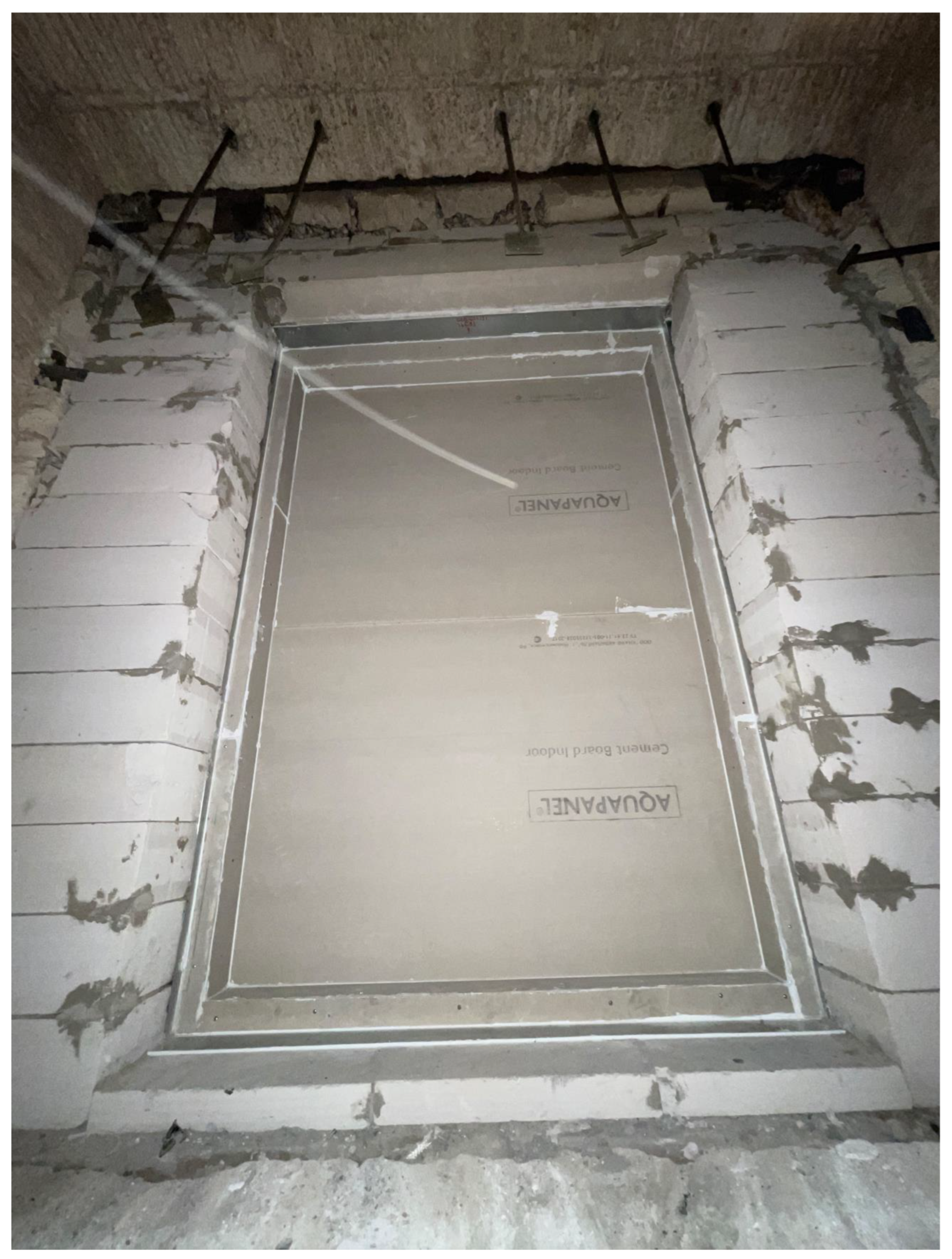
2.2.1. The Method of Fire Tests on the Attachment Units of Mullion and Transom Systems

To analyse the behaviour of aluminium elements of attachment units of mullion and transom systems, we selected the layout shown in Figure 3. According to the layout, the attachment unit of the mullion and transom system was mounted on the testing furnace with the vertical opening. To control the attachment unit of the mullion and transom system during the test, thermoelectric transducers were installed: one on the elements connecting the attachment unit of the mullion and transom system to the structure and bearing the main load of the attachment unit, and the others on the unheated surfaces in the areas subjected to the most heat.
The criteria for assessing the fire resistance of attachment units of mullion and transom systems are the ultimate limit states related to the losses of the bearing capacity (R), integrity (E) and heat-insulating capacity (I). The loss of the bearing capacity (R) is determined by the maximum vertical deformation of the retaining anchor at 6 mm and the maximum deformation build-up speed at 0.2 mm/min. The integrity loss (E) is determined by through cracks and holes in the structure and burning products and flame penetrating to the unheated surface through them. The integrity loss is assessed by a special cotton pad placed in a metal frame with a holder and brought close to areas of expected penetration of flame and burning products for 10 s at a 20–25 mm distance from the attachment unit of the mullion and transom system. The loss of the heat-insulating capacity (I) is determined by the temperature rise in the unheated surface of the structure by over 199 °C, taking into account the initial sample temperature of 19 °C.

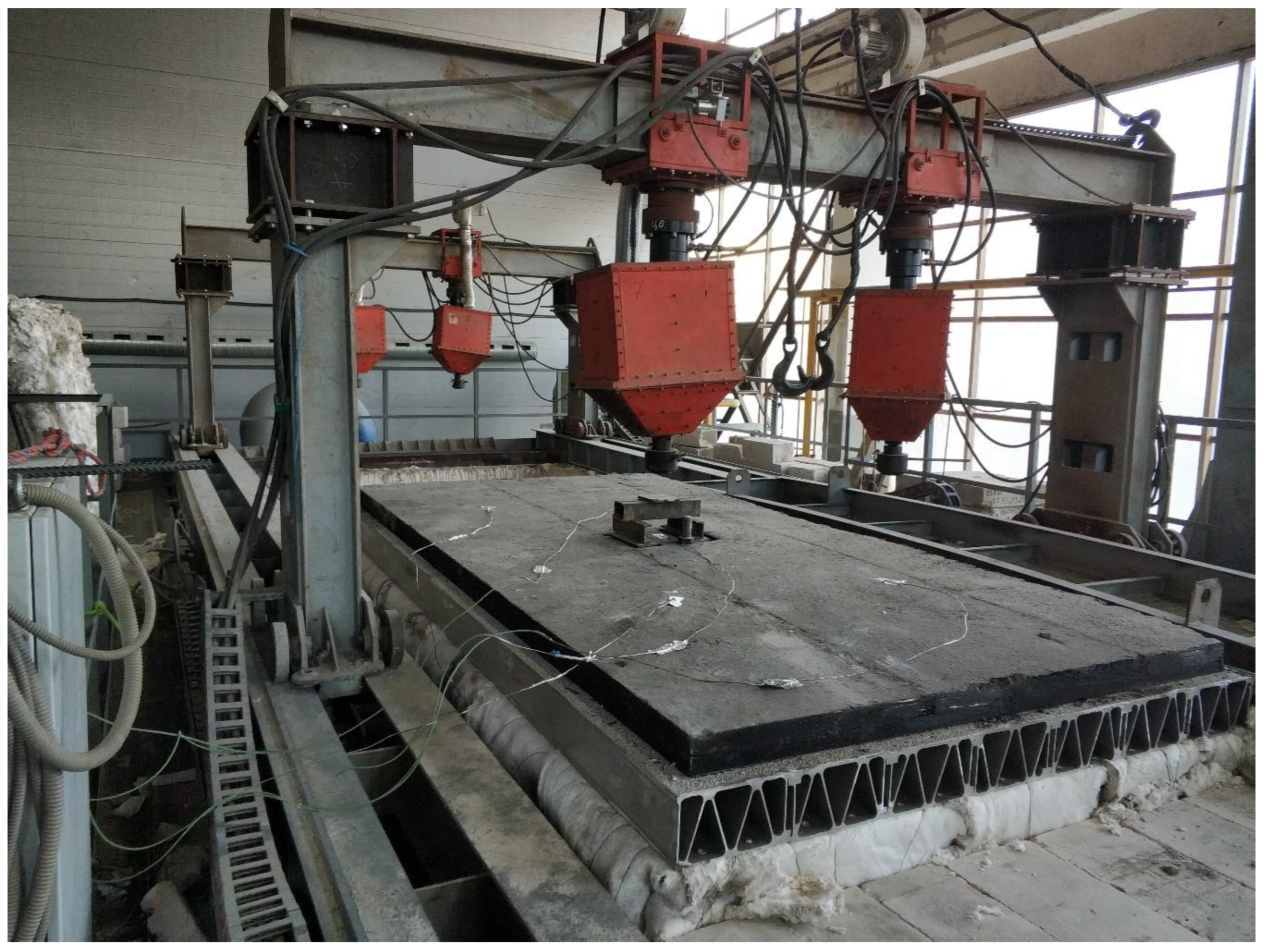
2.2.2. The Method of Fire Tests on Decks of Bridge Structures

Aluminium orthotropic decks were installed in the test furnace with a horizontal opening. The total load on the deck amounted to 7 tf. The load point is shown in Figure 4.
To control the temperature of the unheated surface of the aluminium orthotropic deck, one thermoelectric transducer was placed at the centre and the others were placed in the middle of the direct lines connecting the centre and corners of the furnace opening (T1–T5 in Figure 5). The temperatures in the aluminium orthotropic deck profile section were controlled using thermoelectric transducers (T6–T8), installed according to Figure 6.
The criteria for assessing fire resistance of orthotropic decks are the ultimate limit states related to the losses of the bearing capacity (R), integrity (E) and heat-insulating capacity (I). The loss of the bearing capacity (R) is determined by the maximum vertical deformation at 200 mm and the maximum deformation build-up speed at 200 mm/min. The integrity loss (E) is determined by the cracks and holes in the structure, burning products and the flames penetrating to the unheated surface through these fissures. The integrity loss is assessed using a special cotton pad placed in a metal frame with a holder and brought close to areas of expected penetration of flame and burning products for 10 s at a 20–25 mm distance from the surface of the aluminium orthotropic deck. The loss of the heat-insulating capacity (I) is determined by the temperature rise in the unheated surface of the structure by over 191.9 °C, taking into account the initial sample temperature of 11.9 °C.

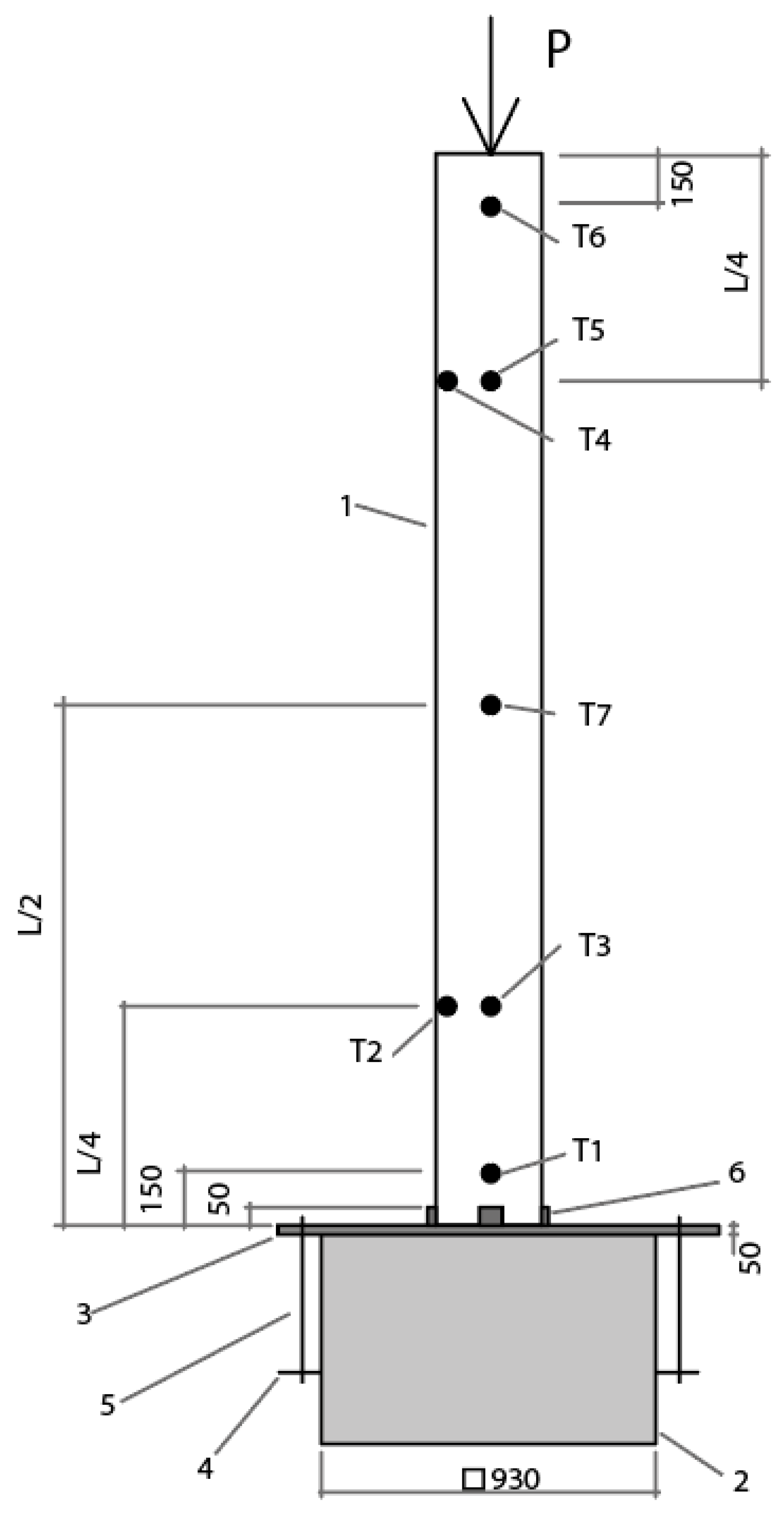
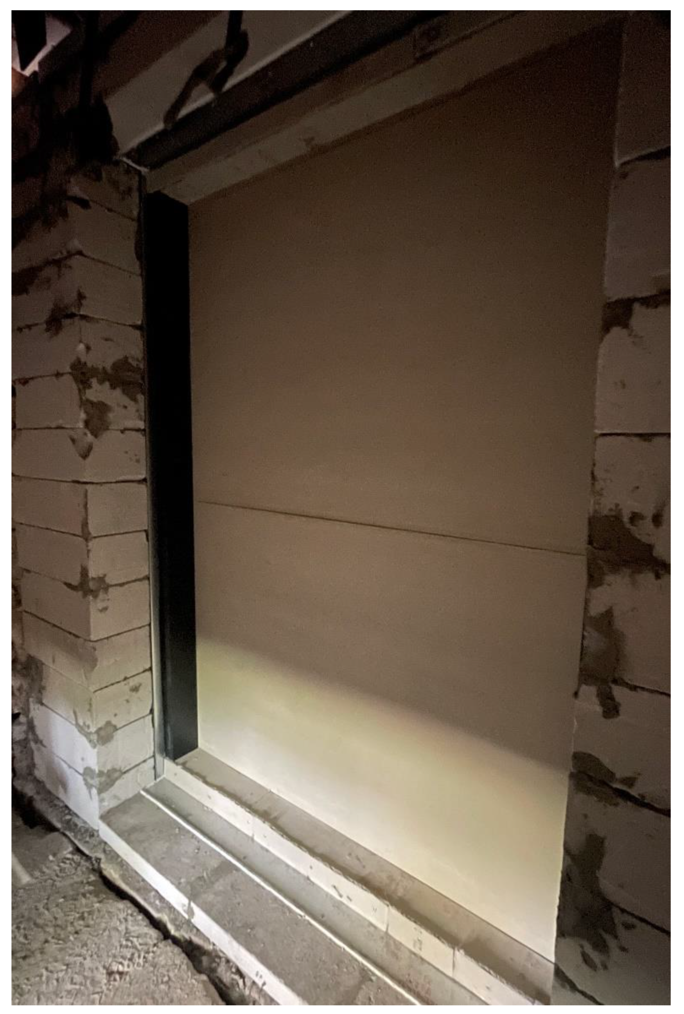
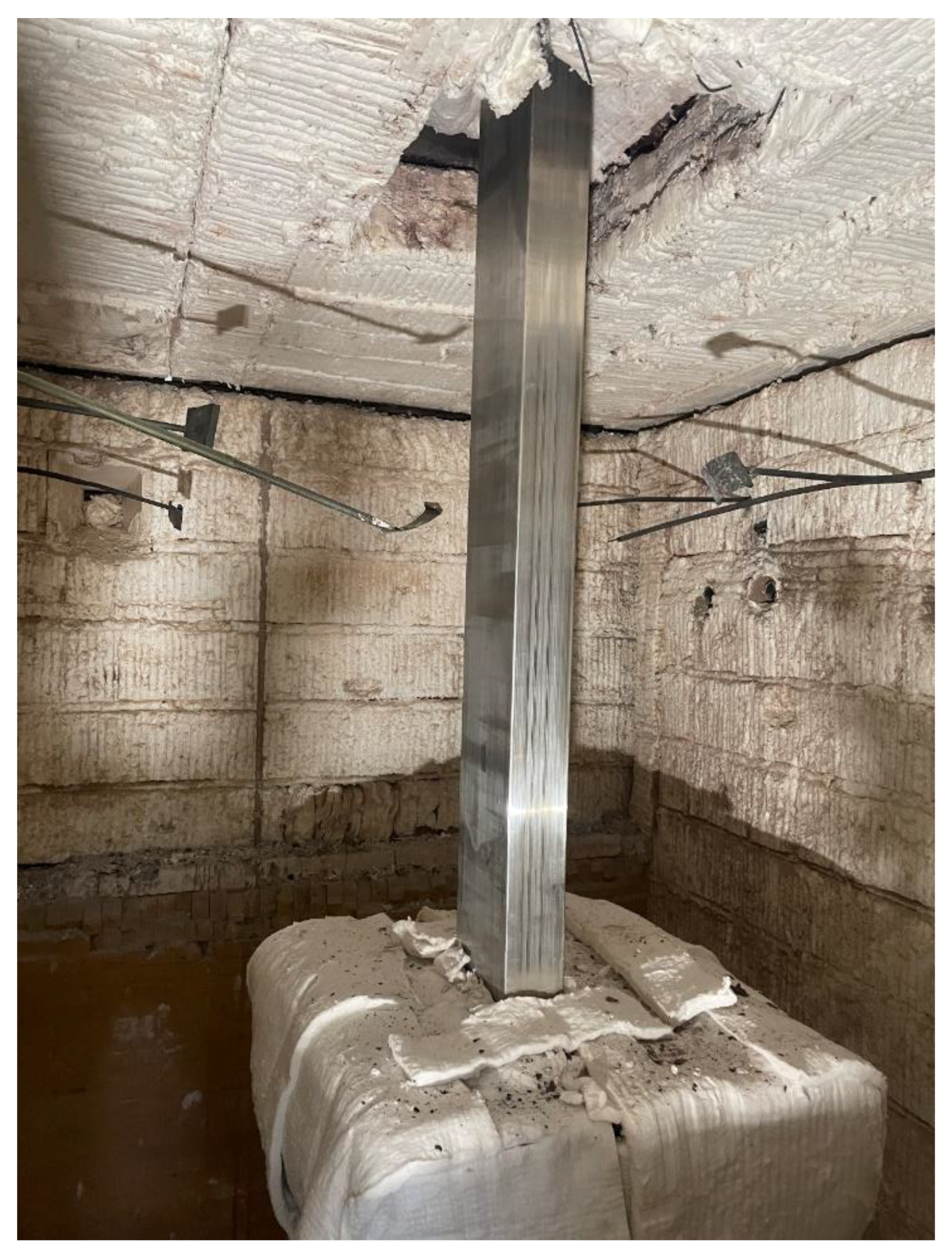
2.2.3. The Method of Fire Tests on Aluminium Columns

Aluminium columns are placed inside the test furnace with a vertical load capacity and four-sided heat exposure. The tests determine the time in minutes from the start of heat exposure to the time when the ultimate limit states are reached.
The criteria for assessing the fire resistance of aluminium columns are the ultimate limit states related to the loss of the bearing capacity (R) and the maximum temperature of the structure. The loss of the bearing capacity (R) is determined by the maximum vertical deformations of 250 mm for the 2500 mm high column and 200 mm for the 2000 mm high column at a maximum deformation build-up speed of 10 mm/min. The maximum temperature is 400 °C in the aluminium column interior. To measure the temperature of the aluminium columns, thermoelectric transducers were installed in the interior along the height of the aluminium columns (Figure 7):
T1 on the wall at a 150 mm distance from the bottom;
T2 on the corner at an L/4 mm distance from the bottom;
T3 on the wall at an L/4 mm distance from the bottom;
T4 on the corner at an L/4 mm distance from the top;
T5 on the wall at an L/4 mm distance from the top;
T6 on the wall at a 150 mm distance from the top;
T7 on the wall at the centre of the height.

3. Results

3.1. Attachment Units of Translucent Panels Using Aluminium Mullion and Transom System

Figure 8 shows the unheated side of the attachment units before testing.
Figure 9 shows the heated side of the attachment unit of the mullion and transom system with a protective non-inflammable heat-insulating membrane before testing.
The ultimate limit state of the attachment unit of the mullion and transom system with a protective non-inflammable heat-insulating membrane was reached in 37 min. Figure 10 and Figure 11 demonstrate the test results from the thermoelectric transducers.
Figure 12 shows the state of the attachment unit of the mullion and transom system with a protective non-inflammable heat-insulating membrane after the heated side was subjected to heat exposure during testing.
Figure 13 demonstrates the heated side of the attachment unit of the mullion and transom system covered with a fire-resistant cement slab before testing.
The ultimate limit state of the attachment unit of the mullion and transom system covered with a fire-resistant cement slab was reached in 62 min. Figure 14 and Figure 15 present the data collected from the thermoelectric transducers.
Figure 16 demonstrates the heated side of the attachment unit of the mullion and transom system covered with a fire-resistant cement slab after testing.

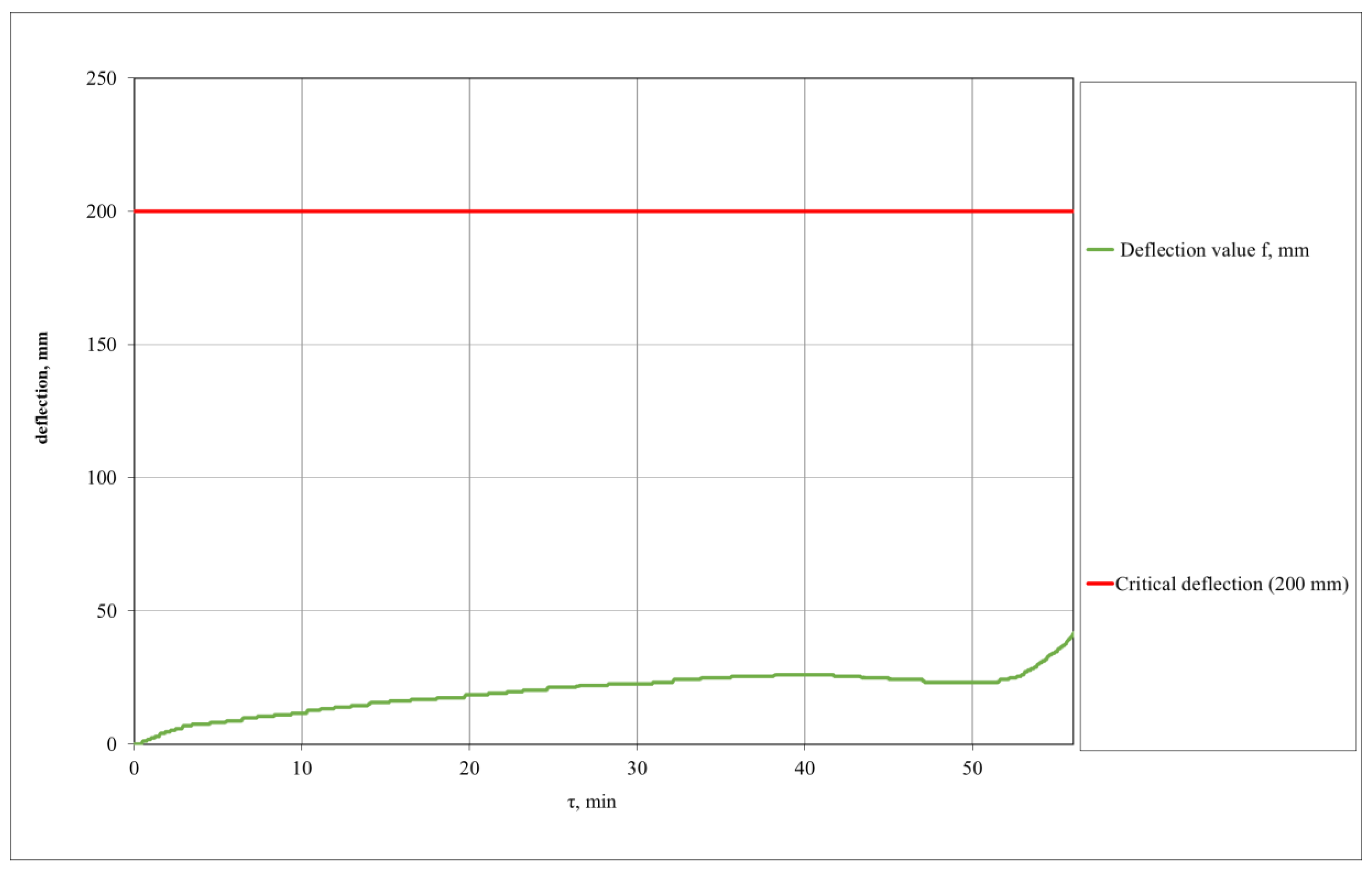
3.2. Aluminium Orthotropic Deck

Figure 17 shows the aluminium orthotropic deck before testing.
The ultimate limit state of the aluminium orthotropic deck was reached in 54 min (caused by burning on the unheated side). The test results from the thermoelectric transducers are shown in Figure 18 and Figure 19. The deformation of the aluminium orthotropic deck during testing is shown in Figure 20. Figure 21 demonstrates the aluminium orthotropic deck after testing.

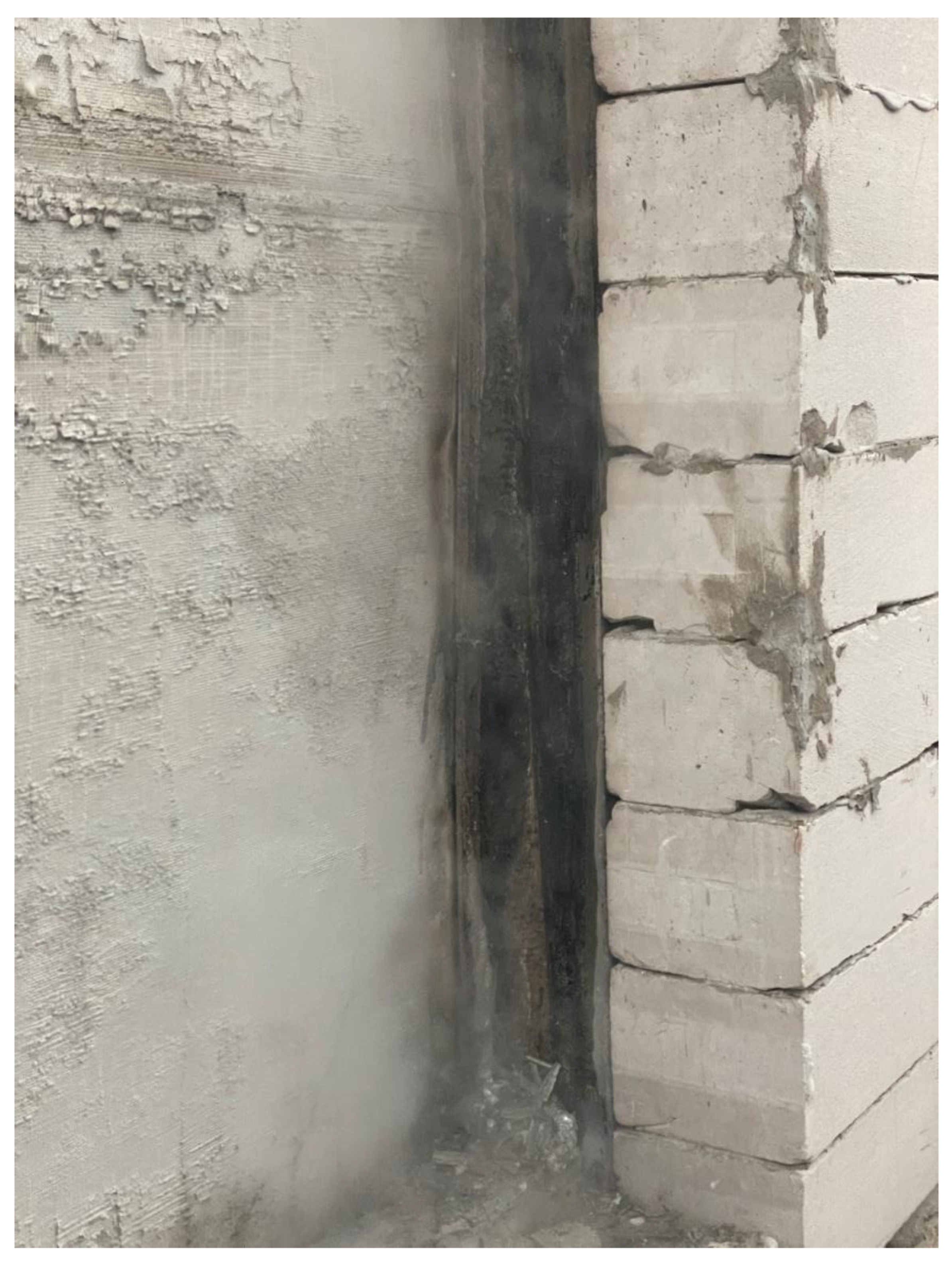
3.3. Aluminium Columns of Different Sections

Figure 22 presents the overview of the aluminium column ready for testing.
The results from the tests on the aluminium columns are provided in Table 2.
Figure 23 shows the overview of the aluminium column after testing.

4. Discussion

The data obtained from testing the attachment units with aluminium elements, aluminium orthotropic decks and aluminium columns can be the basis for a detailed analysis aimed at identifying the criteria with a significant impact on the stability of structures with aluminium that are exposed to fire.

4.1. Attachment Units of Translucent Panels Using the Aluminium Mullion and Transom System

An important distinction between the attachment unit of the mullion and transom system with a protective non-inflammable heat-insulating membrane and the attachment unit of the mullion and transom system covered with a fire-resistant cement slab is related to heat-insulating barriers in different parts of the structure. The attachment unit of the mullion and transom system with a protective non-inflammable heat-insulating membrane has it in the area between the aluminium and the protective casing to prevent heat transfer in case of fast aluminium heating. This caused a nearly complete melting of the aluminium mullions after testing (37 min after testing was started), which led to the destruction of the heat-insulating membrane and flame outburst (Figure 10). At the same time, it caused considerable overheating of the attachment elements that could potentially result in the collapse of the attachment unit of the mullion and transom system. The second type of the attachment unit of the mullion and transom system used a fire-resistant cement slab installed on the external side of transoms (from the heated side). This type of attachment unit reached the ultimate limit state in 62 min after testing was started and the mullions were only partially damaged. The observed result is due to the fact that aluminium has a high thermal conductivity. The presence of a heat-insulating layer between the protective box and aluminium accumulates heat in the aluminium without the possibility of its removal. In the absence of a protective membrane and the use of a fire-resistant cement board, aluminium slowly warms up, with the possibility of heat removal to the environment. Thus, the fire resistance of the attachment unit of the mullion and transom system covered with a fire-resistant cement slab to protect aluminium from high temperatures was 1.5 times higher.

4.2. The Aluminium Orthotropic Deck

Since the average melting temperature of aluminium is 660 °C, we have to analyse the reasons for the long-term stability of orthotropic decks in fire conditions. As was shown in the previously obtained results on the mullion and transom systems, the open use of aluminium leads to its rapid heating and destruction. Based on the received data and observations during testing, we can conclude that cavities in the aluminium orthotropic deck profile ensure equal temperature distribution and heat removal from aluminium structures (Figure 24 and Figure 25), which results in the long-term instability of the structure exposed to fire. Aluminium has high heat conductivity and the aluminium structure without air-blasted cavities could heat up to the critical temperature in 15–20 min, that is, three times faster than it happened in the studied aluminium orthotropic deck. Moreover, the asphalt coating used in orthotropic decks is a cooling agent providing heat removal from the structure, which caused burning on the unheated surface during testing.

4.3. Aluminium Columns of Different Sections

The results reveal that the most important parameter of the studied aluminium columns is the aluminium temperature in the internal cavities of aluminium columns, giving rise to deformation at the set load level. As shown earlier, the presence of heat dissipation in the air cavities of the structure leads to an increase in the fire resistance of the structure. After the deformation began, the ultimate limit state was reached within 1 min at low load (9 tons) and 30 s at high load (42 tons). The deformation onset temperatures versus load levels of the aluminium profile mullions of different sections are presented in Figure 26, Figure 27 and Figure 28.
Furthermore, in addition to the destruction caused by aluminium melting, there is an expansion of aluminium columns without load within 4–13 min after the testing was started. After testing. the aluminium columns were expanded by a maximum of 0.25%. During fire testing, the aluminium columns were subjected to deformation caused by heat exposure and loads. Sections and loads of aluminium columns determine the behaviour trends.
Based on the analysis of the mechanical changes in the aluminium columns and their warm-up, as well as an analysis of the behaviour of other types of aluminium structures given earlier, the following conclusions can be drawn: mechanical changes in aluminium columns depend on their warm-up properties and load levels. Aluminium columns without load are destroyed at 600–650 °C under gravity load. Taking into account the heat dissipation through the cavities of the structure, which was also shown in the case of assessing the fire resistance of orthotropic plates, the achievement of this limit state is slower than can be predicted for aluminium structures without heat dissipation.
Displacements of aluminium columns happen under low loads when aluminium is sufficiently heated and the heating is even along the wall thickness. In this case, its flexibility causes the collapse of the aluminium column along the section. If the aluminium column is not sufficiently warmed up but the loads are high, the column bends since only the external part of the section acquires the necessary flexibility due to heat exposure. However, heat removal in the internal cavity of the aluminium column can make the structure much more resistant to fire. It should be noted that the warming up of the aluminium free of air cavities, ensuring heat removal up to critical temperatures, can happen in 8–10 min. Thus, the fire resistance of the studied columns is increased by 1.5 times due to the air-permeable cavities.

5. Conclusions

We have studied the behaviour of aluminium structures exposed to high temperatures. Methods for testing attachment units of mullion and transom systems, aluminium orthotropic decks and aluminium columns were developed, taking into account the behaviour properties of selected structures—possible deformation and warm-up at high temperatures.
As part of the study, we registered the ultimate limit states of the tested structures and analysed the behaviour of aluminium structures exposed to fire.
The fire resistance versus fire protection method was identified for the attachment units of mullion and transom systems. We discovered that the structural fire protection of aluminium that ensures rapid heat transfer to attachment elements and creates conditions for heat removal is more efficient than the direct protection of attachment elements from heat coming from aluminium structural elements. In the first case, the fire resistance of the attachment unit of mullion and transom systems was 1.5 times higher.
We have assessed the warm-up of the aluminium orthotropic deck consisting of connected hollow profiles. It was discovered that hollow air-permeable profiles and asphalt coating acting as a cooling agent increase the fire resistance by three times due to heat removal from the structure.
We have determined the fire resistance of aluminium columns of different sections versus load levels. The results show that structures demonstrate high fire resistance at considerable loads as a result of heat removal from the aluminium in the hollow part of the structure. The fire resistance rating is 1.5 times higher in such structures compared to structures without air-permeable cavities.
Based on the research presented, we can conclude that the main technological solutions aimed at increasing the fire resistance of aluminium structures are hollow profiles in structures to provide air exchanges with cold sections of the structure, special cooling agents ensuring the cooling of the structure and heat removal to the atmosphere, and thermal barriers for the protection of aluminium structures.

Author Contributions

Conceptualization, F.A.P. and D.A.K.; methodology, F.A.P. and D.A.K.; software F.A.P.; validation, D.A.K.; formal analysis, F.A.P. and D.A.K.; investigation, F.A.P. and D.A.K.; resources, D.A.K.; data curation, D.A.K.; writing—original draft preparation, F.A.P.; writing—review and editing, F.A.P. and D.A.K.; visualization, F.A.P.; supervision, D.A.K.; project administration, D.A.K.; funding acquisition, D.A.K. All authors have read and agreed to the published version of the manuscript.

Funding

This research received no external funding.

Data Availability Statement

No new data were created or analyzed in this study. Data sharing is not applicable to this article.

Conflicts of Interest

The authors declare no conflict of interest.

References

  1. Aidarov, S.; Tošić, N.; Fuente, A. A limit state design approach for hybrid reinforced concrete column-supported flat slabs. Struct. Concr. 2022, 23, 3444–3464. [Google Scholar] [CrossRef]
  2. Aidarov, S.; Nogales, A.; Reynvart, I.; Tošić, N.; de la Fuente, A. Effects of low temperatures on flexural strength of macro-synthetic fiber reinforced concrete: Experimental and numerical investigation. Materials 2022, 15, 1153. [Google Scholar] [CrossRef]
  3. Goremikins, V.; Rocens, K.; Serdjuks, D. Decreasing displacements of prestressed suspension bridge. J. Civ. Eng. Manag. 2012, 18, 858–866. [Google Scholar] [CrossRef]
  4. Zehfuß, J.; Sander, L.; Schaumann, P.; Weisheim, W. Thermal material properties of fire protection materials for natural fire scenarios. Bautechnik 2018, 95, 535–546. [Google Scholar] [CrossRef]
  5. Mahmud, H.M.I.; Mandal, A.; Nag, S.; Moinuddin, K.A.M. Performance of fire protective coatings on structural steel member exposed to high temperature. J. Struct. Fire 2021, 12, 193–211. [Google Scholar]
  6. Jiang, S.; Wu, H. An experimental investigation on the fire resistance of the integrated envelope-fire protection material for steel buildings. Prog. Steel Build. Struct. 2021, 23, 77–84. [Google Scholar] [CrossRef]
  7. Gravit, M.V.; Dmitriev, I.I. Numerical modeling of basalt roll fire-protection for light steel thin-walled structures. Mag. Civ. Eng. 2022, 112, 11215. [Google Scholar] [CrossRef]
  8. Gravit, M.; Shabunina, D.; Antonov, S.; Danilov, A. Thermal characteristics of fireproof plaster compositions in exposure to various regimes of fire. Buildings 2022, 12, 630. [Google Scholar] [CrossRef]
  9. Galyamichev, A.; Gerasimova, E.; Egorov, D.; Serdjuks, D.; Grossman, A.; Lysenko, D. Bearing capacity of riveted connections of mineral wool sandwich panels. Mag. Civ. Eng. 2022, 112, 11202. [Google Scholar] [CrossRef]
  10. Zdanchuk, E.; Nikitina, O.; Galyamichev, A.; Serdjuks, D. Influence of protrusions on building façade on the distribution of peak wind loads. Lect. Notes Netw. Syst. 2022, 403, 1390–1398. [Google Scholar] [CrossRef]
  11. Hirkovskis, A.; Serdjuks, D.; Goremikins, V.; Pakrastins, L.; Vatin, N.I. Behaviour analysis of load-bearing aluminium members. Mag. Civ. Eng. 2015, 57, 86–96. [Google Scholar] [CrossRef] [Green Version]
  12. Korgin, A.V. Calculation of endurance of bridge structures and aluminium alloys. Build. Sci. Educ. 2022, 12, 31–49. [Google Scholar] [CrossRef]
  13. Korgin, A.V.; Yermakov, L.Z.; Kilani, Z. Including orthotropic deck plates into aluminium alloy bearing bridge structures. Newsl. Mosc. State Univ. Civ. Eng. 2022, 17, 882–896. [Google Scholar] [CrossRef]
  14. Golova, T.A.; Zhukov, A.D. Efficiency of using aluminium alloy window units for nuclear power plant buildings—Relevant challenges and development paths for power industry, engineering and technologies. In Proceedings of the VIII International Scientific and Practical Conference, Stockholm, Sweden, 15–18 November 2022; pp. 356–361. [Google Scholar]
  15. Sędłak, B.; Sulik, P.; Garbacz, A. Scale effect in the evaluation of the fire resistance of glazed partitions. J. Build. Eng. 2022, 49, 104–108. [Google Scholar] [CrossRef]
  16. Sędłak, B.; Sulik, P. The impact of reinforcing profiles on the fire resistance of aluminium glazed partitions Part 1. Builder 2020, 280, 25–27. [Google Scholar] [CrossRef]
  17. Langhelle, N.K.; Amdahl, J. Experimental and numerical analysis of aluminium columns subjected to fire. In Proceedings of the Eleventh International Offshore and Polar Engineering Conference, Stavanger, Norway, 17–22 June 2001; Volume 4, pp. 406–413. [Google Scholar]
  18. Maljaars, J.; Soetens, F.; Snijder, H.H. Local buckling of aluminium structures exposed to fire. Part 1: Tests. Thin-Walled Struct. 2009, 47, 1404–1417. [Google Scholar] [CrossRef]
  19. Faggiano, B.; Mazzolani, M.F.; Matteis, G.; Landolfo, R. On the fire resistance of aluminium alloy structures. In Improvement of Buildings’ Structural Quality by New Technologies; CRC Press: Boca Raton, FL, USA, 2005; pp. 267–275. [Google Scholar] [CrossRef]
  20. Zakharov, V.V.; Rostova, T.D.; Fisenko, I.A. High-strength weldable corrosion-resistant aluminum alloy for bearing building structures. Met. Sci. Heat Treat. 2005, 47, 377–382. [Google Scholar] [CrossRef]
  21. Pancheti, J.; Mahendran, M.; Steau, E. Fire resistance of external LSF walls with corrugated steel cladding. J. Constr. Steel Res. 2021, 188, 107008. [Google Scholar] [CrossRef]
  22. Zakharov, V.V.; Rostova, T.D. High-strength weldable alloy 1970 based on the Al-Zn-Mg system. Met. Sci. Heat Treat. 2005, 47, 131–138. [Google Scholar] [CrossRef]
  23. Luzik, S.J. Protection of aluminum overcast constructions against fire. Fire Technol. 1998, 24, 227–244. [Google Scholar] [CrossRef]
  24. Maljaars, J.; Soetens, F.; Katgerman, L. Constitutive model for aluminum alloys exposed to fire conditions. Metall. Mater. Trans. A 2008, 39, 778–789. [Google Scholar] [CrossRef] [Green Version]
  25. Maljaars, J.; Twilt, L.; Fellinger, J.H.H.; Snijder, H.H. Aluminium structures exposed to fire conditions—An overview. Heron 2010, 55, 85–122. [Google Scholar]
  26. Maljaars, J.; Matteis, G. Structural response of aluminium T-stub connections at elevated temperatures and fire. Key Eng. Mater. 2016, 710, 127–136. [Google Scholar] [CrossRef]
  27. Summers, P.T.; Chen, Y.; Rippe, C.M.; Allen, B.; Mouritz, A.P.; Case, S.W.; Lattimer, B.Y. Overview of aluminum alloy mechanical properties during and after fires. Fire Sci. Rev. 2015, 4, 3. [Google Scholar] [CrossRef] [Green Version]
  28. Suzuki, J.; Ohmiya, Y.; Wakamatsu, T.; Haradaz, K.; Yusa, S.; Kohno, M. Evaluation of fire resistance of aluminum alloy members. Fire Sci. Technol. 2005, 24, 237–255. [Google Scholar] [CrossRef] [Green Version]
  29. Davor, S.; Ivan, C.; Maljaars, J. Behaviour of aluminium structures in fire—A review. In Proceedings of the 4th International Conference—Applications of Structural Fire Engineering (ASFE 2015), Dubrovnik, Croatia, 15–16 October 2015. [Google Scholar] [CrossRef] [Green Version]
  30. Sun, Y.; Fu, Z.; Song, Y.; Xia, J. Cross-sectional behavior of aluminum alloy channel section stub columns after exposure to fire. J. Struct. Eng. 2023, 149, 04023085. [Google Scholar] [CrossRef]
  31. Gravit, M.; Golub, E.; Klementev, B.; Dmitriev, I. Fire protective glass fiber reinforced concrete plates for steel structures under different types of fire bxposure. Buildings 2021, 11, 187. [Google Scholar] [CrossRef]
  32. Winter, A.; Butler, F. Passive fire protection for aluminum structures. Nav. Eng. J. 2009, 87, 59–66. [Google Scholar] [CrossRef]
Figure 1. Cable-stayed bridge over the Moskva River.
Buildings 13 01669 g001
Figure 2. Research flowchart.
Buildings 13 01669 g002
Figure 3. Layout for testing attachment units: 1—testing furnace; 2—protective casing of mullion and transom system; 3—mullion and transom system with aluminium; 4—simulation of structure filling; T1–T6—thermoelectric transducers.
Buildings 13 01669 g003
Figure 4. The heating and load schemes for an aluminium orthotropic deck: P—pressure; Q—heat exposure.
Buildings 13 01669 g004
Figure 5. Layout of thermoelectric transducers on the unheated surface of the tested orthotropic deck (T1, T2, T3, T4 and T5).
Buildings 13 01669 g005
Figure 6. Layout of thermoelectric transducers on the walls of the tested orthotropic deck profile (T6, T7 and T8).
Buildings 13 01669 g006
Figure 7. Layout of thermoelectric transducers (T1, T2, T3, T4, T5, T6 and T7) on the aluminium column: 1—aluminium column; 2—reinforced concrete support; 3—support steel plate; 4—auxiliary fastening pad; 5—support attachment; 6—fastening element ensuring stability of the aluminium column; P—pressure.
Buildings 13 01669 g007
Figure 8. The unheated side of the attachment unit of the mullion and transom system before testing.
Buildings 13 01669 g008
Figure 9. The heated side of the attachment unit of the mullion and transom system with a protective non-inflammable heat-insulating membrane before testing.
Buildings 13 01669 g009
Figure 10. Temperatures measured using thermocouples T1, T2, T3, T4, T5 and T6 placed on the unheated surface of the attachment unit of the mullion and transom system with a protective non-inflammable heat-insulating membrane versus heat exposure time.
Buildings 13 01669 g010
Figure 11. Deflection of the attachment elements of the attachment unit of the mullion and transom system with a protective non-inflammable heat-insulating membrane versus heat exposure time.
Buildings 13 01669 g011
Figure 12. The state of the mullion and transom system after testing the attachment unit of the mullion and transom system with a protective non-inflammable heat-insulating membrane.
Buildings 13 01669 g012
Figure 13. The attachment unit of the mullion and transom system covered with a fire-resistant cement slab before testing.
Buildings 13 01669 g013
Figure 14. Temperatures measured using thermocouples T1, T2, T3, T4, T5 and T6 placed on the unheated surface of the attachment unit of the mullion and transom system covered with a fire-resistant cement slab versus heat exposure time.
Buildings 13 01669 g014
Figure 15. Deflection of the attachment unit of the mullion and transom system covered with a fire-resistant cement slab versus heat exposure time.
Buildings 13 01669 g015
Figure 16. The state of the attachment unit of the mullion and transom system covered with a fire-resistant cement slab after heat exposure during testing.
Buildings 13 01669 g016
Figure 17. The aluminium orthotropic deck before testing.
Buildings 13 01669 g017
Figure 18. Temperatures measured using thermocouples T1, T2, T3, T4 and T5 placed on the unheated surface of the aluminium orthotropic deck versus heat exposure time.
Buildings 13 01669 g018
Figure 19. Temperatures measured using thermocouples T6, T7 and T8 placed on the walls of the aluminium orthotropic deck profile versus heat exposure time.
Buildings 13 01669 g019
Figure 20. Deflection of the aluminium orthotropic deck versus heat exposure time.
Buildings 13 01669 g020
Figure 21. The aluminium orthotropic deck after testing.
Buildings 13 01669 g021
Figure 22. Aluminium column No. 2.4.3 ready for testing.
Buildings 13 01669 g022
Figure 23. The aluminium column No. 2.4.3 after heat exposure.
Buildings 13 01669 g023
Figure 24. Equal temperature distribution in the aluminium orthotropic deck section exposed to fire: Q—heat exposure.
Buildings 13 01669 g024
Figure 25. Heat removal from the cavities of the aluminium orthotropic deck: Q—heat exposure.
Buildings 13 01669 g025
Figure 26. Deformation onset temperatures versus load levels of 300 mm × 150 mm × 15 mm aluminium rectangular section columns.
Buildings 13 01669 g026
Figure 27. Deformation onset temperatures versus load levels of 200 mm × 120 mm × 12 mm aluminium rectangular section columns.
Buildings 13 01669 g027
Figure 28. Deformation onset temperatures versus load levels of 160 mm × 100 mm × 8 mm aluminium rectangular section columns.
Buildings 13 01669 g028
Table 1. List of the tested columns.
No. of Aluminium ColumnsElement Section, mmLoad,
Tonne
Element Length,
m
1.1.1
1.1.2
300 × 150 × 1520.02.50
1.2.1
1.2.2
1.2.3
300 × 150 × 1540.02.50
1.3.1
1.3.2
300 × 150 × 1560.02.50
1.4.1
1.4.2
1.4.3
300 × 150 × 1576.02.50
2.1.1
2.1.2
200 × 120 × 120.02.00
2.2.1
2.2.2
200 × 120 × 1211.02.00
2.3.1
2.3.2
200 × 120 × 1222.02.00
2.4.1
2.4.2
2.4.3
200 × 120 × 1242.02.00
3.1.1
3.1.2
160 × 100 × 80.02.00
3.2.1
3.2.2
160 × 100 × 89.02.00
3.3.1
3.3.2
3.3.3
160 × 100 × 813.02.00
3.4.1
3.4.2
160 × 100 × 816.02.00
Table 2. The experimental results from the test on the aluminium columns.
No. of Aluminium ColumnsDeformation Onset Time, minDeformation Onset Temperature, °CTime for Reaching the Ultimate Limit State Related to the Loss of the Bearing Capacity (R), minTemperature of Aluminium Column When the Ultimate Limit State Related to the Loss of the Bearing Capacity (R) Is Reached or the Column Is Destroyed, °CTime When T = 400 °C Is Reached, minTime of Destruction, min
1.1.1 18:4035518:50370
1.1.216:4536017:20 370
1.2.116:3030516:40 310
1.2.216:4031017:05315
1.2.316:3031517:00 320
1.3.115:4529516:05 305
1.3.215:5029516:10 305
1.4.116:1028016:35 295
1.4.214:1525014:40 255
1.4.315:4027015:50 280
2.1.1 60016:4031:00
2.1.2 60016:30
2.2.117:2042019:1544016:30
2.2.217:4542019:5045016:50
2.3.115:4537016:15380
2.3.216:1036016:45 385
2.4.113:3032014:00 330
2.4.214:0035014:20 360
2.4.313:1532513:40 340
3.1.1 67513:5028:50
3.1.2 67513:3028:20
3.2.113:2039514:1042013:40
3.2.213:1039514:0042513:20
3.3.111:3036012:00 375
3.3.212:0037512:30 385
3.3.311:5037512:10 385
3.4.111:2035011:50 375
3.4.211:0034511:30 360
Disclaimer/Publisher’s Note: The statements, opinions and data contained in all publications are solely those of the individual author(s) and contributor(s) and not of MDPI and/or the editor(s). MDPI and/or the editor(s) disclaim responsibility for any injury to people or property resulting from any ideas, methods, instructions or products referred to in the content.

