Article

Experimental Study of the Concrete Cracking Behavior of an Immersed Tunnel under Fire

1
State Key Laboratory of Subtropical Building Science, South China University of Technology, Guangzhou 510641, China
2
Guangdong Province Enterprise Key Laboratory of Materials and Elements Fire Testing Technology, Guangzhou Building Material Institute Limited Company, Guangzhou 510663, China
3
Guangzhou Metro Group Co., Ltd., Guangzhou 510000, China
*
Author to whom correspondence should be addressed.
Buildings 2023, 13(6), 1412; https://doi.org/10.3390/buildings13061412
Submission received: 4 May 2023 / Revised: 22 May 2023 / Accepted: 27 May 2023 / Published: 30 May 2023
(This article belongs to the Collection Buildings and Fire Safety)

Abstract

:
This study investigates the impact of fire on the cracking behavior of immersed tunnels. A reduced-scale (1:5) model of an immersed tunnel was constructed to conduct fire tests in both traffic tubes using the HCinc curve as the applied fire. Temperature field changes were carefully monitored during the test by thermocouples and infrared thermography on the outer surface of the tunnel’s ceiling. The continuous temperature field and temperature changes in the concrete cracks were recorded by infrared thermography. By integrating the temperature field distribution in concrete and the behavior of concrete cracking, an analysis of the depth of concrete cracking in the immersed tunnel under fire was conducted. The concrete cracks exceeded 150 mm at 95 min of the fire test. The results indicate that the inner concrete exposed to fire undergoes thermal expansion, leading to tensile cracking of the outer concrete. Additionally, the fire-exposed surface of the tunnel is vulnerable to cracking due to a temperature decrease. Thus, the design of fire resistance of immersed tunnels should take into consideration the potential for concrete cracking caused by thermal strain.

1. Introduction

Tunnel engineering has gained popularity and development in recent years, but it also poses several challenges, one of which is fire. With the increasing number and speed of automobiles, tunnel fires caused by accidents have become significant risk factors affecting tunnel safety. In China, statistics indicate that the probability of tunnel fire is 10–17 times per 100 million km of a car [1]. Fires in immersed tunnels, which are buried in the seabed, pose unique challenges due to their location in a seawater environment [2], because water seepage is a significant threat to the safety of personnel and property within immersed tunnels. During the construction of the Seikan submarine tunnel in Japan, 33 people died due to water seepage [3]. The seepage incidents in the Seikan submarine tunnel were caused by the progressive enlargement of rock fractures due to the hydraulic action of seawater. The first incident resulted in the influx of 11 t seawater per minute into the tunnel, while the second incident increased the flow rate to 70 t seawater per minute. Additionally, during the Seikan submarine tunnel in service, seepage incidents were also reported. They were caused by a crack in one of the cement panels lining the tunnel walls, which was probably due to the expansion and contraction of the tunnel structure caused by changing temperatures. Immersed tunnels are in the seabed and, consequently, have a high moisture content in their concrete. However, concrete with a high moisture content is prone to spalling and cracking under high temperatures [4]. Moreover, in the event of a fire in an immersed tunnel, the internal thermal expansion of the tunnel can easily lead to tensile cracking of the outer concrete. Al-Bashiti et al. [5] utilized the artificial intelligence method to investigate key factors that affect concrete spalling under fire, such as critical factors being moisture content, heating rate, and highest temperature. These factors of the immersed tunnel are usually in disadvantageous situations. Khoury [6] revealed that the permeability of concrete is a factor that influences concrete spalling under fire. However, for the immersed tunnel design to prevent water leakage, usually low-permeability concrete is employed, which is also disadvantageous for the immersed tunnel.
Wang and Li [7] conducted a simulation study using ANSYS to investigate the impact of fire on the structural behavior of immersed tunnels. The results of the simulation showed that the maximum deformation of the immersed tunnel under fire was 3.6 mm, while some positions of the tunnel were at risk of cracking and crushing. Previous research [8,9] analyzed the bearing capacity of the immersed tunnel under room temperature and found that the safety factor of the bearing capacity was high. The ultimate bearing capacity of the immersed tunnel under normal service loads was controlled by the width of the concrete cracks. Therefore, concrete cracking is a critical factor affecting the structural safety of immersed tunnels. Water seepage is a great threat to an immersed tunnel. Even without through-cracks, concrete cracking can expose the rebars of an immersed tunnel to seawater, accelerate the corrosion of rebars, and reduce the service life of the immersed tunnel.
However, the effect of fire on the cracking behavior of immersed tunnels has not been extensively studied. Previous research has mainly focused on the spread of fire smoke in an immersed tunnel [10] and the temperature distribution in an immersed tunnel [11]. Insufficient attention has been paid to the damage caused by concrete cracking in immersed tunnels under fire. Fire tests conducted on underground structures have shown severe cracking and through-cracks in concrete structures [12,13]. Ring et al. [14] observed through-cracks during fire tests on underground structures with a thickness of 400 mm, and concrete cracking occurred before the failure of the structures.
To ensure the safety of immersed tunnels in the event of a fire, it is critical to understand their cracking behavior. This study investigates the cracking behavior of an immersed tunnel using the Hong Kong Zhuhai Macao Bridge as a prototype. A 1:5 reduced-scale model was constructed to conduct fire tests and monitor the tunnel’s cracking behavior using an infrared thermal imager. This approach overcomes the limitations of traditional crack detection technologies in measuring concrete crack depth of the immersed tunnel under fire. By combining the principles of water migration in concrete at high temperatures with temperature distribution in concrete, the cracking depth of concrete was accurately deduced. This research sheds light on the behavior of immersed tunnels under fire and provides valuable insights for the fire resistance of immersed tunnels.

2. Test Setup

2.1. The Reduced-Scale Model

The standard element length of an immersed tunnel is 180 m, which consists of 8 segments, each with a length of 22.5 m. These segments are connected through waterproof joints to form an element. Due to the width of the immersed tunnel section being 37.95 m and the height being 11.4 m, full-scale fire tests are difficult to conduct. Therefore, a reduced-scale model of the standard segment was built, following the reduced-scale tests of the immersed tunnel’s shear keys [15,16]. The scale factor of 1:5 was used, which was based on the limitations of the test site, loading equipment, and heating system. The prototype and reduced-scale model of the immersed tunnel are shown in Figure 1. The dimensions of the reduced-scale model were 5.8 m in length, 7.59 m in width, and 2.28 m in height. Except for the midwall (160 mm), the thickness of all other components of the immersed tunnel was 300 mm. For detailed information on the similarity coefficients of models, please refer to previous work [2]. The structure and rebar forms of the immersed tunnel are illustrated in Figure 2. The same materials (C50 and HRB400) as the prototype were used to build the reduced-scale model. The granite gravel used in this study had a continuous gradation, with particle sizes ranging from 5 to 20 mm (with a mass ratio of 3:7 between particles of 5–10 mm and 10–20 mm), as shown in Table 1. Before the fire test was carried out, no pre-existing shrinkage cracks were detected on the surface of the immersed tunnel.
To simulate hydrocarbon fires that may arise from traffic accidents in an immersed tunnel, a fire test was conducted. The temperature curve for the test was defined using the HCinc curve, which characterized the temperature change resulting from the combustion of chemical transport tanks, gasoline tanks, and diesel tanks in tunnels. To simulate more severe fires, the HC curve can be multiplied by the coefficient β = 1300/1080, resulting in the HCinc curve. The temperature–time relationship for the HC curve is represented by Equation (1).
T g T 0 = 1080 ( 1 0.325 e 0.167 t 0.765 e 2.5 t )
where Tg is the average temperature at the time t of fire (°C); t is the fire duration (min); T0 is the initial temperature (°C).
The heating system utilized diesel as fuel, and flame was sprayed by burners to provide heat in the immersed tunnel. The fire test furnace was designed based on the heat balance method [17]. According to the principle of energy conservation, the fire test furnace was in thermal equilibrium, where the heat generated by diesel combustion was equal to the sum of the heat absorbed by the immersed tunnel and the heat taken away by the high-temperature smoke discharged from the furnace. To create a closed space within the immersed tunnel, walls were constructed at both ends of the tunnel. Four flues were built at the bottom of the tunnel to enable the high-temperature smoke to enter the flues through the vents on the floor of the tunnel. The high-temperature smoke could not be discharged directly through the induced draft fan. Before entering the fan, the smoke was cooled by the water spray cooling system and filtered to prevent environmental pollution. The fire test furnace is illustrated in Figure 3, while the fire test scene of the immersed tunnel is depicted in Figure 4.
Temperature is a critical factor that leads to structural damage during fire tests conducted in tunnels. The furnace temperature and the temperature field of the tunnel need to record. The furnace temperature was monitored via twelve type-S thermocouples that were placed within the test furnace. The temperature distribution of the tunnel was determined using type-K thermocouples that were embedded within the concrete. Thermocouples can only be used to measure the temperature of discrete points of the structure. If the concrete does not crack, the temperature at discrete points can reflect the overall temperature field of the structure. Cracking in concrete induces temperature fluctuations at the fracture site. Therefore, precise temperature monitoring at the fracture site becomes unattainable if the crack formation is not aligned precisely with the thermocouples.
When the concrete develops cracks due to fire, moisture inside the concrete migrates from areas with higher temperature to those with lower temperature through these cracks. The water inside the concrete will overflow from cracks on the unexposed side of fire. As the water comes from a high-temperature area, it leads to an elevated temperature at the crack location. If the concrete forms through-cracks, high-temperature smoke and gas of the fire will also escape through the cracks, causing a significant rise in temperature at the crack location. Hence, the analysis of concrete cracking under fire requires detailed monitoring and assessment of various parameters, such as concrete crack temperature, overflowing water and vapor temperature within the cracks, surrounding concrete temperature, and fire temperature. In this study, the continuous temperature field of the tunnel ceiling was monitored using infrared thermography, while concurrently recording the temperature of concrete, concrete cracks, water, and vapor overflowing from the cracks during the fire test.

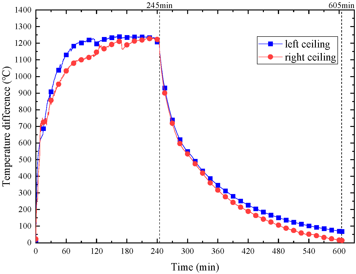
2.2. Infrared Thermography Recorded the Temperature of Ceiling

Infrared thermography operates by utilizing infrared radiation to measure the surface temperature of an object or material. The infrared light signal emitted by the object is converted into an electrical signal, yielding the spatial distribution of the surface temperature of the object through the output signal of the imaging device. Following appropriate processing, a thermal image corresponding to the surface temperature field of the object can be obtained [18]. The spatial distribution of the surface temperature of the object is obtained through the output signal of the imaging device. Subsequent software processing enables the acquisition of a thermal image corresponding to the surface temperature field of the object. In instances where concrete specimens exhibit varying degrees of damage, variations in the surface temperature and infrared thermal image characteristics are primarily influenced by the thermal diffusivity α of the concrete under identical conditions. The accurate measurement of the infrared radiation from the surface of an object is instrumental in determining its surface temperature, as well as inferring its material properties, internal structure, and surface state based on the intrinsic relationship among infrared radiation, surface temperature, and material properties.
Throughout the fire test, infrared thermography was utilized to record the temperature of the outer surface of the tunnel ceiling. As the fire progressed, water and vapor emanated from concrete cracks and covered the concrete surface. As a result, the focus of the infrared thermography observations shifted from the concrete surface to the water, which overflowed from the cracks and progressively covered the outer surface of the ceiling. Therefore, the parameters of the infrared thermography needed to be adjusted, specifically the emissivity of water and concrete, which is the parameter related to the measured object. In the present study, the emissivity in the infrared thermography was adjusted when the crack of the ceiling was filled with water, as the cracking of submerged tunnels during fire was primary research object. Figure 5 illustrates the cracks and water on the ceiling. At 35 min, most of the cracks on the ceiling were filled with water, and the emissivity of concrete (0.94) in infrared thermography was adjusted to the emissivity of water (0.957) at that moment. At 50 min, most areas of the ceiling surface had been covered by water.
Notably, the process of the concrete surface becoming submerged in water was gradual. It was necessary to select an appropriate time to change the emissivity in the infrared thermography during the fire test. Specifically, the emissivity of the concrete was adjusted to that of water at the point when the ceiling surface was progressively covered by water.

3. Analysis of Fire Test Results

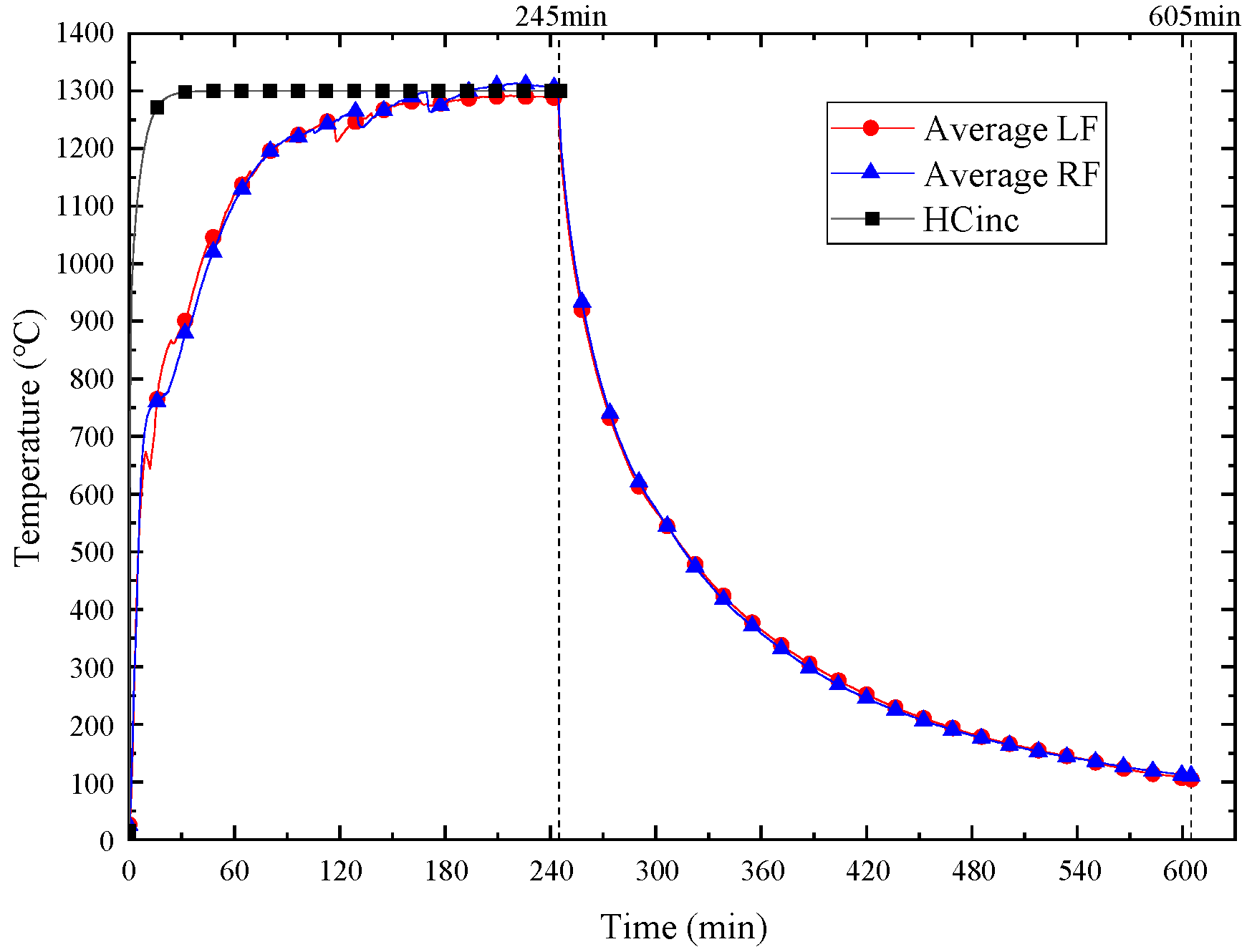
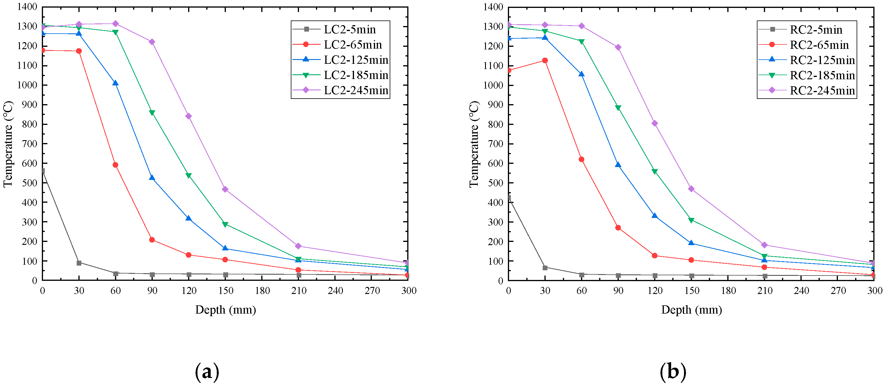
3.1. Temperature Field of the Immersed Tunnel

Following the application of the mechanical loads on the immersed tunnel, the loads were maintained for 12 h to ensure that the deformation and settlement of the tunnel were stabilized. Subsequently, the fire test was conducted on both tubes of the tunnel, while the mechanical loads were sustained throughout the test. The fire test comprised two phases, namely heating and cooling, with the former lasting 245 min and the latter 360 min. The temperature curve of the fire test furnace is depicted in Figure 6. At the early stage of the fire test, the furnace temperature rise rate was lower than the HCinc curve, owing to the high moisture content in the concrete, which led to the evaporation of the moisture, thereby absorbing a significant amount of heat. Furthermore, the burners could not achieve maximum power due to the insufficient combustion of diesel, which also contributed to the low furnace temperature rise rate. As the temperature heightened, the moisture within the concrete began to evanesce, thereby augmenting the thermal efficiency of the burners. Subsequently, in the later stage of the fire test, the furnace temperature approached the HCinc curve and ultimately attained a temperature of 1300 °C.
To determine the temperature distribution within the tunnel ceiling, type-K thermocouples embedded in concrete, as exemplified in Figure 7, were utilized. The temperature readings from two thermocouples situated in proximity to the fire-exposed surface indicated close agreement with the furnace temperature. Concrete spalling led to the exposure of the embedded thermocouples to open flames, causing the devices to measure the fire temperature rather than the concrete temperature. The ceiling concrete encountered spalling to a depth of 50 mm, giving rise to a remaining thickness of 250 mm. Due to the low thermal conductivity of concrete, a considerable temperature gradient was established within the material. The temperature variations along the depth of the ceiling are presented in Figure 8. During the fire test, the temperature discrepancy between the external and internal surfaces of the ceiling exceeded 1200 °C as depicted in Figure 9. Moreover, the temperature gradient in proximity to the fire-exposed surface reached 13.0 °C/mm.
The large temperature gradient between the inner and outer surfaces of the ceiling indicated the challenge of coordinating thermal strain within the ceiling. Specifically, the inner surface experienced high temperatures and significant thermal strain, while the outer surface remained cool and underwent minimal thermal strain. The thermal expansion of the inner surface was limited by the outer concrete, leading to compression of the former and tension in the latter. When the temperature difference between the internal and external surfaces of the immersed tunnel crossed a certain threshold, the external surface received tensile stress that exceeded the ultimate tensile strength of the concrete, instigating the formation of cracks. The depiction of the mechanism explaining concrete cracking due to uncoordinated thermal strain is presented in Figure 10.
During the fire test, the maximum deformation of the tunnel was found to be merely 14.5 mm after 245 min of heating. Notably, the deformation direction of the tunnel was observed to be opposite to that of the mechanical loads. These results suggest that the bearing capacity of the immersed tunnel under fire was adequate, further avoiding significant deformation due to the intense heat. However, despite the structural integrity of the tunnel, the outer surface still exhibited severe cracking during the fire test (Figure 11). As previously analyzed, uncoordinated thermal strain primarily caused this effect, leading to severe cracking of the immersed tunnel even with sufficient bearing capacity. Notably, the structural characteristics of the immersed tunnel render it susceptible to tensile cracking induced by thermal expansion inside the tunnel under fire. As these tunnels are frequently located deep beneath the ocean, severe concrete cracking may result in seawater seepage into the tunnel, triggering a catastrophic disaster. Therefore, even when the bearing capacity of the immersed tunnel is satisfactory under fire, ensuring the safety of the tunnel remains a challenging task. Consequently, it is crucial to consider the impact of concrete cracking on the safety of the immersed tunnel.
Thermocouples are commonly used to measure temperatures in building fires, but their ability to accurately capture the continuous temperature field of a tunnel is limited. In contrast, infrared thermography can effectively measure the continuous temperature field of the tunnel surface. In this study, the outer surface temperature of the tunnel was monitored using infrared thermography during the fire test, as shown in Figure 12. It is important to note that the lens angle of the infrared thermography was narrow; therefore, not all areas of the ceiling could be monitored. An analysis of Figure 12 reveals that at 100 min, the temperature in the cracked area of the ceiling (approximately one third of the tunnel’s cross-section) increased significantly, while the temperature in the uncracked area of the ceiling remained notably lower. This finding is consistent with the macroscopic test phenomenon of the outer surface of the tunnel (see Figure 5), where irregularly distributed cracks were observed, and boiling water and vapor overflowed from the concrete cracks. The high temperature at the concrete cracks is believed to have resulted from water and vapor in the high-temperature areas of the concrete migrating to the surface through the cracks, subsequently heating the concrete at the cracks. A frame-by-frame analysis of the infrared image, combined with macroscopic observations of the concrete cracking during the fire test, enabled the identification of the distribution of the primary cracks on the outer surface of the immersed tunnel, as presented in Figure 13. These findings highlight the potential of infrared thermography in accurately measuring the continuous temperature field of a tunnel surface during a fire test and its ability to aid in the identification of crack distribution and associated phenomena.

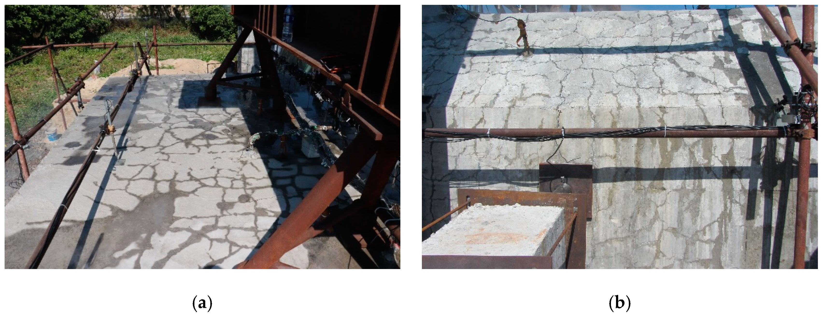
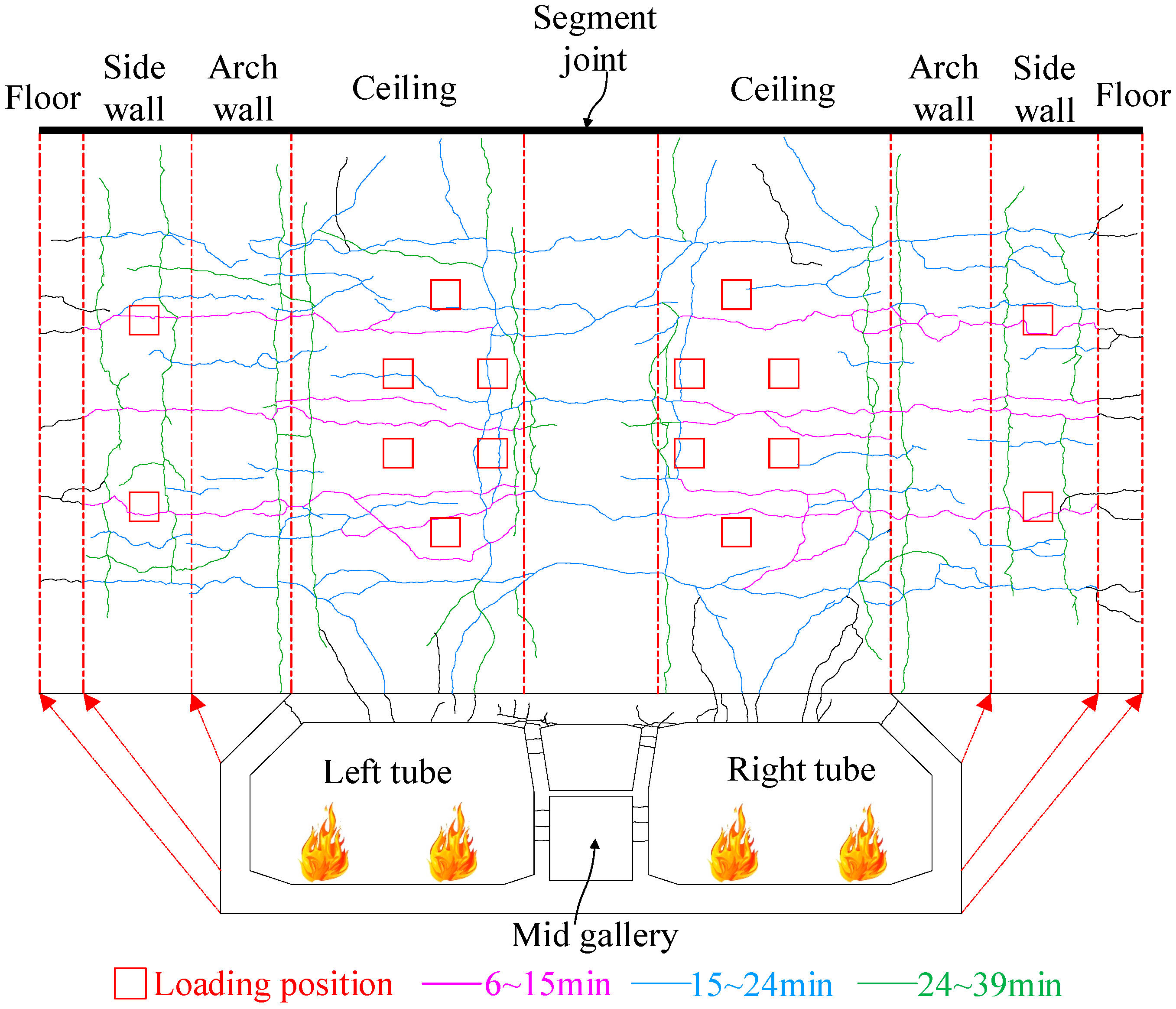
3.2. Analysis of Cracks Depth

In the fire test, the migration of moisture in concrete from high-temperature to low-temperature areas is predominantly propelled by the vapor pressure within the high-temperature region. When exposed to fire, moisture in concrete undergoes a phase change and transforms into vapor. The expansion of vapor volume leads to an increase in vapor pressure within the concrete, causing high-pressure vapor to diffuse toward the low-pressure area (low-temperature area). As the vapor diffuses, its temperature gradually decreases, resulting in condensation into liquid water, which continues to accumulate in the low-temperature area. This phenomenon facilitates the diffusion of moisture from the high-temperature area to the low-temperature area. The migration of moisture in concrete during a fire is a critical factor in understanding the behavior of concrete cracking under fire.
Stelzner et al. [19] investigated the behavior of moisture migration in concrete under high temperatures using CT scanning. Their findings revealed that moisture migration in concrete at 800 °C occurred at a very slow pace. Although the moisture content in the low-temperature region increased at high temperatures, the rate of increase was also slow. Li [20] reported that the mobility of liquid water in concrete could be disregarded based on their experimental results. It was concluded that liquid water could not move in concrete within a short time, except during the occurrence of cracks. The presence of cracks in concrete allowed the rapid migration of liquid water through them. The depth of concrete cracks can be ascertained by monitoring water and vapor discharging from the cracks situated on the fire-unexposed surface of the concrete during the fire.
In the fire test, the outer surface temperature of the ceiling, including the concrete surface temperature, as well as the temperature of water and vapor discharging from concrete cracks, was recorded via infrared thermography. The infrared images revealed that the temperature at the concrete cracks was higher, owing to the high temperature of water and vapor overflowing from the cracks. Figure 14 presents a comparison between the temperature of water and vapor at the cracks obtained from infrared images and the temperature of the concrete surface measured by the thermocouple. At 30 min, the temperature of water and vapor at the concrete cracks gradually rose, while the concrete surface temperature of the ceiling resembled the ambient temperature. At 60 min, the temperature of water and vapor at the concrete cracks elevated rapidly, reaching 82.8 °C in a short period and being sustained at a high temperature thereafter. The temperature variations of the ceiling surface monitored by infrared thermography were consistent with the macroscopic test phenomena detected on the outer surface of the ceiling. Specifically, at 27 min, the volume of water discharging from the concrete cracks on the ceiling steadily increased, as shown in Figure 5a, and at 58 min, boiling water vapor started to overflow from the cracks on the ceiling, as illustrated in Figure 5d.
As discussed previously, the migration of moisture in concrete over a short period can be neglected. However, water and vapor that quickly overflowed on the outer surface of the ceiling migrated inside the concrete through cracks. During the migration of water and vapor from high-temperature to low-temperature areas, they were cooled. In the initial stage of the fire test, the temperature of the concrete was low, the internal cracks were small, and the vapor pressure inside the concrete was not high. As a result, the migration of water and water vapor to the low-temperature area was relatively slow. A small amount of water vapor was rapidly cooled by concrete and condensed into liquid water. Consequently, only a small amount of liquid water overflowed from the concrete cracks, and the temperature did not increase significantly. Figure 5 and Figure 12 show the water overflow on the ceiling surface and the infrared image of the ceiling, respectively. With the progression of the fire test, the concrete temperature gradually increased. Under the influence of high temperatures, the moisture in the concrete vaporized rapidly, and the pressure inside the concrete increased rapidly. High-pressure vapor inside the concrete was released through cracks. At the time, the internal cracks in the concrete were relatively large, and the vapor pressure could propel the water and vapor in the concrete to quickly migrate to the low-temperature area through the cracks. Water and water vapor lost less heat during their rapid migration to the low-temperature area. Therefore, a significant amount of high-temperature water and vapor overflowed from the concrete cracks at the stage, as shown in Figure 15. At 95 min, boiling water and vapor overflowed from the concrete cracks, but the temperature monitored by infrared was 85.7 °C because the high-temperature water vapor was cooled by low-temperature water and concrete during its migration to the low-temperature area.
Under high temperatures, the migration of moisture in concrete can be neglected over a short period, and vapor only traverses a small distance. Cracks in the concrete facilitate the rapid migration of water and vapor. A schematic diagram of moisture migration was developed based on the mechanism of high-temperature moisture migration in concrete, as depicted in Figure 16. The temperature of water and vapor overflowing from cracks and the temperature field distribution in the concrete can assist in identifying the development of concrete cracks during fires. At 95 min, Figure 16 demonstrates the temperature distribution of the concrete and the temperature of the water and vapor spewing from the cracks. The temperature of the water and vapor within the cracks was 82.8 °C, while the temperature of the concrete’s outer surface was 30.0 °C. High-temperature water and vapor must have originated from the concrete area where the temperature exceeded 82.8 °C, indicating that the cracks must have expanded to the location where the temperature exceeded 82.8 °C in the concrete. Otherwise, the overflowing water and vapor would have been lower than 82.8 °C. The temperature field distribution in the concrete revealed that the depth of the crack had surpassed 150 mm at this time. Because boiling vapor discharged from the crack, the concrete temperature at a depth of 150 mm was 98.0 °C. Using this method, it was determined that, at 95 min, the cracks on the outer surface of the ceiling had penetrated 150 mm into the concrete. It should be acknowledged that the thermocouples were sparsely distributed within the concrete, and this method provides only an approximate estimation of the crack depth. The precision of the crack depth depends on the density of the thermocouples placed in the concrete. Given that the depth of the ceiling was 300 mm, the exposure of a crack depth exceeding 150 mm poses significant risks to immersed tunnels, placing them in danger of rebar corrosion and water seepage.
In an immersed tunnel, fire can raise the temperature inside the tunnel, causing significant thermal strain and outward expansion. This expansion results in tensile stress, causing the external concrete of the immersed tunnel to crack. As the fire progresses, the external cracks gradually increase in width and depth. Concrete cracks in immersed tunnels pose a severe danger, and a fire-resistant design must consider a reduction in the bearing capacity, as well as concrete cracking caused by the high temperature of the fire. During the cooling stage, the tunnel’s inner surface may undergo rapid cooling, resulting in cracks. Because of the alternating action of fire heating and cooling, the concrete cracks will appear alternately on the outer and inner surfaces of the tunnel, leading to the formation of through-cracks. In such situations, seawater seepage can occur, directly impacting the safety of the immersed tunnel. Even if no through-cracks are formed, severe cracks can expose rebars to marine chloride environments, accelerate rebar corrosion, and reduce the immersed tunnel’s service life. Therefore, the potential for concrete cracking must be considered in the fire-resistant design of immersed tunnels.

4. Conclusions

The safety of hydraulic structures is dependent not only on their bearing capacity but also on concrete cracking. To investigate the concrete cracking in an immersed tunnel under fire, a fire test was conducted in two tubes of a reduced-scale immersed tunnel. Various methods were employed during the fire test to monitor concrete cracking. By integrating the temperature field distribution in the concrete and the concrete cracking behavior, the concrete crack depth in the immersed tunnel under fire was inferred. Based on the present investigation, the following principal conclusions can be made:
(1)
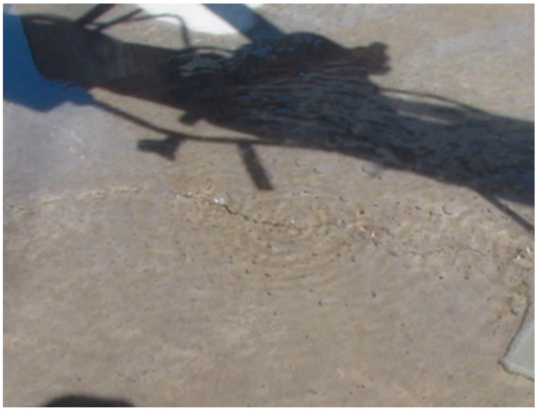
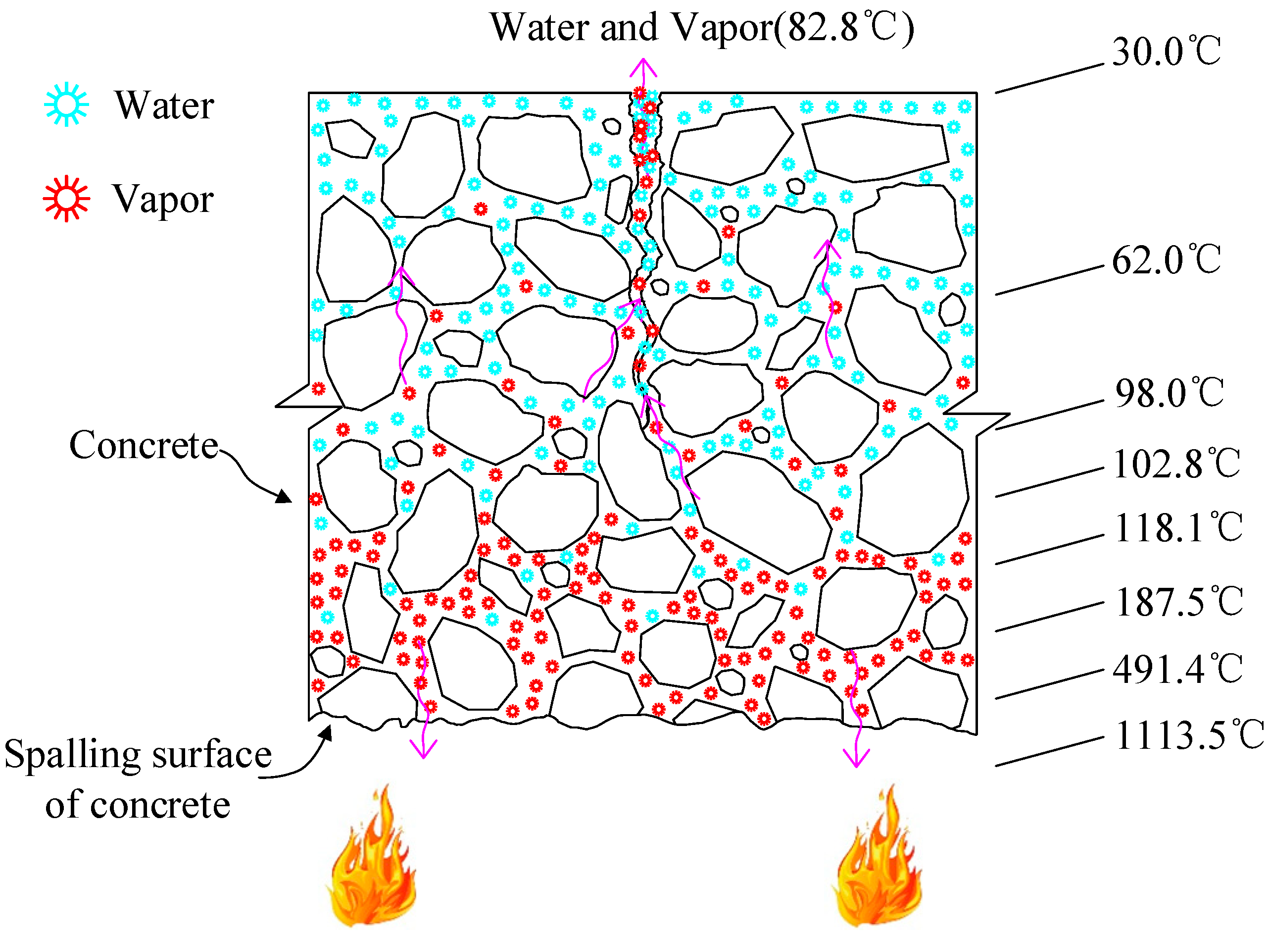
The elevated temperature of fire induces the conversion of moisture in the concrete to water vapor, generating high pressure within the material and driving the migration of moisture. Nonetheless, due to the concrete’s low permeability and compactness, water and vapor predominantly traverse through cracks in the material. Consequently, water and vapor emanating from these fissures exhibit elevated temperatures.
(2)
The migration of high-temperature water and vapor through cracks to a lower-temperature region was driven by vapor pressure in the high-temperature region. By combining the temperature field distribution in the concrete with the temperature of the water and vapor in the cracks, the crack depth can be estimated. At 95 min, cracks on the ceiling’s outer surface extended to the inner surface, with a depth exceeding 150 mm.
(3)
During the heating stage, the fire induces thermal expansion of the concrete inside the tunnel, resulting in tensile cracking of the concrete outside the tunnel. During the cooling stage, decreased temperatures cause the fire-exposed tunnel surface to crack. In the internal and external cracking patterns, immersed tunnels are vulnerable to developing through-cracks during fires. Such through-cracks in the concrete present a direct safety threat to the immersed tunnel. Even when through-cracks are not present, concrete cracking exposes rebars to the marine chloride environment, accelerating their corrosion and diminishing the tunnel’s service life. Therefore, it is crucial to consider the potential for concrete cracking due to thermal strain during the fire-resistant design of immersed tunnels.

Author Contributions

J.D.: Conceptualization, Data Analysis, Investigation, and Writing—Review and Editing; P.Q.: Methodology, Conceptualization, Supervision, and Project Administration; J.L.: Writing—Original Draft, Conceptualization, Supervision, Project Administration, and Funding Acquisition; X.W.: Conceptualization. All authors have read and agreed to the published version of the manuscript.

Funding

This work was supported by the research and development project of the Department of Housing and Urban Rural Development of Guangdong Province (2021-K5-291990, 2021) and (2022-K24-590110, 2022).

Conflicts of Interest

The authors declare that they have no known competing financial interest or personal relationships that could have appeared to influence the work reported in this paper.

References

  1. Pan, D. Study on Mechanical Properties and Damage Laws of Large Diameter Shield Tunnel Lining under Fire Scenario; Beijing Jiaotong University: Beijing, China, 2018. (In Chinese) [Google Scholar]
  2. Dong, Y.L.; Duan, J.T.; Zhang, D.S.; Zhu, S.F.; Qi, J.Q. Experimental research on fire resistance of the reduced scale immersed tunnel with fire in both traffic tubes. Tunn. Undergr. Space Technol. 2023, 132, 104922. [Google Scholar] [CrossRef]
  3. Zhang, J.C.; Shi, J.L.; Qu, Y.T. Technical specifications and operation of Seikan submarine tunnel. China Railw. 2017, 5, 91–97. (In Chinese) [Google Scholar]
  4. Xiao, J.Z.; Liu, L.L.; Dong, Y.L.; Luo, F.J.; Gao, W.Y. Progress of study on explosive spalling of high performance concrete at elevated temperatures. J. Archit. Civ. Eng. 2019, 36, 1–15. (In Chinese) [Google Scholar]
  5. Al-Bashiti, M.K.; Naser, M.Z. Verifying domain knowledge and theories on Fire-induced spalling of concrete through eXplainable artificial intelligence. Constr. Build. Mater. 2022, 348, 128648. [Google Scholar] [CrossRef]
  6. Khoury, G.A. Effect of fire on concrete and concrete structures. Prog. Struct. Mat. Eng. 2000, 2, 429–447. [Google Scholar] [CrossRef]
  7. Wang, W.; Li, D. Thermal-mechanical coupling analysis and fire protection experiment on immersed tunnel exposed to fire. J. Saf. Sci. Technol. 2015, 11, 17–22. (In Chinese) [Google Scholar]
  8. Duan, J.T.; Dong, Y.L.; Zhu, S.F.; Luo, J.Q. Cross-section bearing capacity analysis of immersed tunnel of Hong Kong-Zhuhai-Macao bridge. J. Huaqiao Univ. (Nat. Sci.) 2020, 41, 8–18. (In Chinese) [Google Scholar]
  9. Wang, L.Y.; Xu, W. Internal force analysis of immersed tunnel cross-section during service stage. Struct. Eng. 2015, 31, 162–168. (In Chinese) [Google Scholar]
  10. Xu, P.; Xing, R.J.; Jiang, S.P.; Li, L.J. Theoretical prediction model and full-scale experimental study of central smoke extraction with a uniform smoke rate in a tunnel fire. Tunn. Undergr. Space Technol. 2019, 86, 63–74. [Google Scholar] [CrossRef]
  11. Guo, J.; Jiang, S.P.; Zhang, Z.Y. Fire thermal stress and its damage to subsea immersed tunnel. Procedia Eng. 2016, 166, 296–306. [Google Scholar] [CrossRef]
  12. Duan, J.T.; Dong, Y.L.; Xiao, J.Z.; Zhang, D.S.; Zheng, W.; Zhang, S.Y. A large-scale fire test of an immersed tunnel under the protection of fire resistive coating. Tunn. Undergr. Space Technol. 2021, 111, 103844. [Google Scholar] [CrossRef]
  13. Lu, L.M.; Qiu, J.N.; Yuan, Y.; Tao, J.; Yu, H.T.; Wang, H.; Mang, H. Large-scale test as the basis of investigating the fire-resistance of underground RC substructures. Eng. Struct. 2019, 178, 12–23. [Google Scholar] [CrossRef]
  14. Ring, T.; Zeiml, M.; Lackner, R. Underground concrete frame structures subjected to fire loading: Part I–Large-scale fire tests. Eng. Struct. 2014, 58, 175–187. [Google Scholar] [CrossRef]
  15. China Communications Construction Co. Ltd. Immersed Tunnel Design and Construction Manual—Design; Science Press: Beijing, China, 2019. (In Chinese) [Google Scholar]
  16. Hu, Z.N.; Xie, Y.L.; Xu, G.P.; Bin, S.L.; Liu, H.Z.; Lai, J.X. Advantages and potential challenges of applying semi-rigid elements in an immersed tunnel: A case study of the Hong Kong-Zhuhai-Macao bridge. Tunn. Undergr. Space Technol. 2018, 79, 143–149. [Google Scholar] [CrossRef]
  17. Duan, J.T.; Dong, Y.L.; Lin, J.Q.; Zhu, S.F. Simulation and analysis of fire test furnace based on improved heat balance method. J. Huaqiao Univ. (Nat. Sci.) 2019, 40, 483–488. (In Chinese) [Google Scholar]
  18. Lin, Z.Z.; Tang, C.S.; Zeng, H.; Cheng, Q.; Tian, B.G.; Shi, B. Soil evaporation based on infrared thermal imaging technology. Chin. J. Geotech. Eng. 2021, 43, 743–750. (In Chinese) [Google Scholar]
  19. Stelzner, L.; Powierza, B.; Oesch, T.; Dlugosch, R.; Weise, F. Thermally-induced moisture transport in high-performance concrete studied by X-ray-ct and H~1h-nmr. Constr. Build. Mater. 2019, 224, 600–609. [Google Scholar] [CrossRef]
  20. Li, M. The Fire Damage of High Strength Concrete and Its Comprehensive Evaluation; Southeast University: Nanjing, China, 2005. (In Chinese) [Google Scholar]
Figure 1. Prototype and scale test model of the immersed tunnel. (a) Prototype. (b) Reduced-scale model.
Buildings 13 01412 g001
Figure 2. Section and rebar forms of the immersed tunnel (mm).
Buildings 13 01412 g002
Figure 3. Side view of the fire test.
Buildings 13 01412 g003
Figure 4. Sky view of the fire test.
Buildings 13 01412 g004
Figure 5. Water overflow from concrete cracks on ceiling during fire test.
Buildings 13 01412 g005
Figure 6. Temperature curve of double tube fire test furnace of the immersed tunnel.
Buildings 13 01412 g006
Figure 7. Temperature distribution inside the ceiling. (a) Ceiling of left tube. (b) Ceiling of right tube.
Buildings 13 01412 g007
Figure 8. Variations of concrete temperature along depth inside the ceiling. (a) Ceiling of left tube. (b) Ceiling of right tube.
Buildings 13 01412 g008
Figure 9. Temperature difference between the inner surface and the outer surface of the ceiling.
Buildings 13 01412 g009
Figure 10. Mechanism of concrete cracking caused by uncoordinated thermal strain.
Buildings 13 01412 g010
Figure 11. Cracks on the outer surface of the immersed tunnel. (a) Cracks on the outer surface of the ceiling. (b) Cracks on the outer surface of the arch wall.
Buildings 13 01412 g011
Figure 12. Infrared images of the ceiling during the fire test. (a) At 100 min, the infrared image of ceiling. (b) At 120 min, the infrared image of ceiling. (c) At 140 min, the infrared image of ceiling. (d) At 245 min, the infrared image of ceiling.
Buildings 13 01412 g012
Figure 13. Distribution of main cracks on the outer surface of the immersed tunnel during the fire test.
Buildings 13 01412 g013
Figure 14. Comparison of ceiling concrete temperature and concrete crack temperature during the fire test.
Buildings 13 01412 g014
Figure 15. Boiling water and vapor in the concrete cracks.
Buildings 13 01412 g015
Figure 16. Schematic diagram of temperature field distribution and moisture migration in concrete during fire.
Buildings 13 01412 g016
Table 1. Mix design (C50).
Granite gravel (big) (kg/m3)726
Granite gravel (small) (kg/m3)311
Mix sand (kg/m3)636
Portland cement (kg/m3)390
Water (kg/m3)165
Slag powder (kg/m3)75
Fly ash (kg/m3)35
Water reducer (L/m3)11.5
Disclaimer/Publisher’s Note: The statements, opinions and data contained in all publications are solely those of the individual author(s) and contributor(s) and not of MDPI and/or the editor(s). MDPI and/or the editor(s) disclaim responsibility for any injury to people or property resulting from any ideas, methods, instructions or products referred to in the content.

